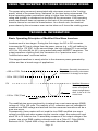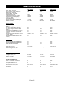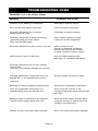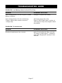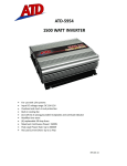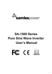
1
AC POWER SOURCE
DC-AC
MODELS:
INVERTERS
PSE-24100A
PSE-24150A
PSE-24250A
OWNER'S MANUAL
Please read this manual before operating your charger.
INDEX
INDEX
Warning ................................................................................. 2
Getting Started ...................................................................... 3
Layout .................................................................................... 4
Features, Controls & Indications .......................................... 5
Selecting the Optimum Power Source .................................. 8
Using proper Wire Cable Sizes .............................................. 8
Installation & Operation ....................................................... 9
Appliances that may not operate correctly
on modified sinewave .......................................................... 11
Powering Television & Audio Equipment .......................... 11
Powering Microwave Ovens ................................................ 12
Technical Information ........................................................ 12
Installation Locations.......................................................... 13
Review ................................................................................. 14
Specifications ...................................................................... 15
Troubleshooting Guide .................................................. 16-17
Notes ................................................................................... 18
Page 1
WARNING
PLEASE TAKE THE FOLLOWING PRECAUTIONS.
FAILURE TO ABIDE BY THESE REQUIREMENTS
WILL VOID THE WARRANTY.
Never parallel the 115V AC output of the inverter with the
output from a generator or electric mains. This will instantly
burn the inverter.
Although this inverter has an input OVER VOLTAGE SHUT
DOWN at 30V, input voltages higher than 30V will cause
permanent damage. Ensure the following when the battery is
being charged simultaneously (the output voltage of the
charging device will be fed to the inverter):
Ensure that the charging voltage of the alternator has not been set above
30V.
Do not use an unregulated solar panel. It's voltage can reach up to 36V on
a very cold day. When using a regulated solar panel, it's voltage should not
be set beyond 30V.
Ensure that the voltage of the battery charger does not exceed 30V in any
condition.
DO NOT REVERSE THE POLARITY OF THE INPUT CONNECTIONS.
THIS WILL PERMANENTLY DAMAGE THE INVERTER.
Page 2
GETTING STARTED
Power equipment and appliances which operate with motors or tubes require an initial surge of power
to get them up and running. This power surge is referred to as the "starting load" or "surge/peak load."
(By comparison devices such as standard light bulbs do not require a starting load). Once the
equipment or appliance has been powered up, it settles down to a slower pace and requires far less
electrical power to operate. This lower power requirement is referred to as the "continuous load."
In order to ensure that the capacity of your power inverter is sufficient to meet the required start up
load, you must first determine the power consumption of the equipment or appliance you plan to
operate.
Power consumption is rated either in wattage or in amperage and information regarding the required
"watts" or "amps" generally is stamped or printed on most appliances and equipment. If this information
is not indicated on the appliance or equipment, check the owner’s manual or contact the manufacturer.
If the power consumption is rated in amps, multiply the number of amps by 117 (AC voltage) to
determine the comparable wattage rating. As a general rule, you can determine the required start up
load by multiplying the wattage rating by 10. It is the start up load of the equipment or appliance you
plan to operate that will determine whether or not your inverter has the required capacity to power it.
For further information on the fundamental operating principles of inverters and related data, see
"Technical Information Section" on page 12.
Don’t Over Load Your Inverter!
Although your power inverter has the capacity to provide power output (excess current) equal to
approximately two times its rated wattage capacity for a very brief period, it is designed to operate
equipment and appliances with start up load wattage ratings no higher than its own maximum continuous wattage rating.
For example, the PSE-24150A model has a maximum continuous rating of 1500 watts. Although this
model has the capacity to briefly provide up to 3000 watts of surge power (that is, excess current), it is
designed to operate equipment and appliances with start up load requirements of 1500 watts or less.
Consequently, if the start up load rating of your equipment or appliance is the same or approximately
the same as the maximum continuous rating of the inverter, the inverter may not have the capacity to
provide the required start up load.
To determine whether your inverter will operate a particular piece of equipment or appliance, run a test.
The inverter is designed to automatically shut down in the event of a power overload and testing
equipment and appliances with start up load ratings comparable to the maximum wattage rating of the
inverter will not damage it.
Some refrigerators, freezers, pumps and other similar equipment and appliances require very high start
up loads to operate. Before attempting to power up this type of equipment or appliance, make
especially certain that all connections have been properly made and that the power source is fully
charged.
Once those conditions have been checked, turn the inverter switch ON and monitor the Battery Voltage
Indicator (See Operating Guidelines & Safety Features). If the Voltage Indicator confirms that the input
voltage is in the acceptable range, turn the inverter switch OFF, ON, OFF and ON again in quick
succession. If this procedure is unsuccessful, it is likely that the inverter does not have the required
start up capacity to operate the equipment or appliance in question.
If the Voltage indicator reading falls below 22 volts during the start up process, a battery with greater
CCA (Cold Cranking Amps) may be required.
Page 3
LAYOUT
PSE-24100A, PSE-24150A
b.
a.
c.
d.
e.
f.
h.
i.
Rear View
Bottom View
g.
PSE-24250A
b.
e.
a.
k.
c.
d.
j.
f.
Front View
h.
g.
i.
Rear View
Page 4
FEATURES, CONTROLS & INDICATIONS
OPERATING & SAFETY FEATURES
Important : Each of the following operating procedures and safety
features must be carefully reviewed and thoroughly understood
prior to using the inverter. Failure to do so may result in damage to
the inverter or equipment or serious personal injury
a. ON/OFF Switch. This switch controls the flow of power from the
power source to the inverter. It does not control the power running
from the inverter to the equipment or appliance being operated.
b. High Temperature LED Indicator Light. This light will turn RED
and the inverter will automatically shut down when the internal
temperature exceeds design parameters for safe operation. When
this occurs, turn the equipment or appliance off.
In the event of excess temperature, the High Speed Cooling Fan also
will automatically turn on. Overheating may result when the inverter is
being operated at levels exceeding its wattage rating or because it
has been placed in a location or in a manner which prevents proper
heat dissipation. After approximately 15 minutes, the High Temperature Indicator light and the Cooling Fan will turn off and the inverter
will automatically restart indicating that the inverter temperature has
dropped to a safe operating level.
c. Over Load LED Indicator Light. This light will turn RED and the
inverter will automatically shut down when the continuous power draw
from the inverter exceeds the maximum continuous power rating for
the inverter. Turn the inverter OFF (0), determine and resolve the
cause of the overload prior to resuming operation of the equipment or
appliance. Turning the inverter ON (I) will re-set it.
Page 5
Battery Current & Voltage Bar Graph Meters (GREEN, YELLOW, RED).
d. Current Indicator. This illuminated Bar Graph monitors the current
being drawn from the battery by the inverter. Depending on the amount of
current being drawn, the Bar Graph reading generally will be in the GREEN
or YELLOW zone. When the reading rises to the RED zone, the inverter
may automatically shut down. In this event it is likely that the draw of the
equipment or appliance being operated is greater than the battery is
capable of producing.
Voltage Indicator. This Bar Graph indicates the DC voltage available at
the input terminals of the inverter. This voltage will be lower than the voltage
at the battery terminals by an amount equal to the voltage drop along the
input cables and connectors. This drop is equal to the product of the input
current and the resistance of the cables and the connectors. When the
output power is low, the input current will be low and the drop will also be
low. The input voltage at the inverter will thus be almost equal to the battery
voltage. At higher output loads, the input current will be higher and the drop
will also be higher, in this case, the input voltage at the inverter will be lower
than the battery voltage.
The inverter is designed to operate with input voltages ranging from 20 to 30
volts of direct current (DC). When the voltage drops below 21 volts DC, the
voltage indicator will register in the lower RED zone and an audible alarm
will sound. If the voltage drops below 21 volts DC, the voltage indicator will
go out and the inverter will automatically shut down.
The inverter will also shut down automatically when the input voltage
exceeds 30 volts DC.
Despite this “built in” protection the inverter may be damaged if the input
voltage exceeds 30 volts DC and damage caused by excess voltage input is
not covered under the warranty. Under optimum conditions, the voltage
reading will be in the GREEN zone.
Note:
In the event of automatic shut down or continuous audible alarm, turn the
inverter OFF (O) until the source of the related problem has been determined and resolved.
e. Two Standard North American NEMA 5-15R Receptacles are
provided on models PSE-24100A and PSE-24150A. On PSE-24250A, the
output is available from unconnected, Live (BLACK), Neutral (WHITE) and
Earth ground (GREEN) wires for connection to an external breaker panel. A
plate with standard North American NEMA 5-15 receptacles(e) wired in
series with a 15 A circuit breaker (j) is provided as an accessory. Use this
receptacle if you require power to be drawn from the front panel. (This will
require connection). As this receptacle(e) is fed through a 15A breaker (j),
the power drawn from here should be limited to 1500 watts.
Page 6
f.) Remote Operation Socket. The inverter is designed to be operated
from a remote location via the remote control switch which plugs into this
socket. This optional accessory is available from Samlex.
g.) High Speed Cooling Fan. This fan will turn on automatically when
the internal temperature exceeds design parameters for safe operation.
The Cooling Fan will automatically turn off when the temperature drops to
a safe operating level. This fan does not run continuously.
h.) Power Input Terminals (WHITE/Negative, RED/Positive)
i.) Chassis Ground Terminal Lug
j.) Circuit Breaker. This is provided for PSE-24250A
k.) Punched Holes. These holes are provided for entry of cables going to
the external Breaker Panel (when hard wired)
Page 7
SELECTING THE OPTIMUM POWER SOURCE
Use a Deep Cycle Battery for powering an inverter as this type of battery is designed
to deliver large currents for long durations. Do not use an automotive starter battery
because these batteries are designed with thinner plates to provide large current for a
very short duration to crank the engine. They are not designed to provide large
currents for long durations.
The capacity of a battery is expressed in Ampere Hours (AH) or in Reserve Capacity
(RC) in minutes. Multiply the Reserve Capacity in minutes by 0.3 to get Ampere Hour
capacity ( e.g. RC of 166 minutes = 166 x 0.3 AH or approx. 50 AH )
The approximate current drawn in Amperes by an inverter from a 24 V battery is
determined by dividing the output power drawn from the inverter by 20. For example if
the full 2500 Watts of output power is drawn from PSE-24250A inverter, the battery will
be required to deliver 125 Amperes ( 2500 Watts divided by 20 = 125 Amperes )
Example for determining battery capacity is given below:
Let us say that it is required to run a 2500-Watt load from PSE-24250A inverter for 2
hours.
Current required to be delivered by the battery = 2500 Watts divided by 20 = 125
Amps
AH required to be delivered by the battery = 125 Amps x 2 Hours = 250 AH
Hence, the AH capacity of the battery should be more than 250 AH ( or 250 divided
by 0.3 = 833 RC )
Use 4 Type 8D 12 V batteries in series-parallel connection to get 400 AH capacity
Note:
The AH capacity can be increased by connecting 2 or more batteries in parallel. For
example, if 4 type 8D , 12 V batteries ( Each 8 D is 12V, 200 AH ) are connected in
series-parallel connections, the net capacity will be 200 AH x 2 = 400 AH at 24V.
When using high capacity inverter in an automobile, do not use the starter battery but
an auxiliary deep cycle battery as explained above. Also, if the starter battery is used
and it gets discharged while powering a load connected to the inverter, it may not be
able to start the automobile engine.
USING PROPER WIRE CABLE SIZES
For safe and proper operation of the inverter, connect the inverter ot the power source
with the thickest wire available and in the shortest length practical.
PSE-24100A (1000 Watt) and PSE-24150A (1500 Watt) Models.
When the inverter and the battery are set up within four feet of each other, use a
minimum of #4 gauge wire to make the connections. Within four to six feet, use a
minimum of #2 gauge wire. At distances of more than six feet, use #0 gauge wire.
Page 8
Regardless of the wire gauge selected to make the connections to the battery, we
recommend use of an “0 Ring Adapter.” Use of #0 gauge wire to make the connections to the inverter may require a “0 to 4 Gauge Adapter”. Both adapters are
available through electronic supply stores including Radio Shack.
PSE-24250A ( 2500 Watt ) Model.
When the inverter and the battery are set up within four feet of each other, use a
minimum of #2 gauge wire to make the connections. Within four to six feet, use a
minimum of #0 gauge wire. At distances of more than six feet, use two #0 gauge
wires connected in parallel to the battery. This connection will require eight 0 Ring
Adapters as referenced above. Alternatively, use #00 (2/0) gauge wire with the
appropriate adapters. These #00 gauge wire adapters are available through most
electronic supply stores.
INSTALLATION & OPERATION
1. Make certain the inverter power switch is in the OFF position.
2. Connect one wire each to the Negative and Positive terminals at the rear of the
inverter and tighten the screws to make a secure connection. Do not over tighten
these screws. (To make these connections on the PSE-24250A model, remove
the supplied nut at each terminal on the inverter, install the wire connectors flush
with the metal backing plates and refasten the nuts securely. DO NOT over tighten
these nuts).
3. Connect the wire from the Negative (-) terminal (WHITE on the PSE-24100A and
PSE-24150A models, BLACK on the PSE-24250A model) on the inverter to the
Negative (-) terminal on the 24 volt power source. Make certain the connection is
secure.
4. Confirm that the wire you have just installed is properly connected. (Specifically,
make certain that the wire is connected to the Negative (-) terminals on both the
inverter and the 24 volt power source).
5. Connect the wire from the Positive (+) terminal (RED on all three models) on the
inverter to the Positive (+) terminal on the power source. Make certain that the
connection is secure.
Note:
DAMAGE CAUSED BY REVERSING POLARITY IS NOT COVERED UNDER WARRANTY
Failure to make a proper connection between the inverter and the power source will
result in reverse polarity. Reverse polarity will blow the internal fuses in the inverter
and permanently damage the inverter. Damage caused by reverse polarity is not
covered under the warranty.
Loose connections can result in a severe decrease in voltage which may cause
damage to the wires and insulation.
The audible alarm may make a momentary “chirp” when the inverter is being connected to or disconnected from the power source. This is normal. Making the
connection between the Positive terminals may cause a spark as a result of current
flowing to charge capacitors within the inverter. This is a normal occurrence. Due to
the possibility of sparking, however, it is extremely important that both the inverter
and the 24 volt battery be well removed from any possible source of flammable
fumes or gases.
CAUTION ! Failure to heed this warning could result in fire or explosion.
Page 9
6. Run a ground from the Ground Lug Terminal at the rear of the inverter to a proper
grounding point using the shortest practical length of 8 AWG wire. Selection of the
grounding point will depend on where you are using the inverter. The ground wire
may be connected to the chassis of your vehicle or to the grounding system in your
boat or to the earth if you are operating the inverter in a remote location. Before
connecting the ground, make certain that the inverter is turned off. Operating the
inverter without properly grounding it may result in electrical shock.
7. Turn the inverter ON (I). Check the Bar Graph Meter on the front panel. The Voltage
Bar Graph should read between 22 and 28 volts depending on the voltage of the
power source. If the reading is not within this range, check the voltage of the power
source and the terminal connections on the power source and the inverter to make
sure they are secure.
Neither the High Temperature or Over Load LED Indicators should be lighted.
8. Turn the inverter OFF (O). The High Temperature and Over Load Indicators may
“blink” briefly. This is normal. Also, the internal audible alarm may make a momentary “chirp.” This is normal.
9. Confirm that the equipment or appliance to be operated is turned off. Plug the
equipment or appliance into one of the two AC receptacles on the front panel of the
inverter.
10.Turn the inverter on. Turn the equipment or appliance on.
Note :
The use of an extension cord from the inverter to the appliance or equipment being
operated will not significantly decrease the power being generated by the inverter. For
best operating results, the extension cord should be no more than 50 feet long.
The following precautions apply to the PSE-24250A ( 2500 Watt ) model only.
a). The AC receptacle on the PSE-24250A is equipped with a 15 amp circuit
breaker. Consequently, this outlet is rated for a maximum output of 1500
watts (117 volts x 15 amps).
To generate the maximum output of 2500 watts, the PSE24250 model should
be connected to a power supply source which has the capacity to produce
125 amps.
If more than one piece of equipment or appliance is to be operated at the
same time, first turn on the inverter and then turn on each piece of equipment or appliance separately to enable the inverter to produce the required
start up loads.
b). The 2500 Watt model is designed for direct wiring to an External Breaker
Panel via the direct wire connection “cut out” (k) on the front panel of the
inverter.
This direct wire connection must be performed only by a licensed electrician.
Failure to make this connectoin properly may result in severe injury.
Page 10
APPLIANCES THAT MAY NOT OPERATE
CORRECTLY ON MODIFIED SINEWAVE
The output waveform of this inverter is a modified sinewave (see page 12)
NOTE: A sine wave rises and falls smoothly (at a slope) and also crosses 0V instantly at
a slope. A modified sinewave rises and falls abruptly (no slope) and also sits at the 0V
level for sometime before crossing over abruptly (no slope). Thus, any appliance that
uses a control circuitry that is required to sense a slope and/or instant zero crossing will
not operate correctly with a modified sinewave. Examples of such appliances are given
below:
• Some models of appliances that have built-in clocks, such as clock radios,
alarm clocks, coffee makers, breadmakers, VCR and microwave ovens may
not keep time correctly.
• Most devices with variable speed such as electric drills may work irrationally
when operating with modified sinewave. The variable speed control may not
work, and the unit may work only at full speed.
CAUTION:
CERTAIN BATTERY CHARGERS FOR CORDLESS BATTERY OPERATED TOOLS,
FLASHLIGHTS, VIDEO CAMERAS AND LAPTOP COMPUTERS MAY GET EXCESSIVELY HOT AFTER 10 TO 15 MINUTE OF USE. THESE CHARGERS SHOULD NOT
BE POWERED FROM THIS WAVEFORM.
POWERING TELEVISION AND AUDIO EQUIPMENT
Although the inverter is shielded and filtered to minimize signal interference, some
interference with your television picture may be unavoidable, especially with weak
signals. However, here are some suggestions that may improve the reception.
1. First, make certain that the television antenna produces a clear signal under normal
operating conditions (i.e., at home plugged into a standard 117 AC wall outlet). Also,
ensure that the antenna cable is properly shielded and of good quality.
2. Change the relative positions of the inverter, antenna cables and television power
cord.
3. Isolate the television, its power cord and antenna cables from the 24 volt power
source by running an extension cord from the inverter to the television set.
4. Coil the television power cord and the input cables running from the 24 volt power
source to the inverter.
5. Attach a "Ferrite Data Line Filter" to the television power cord. More than one filter
may be required. These filters are available at most electronic supply stores including Radio Shack.
Note :
Inexpensive sound systems may emit a "buzzing" sound when operated with the
inverter. This is due to inadequate filters in the sound system. There is no solution to
this problem short of purchasing a sound system with a higher quality power supply.
Page 11
USING THE INVERTER TO POWER MICROWAVE OVENS
The power rating commonly associated with microwave ovens is the "cooking
power" which is the power being "delivered" to the item being microwaved. The
actual operating power requirement rating is higher than the cooking power
rating and typically is referenced on the back of the microwave. If the operating
power requirement does not appear on the back of the microwave, check the
owner's manual or contact the manufacturer. As a thumb rule, the electrical
power drawn by the microwave oven can be taken as 2 times the cooking power.
TECHNICAL INFORMATION
Basic Operating Principles of Modified Sine Wave Inverters.
Inverters work in two stages. During the first stage, the DC to DC converter
increases the DC input voltage from the power source (e.g. a 24 volt battery) to
approx. 155 to 170 VDC. In the second stage, the high voltage DC is converted
to 110 to 120 volts (60 Hz AC), using advanced power MOSFET transistors. The
output waveform resulting from this conversion is a "quasi-sine wave" or a
"modified sine wave" as shown below.
This stepped waveform is nearly similar to the sinewave power generated by
utilities and has a broad range of applications.
Sinewave: Smoothly increases to
its peak and smoothly decreases.
It crosses 0 V sharply at a slope.
+155 to 170V, Peak
110 to 120V, RMS
0V
Modified Sinewave:
Shoots straight up,
levels off at peak &
drops straight down.
Also, it sits at 0 V for
some time.
-155 to 170V, Peak
Time
The modified sine wave produced by inverters has a root mean square (RMS)
voltage of 110 to 120 volts. The majority of AC voltmeters are not calibrated to
measure true RMS voltage and assume that the measured waveform will be a
pure sine wave.
Consequently, these meters will not read the true RMS modified sine wave
voltage correctly and when measuring the inverter output, the meters will read
about 20 to 15 volts too low. To accurately measure of the output voltage of the
inverter, use a true RMS reading voltmeter such as a Fluke 87, Fluke 8060A,
Beckman 4410, Triplett 4200 or any multi-meter identified as true RMS.
Page 12
INSTALLATION LOCATIONS
INSTALLATION LOCATIONS
The inverter will work best when placed on a reasonably flat surface. The
floor of your car or truck is an acceptable location as long as the area is
dry and well ventilated.
To maintain the inverter in proper working condition, note the following
important safety precautions:
! CAUTION !
MOISTURE. Keep the inverter dry. Do not expose it to moisture. Do
not operate the inverter if the devices being operated, or any other
surfaces that may come in contact with any power source, are wet.
Water and many other liquids can conduct electricity which may lead to
serious injury or death.
HEAT. The ambient air temperature should be between 50o and 80o F.
Avoid placing the inverter on or near heating vents, radiators or other
sources of heat. Do not place the inverter in direct sunlight.
VENTILATION. In order to properly disperse heat generated while the
inverter is in operation, keep it well ventilated. While in use maintain
several inches of clearance around the top and sides of the inverter.
FUMES & GASES. Avoid using the inverter near flammable materials.
Do not place the inverter in areas such as battery compartments where
fumes or gases may accumulate.
Page 13
REVIEW
Never parallel the AC output of the inverter with another inverter or other AC
power source
Never attempt to operate the inverter from any power source other than a 24
volt battery.
Always ensure the power cable terminal connections run Negative (-) to
Negative (-) and Positive (+) to Positive (+). Check these connections
frequently to ensure they are secure.
Use the heaviest gauge wire available to connect the inverter to the power
source.
While connecting the inverter to the power source, make certain that the
inverter is well removed from any potential source of flammable fumes or
gases.
Direct connection of the PSE-24250A (2500 Watt) model inverter to an
external breaker panel is to be made only by a licensed electrical technician.
Always ground the inverter before operating it.
Make certain the power consumption of the appliance or equipment you wish
to operate is compatible with the capacity of the inverter.
If the rated power consumption of the equipment is in the range of the rated
capacity of the inverter, test the inverter to ensure that it will operate properly.
When attempting to recharge battery chargers, monitor the temperature of
the battery charger for approximately 10 minutes. If the battery charger
becomes abnormally warm, disconnect it from the inverter immediately.
When operating the inverter with an automobile or marine battery, start the
engine every 15 to 60 minutes and let it run for approximately 10 minutes to
recharge the battery.
In the event a continuous audible alarm or automatic shut off, turn the inverter
OFF immediately. Do not restart the inverter until the source of the problem
has been identified and corrected.
Always disconnect the inverter when not in use.
Do not expose the inverter to moisture.
Avoid placing the inverter near sources of heat or in direct sunlight.
When in use, make certain the inverter is properly ventilated.
Always operate the inverter in accordance with the instructions in this manual.
Failure to do so may result in property damage, personal injury or loss of life.
Page 14
SPECIFICATIONS
PSE-24100A
20-30V
63A
PSE-24150A
20-30V
100A
PSE-24250A
20-30V
150A
117 +/- 5% / -10%
60Hz
1000W
2000W
117 +/- 5% / -10%
60Hz
1500W
3000W
117 +/- 5% / -10%
60Hz
2500W
4000W
Modified Sine Wave
<0.27A
85 to 90%
Modified Sine Wave
<0.35A
85 to 90%
Modified Sine Wave
<0.5A
85 to 90%
30V
30V
30V
21V
20V
21V
20V
21V
20V
Yes
Yes
Yes
Yes
Yes
Yes
1500W +/- 10%
2000W +/- 10%
3500W +/- 10%
Yes
Yes
Yes
INPUT VOLTAGE LED BAR GRAPH
INPUT CURRENT LED BAR GRAPH
RED LED FOR OVERLOAD
RED LED FOR OVERTEMP
Yes
Yes
Yes
Yes
Yes
Yes
Yes
Yes
Yes
Yes
Yes
Yes
Input side DC Fuses
Automotive Type ATC, 32V
15A x 5 pcs.
15A x 8 pcs.
15A x 12 pcs.
0 to 40C
-10 to 65C
Up to 85%
0 to 40C
-10 to 65C
Up to 85%
0 to 40C
-10 to 65C
Up to 85%
Wires for connection to external
distribution panel
Receptacle, NEMA 5-15R
No
No
Yes
2
2
1
Dimensions W x D x H, mm
Weight, Kg.
238 x 342 x 86
4.1
238 x 462 x 86
5.7
216 x 495 x 160
10.1
Input Voltage, Volts DC
Input current at rated continuous
output power, Amperes
Output voltage, Volts RMS
Output frequency, Hz
Continuous output power, Watts
Instantaneous overload (surge)
for 2 sec., Watts
Output Waveform
No load current draws, milli-ampere
Optimum efficiency
PROTECTIONS:
High input voltage shut down & latch,
Volts DC
Low input voltage alarm, volts DC
Low input voltage shutdown & latch,
Volts DC
Temperature controlled fan for cooling
Overtemp. shut-down and automatic
recovery
Continuous overload shut-down & auto
recovery, Watts
Output short circuit shut down & auto
recovery
INDICATIONS:
ENVIRONMENT CONDITIONS:
Operating Temp, deg. C
Storage Temp, deg. C
Relative Humidity
OUTPUT CONNECTORS:
Page 15
TROUBLESHOOTING GUIDE
PROBLEM: Low or No Output Voltage
REASON
POSSIBLE SOLUTION
Capacity of the battery is inadequate.
Use higher capacity battery.
Poor contact with battery terminals.
Clean terminals thoroughly.
Automatic Shutdown due to battery
voltage below 20 volts.
Recharge or replace battery.
Automatic Shutdown as equipment being
operated draws too much power.
Red overload LED lights.
Use a higher capacity inverter
or do not use this equipment.
Automatic Shutdown as the inverter is too hot.
Allow inverter to cool.
Check for adequate ventilation.
Reduce the load on the inverter
to rated continuous power output.
Using incorrect type of voltmeter.
Use true RMS reading meter
See Page 12 “Technical Information" .
Automatic Shutdown due to input voltage
beyond 30V
(this may permanently damage the inverter).
Charging alternator's voltage has been set
beyond 30V, or its regulator has become
defective.
Set the voltage correctly or repair.
Batteries are being charged simultaneously
from an unregulated solar panel or a
regulated solar panel set beyond 30V
Disconnect unregulated solar panel
when using the inverter or set
voltage of regulated solar panel to less
than 30V.
Battery charger connected to the batteries
with its boost voltage higher than 30V.
Disconnect the battery charger when
using the inverter or ensure its boost
voltage is less than 30V.
Polarity of input connection was reversed.
None. Will cause permanent damage.
Page 16
TROUBLESHOOTING GUIDE
PROBLEM: Low Battery Alarm is On All The Time
REASON
POSSIBLE SOLUTION
Input voltage below 21V due to poor or weak
battery condition.
Charge or replace the battery.
Input voltage below 21V due to thin/long
battery cables which cause excessive
voltage drop.
Use lower gauge wire. See
Page 8 "Wire Cable Sizes" section of
this manual. Keep wire length as short
as possible.
PROBLEM: TV Interference
REASON
POSSIBLE SOLUTION
Electrical interference from inverter.
Add a Ferrite data line filter onto the
TV power or See Page 11 "Television
and Audio Equipment" section of this
manual.
Page 17
Thank you purchasing a Samlex AC POWER SOURCE DC - AC inverter.
Please retain your original bill of sale and write down your inverter serial
number on this page. In the event you have a problem with your inverter you
will need to provide your sales receipt and inverter serial number for warranty
service.
NOTES :
________________________________________________
________________________________________________
________________________________________________
________________________________________________
________________________________________________
________________________________________________
________________________________________________
________________________________________________
________________________________________________
________________________________________________
ATTACH YOUR BILL OF SALE HERE :
Page 18
110-17 Fawcett Road, Coquitlam
B.C., Canada V3K 6V2
e-mail: [email protected]
website: www.samlexamerica.com
Version #C (101002)