1
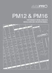
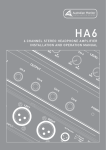
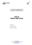
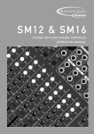
AMIS26
2 INPUT, 6 OUTPUT DISTRIBUTION AMPLIFIER
INSTALLATION AND OPERATION MANUAL
HEADING
1.
IMPORTANT SAFETY INFORMATION
Save the carton and packing material even if the equipment has
arrived in good condition. Should you ever need to ship the unit,
use only the original factory packing.
2. Read all documentation before operating your equipment.
Retain all documentation for future reference.
3. Follow all instructions printed on unit chassis for proper operation.
4. Do not spill water or other liquids into or on the unit, or operate the
unit while standing in liquid.
5. Make sure power outlets conform to the power requirements listed
on the back of the unit.
6. Do not use the unit if the electrical power cord is frayed or broken.
The power supply cords should be routed so that they are not likely
to be walked on or pinched by items placed upon or against them,
paying particular attention to cords and plugs, convenience
receptacles, and the point where they exit from the appliance.
7. Always operate the unit with the AC ground wire connected to the
electrical system ground. Precautions should be taken so that the
means of grounding of a piece of equipment is not defeated.
8. Mains voltage must be correct and the same as that printed on the
rear of the unit. Damage caused by connection to improper AC
voltage is not covered by any warranty.
9. Have gain controls on amplifiers turned down during power-up to
prevent speaker damage if there are high signal levels at the
inputs.
10. Power down & disconnect units from mains voltage before making
connections.
11. Never hold a power switch in the “ON” position if it won’t stay
there itself!
12. Do not use the unit near stoves, heat registers, radiators, or other
heat producing devices
13. Do not block fan intake or exhaust ports. Do not operate
equipment on a surface or in an environment which may impede
the normal flow of air around the unit, such as a bed, rug,
weathersheet, carpet, or completely enclosed rack. If the unit
is used in an extremely dusty or smoky environment, the unit
should be periodically “blown free” of foreign matter.
14. Do not remove the cover. Removing the cover will expose you to
potentially dangerous voltages. There are no user serviceable
parts inside.
15. Do not drive the inputs with a signal level greater than that
required to drive equipment to full output.
16. Do not connect the inputs / outputs of amplifiers or consoles to
any other voltage source, such as a battery, mains source, or
power supply, regardless of whether the amplifier or console is
turned on or off.
17. Do not run the output of any amplifier channel back into another
channel’s input. Do not parallel- or series-connect an amplifier
output with any other amplifier output.
Australian Monitor Inc is not responsible for damage to
loudspeakers for any reason.
18. Do not ground any red (“hot”) terminal. Never connect a “hot”
(red) output to ground or to another “hot” (red) output!
19. Non-use periods. The power cord of equipment should be unplugged
from the outlet when left unused for a long period of time.
20. Service Information Equipment should be serviced by qualified
service personnel when:
A.
B.
C.
D.
E.
The power supply cord or the plug has been damaged.
Objects have fallen, or liquid has been spilled into the
equipment
The equipment has been exposed to rain
The equipment does not appear to operate normally,
or exhibits a marked change in performance
The equipment has been dropped, or the enclosure damaged.
THIS SAFETY INFORMATION IS OF A GENERAL NATURE AND MAY BE SUPERSEDED BY INSTRUCTIONS CONTAINED WITHIN THIS MANUAL
INTRODUCTION AND CONTENTS
The Australian Monitor Installation Series AMIS26 is a high quality
2 input, 6 output distribution amplifier.
The AMIS26’s 2 inputs can be balanced or unbalanced and each input’s
sensitivity can be switched between Mic and Line level. 15VDC
Phantom power is individually switchable per input and for ease of
setup, a four segment LED level meter is provided per input.
Each of the AMIS26’s inputs is individually assignable to any of the
6 outputs via front panel DIP switches. Outputs can be balanced or
unbalanced and feature up to 30dB of attenuation, so they can be run
as any combination of line level or mic level outputs. Ample label space
is provided for both inputs and outputs and the AMIS26 is powered via
a supplied 20VAC power supply.
INTRODUCTION
3
FRONT PANEL
4
REAR PANEL
5
INTERNAL ADJUSTMENT
6
BLOCK DIAGRAM
7
DIMENSIONS
8
SPECIFICATIONS
9
The AMIS26 provides a low noise, feature packed, signal routing
solution to cover a wide range of installation needs at a contractor
friendly price.
AUS, EUR, USA
Copyright 3rd Dec 2003
Rev A: 3rd Dec 2003
Rev B: 11th Aug 2004
Rev C: 22nd Feb 2005
Rev D: 1st June 2005
This symbol is intended to alert the user to the presence
of uninsulated “dangerous voltage” within the product’s
enclosure that may be of sufficient magnitude to
constitute a risk of electric shock to persons.
This symbol is intended to alert the user to the presence
of important operation and maintenance (servicing)
instructions in the literature accompanying the appliance.
Caution:
AMIS26 INSTALLATION & OPERATION MANUAL
To prevent electric shock do not use this (polarised) plug
with an extension cord, receptacle or other outlet unless
the blades can be fully inserted to prevent blade exposure.
To prevent electric shock, match wide blade of plug to
wide slot, fully insert.
PAGE 3
FRONT PANEL
1
2
3
4
1 INPUT LEVEL CONTROL(S)
The input level controls are screwdriver
adjustable trim pots. The input level controls
can boost or cut the input
signal by up to 15dB.
2 LEVEL METER
These 4 segment LED meters show the
strength of each of the AMIS26's input
signals. LED segments are calibrated to the
following level markings and show
the following colours:
-20dBu (green)
-10dBu (green)
0dBu (yellow)
+10dBu (red)
4 POWER LED
This blue LED indicates the unit is powered
“on”.
3a
3b
3 OUTPUT SECTION
3a INPUT ASSIGN SWITCHES
These recessed DIP switches assign input
A and input B to a desired output.
3b OUTPUT LEVEL CONTROLS
The output level controls are screwdriver
adjustable trim pots. These level controls
attenuate the output level, with a range
from -60dB at 'Minimum” position to 0dB
at “Maximum” position.
PAGE 4
AMIS26 INSTALLATION & OPERATION MANUAL
REAR PANEL
4
3
2
1
1 INPUT A/B CONNECTORS
The balanced XLR inputs can be used
as Mic or Line level inputs and are
switched between input sensitivities via
internal DIP switches accessed through
the lid (see internal adjustments section
page 6). The dual RCA inputs are
Line level inputs only and are internally
summed to mono.
2 OUTPUT CONNECTORS
The AMIS26's outputs can be either
balanced XLR or unbalanced dual RCA’s.
Both these outputs can be switched
between Mic level & Line level via internal
DIP switches accessed through the lid
(see internal adjustments section page 6).
3 20VAC POWER CONNECTOR
This 2.1mm connector accepts power
from the provided 20VAC power supply.
4 EARTH STUD
In some circumstances it may be
necessary to ground the unit to eliminate
noise in the system. This can be done
by using this earth stud.
NOTE: This stud provides a
connection to chassis ground.
Audio ground is internally tied
to chassis ground.
AMIS26 INSTALLATION & OPERATION MANUAL
PAGE 5
INTERNAL ADJUSTMENT
NOTE: The following adjustments involve access to the inside
of the AMIS26 and should only be attempted by a qualified technician.
All internal adjustments are accessible through the lid of the AMIS26.
Always turn off the AC power and remove the AC power cord before
accessing the inside of the AMIS26.
1
3
2
1 INPUT SENSITIVITY DIP
SWITCHES. DIP1 (INPUT A),
DIP3 (INPUT B) SWITCHES 1, 2
Switches 1 and 2 on this 3 pole DIP
switch when selected to the “on” position
will switch the balanced XLR input to
Mic level. The “off” position will switch
the balanced XLR input to Line level.
The Default setting is Line level.
☛
NOTE: This switch does not
effect the sensitivity of the
unbalanced dual RCA input.
2 PHANTOM POWER SWITCH.
DIP1 (INPUT A), DIP3 (INPUT B)
SWITCH 3
This switch will enable 15VDC phantom
power to the desired input. The default
setting is “off”.
☛
PAGE 6
NOTE: Before switching Phantom
power on please ensure that no
line level source equipment is
connected to the effected input.
3 OUTPUT LEVEL DIP SWITCH.
DIP 2 Switch 1 (OUTPUT 1)
DIP 2 Switch 2 (OUTPUT 2)
DIP 4 Switch 1 (OUTPUT 3)
DIP 4 Switch 2 (OUTPUT 4)
DIP 5 Switch 1 (OUTPUT 5)
DIP 5 Switch 2 (OUTPUT 6)
This switch will change the output
sensitivity of the desired output from Mic
to Line level. When the switch is “on” the
output level will be switched to Mic level.
☛
NOTE: This switch effects
both balanced XLR & dual
RCA outputs.
AMIS26 INSTALLATION & OPERATION MANUAL
BLOCK DIAGRAM
AMIS26 INSTALLATION & OPERATION MANUAL
PAGE 7
DIMENSIONS
PAGE 8
AMIS26 INSTALLATION & OPERATION MANUAL
SPECIFICATIONS
DIMENSIONS (h x w x d)
44.0 x 482.0 x 168.0 mm
1.73”x19.0”x6.61”
Line In (XLR/RCA) 0.02%
Mic In (XLR) 0.1%
THD
SHIPPING DIMENSIONS (h x w x d)
10Hz - 50kHz
FREQUENCY RESPONSE (0DB/-3DB)
500 x 90.0 x 270.0 mm
3.55”x19.7”x10.6”
-89dB
NOISE
WEIGHT
POWER INPUT
Net 2.5kg Shipping 3.0kg
Net 5.5lb Shipping 6.6lb
20VAC
12VA max
CROSSTALK
Better than 80dB
PHANTOM POWER
MAX IN/OUT(HEADROOM)
SENSITIVITY (FOR 0dBu OUT)
LINE (XLR)
MIC (XLR)
LINE (RCA)
OUTPUT MIC/LINE GAIN SWITCH
775mV (0dB)
10mV (-37dB)
775mV (0dB)
15VDC
15dB
All measurements referenced to 0dBu (0.775mV)
All measurements done with levels set In/Out at 0dB
30dB
AMIS26 INSTALLATION & OPERATION MANUAL
PAGE 9
AUSTRALIA AND NEW ZEALAND
www.australianmonitor.com.au
SYDNEY
MELBOURNE
BRISBANE
ADELAIDE
PERTH
AUCKLAND
(NSW & ACT SALES)
(VIC & TAS SALES)
(QLD SALES)
(SA & NT SALES)
(WA SALES)
(NZ SALES)
149 Beaconsfield
Street Silverwater
NSW 2128
Private Bag 149
Silverwater NSW 1811
Phone: (02) 9647 1411
Fax: (02) 9648 3698
Email:
[email protected]
22/277
Middleborough Road
Box Hill VIC 3128
PO Box 151 Blackburn
South VIC 3130
Phone: (03) 9890 7477
Fax: (03) 9890 7977
Email:
[email protected]
42 Commercial Road
Fortitude Valley
QLD 4006
PO Box 871 Fortitude
Valley QLD 4006
Phone: (07) 3852 1312
Fax: (07) 3252 1237
Email:
[email protected]
31 Walsh Street
Thebarton
SA 5031
PO Box 157
Hindmarsh SA 5007
Phone: (08) 8352 4444
Fax: (08) 8352 4488
Email:
[email protected]
299 Fitzgerald Street
West Perth WA 6005
PO Box 404
North Perth
WA 6906
Phone: (08) 9228 4222
Fax: (08) 9228 4233
Email:
[email protected]
Unit B, 11 Piermark
Drive Albany 1331
New Zealand
PO Box 512
Albany 1331
Phone: (09) 415 9426
Fax: (09) 415 9864
Email:
[email protected]
EUROPE/ASIA/MIDDLE EAST
USA/SOUTH AMERICA
www.australianmonitor.com.au
www.australianmonitor.com
INTERNATIONAL SALES
SENNHEISER ELECTRONIC CORPORATION
149 Beaconsfield Street Silverwater NSW 2128 Australia
Private Bag 149 Silverwater NSW 1811
Phone: 61 2 9647 1411
Fax: 61 2 9648 3698
Email: [email protected]
1 Enterprise Drive
Old Lyme CT 06371 USA
Phone: 1 860 434 9190
Fax: 1 860 434 1759
Email: [email protected]