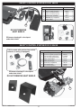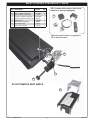
1
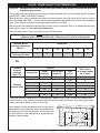
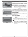
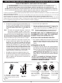
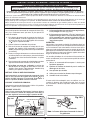
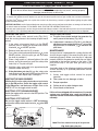
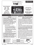
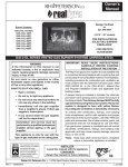
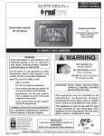
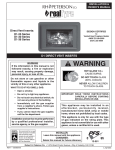
OWNER’S
MANUAL
DESIGN CERTIFIED
to
Vented Decorative Appliance
ANSI Z21.60-2012
CSA 2.26-2012
Standard Burner Systems:
PB-**(P)A
PB-**-01(M)(P)
PB-**-11(M)(P)
PB-**-15(M)(P)
PB-**-17(M)(P)
FOR INSTALLATION IN
SOLID-FUEL BURNING
FIREPLACES*
**Sizes:
(18, 24, 30)
FOR USE WITH
FYRE GLASS / FYRE GEMS
PB SERIES VENTED GAS BURNER SYSTEMS (REGULATED)
IMPORTANT: READ THESE INSTRUCTIONS
CAREFULLY BEFORE STARTING
INSTALLATION OF THE SYSTEM
The Real-Fyre gas burner system is to be installed only
in a solid-fuel burning fireplace with a working flue and
constructed of noncombustible material.The installation,
including provisions for combustion and ventilation air
must conform with the National Fuel Gas Code, ANSI
Z223.1/NFPA 54, or the CSA B149.1, Natural Gas
and Propane Installation Code, and applicable local
building codes.
A damper clamp is included to maintain the minimum
permanent vent opening and to prevent full closure of
the damper blade. The chimney damper MUST be fully
opened when burning the burner system.The burner
system is designed to burn with yellow flames;
thus adequate ventilation is absolutely necessary.
To comply with certification, listings, and building
code acceptances, and for safe operation and proper
performance of this burner system, use ONLY Peterson
parts and accessories. Use of other controls, parts, and
accessories that are not designed for use with RealFyre gas burner systems is prohibited and will void all
warranties, certifications, listings, and building code
approvals, and may cause property damage, personal
injury, or loss of life.
*Note: Solid-fuels shall not be burned in a fireplace
where a decorative appliance is installed.
WARNING
If the information in this manual is not
followed exactly, a fire or explosion
may result, causing property damage,
personal injury, or loss of life.
Do not store or use gasoline or other
flammable vapors and liquids in the
vicinity of this or any other appliance.
WHAT TO DO IF YOU SMELL GAS:
• Open a window.
• Do not try to light any appliance.
• Do not touch any electrical switch; do
not use any phone in the building.
• Immediately call the gas supplier
from a neighbor’s phone. Follow gas
supplier’s instructions.
• If you cannot reach the gas supplier,
call the fire department.
Installation and service must
be performed by a qualified
professional installer, service
agency, or the gas supplier.
This appliance is only for use with the
type of gas indicated on the rating plate.
INSTALLER:
Leave this manual with the appliance.
CONSUMER:
Retain this manual for future reference.
254-L-18b-5
ROBERT H. PETERSON CO. • 14724 East Proctor Avenue • City of Industry, CA 91746
REV 7 - 1305231430
1
L-A2-227
manuel des
propriétaires
CONCEPTION CERTIFIÉE
Systèmes standard de brûleur:
PB-**(P)A
PB-**-01(M)(P)
PB-**-11(M)(P)
PB-**-15(M)(P)
PB-**-17(M)(P)
**Sizes:
(18, 24, 30)
à
Vented Decorative Appliance
ANSI Z21.60-2012
CSA 2.26-2012
POUR L’INSTALLATION EN
CHEMINÉES BRÛLANTES DE
COMBUSTIBLE SOLIDE*
POUR L'USAGE AVEC
VERRE/GEMMES
SYSTÈMES EXHALÉS PAR SÉRIE DE BRÛLEUR À GAZ DE PB (RÉGLÉS)
AVERTISSEMENT
Si l’information en ce manuel n’est pas
suivie exactement, une incendie ou une
explosion peut résulter, entraînant des dégats
matériels, des blessures, ou la perte de la vie.
Ne stockez pas ou n’employez pas l’essence
ou d’autres vapeurs et liquides inflammables
à proximité de ceci ou d’aucun autre appareil.
CE QUI À FAIRE SI VOUS SENTEZ LE GAZ:
• Ouvrez une fenêtre.
• N’essayez pas de n’allumer aucun appareil.
• Ne touchez aucun commutateur
électrique; n’utilisez aucun téléphone
dans le bâtiment.
• Appelez immédiatement le fournisseur
de gaz du téléphone du voisin. Suivez les
instructions du fournisseur de gaz.
• Si vous ne pouvez pas atteindre le
fo u r n i s s e u r d e g a z , a p p e l e z l e
département de feu.
L’installation et le service doivent être assurés
par un installateur qualifié et professionnel,
l’agence de service, ou le fournisseur de gaz.
Cet appareil sert seulement avec le type de
gaz indiqué de la plaque de contrôle.
INSTALLATEUR :
Laissez ce manuel avec l'appareil.
CONSOMMATEUR:
Maintenez ce manuel pour la future référence.
IMPORTANT: L I S E Z C E S I N S T RU C T I O N S
SOIGNEUSEMENT AVANT DE
COMMENCER L'INSTALLATION DU
SYSTÈME.
Le Vrai-Fyre système de brûleur à gaz doit être installée
seulement dans une cheminée brûlante de combustible
solide avec une conduite de cheminée fonctionnante
et être construit avec du matériel non-combustible.
L'installation, y compris des dispositions pour l'air de
combustion et de ventilation doit se conformer au code
national de gaz de carburant, la norme ANSI Z223.1/
NFPA 54, ou le CSA B149.1, code d'installation de gaz
naturel et de propane, et codes du bâtiment locaux
applicables.
Une bride plus humide est incluse pour maintenir
l'ouverture permanente minimum de passage et pour
empêcher la pleine fermeture de la lame plus humide.
L'amortisseur de cheminée DOIT être entièrement ouvert
en brûlant le système de brûleur. Le système de brûleur
est conçu pour brûler avec les flammes jaunes ; ainsi
à ventilation proportionnée est absolument nécessaire.
Pour se conformer à la certifi cation, les listes, et
les acceptations de codes du bâtiment, et pour
l'exploitation sûre et l'exécution appropriée de ce
système de brûleur, utilisent SEULEMENT des pièces
et des accessoires de Peterson. L'utilisation d'autres
commandes, pièces, et accessoires qui ne sont pas
conçus pour l'usage avec de Vrais-Fyre systèmes de
brûleur à gaz est interdite et videra toutes les garanties,
certifications, listes, et approbations de codes du
bâtiment, et peut causer des dégats matériels, le
dommage corporel, ou des pertes humaines.
*Note: Des Plein-carburants ne seront pas brûlés
dans une cheminée où un appareil décoratif
est installé.
254-L-18b-5
ROBERT H. PETERSON CO. 14724 East Proctor Ave., City of Industry, CA 91746 , USA
REV 7 - 1305231430
2
L-A2-227
TABLE OF CONTENTS
4
5
5
6
6
7
8
9
11
12
12
13
13
13
13
14
15
15
17
19
21
23
24
24
24
24
24
25
26
28
PARTS LIST
SAFETY CONTROL SYSTEM FOR MANUAL VALVE
SAFETY CONTROL SYSTEM FOR 11 VALVE
SAFETY CONTROL SYSTEM FOR 01 VALVE
SAFETY CONTROL SYSTEM FOR 15 VALVE
SAFETY CONTROL SYSTEM FOR 17 VALVE
IMPORTANT INFORMATION
IMPORTANT PRE-INSTALLATION AND FIREPLACE SAFETY INFORMATION
GLASS / GEMS QUANTITY DETERMINATION
INSTALLATION
INSTALLING THE BURNER
01 VALVE MODELS ONLY
CONNECTING THE IGNITION PACK TO THE VALVE
INSTALLING OR REPLACING BATTERIES FOR IGNITION MODULE PACK
SWITCH BOX PLACEMENT
NOTES PAGE
GLASS / GEMS PLACEMENT
BURNER PREPARATION
LIGHTING INSTRUCTIONS - MANUAL PILOT AND SERIES 17 VALVE
LIGHTING INSTRUCTIONS - SERIES 11 VALVE
LIGHTING INSTRUCTIONS - SERIES 15 VALVE
LIGHTING INSTRUCTIONS - SERIES 01 VALVE
CLEANING AND MAINTENANCE
MAINTENANCE
CLEANING
SERVICE
FLAME DESCRIPTION
PILOT BURNER ADJUSTMENT (IF EQUIPPED)
TROUBLESHOOTING
WARRANTY
REV 7 - 1305231430
3
L-A2-227
PARTS LIST
Before installation, check that your gas burner system is complete. See the PARTS LIST below. If any
parts are missing or damaged, contact your Real-Fyre® dealer before installing or using the burner.
Be sure you know the model and size of your set when ordering options or replacement parts and
accessories.
18" model
Item Description
24" model
30" model
Part No. Qty. Part No. Qty. Part No. Qty.
1.
Burner pan
PB-18F
1
PB-24F
1
PB-30F
1
2.
Heat shield (see inset)
--
--
--
--
--
--
3.
Control valve (see inset)
--
--
--
--
--
--
CK-5-SP
1
CK-5-SP
1
CK-5-SP
1
DC-1
1
DC-1
1
DC-1
1
CS-10
LF-15-7
1
1
CS-15
LF-15-7
1
2
CS-10
LF-15
2
1
4.
Flex connector w/ adapter
5.
Damper clamp
6.
or
Select sand granules (natural gas)
Vermiculite granules (propane gas)
Manual valve
11 series
See your local dealer for
replacement parts.
1
15 series
Note: Photos not to scale.
3
2
17 series
4
01 series
5
6
Glass / gems are purchased and packaged separately.
Quantity will vary, depending on selection. Glass and
gems are available in various colors; contact your
dealer for further details.
REV 7 - 1305231430
4
For all valves, see detailed
information on the following
pages.
L-A2-227
SAFETY CONTROL SYSTEM FOR MANUAL VALVE
6
4
5
Item Description
1.
2.
3.
or
4.
or
5.
6.
Part No.
Control knob
Manual SPK valve
Pressure regulator, natural gas
Pressure regulator, propane gas
Pilot assembly, natural gas
Pilot assembly, propane gas
Heat shield, valve
Heat shield, regulator
KNOB-6
SV-19
PR-3NAT
PR-2LP
PT-1NAT
PT-1LP
HS-32
HS-39
Qty.
3
1
1
1
1
1
1
1
1
2
1
DO NOT REMOVE
HEAT SHIELD
SAFETY CONTROL SYSTEM FOR 11 VALVE
Item Description
1.
or
2.
or
3.
4.
Valve assembly (natural)
Valve assembly (propane)
Pilot assembly (natural)
Pilot assembly (propane)
Remote kit (if equipped)
Heat shield
Part No.
SV-6
SV-6P
PAC-3NAT
PAC-3LP
RR-1A
HS-36
Qty.
3
1
1
1
1
1
1
2
4
DO NOT REMOVE
HEAT SHIELD
1
PB burner showing 11 valve layout
under heat shield
REV 7 - 1305231430
5
L-A2-227
SAFETY CONTROL SYSTEM FOR 01 VALVE
Item Description
1.
or
2.
or
3.
4.
5.
1
2
Part No.
Pilot assembly (natural)
Pilot assembly (propane)
Valve assembly (natural)
Valve assembly (propane)
Qty.
PAC-6
PAC-7
SV-32
SV-33
IMP-1
RR-1A
HS-37
Switch box assembly
Remote kit (if equipped)
Heat shield
1
1
1
1
1
1
1
5
3
DO NOT REMOVE
HEAT SHIELD
PB burner showing 01 valve layout
under heat shield
4
SAFETY CONTROL SYSTEM FOR 15 VALVE
VR-1A remote with receiver, heat shield,
batteries, & wiring (if equipped)
Item Description
1.
or
2.
or
3.
or
4.
5.
6.
4
Part No.
Pressure regulator, natural gas
Pressure regulator, propane gas
Pilot assembly (natural gas)
Pilot assembly (propane gas)
Valve, natural gas
Valve, propane gas
Remote kit (if equipped)
Heat shield, valve
Heat shield, regulator
PR-3NAT
PR-2LP
PT-1NAT
PT-1LP
SV-22
SV-23
VR-1A
HS-38
HS-39
Qty.
1
1
1
1
1
1
1
1
1
2
PB burner showing 15 valve layout
under heat shield
DO NOT REMOVE HEAT SHIELD
6
3
1
5
REV 7 - 1305231430
6
L-A2-227
SAFETY CONTROL SYSTEM FOR 17 VALVE
Item Description
1.
2.
or
3.
or
4.
5.
6.
7.
Part No.
Valve
Pilot assembly, natural gas
Pilot assembly, propane gas
Pressure regulator, natural gas
Pressure regulator, propane gas
Control knob
Remote kit (if equipped)
Heat shield, valve
Heat shield, regulator
VR-1A remote with receiver, heat shield,
batteries, & wiring (if equipped)
Qty.
SV-37
PT-1NAT
PT-1LP
PR-3NAT
PR-2LP
KNOB-9
VR-1A
HS-35
HS-39
1
1
1
1
1
1
1
1
1
5
Optional manual system or upgrade to
VR-2 remote system.
2
3
1
4
DO NOT REMOVE HEAT SHIELD
6
REV 7 - 1305231430
7
L-A2-227
IMPORTANT INFORMATION
Important:
Do not use this burner system if any part has been
underwater. Immediately call a qualified professional
service technician to inspect the appliance and to
replace any part of the control system and any gas
control which has been underwater.
The gas burner system must be isolated from the gas
supply piping system by closing its individual shut-off
valve during any pressure testing of the gas supply
system at test pressures equal to or less than 1/2
psig. The gas burner system and its individual shutoff valve must be disconnected from the gas supply
piping system when testing at pressures in excess
of 1/2 psig.
Keep the area of the gas burner system clear and
free from combustible materials, gasoline, and other
flammable vapors and liquids.
Burner
size
Min. Fireplace
Dimensions
Width*
The minimum inlet gas supply pressure for purpose
of input adjustment is 5" for natural gas and 11" for
propane gas. Maximum inlet gas supply pressure for
this burner is 10.5" for natural and 13" for propane gas.
Gas supply pipe must be 1/2" minimum interior diameter
or larger. If the gas line is longer than 20', a larger
diameter line may be necessary.
A fireplace screen must be in place when the
system is burning. Provisions for adequate
combustion air must be maintained. Unless other
provisions for combustion air are provided, the
screen shall have an opening(s) for introduction of
combustion air. Combustion air is adequate when
all flames curl into the fireplace and away from the
screen. When a glass fireplace enclosure (door) is
used, leave the doors fully open when the system
is in operation.
The minimum firebox dimensions in which the burner
system is certified to be installed, is listed in the
Technical Data Table here.
BTU
Depth Height
18"
28"
16"
18"
75k
60k
24"
34"
16"
18"
90k
75k
30"
40"
16"
18"
110k
90k
For safe operation and proper
performance and to comply
with CSA Certification, ONLY
Robert H. Peterson parts and
accessories must be used with
this gas burner system.
* This required width allows for centering of the system.
Note: For remote ready units, the maximum
BTU thru put of some valves may vary.
Minimum Free Opening Area of Chimney Damper for Venting (sq. in.)
For Factory-Built Fireplaces
For Masonry-Built Fireplaces
Chimney
18"
24"
30"
18"
24"
30"
15' (min.)
36
46
52
46
55
65
20'
29
38
46
43
50
59
25'
26
32
43
-
-
-
30'
23
29
38
39
45
53
Note: The minimum chimney height from hearth to top of chimney is 15'.
IMPORTANT
For all valves, the air MUST be purged from the gas line before the pilot will light and burn properly. The time
needed to purge will depend on the length of the gas line to the unit and the amount of time since the unit or gas
line was last used. It may take several minutes before all the air is purged and the pilot will light and burn properly.
Follow the LIGHTING INSTRUCTIONS section in this manual.
REV 7 - 1305231430
8
L-A2-227
IMPORTANT PRE-INSTALLATION AND FIREPLACE SAFETY INFORMATION
CAUTION: Installation and repair must be done by an NFI Certified or other qualified professional
installer.
Installer:
Carefully read these instructions before installing this gas burner system. Be sure you understand
all safety precautions and warnings contained in this manual.
A. This appliance is designed as an attended appliance. Adults must be present when this gas appliance is operating.
Do not leave this unit burning when unattended or while anyone is sleeping.
B. This appliance is only for use with the type of gas indicated on the rating plate. This appliance is NOT FIELD
CONVERTIBLE for use with other gasses.
C. BE CAREFUL: If not installed, serviced, and used correctly per these instructions, this product can cause
serious personal injury, property damage, or loss of life.
D. WARNING: Before installing in a solid-fuel-burning fireplace, the chimney flue, damper, and firebox must be
thoroughly CLEANED of soot, creosote, ashes, and loose paint, and must be inspected by a qualified chimney
cleaner. Some older fireplaces may need repair prior to installing this appliance.
E. CHECK GAS TYPE (natural or propane): The gas supply must be the same as stated on your burner system rating
plate. If gas supply is different, DO NOT INSTALL. Contact your dealer for immediate assistance.
F.
Keep the area of the gas burner system clear and free from combustible materials, gasoline, and other flammable
vapors and liquids.
G. INSUFFICIENT GAS PRESSURE WILL KEEP THE PILOT (IF EQUIPPED) FROM OPERATING PROPERLY. DO NOT
USE IF GAS PRESSURE IS LOWER THAN THE MINIMUM REQUIREMENT.
H. The minimum inlet gas-supply pressure for purposes of input adjustment is 5" water column (w.c.) on natural gas
and 11" w.c. on propane gas. Insufficient gas pressure will affect proper operation of the pilot (if equipped). Do not
install this gas appliance if minimum pressure is not available. The maximum inlet gas-supply pressure is 10.5" w.c.
on natural gas and 13" w.c. on propane gas. The propane source must be regulated. (Do not connect this appliance
directly to an unregulated propane gas tank - this can cause an explosion.)
I.
The gas piping system must be sized to provide minimum inlet pressure at the maximum flow rate (BTU/hr).
Undue pressure loss will occur if the pipe is too small, or the run is too long. Gas supply pipe must be 1/2" minimum
interior diameter. If the gas line is longer than 20', a larger diameter line may be necessary. Refer to the NFPA 54
guidelines for further details.
J. Input ratings shown in BTU per hour are for elevations up to 2,000 ft. For elevations above 2,000 ft., refer to the National
Fuel Gas Code or contact manufacturer before installing this product.
K. This gas appliance and its main gas valve must be disconnected from the gas-supply piping system during any pressure
testing of that system at test pressures in excess of 1/2 psig.
L. This gas appliance must be isolated from the gas-supply piping system by closing the equipment shutoff valve connected
to the gas-supply line during any pressure testing of the gas-supply piping system at test pressures equal to or less
than 1/2 psig.
M. Do not use this appliance if any part has been underwater. Immediately call a qualified service technician to inspect the
appliance and to replace any part of the control system and any gas control that has been underwater.
N. A fireplace screen must be in place when the system is burning. Provisions for adequate combustion air must be
maintained. Unless other provisions for combustion air are provided, the screen shall have an opening(s) for introduction
of combustion air. Combustion air is adequate when all flames curl into the fireplace and away from the screen. When
a glass fireplace enclosure (door) is used, leave the doors fully open when the system is in operation.
O. This appliance may be installed in an aftermarket, permanently located, manufactured (mobile) home, where not
prohibited by local codes. Installation of appliances designed for manufactured home (U.S. only) or mobile home
installation must conform with the Standard CAN/CSA Z240 MH, Mobile Housing, in Canada, or with the Manufactured
Home Construction and Safety Standard, Title 24 CFR, Part 3280, in the United States, or when such a standard is not
applicable, ANSI/NCSBCS A225.1/NFPA 501A, Manufactured Home Installations Standard.
P. PETERSON (REAL FYRE) GLASS OR GEMS ARE THE ONLY MEDIA CERTIFIED TO BE USED IN THIS BURNER.
DO NOT USE ANY OTHER MEDIA. Correct installation of the glass/gems and proper placement and installation of the
burner assembly, are imperative to safe operation of your appliance. Problems WILL occur if all items are not properly
installed.
9
L'INFORMATION DE SÛRETÉ IMPORTANTE DE PRÉINSTALLATION ET DE CHEMINÉE
ATTENTION:
L'installation et la réparation doivent être faites par un NFI certifié ou tout autre installateur professionnel
qualifié.
Installateur:
Lisez soigneusement ces instructions avant d'installer ce système de brûleur à gaz. Soyez sûr que vous comprenez
tous les mesures de sécurité et avertissements contenus en ce manuel.
A. Cet appareil est conçu comme appareil occupé. Les adultes doivent être présent quand cet appareil à gaz fonctionne. Ne
laissez pas ce burning d'unité si sans surveillance ou tandis que n'importe qui dort.
B. Cet appareil sert seulement avec le type de gaz indiqué de la plaque de contrôle. Cet appareil n'est pas CONVERTIBLE de
CHAMP pour l'usage avec d'autres gaz.
C. FAITES ATTENTION: Sinon installé, entretenu, et utilisé correctement par ces instructions, ce produit peut causer
le dommage corporel, les dégats matériels, ou les pertes humaines sérieux.
D. AVERTISSEMENT: Avant l'installation dans une cheminée plein-carburant-brûlante, la conduite de cheminée, l'amortisseur, et
le foyer de cheminée doivent ÊTRE COMPLÈTEMENT NETTOYÉS de la suie, de la créosote, des cendres, et de la peinture
lâche, et doivent être inspectés par un décapant qualifié de cheminée. Quelques cheminées plus anciennes peuvent ont
besoin de réparation avant d'installer cet appareil.
E. VÉRIFIEZ LE TYPE de GAZ (normal ou propane) : La fourniture de gaz doit être identique qu'indiquée de votre plaque de
contrôle de système de brûleur. Si la fourniture de gaz est différente, N'INSTALLEZ PAS. Contactez votre revendeur pour
l'aide immédiate.
F.
Gardez le domaine du clair réglé de notation de gaz et libérez des matériaux combustibles, l'essence, et d'autres vapeurs
et liquides inflammables.
G. LA PRESSION DE GAZ INSUFFISANTE GARDERA LE PILOTE DU FONCTIONNEMENT CORRECTEMENT (SI ÉQUIPÉ).
N'EMPLOYEZ PAS SI LA PRESSION DE GAZ EST INFÉRIEURE À LA CONDITION MINIMUM.
H. L'admission minimum gaz-fournissent la pression aux fins de l'ajustement d'entrée est 5" ; colonne d'eau (w.c.) sur le gaz
naturel et le 11" ; w.c. sur le gaz de propane. La pression de gaz insuffisante affectera l'opération appropriée du pilote (si
équipé). N'installez pas cet appareil à gaz si la pression minimum n'est pas disponible. L'admission maximum gaz-fournissent
la pression est 10.5" ; w.c. sur le gaz naturel et le 13" ; w.c. sur le gaz de propane. La source de propane doit être réglée. (Ne
reliez pas cet appareil directement à un réservoir de gaz non réglé de propane - ceci peut causer une explosion.)
I.
Le système sifflant de gaz doit être classé pour fournir la pression d'admission minimum au débit maximum (BTU/
hr). La perte de pression anormale se produira si la pipe est trop petite, ou la course est trop longue. La pipe de fourniture de
gaz doit être 1/2" ; diamètre intérieur minimum. Si la ligne de gaz est plus longue que 20' ; une ligne de plus grand diamètre
peut être nécessaire. Reportez-vous aux directives NFPA 54 pour plus de détails.
J.
Les estimations d'entrée montrées en Btu par heure sont pour des altitudes jusqu'à 2.000 pi. Pour des altitudes au-dessus de
2.000 pi, référez-vous au code national de gaz de carburant ou entrez en contact avec le fabricant avant d'installer ce produit.
K. Cet appareil à gaz et son clapet à gaz principal doivent être disconnected du gaz-fournissent le système sifflant pendant tout
vérificateur de pression de ce système aux pressions d'essai au-dessus de 1/2 psig.
L.
Cet appareil à gaz doit être isolé dans gaz-fournissent le système sifflant en fermant le robinet d'isolement d'équipement relié
au gaz-fournissent la ligne pendant tout vérificateur de pression du gaz-fournissent le système sifflant aux pressions d'essai
égales à ou moins d'à 1/2 psig.
M. N'employez pas cet appareil si n'importe quelle partie a été sous-marine. Appelez immédiatement un technicien qualifié de
service pour inspecter l'appareil et pour remplacer n'importe quelle partie du système de contrôle et de n'importe quelle
commande de gaz qui a été sous-marine.
N. Una pantalla de la chimenea debe ser en el lugar cuando el sistema está quemando. Las provisiones para el aire de
combustión adecuado deben ser mantenidas. A menos que otras provisiones para el aire de combustión se proporcionen, la
pantalla tendrá una abertura para la introducción de aire de combustión. El aire de combustión es adecuado cuando todas
las llamas se encrespan en la chimenea y lejos de la pantalla. Cuando se utiliza un recinto de cristal de la chimenea
(puerta), deje las puertas completamente abiertas cuando el sistema es en funcionamiento.
O. Cet appareil peut être installé dans un marché des accessoires, maison (mobile) de manière permanente située et manufacturée,
où non interdit par des codes locaux. L'installation des appareils a conçu pour la maison manufacturée (États-Unis seulement)
ou installation de caravane résidentielle doit se conformer au CAN/CSA standard Z240 MH, logement mobile, au Canada, ou à
la construction et au standard de sécurité à la maison manufacturés, intitulent 24 CFR, la partie 3280, aux Etats-Unis, ou quand
une telle norme ne s'applique pas, à ANSI/NCSBCS A225.1/NFPA 501A, installations à la maison manufacturées standard.
P. LE VERRE OU LES GEMMES DE PETERSON (VRAI FYRE) SONT LES SEULS MÉDIAS CERTIFIÉS POUR ÊTRE
EMPLOYÉ DANS CE BRÛLEUR. N'EMPLOYEZ AUCUN AUTRE MILIEU. L'installation correcte du verre/gemmes et le
placement et l'installation appropriés du brûleur, sont impérative à l'exploitation sûre de votre appareil. Les problèmes se
poseront si tous les articles ne sont pas correctement installés.
10
GLASS / GEMS QUANTITY DETERMINATION
CAUTION: Sand granules are for use with natural gas systems only. Always use vermiculite granules
for propane gas systems.
The granules that come with the burner system are pre-measured and must be used per these instructions
(see GLASS / GEMS PLACEMENT section).
Decorative glass / gems (purchased separately) must be placed to cover the burner (but not on the valve or
pilot, if equipped). See Table 11-1 for the minimum bag requirement depending on your burner size. Additional
glass / gems may be purchased and placed around the burner if desired.
Should you wish to fill the entire fireplace floor with glass / gems; instead use Table 11-2 to determine how many
bags of glass / gems to order based on fireplace size.
One 10-lb. bag of glass / gems fills approximately 144 cubic inches.
CAUTION: When covering the burner with glass / gems; do not exceed 1" above the top of the burner.
Additional glass / gems directly on top of the burner may result in unsafe ignition.
Minimum burner
coverage requirement
Table 11-1
Glass / gem
10 lb. bag(s) needed
Burner size
16
18
24
30
36
42
1
1
1
1
2
2
- OR Fireplace
complete
coverage
Table 11-2
Fireplace
Opening size
28"
36"
Standard
Fireplace Sizes 32" see-thru
42"
50"
Center
width (in.)
Front to back
depth (in.)
Area
(sq. in.)
Glass / gems
10 lb. bags needed
for 2" depth
25
16
400
6
540
8
30
23
690
10
31
23
713
10
36
30
828
12
1085
15
1334
19
46
33
These bag quantities listed allow for an approximate 2" depth of glass / gems in the entire fireplace floor,
without a burner. (The volume of the burner will take up some space, allowing for some excess glass to be
used as desired, or stored as extra for later use.)
Your fireplace area can be determined by measuring the
center width of your fireplace in inches and multiplying by
the depth from front to back in inches. You can then use
the area column in the table above to approximate the
number of bags needed.
Center
Width
DEPTH
Depth
11
H
eight
HEIGHT
INSTALLATION
The damper clamp with hex bolt (Fig. 12-1) is provided as a means to
prevent full closure of the damper blade. The clamp is easily attached to most
damper blades with pliers or a wrench, and must be permanently installed.
The clamp is designed to prevent accidental closure of the damper when
installed as illustrated (Fig. 12-2 and Fig. 12-3). Should the clamp not fit, or
fail to provide the permanent vent opening listed in the table found above,
have a permanent stop installed, remove the damper
blade, or have the damper cut to provide the minimum Set screw
permanent opening required.
Note: T h e s e a r e m i n i m u m d a m p e r o p e n i n g
specifications. The damper must be completely
opened when operating this gas appliance to
achieve the best ventilation possible.
Damper clamp
Fig. 12-1
Open
Closed
Fig. 12-2
Fig. 12-3
INSTALLING THE BURNER
The Real-Fyre gas burner system must be installed by a qualified professional service technician. Instructions
must be followed carefully to ensure proper performance and full benefit from the gas burner system. Check to
be sure the burner system is designed and labeled for the type of gas (natural or propane gas) supplied
to the fireplace. Fireplace floor must be level, clean, and smooth.
WARNING: Failure to position the parts in accordance with these diagrams or failure to use only parts
specifically approved with this appliance may result in property damage or personal injury.
REFER TO THE PARTS LIST WHEN FOLLOWING THESE INSTRUCTIONS.
1. MAKE SURE THE FIREPLACE GAS SUPPLY IS TURNED OFF.
2. Locate the gas-supply stub inside the fireplace and remove the cap, if attached (see Fig. 12-4).
CAUTION: When removing the cap, make sure the stub does not turn, loosening the connection inside the wall.
3. Attach the nut end of the flex connector (Item 4) to the adapter found on the valve or, if attached, on the
regulator behind the valve. Tighten securely.
4. Place the burner system into the fireplace so that it is centered
centered.and the open burner pan faces outward.
5. Be sure gas to the fireplace is off. Attach the large adapter end of the flex connector (Item 4) to the gas-supply
stub using a pipe compound resistant to all gases. Ensure adapter (and nut) are tightened securely. Ensure
the pan rests level on the fireplace floor after connection. Adjust the pan if necessary.
6. LEAK TEST: Turn on the fireplace gas supply, and test at all connections for leaks using the appropriate soapy
water solution. If bubbles appear, a leak is present. Turn off the gas and tighten at all connections. Repeat
until no leaks are present. If a leak persists, turn off the gas supply and contact the local gas company or
dealer. NEVER USE A FLAME TO CHECK FOR LEAKS.
Turn off the gas supply prior to proceeding.
Fig. 12-4
7. Place the heatshield over the regulator and/or valve.
Important:
Heatshields must be in place during operation
of the gas burner system. Overheating of the
valve will cause shut down of the gas burner
system or other operating problems.
8. If this unit was shipped with a remote, read and follow the
separate remote instructions (packed with remote) for
complete remote installation.
12
Gas line
cap
Gas supply
line stub
01 VALVE MODELS ONLY
CONNECTING THE IGNITION PACK TO THE VALVE
The 01valve comes complete with the wiring harness connected to the switch box. You may wish to ensure it is correctly
connected before finally connecting the three wires to the valve, as below.
Check Connections
TO CHECK THE WIRING ASSEMBLY:
"I" wire
B
A. Check that the wiring harness is fitted tightly into the connector on the
green ignitor pack inside the switch box (Fig. 13-1).
A
Wire harness
connector
B. Check that the female connectors on the two black wires from the pilot
assembly (wires marked "I" and "S") are inserted fully into the male
connectors on the ignitor pack (Fig. 13-2).
C. Check the connection of the red and black wires of the wire harness to
the respective counterpart wires from the battery holder (red-red and
black-black). The two brown wires should be connected to the switch.
Note:
Fig. 13-1
"S" wire
Ignitor pack
The two spare brown wires with coated male connectors are used
to connect a remote system (if equipped).
Fig. 13-2
D. Connect the wires to the valve in the following order (see Fig. 13-2):
D
Orange wire marked THTP - to THTP connector on valve
Black wire marked TP - to TP connector on valve
Green wire
marked THTP
Black wire marked TP
Orange wire marked THTP
Green wire marked TH - to TH connector on valve
The diagram below shows the wiring layout for the complete unit.
INSTALLING OR REPLACING BATTERIES FOR IGNITION
MODULE PACK
Two 1.5-volt (D-cell) alkaline batteries are supplied with the burner system.
To install or replace batteries, remove any old batteries (if applicable) and
install new batteries according to the diagram illustrated on the battery holder
mounted inside the switch box (Fig. 13-3).
Note:
ON/OFF switch
Fig. 13-3
Ignitor
pack
Switch
box
For the system to work properly, it is suggested that you replace
the batteries annually with fresh batteries. Always replace all the
batteries at the same time.
Battery
pack
SWITCH BOX PLACEMENT
Place the switch box outside of the firebox and a minimum of 6" from the burner/flame. If the switch box is in the firebox, the
switch box must only be oriented as shown in Fig. 13-4. The switch box must not be placed in the rear of the fireplace, or in
any other manner than shown in Fig. 13-4. Set the box on its side and place the bottom of the box toward the right firebox wall
(box must be a minimum of 6" from the burner/flame). Be sure that the pilot and valve wire bundles remain clear of the burner,
valve, and heat shield at all times.
Note: Coil excess wire within the switch box.
CAUTION: THE SWITCH BOX MAY BE HOT DURING AND AFTER OPERATION.
Fig. 13-4
(FIREBOX)
Pilot wire
bundle
Consult this wiring diagram to ensure correct connection of wires.
Burner pan
Switch box
Valve magnet wire
(black)
(do not remove)
Wire harness
Orange (THTP)
(FIREBOX)
Valve and heat shield
Wire bundles go around the valve
and away from the burner. Coil
excess wire under switch box.
Rear of control panel
6"
min
Remote valve
2x D cells
Valve wire bundle
IF SWITCH BOX IS INSIDE FIREBOX; ORIENT ONLY AS SHOWN
BELOW:
Bottom
BOX ON ITS SIDE
Green (TH)
Remote
receiver
(optional)
Brown 2
wires
wires to
switch
(inside
box)(inside of
switch box)
(FIREBOX)
Black (TP)
(Red) to
battery holder
Switch box
6"
min
(Black) to
Battery
holder
Ignitor pack
I
Switch
13
S
S
To pilot assembly
I
probes
Sensor
Ignitor
Wiring diagram for 01 Valve
Fig. 13-5
NOTES PAGE
Please use this page to record any information about your unit that you may want to have at hand.
14
GLASS / GEMS PLACEMENT
BURNER PREPARATION
(Pack granules in pan)
Burner pan
Granules
up to baffle
Fig. 15-1
Separator
screen
After hooking up the burner to the fireplace gas supply and placing
the heat shield on the valve assembly (if applicable), the decorative
media (granules and glass / gems) must be added for the burner
to function as designed.
Note: Installation is the same for glass and gems. Glass
shown here. These instructions show sand granules
being used as a base for the glass, but only natural-gas
burners use sand. For propane burners, follow these
instructions using vermiculite.
WARNING
The burner and pilot (if equipped) must be OFF (fully extinguished),
and all valve covers must be in place before pouring media onto
the burner. It may also be necessary to temporarily cover the pilot
assembly (if equipped) to keep media out of it during this procedure.
GRANULE PLACEMENT
Pour the granules into the pan, just below level of the center flame
baffle. Then pack the granules into the pan. Add additional granules
as needed (see Fig. 15-1).
Fig. 15-2
Fig. 15-3
GLASS / GEMS PLACEMENT
CAUTION: Glass pieces may have sharp edges. Be careful handling
the glass. Use hand protection, such as gloves, if
necessary.
1. Pour the glass / gems directly on top of the burner pan so that
the burner pan is covered completely and evenly (see Fig. 15-2).
DO NOT exceed a 1" depth of glass directly above the burner
pan.
Note: At this stage the burner will function as designed; however,
more glass / gems may be added around the burner for
decorative purposes.
2.
Add additional glass / gems around the burner pan as
desired (Fig. 15-3).
15
INSTRUCTIONS D’ÉCLAIRAGE - PILOTE ET VALVE MANUELS DE LA SÉRIE 17
POUR VOTRE SÛRETÉ, LISEZ AVANT DE S’ALLUMER
AVERTISSEMENT: Si vous ne suivez pas ces instructions exactement, une incendie ou une
explosion peut résulter entraînant des dégats matériels, des blessures ou la perte de la vie.
N’employez pas cet appareil si n’importe quelle partie a été sous-marine. Réclamez immédiatement un technicien
de service professionnel qualifié et pour inspecter l’appareil et pour remplacer n’importe quelle partie du système de
commande et de n’importe quelle commande de gaz qui a été sous l’eau.
Le Vrai-Fyre système de brûleur a un pilote qui peut être allumé à la main en utilisant une allumette ou un allumeur. En allumant le pilote,
suivez ces instructions exactement.
AVANT DE S’ALLUMER, sentez tous autour du secteur de brûleur pour le gaz. Soyez sûr de sentir à côté du plancher car un certain gaz
est plus lourd que l’air et arrangerez sur le plancher. SI VOUS SENTEZ LE GAZ, SUIVEZ LES INSTRUCTIONS À LA P. 1.
Utilisez seulement votre main pour enfoncer ou pour tourner le bouton de commande de gaz. N’utilisez jamais les outils. Si le bouton
n’enfoncera pas ou ne tournera pas à la main, n’essayez pas de le réparer. Appelez un technicien de service professionnel qualifié et. La
force ou la réparation essayée peut avoir comme conséquence l’incendie ou l’explosion.
ALLUMER LE PILOTE
ALLUMAGE DU BRÛLEUR PRINCIPAL
1. Si le bouton de soupape de commande de brûleur n’est
pas dans la position de OFF, enfoncez la poignée de
commande de gaz légèrement et tournez-vous dans
le sens des aiguilles d’une montre
vers OFF (fig.
16-1).
1. Assurez-vous que le pilote brûle.
2. Tournez la poignée de commande de gaz dans le sens
contraire des aiguilles d’une montre
à ON (fig. 161) pour mettre à feu le brûleur. Le brûleur mettra à feu.
Note: Examinez périodiquement la flamme pilote pour
Le bouton de commande de brûleur ne peut pas
assurer le modèle approprié de flamme (Fig. 16-1).
être tourné du PILOT au OFF à moins que la
poignée soit enfoncée légèrement. Ne forcez pas. ASSUREZ-VOUS QUE LE THERMOCOUPLE ET
Attendez cinq minutes pour dégager dehors n’importe quel L’ASSEMBLÉE PILOTE SONT EN ALIGNEMENT
gaz. Si vous sentez alors le gaz, ARRÊTEZ ! Informez votre CORRECT AVEC L’UN L’AUTRE (FIG. 16-1).
fournisseur de gaz ou le département de feu immédiatement.
ROTATION OUTRE DU BRÛLEUR PRINCIPAL
Si vous ne sentez pas le gaz, passez dessus à l’étape 2.
Note:
Si le pilote ne s’allumera pas, répétez les étapes 1. et 2.
•
Si le pilote ne restera pas s’allumait après que plusieurs
essais, tournent la poignée de commande de gaz à
OFF et appellent votre fournisseur de technicien ou
de gaz de service.
S’ÉTEINDRE LE PILOTE
1. Si complet l’arrêt est désiré, de la position PILOT,
de l’enfoncer le bouton de commande légèrement
et du tour dans le sens des aiguilles d’une montre
à la position de repos. Ne forcez pas le bouton.
NE FORCEZ PAS LE BOUTON. Ceci exigera du
pilote d’être re-s’est allumé avant d’utiliser le brûleur
encore.
Le SPK-17 est capable de l’éclairage à distance.
Si votre unité est équipée d’un extérieur, lisez
et suivez les instructions à distance séparées
d’actionner le brûleur à distance.
OFF
(valve manuelle montrée)
Thermocouple
OFF
ON
1. S’ALLUMER - tournez le bouton
de commande de brûleur à OFF
et attendez 5 minutes avant de
s’allumer.
Fig. 16-1
PILOT
ON
PILOT
Pilot
PILOT
ON
ON
PILOT
•
1. De la position de ON, tournez le bouton de commande
dans le sens des aiguilles d’une montre
à la position
PILOT. Le brûleur s’éteindra et le pilote restera s’est
allumé.
OFF
le sens contraire des aiguilles d’une montre
au
PILOT (fig. 16-1). Poussez la poignée de commande
toute la manière dedans et tenez-la. Tenez une longue
allumette de cheminée ou un proche plus léger le
thermocouple pour allumer le pilote. Continuez à tenir
le bouton de commande pour approximativement 30
secondes après que le pilote est allumé pour permettre
au thermocouple de détecter la flamme pilote, puis
libérez le bouton. Le pilote restera s’est allumé.
OFF
2. Tournez le bouton de commande de brûleur dans
1. Tournez le cadran dans 2. Tournez le cadran dans 3.
le sens des aiguilles
le sens contraire des
à
d’une montre
aiguilles d’une montre
OFF seulement quand
à la position PILOT.
l’arrêt complet est
Avec le bouton prêt de
nécessaire.
pression d’allumette
dedans et la prise
pendant 60 secondes
tout en allumant le pilote.
16
Tournez le bouton
contre- dans le
sens des aiguilles
d’une montre à ON
au brûleur léger.
LIGHTING INSTRUCTIONS - MANUAL PILOT AND SERIES 17 VALVE
FOR YOUR SAFETY, READ BEFORE LIGHTING
WARNING
If you do not follow these instructions exactly, a fire or explosion may result, causing property
damage, personal injury, or loss of life.
Do not use this appliance if any part has been underwater. Immediately call for a qualified professional service technician to
inspect the appliance and to replace any part of the control system and any gas control that has been underwater.
The Real-Fyre® burner system has a pilot that can be lit by hand using a match or lighter. When lighting the pilot, follow these
instructions exactly.
BEFORE LIGHTING, smell all around the burner area for gas. Be sure to smell next to the floor, as some gas is heavier than
air and will settle on the floor. IF YOU SMELL GAS, FOLLOW THE INSTRUCTIONS ON P. 1.
Use only your hand to push in or turn the gas control knob. Never use tools. If the knob will not push in or turn by hand, don't try
to repair it. Call a qualified professional service technician. Excessive force or attempted repair may result in fire or explosion.
LIGHTING THE PILOT
IGNITING THE MAIN BURNER
1. Push in the gas control knob slightly and turn
to OFF (Fig. 17-1). Refer to
clockwise
the PARTS LIST for the location of the burner
control valve knob.
1. Make sure the pilot is burning.
2. Turn the gas control knob counterclockwise
to ON (Fig. 17-1) to ignite the burner. The burner
will ignite.
Note: The burner control knob cannot be turned
from PILOT to OFF unless the knob is
pushed in slightly. Do not force.
Note: Periodically check the pilot flame for the
proper flame pattern (Fig. 17-1).
MAKE SURE THE THERMOCOUPLE AND PILOT
ASSEMBLY ARE IN CORRECT ALIGNMENT WITH
EACH OTHER (Fig. 17-1).
Wait five minutes to clear out any gas. If you then
smell gas, STOP! Notify your gas supplier or the
fire department immediately. If you don’t smell gas,
go on to step 2.
TURNING OFF THE MAIN BURNER
2. Turn the burner control knob counter-clockwise
to PILOT (Fig. 17-1). Push the control
knob firmly and fully in and hold. Hold a long
fireplace match or lighter near the thermocouple
to light the pilot. Continue to hold the control
knob in for approximately 30 seconds after the
pilot is lit, then release the knob. The pilot will
remain lit.
If the pilot will not stay lit after several tries,
turn the gas control knob to OFF and call your
service technician or gas supplier.
The series 17 valve is capable of remote operation. If this
unit was shipped with a remote, or if a remote system
was installed later, read and follow the separate remote
instructions to operate the burner remotely.
OFF
(Manual valve shown)
Thermocouple
OFF
ON
1. Lighting -Turn the burner control knob
to OFF
and wait 5 minutes before
lighting.
PILOT
ON
PILOT
Pilot
PILOT
ON
ON
PILOT
•
1. If complete shutdown is desired, from the PILOT
position, push in the control knob slightly and
to the OFF position. Do not
turn clockwise
force the knob. This will require the pilot to be
relit before using the burner again.
OFF
If the pilot will not light, repeat steps 1 and 2.
EXTINGUISHING THE PILOT
OFF
•
1. From the ON position, turn the control knob
clockwise
to the PILOT position. The burner
will extinguish, and the pilot will remain lit.
3. Tur n the knob
1. Tu r n t h e k n o b 2. Turn knob
counterclockwise
counterclockwise
clockwise to OFF
to ON to light the
to PILOT position. With
only when
burner.
match ready, press
complete shutdown
knob in and hold for 60
is desired or prior to
seconds while lighting
lighting the pilot.
pilot.
Pilot Assembly
Fig. 17-1
17
INSTRUCTIONS D’ÉCLAIRAGE - VALVE DE LA SÉRIE 11
POUR VOTRE SÛRETÉ, LISEZ AVANT DE S’ALLUMER
AVERTISSEMENT : Si vous ne suivez pas ces instructions exactement, une incendie ou une
explosion peut résulter entraînant des dégats matériels, des blessures ou la perte de la vie.
N’employez pas cet appareil si n’importe quelle partie a été sous-marine. Réclamez immédiatement un technicien
de service professionnel qualifié et pour inspecter l’appareil et pour remplacer n’importe quelle partie du système de
commande et de n’importe quelle commande de gaz qui a été sous l’eau.
Le Vrai-Fyre système de brûleur a un pilote qui peut être allumé à la main en utilisant une allumette ou un allumeur. En allumant le pilote,
suivez ces instructions exactement.
AVANT DE S’ALLUMER, sentez tous autour du secteur de brûleur pour le gaz. Soyez sûr de sentir à côté du plancher car un certain gaz
est plus lourd que l’air et arrangerez sur le plancher. SI VOUS SENTEZ LE GAZ, SUIVEZ LES INSTRUCTIONS À LA P. 1.
Utilisez seulement votre main pour enfoncer ou pour tourner le bouton de commande de gaz. N’utilisez jamais les outils. Si le bouton
n’enfoncera pas ou ne tournera pas à la main, n’essayez pas de le réparer. Appelez un technicien de service professionnel qualifié et. La
force ou la réparation essayée peut avoir comme conséquence l’incendie ou l’explosion.
ALLUMANT LE PILOTE
AJUSTANT LE PILOTE
1. La flamme pilote devrait encercler le bout de générateur,
et est préréglée à l’usine (Fig. 18-2).
Pour lire le bouton de commande de soupape de sûreté (Fig.
18-1) lisez l’indicateur formé par larme la plus proche en
métal d’inscription.
2. Si l’ajustement est nécessaire, (Fig. 18-1) tournez la vis
d’approche de gaz dans le sens contraire des aiguilles
pour augmenter la flamme pilote, ou
d’une montre
pour diminuer dans le sens des aiguilles d’une montre
la flamme pilote.
1. Si le bouton de commande de soupape de sûreté est
en position PILOT, enfoncez légèrement sur le bouton
et tournez-le dans le sens des aiguilles d’une montre
jusqu à la position de OFF.
ENTRETIEN
Votre brûleur à casserole est équipé d’un pilote de sûreté qui
coupera l’offre de gaz au cas où le pilote serait ne brûlant pas
ou ne fonctionnant pas correctement. Assurez-vous que le
pilote est ajusté correctement et que les agrafes de cosse de
générateur sont étroitement reliées aux vis terminales sur la
valve. Si le pilote ne restera pas allumait, appelle votre utilité
de gaz ou fournisseur locale de gaz.
2. Libérez le bouton et attendez cinq minutes.
3. Tournez le bouton de soupape de sûreté dans le sens
à la position
contraire des aiguilles d’une montre
PILOT (seulement le gaz pilote coulera quand le bouton
est enfoncé).
4. Placez une longue allumette ou un allumeur de butane
au brûleur pilote et en même temps, poussent le bouton
de soupape de sûreté entièrement dedans. Le pilote
s’allumera.
Un contrôle périodique du suivant devrait être exécuté au
moins annuellement par un représentant qualifié de service
professionnel.
5. Tenez le bouton de soupape de sûreté dedans pendant
approximativement 60 secondes avant de libérer.
1. Valves et commande d’interrupteur à levier pour
l’opération appropriée.
6. Si le pilote ne reste pas s’allumait, la position de
OFF de bouton de soupape de sûreté dans le sens des
entièrement. Attendez cinq
aiguilles d’une montre
minutes, puis répétez les étapes 3. à 5.
2. Système de conduite de cheminée pour la rouille, les
dommages ou les fuites.
3. Une opération plus humide.
METTANT À FEU LE BRÛLEUR PRINCIPAL
4. Orifices pour la saleté ou d’autres corps étrangers.
Avec lampe témoin, tournent le bouton de soupape de sûreté
dans le sens contraire des aiguilles d’une montre
à la
position de ON. Commutez la commande d’interrupteur à
levier à la position de ON et le brûleur s’allumera.
5. Contrôle visuel sur le brûleur.
Si cette unité était embarquée avec un extérieur, ou si un
système à distance était installé plus tard, lisez et suivez
les instructions à distance séparées d’actionner le brûleur
à distance.
COUPANT LE BRÛLEUR PRINCIPAL
Commutez la commande d’interrupteur à levier à la position
de OFF. Le pilote restera s’est allumé.
COUPANT LE PILOTE
Soyez sûr que commande d’interrupteur à levier est éteint et
enfonce et tourne le bouton de soupape de sûreté dans le
sens des aiguilles d’une montre
à la position de OFF.
INTERRUPTEUR
INTERRUPTEURÀÀLEVIERINTERRUPTEUR
LEVIERINTERRUPTEURÀÀLEVIER
LEVIER
Fig.
Fig. 18-1
18-1
Fig. 18-2
Generator
HARNAIS DE
HARNAIS
PORT
PILOTE
DEDE
GAZ
CÂBLAGEDE
PORT
PILOTE
GAZ
CÂBLAGE
VIS PILOTE
VIS PILOTE
DE CAP
À L’EXTÉRIEUR
(si c’est approprié)
Pilot
IN
Electrode
OUT
IN
TH TH
TP
TP
BOUTON
BOUTON DE
DE
COMMANDE
COMMANDE
Note: La flamme pilote devrait encercler le dessus
du générateur
DE
DE VALVE
VALVE DE
DE
SAFTEY
SAFTEY
18
LIGHTING INSTRUCTIONS - SERIES 11 VALVE
FOR YOUR SAFETY, READ BEFORE LIGHTING
WARNING
If you do not follow these instructions exactly, a fire or explosion may result, causing property
damage, personal injury, or loss of life.
Do not use this appliance if any part has been underwater. Immediately call for a qualified professional service technician
to inspect the appliance and to replace any part of the control system and any gas control that has been underwater.
The Real-Fyre® burner system has a pilot that can be lit by hand using a match or lighter. When lighting the pilot, follow
these instructions exactly.
BEFORE LIGHTING, smell all around the burner area for gas. Be sure to smell next to the floor, as some gas is heavier than
air and will settle on the floor. IF YOU SMELL GAS, FOLLOW THE INSTRUCTIONS ON P. 1.
Use only your hand to push in or turn the gas control knob. Never use tools. If the knob will not push in or turn by hand, don't
try to repair it. Call a qualified professional service technician. Force or attempted repair may result in fire or explosion.
LIGHTING THE PILOT
ADJUSTING THE PILOT
To read the safety valve control knob (Fig. 19-1),
read the marking nearest the teardrop-shaped metal
pointer.
1. If the safety valve control knob is in the PILOT
position, push in slightly on the knob and rotate it
clockwise
to the OFF position.
2. Release knob and wait five (5) minutes.
3. Turn safety valve knob counterclockwise
to the
PILOT position. (Only the pilot gas will flow when
the knob is pushed in.)
4. Place a long match or a butane lighter at the pilot
burner, and at the same time, push the safety valve
knob fully in. The pilot will light.
5. Hold the safety valve knob in for approximately 60
seconds before releasing.
6. If the pilot does not stay lit, turn the safety valve
knob clockwise
to the full OFF position. Wait five
(5) minutes, then repeat steps 3 through 5.
a. The pilot flame should encircle the generator tip,
and is preset at the factory (Fig. 19-2).
b. If adjustment is necessary (Fig.19-1), turn the gas
adjustment screw counterclockwise
to increase
the pilot flame, or clockwise
to decrease the
pilot flame.
MAINTENANCE
Your pan burner is equipped with a safety pilot that will
shut off the gas supply in the event that the pilot is not
functioning properly. Make sure the pilot is adjusted
properly and that the generator spade clips are tightly
connected to the terminal screws on the valve. If the
pilot will not stay lit, call your local gas utility or gas
supplier.
A periodic check of the following should be performed
at least annually by a qualified professional service
representative:
1. Valves and toggle switch control for proper
operation.
IGNITING THE MAIN BURNER
2. Flue system for rust, damage, or leaks.
With the pilot lit, turn the safety valve knob counterclockwise
to the ON position. Switch the toggle switch control
to the ON position, and the burner will light. Refer to the
PARTS LIST for the toggle switch location.
3. Damper operation.
SHUTTING OFF THE MAIN BURNER
Switch the toggle switch control to the OFF position. The
pilot will remain lit.
SHUTTING OFF THE PILOT
4. Orifices for dirt or other foreign matter.
5. Visual check on the burner.
If this unit was shipped with a remote, or if a remote
system was installed later, read and follow the
separate remote instructions to operate the burner
remotely.
Be sure the toggle switch control is OFF and depress
and turn the safety valve knob clockwise
to the OFF
position.
Toggle switch
Generator
Wiring harness
Pilot screw
Pilot gas
port
To remote
(if applicable)
IN
Pilot
OUT
IN
TH TH
TP
TP
Safety
valve
control
knob
Note: Pilot flame should encircle top of the generator.
Fig. 19-2 Lighting the pilot
Fig. 19-1
19
INSTRUCTIONS D’ÉCLAIRAGE - VALVE DE LA SÉRIE 15
POUR VOTRE SÛRETÉ, LISEZ AVANT DE S’ALLUMER
AVERTISSEMENT : Si vous ne suivez pas ces instructions exactement, une incendie ou une
explosion peut résulter entraînant des dégats matériels, des blessures ou la perte de la vie.
N’employez pas cet appareil si n’importe quelle partie a été sous-marine. Réclamez immédiatement un technicien
de service professionnel qualifié et pour inspecter l’appareil et pour remplacer n’importe quelle partie du système de
commande et de n’importe quelle commande de gaz qui a été sous l’eau.
Le Vrai-Fyre® système de brûleur a un pilote qui peut être allumé à la main en utilisant une allumette ou un allumeur. En allumant le pilote,
suivez ces instructions exactement.
AVANT DE S’ALLUMER, sentez tous autour du secteur de brûleur pour le gaz. Soyez sûr de sentir à côté du plancher car un certain gaz
est plus lourd que l’air et arrangerez sur le plancher. SI VOUS SENTEZ LE GAZ, SUIVEZ LES INSTRUCTIONS À LA P. 1.
Utilisez seulement votre main pour enfoncer ou pour tourner le bouton de commande de gaz. N’utilisez jamais les outils. Si le bouton
n’enfoncera pas ou ne tournera pas à la main, n’essayez pas de le réparer. Appelez un technicien de service professionnel qualifié et. La
force ou la réparation essayée peut avoir comme conséquence l’incendie ou l’explosion.
Après que le brûleur principal mette à feu, ajustez la taille de
flamme comme indiqué ci-dessous.
ALLUMER LE PILOTE
1. Tournez le bouton de commande d’Ignitor (Fig. 20-1) de la
soupape de commande de brûleur au côté de la casserole de
de
brûleur dans le sens contraire des aiguilles d’une montre
sorte que la partie de rétrécissement du bouton se déplace de la
position de OFF, légèrement vers IGN jusqu’à atteindre l’arrêt.
AJUSTEMENT DE LA TAILLE DE FLAMMET
1. Pour ajuster la flamme, tournez le bouton de commande de taille
de flamme (Fig. 20-3) dans le sens contraire des aiguilles
à la taille de flamme d’augmentation et
d’une montre
à la taille de
dans le sens des aiguilles d’une montre
flamme de diminution jusqu’à ce que les flammes aient les
caractéristiques désirées.
2. Serrez le bouton de commande d’ignitor dedans et tenez dedans
pendant 5 secondes (seulement le gaz pilote coulera).
3. Continuez d’enfoncer tout en tournant le dans le sens contraire
supplémentaire de bouton de
des aiguilles d’une montre
commande d’ignitor, vers la position PILOT, jusqu’à ce que
vous entendiez un clic. Le clic est une indication que l’ignitor
de pizio a été activé.
Note:
2. Quand vous êtes fini appréciant votre feu, tournez le bouton
de commande de taille de flamme à OFF. Le pilote restera
s’est allumé. Le système de brûleur peut être relit en tournant
le bouton de commande de taille de flamme vers ON.
COUPER LE PILOTE
Si l’étincelle de l’ignitor de pizio n’allume pas le pilote,
répétez les étapes 2 et 3 jusqu’au pilote lights.
Si vous ne projetez pas sur employer votre système de brûleur
4. Continuez à tenir le bouton de commande d’ignitor en position pendant une période prolongée vous pouvez choisir de vous éteindre
PILOT pour 60 secondes après que le pilote a été allumé pour le pilote. Pour faire ceci, tournez le bouton de commande de taille
de flamme jusqu à la position de OFF et puis tournez le bouton de
permettre au thermocouple de détecter la flamme pilote.
commande d’ignitor jusqu à la position de OFF (Fig. 20-1).
Note: La flamme pilote devrait toujours être présent quand
le système de brûleur est en fonction, et devrait juste
Important: E n fe r m a n t l e s y s t è m e d e b r û l e u r
envelopper le bout du thermocouple.
complètement, tournez le bouton de control/
ignition à la position de repos (Fig. 20-1).
Si vous désirez tourner l’unité en arrière
dessus, attendez une minute au minimum
avant de commencer le procédé de rallumer
(ALLUMANT LE PILOTE). Ceci permet à la
soupape de sûreté de remettre à zéro en
vue de rallumer.
ALLUMAGE DU BRÛLEUR PRINCIPAL
1. Quand la flamme pilote est stable, libérez le bouton de
commande d’ignitor et tournez-vous dans le sens contraire
vers la position de ON pour
des aiguilles d’une montre
permettre le brûleur principal.
2. Tournez le bouton de commande de taille de flamme (Fig.
20-3) entièrement dans le sens contraire des aiguilles d’une Si cette unité était embarquée avec un extérieur, ou si un système
pleinement la position de fonctionnement (Fig. à distance était installé plus tard, lisez et suivez les instructions
montre
20-4) pour mettre à feu le brûleur chez BTUs maximum. à distance séparées d’actionner le brûleur à distance.
OFF
IGNITION
PILOT
ON
POSITIONS D’OPÉRATION DE CLAPET À GAZ
Fig. 20-1
BOUTON DE
COMMANDE/
D’ALLUMAGE
BOUTON DE
COMMANDE
DE TAILLE DE
FLAMME
Fig. 20-3
BOUTON DE COMMANDE DE
TAILLE DE
FLAMME
Thermocouple
Fig. 20-2
OFF
20
Fig. 20-4
ON
LIGHTING INSTRUCTIONS - SERIES 15 VALVE
FOR YOUR SAFETY, READ BEFORE LIGHTING
WARNING
If you do not follow these instructions exactly, a fire or explosion may result, causing property
damage, personal injury, or loss of life.
Do not use this appliance if any part has been underwater. Immediately call for a qualified professional service technician
to inspect the appliance and to replace any part of the control system and any gas control that has been underwater.
The Real-Fyre® burner system has a pilot. When starting the pilot, follow these instructions exactly.
BEFORE LIGHTING, smell all around the gas burner system area for gas. Be sure to smell next to the floor, as some gas
is heavier than air and will settle on the floor. IF YOU SMELL GAS, FOLLOW THE INSTRUCTIONS ON P. 1.
Use only your hand to push in or turn the gas control knob. Never use tools. If the knob will not push in or turn by hand, don't
try to repair it. Call a qualified professional service technician. Force or attempted repair may result in fire or explosion.
(Fig. 21-4) to ignite the burner at maximum BTUs.
After the main burner ignites, adjust the flame height
as indicated below.
LIGHTING THE PILOT
1. Turn the ignitor control knob (Fig. 21-1) on the burner
control valve assembly to the side of the burner pan
counterclockwise
so that the narrowing part of the
knob moves from the OFF position, slightly toward IGN,
until reaching the stop.
ADJUSTING THE FLAME HEIGHT
2. Press the ignitor control knob in and hold in for five (5)
seconds (only pilot gas will flow).
1. To adjust the flame, turn the flame-height control knob
(Fig. 21-3) counterclockwise
to increase the flame
height, or clockwise
to decrease the flame height,
until the flames have the desired characteristics.
3. Continue pressing in while turning the ignitor control knob
further counterclockwise
toward the PILOT position
until you hear a click. The click is an indication that the
piezo ignitor has been activated.
2. When you are finished enjoying your fire, turn the flameheight control knob to OFF. The pilot will remain lit. The
burner system can be relit by rotating the flame-height
control knob toward ON.
Note: If the spark from the piezo ignitor does not
light the pilot, repeat steps 2 & 3 until the pilot
lights.
SHUTTING OFF THE PILOT
If you do not plan on using your burner system for an
extended period, you may elect to extinguish the pilot. To do
4. Continue to hold the ignitor control knob in the PILOT this, rotate the flame-height control knob to the OFF position
position for 60 seconds after the pilot has been lit to allow and then rotate the ignitor control knob to the OFF position
(Fig. 21-1).
the thermocouple to detect the pilot flame.
Important: When shutting the burner system down
Note: The pilot flame should always be present when
completely, turn the control/ignition knob to
the burner system is in operation, and should just
the OFF position (Fig. 21-1). If you desire to
envelop the tip of the thermocouple.
turn the unit back on, wait a minimum of one
IGNITING THE MAIN BURNER
(1) minute before starting the relight procedure
(LIGHTING THE PILOT). This allows the safety
1. When the pilot flame is stable, release the ignitor control
valve to reset in preparation for relighting.
knob and turn counterclockwise
to the ON position
to enable the main burner.
If this unit was shipped with a remote, or if a remote
2. Tur n the flame-height control knob (Fig. 21-3) system was installed later, read and follow the separate
counterclockwise
to the fully ON position remote instructions to operate the burner remotely.
OFF
IGNITION
PILOT
ON
Control/
ignition
knob
Flame-height
control knob
Gas valve operating positions
Fig. 21-1
Fig. 21-3
Thermocouple
Flame-height control knob
Fig. 21-2
OFF
21
Fig. 21-4
ON
INSTRUCTIONS D’ÉCLAIRAGE - SOUPAPE DE COMMANDE DE LA SÉRIE 01
POUR VOTRE SÛRETÉ, LISEZ AVANT DE S’ALLUMER
AVERTISSEMENT
Si vous ne suivez pas ces instructions exactement, une incendie ou une explosion peut résulter,
entraînant des dégats matériels, des blessures, ou la perte de la vie.
AVANT DE S’ALLUMER, sentez tous autour du secteur de brûleur à gaz pour le gaz. Soyez sûr de sentir à côté
du plancher parce qu’un certain gaz est plus lourd que l’air et arrangerez sur le plancher. SI VOUS SENTEZ LE
GAZ, SUIVEZ LES INSTRUCTIONS À LA PAGE 1.
1. ARRÊT! Lisez l’information de sûreté cidessus.
2. Arrêtez n’importe quel appareil électrique si utilisé
avec le système de brûleur.
3. Vérifiez le commutateur (marqué I = mettent à
feu ; O = au loin) situé sur l'avant de la boîte de
commutateur est placé au "O" ; (AU LOIN). Ne
forcez pas.
Fig. 22-1
4. Attendez cinq (5) minutes pour dégager dehors
n’importe quel gaz. Si vous sentez alors le gaz,
ARRÊTEZ ! Suivez l’information de sûreté cidessus. Si vous ne sentez pas le gaz, passez à
la prochaine étape.
5. Diminuez le "I" ; (METTEZ À FEU) branchez
l'avant de la boîte de commutateur. Ceci
transmet une série rapide d'étincelles à la tête
pilote. Ces étincelles cessent quand la flamme
pilote est allumée et écurie. Le pilote est situé
au bon coin arrière du brûleur. Après une brève
durée, le pilote allumera le brûleur principal.
ATTENTION: S I L’ E N S E M B L E D E G A Z N E
M E T PA S À F E U D A N S 2 0
SECONDES, ARRÊTEZ, TOURNEZ
L E C O M M U TAT E U R À “ O F F ” ,
ATTENDENT 5 MINUTES RÉPÈTENT
ALORS DES ÉTAPES 3-6.
1. ALLUMAGE - vérifiez le commutateur (marqué I =
mettent à feu ; O = au loin) situé sur l'avant de la boîte
de commutateur est placé aux minutes de l'attente cinq
d'O. (5) pour que le gaz se dégage
g dehors.
•
Le pilote devrait rester s’est allumé. S’il
sort, répétez l’étape 3 à 6.
•
Si le pilote ne restera pas allumé après
que plusieurs essais, tournent la boîte de
commutateur au "O" ; (AU LOIN) (fig. 22-1)
et appelez votre fournisseur de technicien
ou de gaz de service.
6. Pour arrêter l'ensemble, pressez le "O" ;
(AU LOIN) branchez l'avant de la boîte de
commutateur. L'écoulement de gaz cessera, et
toutes les flammes sortiront.
1.
Serrez “O” (= “off”)
quand l’arrêt complet
est désiré.
2.
Si cette unité était embarquée avec un extérieur,
ou si un système à distance était installé plus
tard, lisez et suivez les instructions à distance
séparées d’actionner le brûleur à distance.
Pression “I” (= “mettez à feu”) après
qu’une série d’étincelles rapides
que le pilote s’allumera. Quand le
pilote est stable, le brûleur principal
mettra à feu.
OUR ARRÊTER LE BRÛLEUR
1. Mettez le commutateur dans la position de repos. Le brûleur s’éteindra et le pilote sortira.
22
LIGHTING INSTRUCTIONS - SERIES 01 VALVE
FOR YOUR SAFETY, READ BEFORE LIGHTING
WARNING: If you do not follow these instructions exactly, a fire or explosion may
result, causing property damage, personal injury, or loss of life.
BEFORE LIGHTING, smell all around the gas burner area for gas. Be sure to smell next to the floor,
because some gas is heavier than air and will settle on the floor. IF YOU SMELL GAS, FOLLOW THE
INSTRUCTIONS ON P. 1.
1. STOP! Read the safety information above.
2. Turn off any electrical appliance used with the
burner system.
3. Verify the switch (marked I = IGNITE; O = OFF)
located on the front of the switch box is set to
"O" (OFF). Do not force.
4. Wait five (5) minutes to clear out any gas. If
you then smell gas, STOP! Follow the safety
information above. If you don't smell gas, go to
the next step.
Fig. 23-1
5. Depress the "I" (IGNITE) switch on the front of
the switch box. This transmits a rapid series of
sparks at the pilot head. These sparks cease
when the pilot flame is lit and stable. The pilot is
located at the rear right corner of the burner.
After a short time, the pilot will light the main
burner.
CAUTION: IF THE GAS SET DOES NOT
IGNITE WITHIN 20 SECONDS,
STOP, PRESS "O" (OFF), WAIT
FIVE (5) MINUTES, THEN REPEAT
STEPS 3-6.
1. LIGHTING - Verify the switch (marked I = IGNITE; O =
OFF) located on front of the switch box is set to O. Wait
five (5) minutes for the gas to clear out.
• The pilot should remain lit. If it goes out, repeat
steps 3 through 6.
• If the pilot will not stay lit after several tries, turn the
switch box to "O" (OFF) (Fig. 23-1) and call your
service technician or gas supplier.
1.
Press O (OFF) when
complete shutdown
is desired.
2.
Press I (IGNITE)
After a series of rapid
sparks, the pilot will
light. When the pilot is
stable, the main burner
will ignite.
6. To turn the set OFF, press the "O" (OFF) switch
on the front of the switch box. The gas flow will
cease, and all flames will go out.
If this unit was shipped with a remote, or if a
remote system was installed later, read and follow
the separate remote instructions to operate the
burner remotely.
SHUT-OFF INSTRUCTIONS - SERIES 01 VALVE
1. Put the switch in the OFF position. The burner will extinguish, and the pilot will go out.
23
CLEANING AND MAINTENANCE
MAINTENANCE
SERVICE
Once installed and operating properly, your RealFyre® glass burner will require regular maintenance.
You should inspect your glass burner and controls
(where installed) for the following:
While some minor service conditions can be
handled by the owner of the glass burner, a
qualified professional service technician should
be called to maintain and service your glass
burner and any installed control systems. In
addition, a periodic examination and cleaning of
the solid-fuel-burning fireplace venting system
should be conducted by a qualified professional
service technician. The TROUBLESHOOTING
section of these instructions serves as a guide
for ensuring optimum performance of your glass
burner.
1. Moisture may cause the glass in your burner
pan to settle. To improve the burn, follow
these tips:
a. Settling of glass - Using a screwdriver or
flat-blade knife, carefully stir the glass,
loosening the material. Clear up any
spills.
2. Debris around the control (if equipped)
-Inspect control and pilot to be sure they are
free of dirt or debris.
To protect your investment in your Real-Fyre®
gas fireplace burner system and keep it operating
safely for years to come, maintain, clean, and
inspect it regularly. We recommend following
these instructions at the beginning of each
fireplace season and as needed throughout the
year, depending on your usage pattern and the
environmental conditions in your home. More
frequent cleaning and maintenance may be
necessary when burning propane gas than with
natural gas.
3. Insects and burner blockage - Check the
burner ports and air shutter, if present, to
make sure they are free from debris. Blocked
burner ports and orifices may result in a fire
at the air shutter.
CLEANING
The pilot assembly (if equipped) must be
kept clean and clear of debris at all times for
the fireplace burner system to be safely and
effectively operated. Dust, carpet fibers, paper,
spider webs, pet hair, etc. in the fireplace or
on the burner assembly can affect operation
of burner and pilot assembly. Vacuum or use
compressed air from a can or compressor to
clean out pilot assembly area, air shutter holes,
burner orifices, and pilot air intake openings.
Blockage in this area will affect the operation of
pilot assembly.
FLAME DESCRIPTION
Observe the flames. The flames should be blue
at the base and a combination of blue/yellow at
the body and tips. The flames should be 16" to
18" tall. (See Figure 24-1). Inspect the flames
periodically. If flames appear different, contact
a professional service technician or your gas
supplier to correct the problem.
24
• Replace all batteries for remote transmitters
and receivers if installed.
• Check and readjust the burner air shutter.
• Clean and test the ignitor and pilot (if
equipped).
PILOT BURNER ADJUSTMENT (IF EQUIPPED)
The pilot burner is preset at the factory and should
normally not require any adjustment. However,
should adjustment be necessary, the following
steps should be taken:
With the pilot burner lit and the control knob in
the pilot position, remove the heatshield covers.
Adjust the screw located on the control valve (see
Fig. 25-1). Using a screwdriver, turn the pilot
adjustment screw slowly clockwise to reduce the
flame, or counterclockwise to increase the flame.
PilotPILOT
adjustment
The adjustment screw can be turned so that the
pilot flame is completely extinguished. The pilot
flame should be a quiet soft blue flame with yellow
tipping that encircles the thermocouple tip.
Replace the heatshield covers. Turn the control
knob to the ON position to assure proper ignition
of the burner system.
Fig. 25-1
ADJUSTMENT
Example of
burner pilot
flame with
thermocouple
25
Example of
burner pilot
flame with
thermopile
TROUBLESHOOTING
SYMPTOM
1. Smoking and/or sooting
CAUSE
A. Poor draft or downdraft
A. Check for chimney blockage.
Be sure chimney is at least
3' taller than anything within
10' of it in all directions. If not,
consult a chimney sweep.
Chimney cap or fan may help.
Under severe conditions, you
may need to open a window
near the fireplace about 1" to
2" when burning the unit.
B. Damper closed
B. Open damper fully when
operating burner system.
C. Burner is positioned too close to
the front of the firebox
C. Move burner system to the
center of the firebox.
D. Improper glass / gems placement
or amount
D. See PLACEMENT OF GLASS
/ GEMS section.
E. Air mixer on propane set is
closed
E. Open air mixer completely.
F. Improper burner for gas used
F. Use only a natural-gas set
with natural gas or use only a
propane-gas set with propane
gas.
A. Incorrect decorative media for
type of gas used
A. Consult your dealer for proper
set.
B. Insufficient gas supply
B. Check gas pressure (Read
G. through I. of IMPORTANT
PRE-INSTALLATION AND
FIREPLACE SAFETY
INFORMATION section, &
check with local gas company).
C. Blockage or kink in connector
kit, plumbing, or burner orifice
C. Clean out blockage. If connector
kit is kinked, replace it.
D. Valve not fully open
D. Open valve fully.
( I M M E D I AT E LY
STOP USING. Call
your gas supplier
or another qualified
professional installer
or service agency.)
2. Low flame
SOLUTION
26
TROUBLESHOOTING (cont.)
SYMPTOM
3. Uneven flame distribution
(Lower at one end of the
burner)
4. Flame at air mixer
(For propane units)
CAUSE
SOLUTION
A. Clogged or blocked portholes
A. Clear out burner ports.
B. Insufficient gas pressure and/or
supply
B. Check gas pressure (see Section
2, B of this table).
C. Decorative media may be
packed down too tightly
C. Loosen media around burner
pipe by running a kitchen knife
along both sides of the pipe.
Even out media in burner pan.
D. Auxiliary shutoff valve partially
closed
D. Open valve fully. Usually you will
find this along the wall 3' from the
fireplace.
A. Clogged or blocked burner
ports
A. Clear out burner ports.
B. Insufficient gas pressure and/or
supply
B. Check gas pressure (see Section
2, B of this table).
C. Decorative media may be
packed down too tightly
C. Loosen media around the burner
by running a kitchen knife along
both sides of the pipe. Be sure
granules are used with an air
mixer.
D. Excessive gas pressure
D. Contact your gas supplier.
27
WARRANTY
PETERSON VENTED DECORATIVE GAS APPLIANCE
LIMITED WARRANTY
All Peterson gas logs are WARRANTED for as long as you own them (lifetime).
All Peterson burner assemblies are WARRANTED for TEN (10) YEARS.
All Peterson glass is WARRANTED for FIVE (5) YEARS.
SPK-26 controls are covered by a THREE (3) YEAR “All Parts” Warranty.
APK-17 controls are covered by a TWO (2) YEAR “All Parts” Warranty.
All other Peterson valves, pilots, and controls are covered by a ONE (1) YEAR Limited Warranty (excluding batteries).
PLEASE KEEP A COPY OF YOUR SALES SLIP FOR PROOF OF PURCHASE
This warranty applies to the original purchaser and to single family residential use only. It commences from date of purchase, and is valid only with
proof of purchase.
This warranty does not cover parts becoming defective through misuse, accidental damage, electrical damage, improper handling, lack of routine
maintenance, storage, and/or installation. Product must be installed (and gas must be connected) as specified in the instructions or operator’s
manual, by a qualified professional installer. Accessories, parts, valves, remotes, etc., when used must be Peterson Co. product.
This warranty does not apply to rust, corrosion, oxidation, or discoloration, unless the affected component becomes inoperable. It does not cover
labor or labor-related charges.
This warranty specifically excludes liability for indirect, incidental, or consequential damages. Some states do not allow the exclusion or limitation of
incidental or consequential damages, so the above exclusion may not apply to you. This warranty gives you specified legal rights, and you may have
other rights that may vary from state to state.
For additional information regarding this warranty, or to place a warranty claim, contact the R.H. Peterson dealer where the product was purchased.
TO REGISTER YOUR PRODUCT ONLINE GO TO: WWW.RHPETERSON.COM,
AND CLICK ON PRODUCT REGISTRATION. THANK YOU FOR YOUR PURCHASE.
Quality Check
Burner Orifices Nat.
Date:_________________
L.P.
Leak Test: ___________ Model#:
___________________
Main:
____ ____
Burn Test: ___________ Serial#:
___________________
Other:
____ ____
Gas Type:
Nat. / L.P.
Air Shutter: ___________________
Inspector:
___________________
Robert H. Peterson Co. • 14724 East Proctor Avenue • City of Industry, CA 91746
28