1
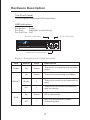
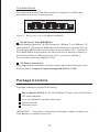
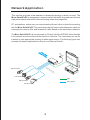
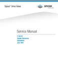
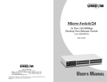
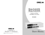
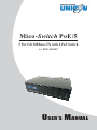
TM
Mico- Switch PoE/5
5 Port 10/100Base-TX with 4 PoE Switch
PN: POE-35055T
USER’S MANUAL
Introduction
Power-over-Ethernet (PoE) eliminates the need to run DC power to other devices on a
wired LAN. Using a Power-over-Ethernet system, installers need to run only a single
Category 5 Ethernet cable that carries both power and data to each device. This allows
greater flexibility in the locating of network devices and, in many cases, significantly
decreases installation costs.
There are two system components in PoE - the PSE (Power Sourcing Equipment) and
the PD (Powered Device). The IEEE 802.3af/at specification defines PSE as a device that
inserts power onto an Ethernet cable. The PSE may be located at the switch (Endspan
configuration). or it may be a separate device located between the switch and the PD
(Midspan configuration). The PD is the natural termination of this link, receiving the power,
and could be an IP phone, a WLAN access point, or any other IP device that requies
power. The current is transmitted over two of the four twisted pairs of wires in a
Category-5 cable.
Power-over-Ethernet follows the IEEE 802.3af/at specification and is completely compatible
with existing Ethernet switches and networked devices. Because the Power Sourcing
Equipment (PSE) tests whether a networked device is PoE-capable, power is never
transmitted unless a Powered Device is at the other end of the cable. It also continues to
monitor the channel. If the Powered Device does not draw a minimum current, because it
has been unplugged or physically turned off, the PSE shuts down the power to that port.
Optionally, the standard permits Powered Devices to signal th the PSEs exactly how
much power they need.
Unicom’s Micro-SwitchPoE/5 Switch is a multi-port switch that can be used to build
high-performance switched workgroup networks. This switch is a store-and-forward
device that offers low latency for high-speed networking. It also features a
“store-and-forward” switching scheme that allows the switch to auto-learn and store
source addresses in a 1K-entry MAC address table. The switch is targeted at workgroup,
department or backbone computing environments.
1
Hardware Description
The Front Panel
The front panel consists of LED Indications.
LED Indicators
Per Device:
Power
Per Port:
LINK/ACT (Link/Activity)
Per PoE Port: PoE
Power Indicator
PoE Indicator
Global Systems Solutions
UNIC M
Mico-Switch PoE /5
PWR
PoE
5 Port 10/100Base-TX with 4 Port PoE Switch
LINK/ACT Indicators
Figure 2. Front panel view of LED indications
LED
Status
Color
Description
Power
On
Green
The switch is supplied with suitable
power.
On
Green
The port is connecting at 10Mbps.
Blinks
-
The port is receiving or transmitting
data.
Off
-
The port is not linked successfully
with the device.
On
Green
Off
-
LINK/ACT
PD is connected
PoE
No PD is connected or power
forwarding fails
2
The Real Panel
The rear panel view of the Mico-Switch/5 consists of a DC power
connector and 5 auto-sensing ports.
PoE
5
4
3
2
1
DC IN
Figure 3. Rear panel view of the Micro-Switch/5
RJ-45 Ports ( Auto MDI/MDIX )
5 auto-sensing ports of 10/100 N-way for 10Base-T or 100Base-TX
connections. [ In general, MDI means connecting to another Hub or
Switch while MDIX means connecting to a workstation or PC. Therefore,
Auto MDI/MDIX means that you can connect to another Switch or
workstation without changing pin-to-pin or crossover cabling. ]
Four of these ports can supply to PDs.
DC Power Connector
Plug the female connector into the switch and male connector into
a power outlet. Supports input voltages 48 VDC at 1.35A.
Package Contents
Package contents include the following:
Micro-Switch PoE/5; 5 Port 10/100Base-TX with 4 port PoE Switch
DC power adapter
Four (4) adhesive-backed rubber feet
User’s manual
Warranty card
IMPORTANT: If any piece is missing or damaged, please contact your
local dealer or reseller for service.
3
Network Application
This section provides a few samples of network topology in which is used. The
Micro-SwitchPoE/5 is designed as a segment switch that has a large address table and
high performance to deal with interconnecting networking segments.
PC, workstations, and servers can communicate with each other by directly connecting
with the Micro-SwitchPoE/5 . The switch automatically learns nodes addresses, which are
subsequently used to filter and forward all traffic based on the destination address.
The Micro-SwitchPoE/5 can provide power to PDs that follow the IEEE 802.3af/at standard
in the network and solves the problem of position limitation. The network devices can be
installed in more appropriate position for better performance. The following figure is an
example of network application for Power over Ethernet Switch.
E h
Po witc
rts t S
Po e
4 ern
h
Et
Po
we
r
Mo
ni
to
r
5
4
3
2
1
D
C
IN
5
VR
at
N
C
PoE IP Camera
/5
e/
6
C
ab
le
PoE IP Camera
Data
PoE IP Camera
Data + Power
PoE IP Camera
4
Troubleshooting
This section is intended to help solve the most common issues with the Micro-SwitchPoE/5
Incorrect connections
Every port on this switch can automatically detect either straight or crossover cables when
you link it with other Ethernet devices but other devices may demand a specific cable type
(depending on the device). Choose the appropriate cable to connect between the units.
The RJ-45 connector should use correct UTP or STP cable, 10/100Mbps port use 2-pairs
twisted cable. If th RJ-45 connector is not correctly pinned then the link will fail.
Faulty or loose cables
Look for loose or obviously faulty connections. If they appear to be OK, make sure the
connections are snug. If that does not correct the problem, try a different cable.
Non-standard cables
Non-standard and miswired cables may cause numerous network collisions and other
network problems, and can seriously impair network performance. A cable tester is the
recommended tool for network installation.
RJ-45 ports: Use unshielded twisted-pair (UTP) or shield twisted-pair (STP) cable for
RJ-45 connections: 100Ω Category 3, 4 or 5 cable for 10Mbps connections, 100Ω
Category 5 cable for 100Mpbs connections, or 100Ω Category 5e / above cable for
1000Mbps connections. Also be sure that length of any twisted-pair connection does
not exceed 100 meters (328 feet). We suggest using Category 5e cable when connection
to power a device.
Improper Network Topologies
It is important to make sure that you have a valid network topology. Common topology
faults include excessive cable length and too many repeaters (hubs) between end nodes.
In addition, you should make sure that your network topology contains no data path loops.
Between any two ends nodes, there should be only one active cabling path at any time.
Data path loops will cause broadcast storms that will severely impact your network performance.
Diagnosing LED Indicators
To assist in identifying problems, the switch can be easily monitored through panel
indicators, which describe common problems the user may encounter and where the user
can find possible solutions. If the LED display detection isn’t correct, please unplug then
plug in the cable again.
If the power indicator does not light when the power cord in plugged in, you may have a
problem with the power outlet or power connections, power losses, or surges at power
outlet. If the problem still cannot be resolved, please contact the local dealer for assistance.
5
Product Specifications
Standard
Compliance:
IEEE 802.3 10Base-T Ethernet
IEEE 802.3u 100Base-TX Fast Ethernet
IEEE 802.3x Flow Control
IEEE 802.3af/at Power over Ethernet
Transfer Rate:
14,880 pps for 10Mbps
148,800 pps for 100Mbps
Connector:
10/100TX: 5 x RJ-45 with auto MDI/MDI-X funtions;
Port 2~5 support PoE injector function
PoE pin assignmnet: V+ (RJ45 Pin 4, 5), V- (RJ45 Pin 7, 8)
1K MAC address table
MAC Address:
Switching capacity: 1G
LED Indicator:
Per port: Link/Activity
Per PoE port: PoE
Per unit: Power
Network Cable:
2-pair UTP Cat. 5e cable (100m),
EIA/TIA-568 100-ohm STP (100M)
Dimension:
92mm x 68mm x 24mm (W x D x H)
Ventilation:
Fanless
Operating Temp:
0℃ to 45℃ ( 32℉ to 113℉)
Operating Humidity: 10% to 90% (Non-condensing)
Power Supply:
External power supply
Input: AC100~240V; Output: DC 48V, 1.35A
Power Consumption: 65 Watt
EMI:
FCC Class B, CE
FCC Statement
This equipment has been tested and found to comply with the limits for a class B
device, pursuant to part 15 of the FCC rules. These limits are designed to provide
reasonable protection against harmful interference in a commercial installation.
This equipment generates, uses and can radiate radio frequency energy and, if not
installed and used in accordance with instructions, may cause harmful
interference with radio communications. Operation of this equipment in a
residential area is likely to cause harmful interference, in which case, the user will
be required to correct the interference at the user’s expense.
6
TM
565 Brea Canyon Rd., Ste A
Walnut, CA 91789
Phone: 626.964.7873
www.unicomlink.com
Fax: 626.964.7880
e-mail: [email protected]
@UNICOM 2007. UNICOM and “A Network Systems Solution” are trademarks of UNICOM Electric, Inc.
All rights reserved. Specifications subject to change without notice.
Rev: 11.12