1
OB416_--1qxp
12/2/05 4:27 PM
Page 1
Revision:A
●
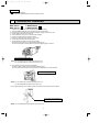
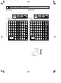
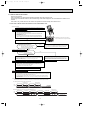
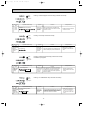
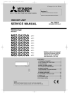
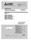
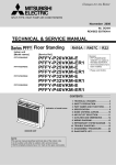
SPLIT-TYPE, HEAT PUMP AIR CONDITIONERS
A2
model has been added.
Please void OB416.
INDOOR UNIT
No. OB416
SERVICE MANUAL
REVISED EDITION-A
Wireless type
Models
MSZ-FA25VA
MSZ-FA25VA
MSZ-FA35VA
MSZ-FA35VA
-
A1
A2
A1
A2
Outdoor unit service manual
MUZ-FA series (OB417)
MXZ-A·VA series (OB447)
MXZ-8A140VA1 (OC316)
CONTENTS
MSZ-FA25VA
MSZ-FA35VA
1. TECHNICAL CHANGES ····································2
2. PART NAMES AND FUNCTIONS······················3
3. SPECIFICATION·················································5
4. NOISE CRITERIA CURVES ·······························6
5. OUTLINES AND DIMENSIONS ·························7
6. WIRING DIAGRAM ············································8
7. REFRIGERANT SYSTEM DIAGRAM ················8
8. SERVICE FUNCTIONS ······································9
9. TROUBLESHOOTING······································11
10. DISASSEMBLY INSTRUCTIONS·····················31
11. PARTS LIST······················································35
12. OPTIONAL PARTS···········································38
NOTE:
This service manual describes technical data of the indoor units.
OB416_--1qxp
12/2/05 4:27 PM
Page 2
Revision:A
•
A2 model has been added.
Color of BOX and CORNER BOX has been changed to white.
1
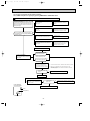
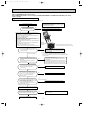
TECHNICAL CHANGES
MSZ-A09YV - A1
MSZ-A12YV - A1
➔ MSZ-FA25VA - A1
➔ MSZ-FA35VA - A1
1. Indication of capacity has been changed.(BTU base ➔kW base)
2. Controller method between indoor and outdoor has been changed.
3. Power supply method has been changed (change to supply from outdoor unit).
4. Power supply cord has been removed.
5. Indoor electronic control P.C. board has been changed.
6. Position of terminal block has been changed.
7. Indoor fan motor has been changed. ( AC ➔ DC)
8. Indoor heat exchanger has been changed.
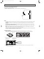
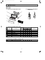
9. The horizontal vane motor unit has been changed.
An external gear is added to the generalized stepping motor.
The unit is structured so that the driving torque and stopping torque increase.
Generalized stepping motor
NOTE: Do not remove the vane motor from the motor unit.
Do not disassemble the horizontal vane motor unit.
10. The vertical vane motor unit has been added.
An external gear is added to the generalized stepping motor.
The unit is structured so that the driving torque and stopping torque would increase.
Generalized stepping motor
NOTE: Do not remove the vane motor from the motor unit.
Do not disassemble the vertical vane motor unit.
11. Front panel driving motor unit which opens and closes the front panel has been added.
Front panel opening/closing
output gear
NOTE: Do not disassemble the front panel driving motor unit.
2
OB416_--1qxp
12/2/05 4:27 PM
Page 3
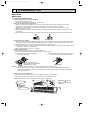
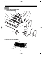
12. PLASMA DEODORIZING/AIR PURIFYING filter units have been added.
13. i-see Sensor has been added.
(i-see control operation and AREA setting have been added.)
14. Air cleaning filer has been removed.
15. Signal of remote controller has been changed. (It is not available for the conventional models.)
16. Symbol on terminal block has been changed (to S1/S2/S3).
MSZ-FA25VA- A1 ➔ MSZ-FA25VA- A2
MSZ-FA35VA- A1 ➔ MSZ-FA35VA- A2
1. Color of BOX and CORNER BOX has been changed to white.
2
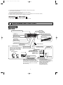
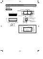
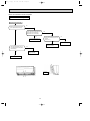
PART NAMES AND FUNCTIONS
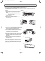
INDOOR UNIT
MSZ-FA25VA
MSZ-FA35VA
Air inlet
PLASMA AIR PURIFYING filter
Front panel
Panel
PLASMA DEODORIZING filter
Heat exchanger
Fan guard
Anti-mold air filter
Air outlet
Vertical vane
Horizontal vane
Remote controller
Line flow fan
Auto front panel
When the unit starts operating, the
front panel opens automatically to
draw in air. When the unit stops
operating, the front panel closes
automatically.
Display section
Operation section
(When the front panel is opened)
OPERATION
INDICATOR
POWER lamp
PLASMA/WASH lamp
Auto front panel
AREA lamp
Emergency operation
switch
<Open>
<Closed>
WASH reset switch
Remote control
receiving section
AREA lamp indicate AREA setting
In AREA setting, the horizontal air flow
direction changes automatically according
to the detection of i-see Sensor which detects
the floor/ wall temperature to air-condition
the room evenly.
3
i-see Sensor
i-see control operation
i-see sensor constantly measure
floor/wall temperature to automatically
adjust to the set temperature by
estimating the temperature
actually perceived by a
person inside the room
("sensible temperature").
OB416_--1qxp
12/2/05 4:27 PM
Page 4
MSZ-FA25VA
MSZ-FA35VA
ACCESSORIES
1
Installation plate
1
2
Installation plate fixing screw 4 o 25 mm
5
3
Remote controller holder
1
4
Fixing screw for 3 3.5 o 1.6 mm (Black)
2
5
Battery (AAA) for remote controller
2
6
Wireless remote controller
1
7
Felt tape (Used for left or left-rear piping)
1
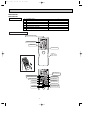
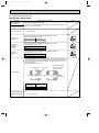
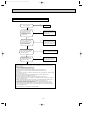
REMOTE CONTROLLER
Signal transmitting section
Operation display section
OPERATE/STOP
(ON/OFF) button
Temperature buttons
Indication of
remote controller
model is on back
Open the front lid.
(This diagram shows an overall view.)
WIDE VANE button
(Vertical vane button)
FAN SPEED CONTROL button
OPERATION SELECT button
OFF-TIMER button
ECONO COOL button
ON-TIMER button
TIME SET buttons
FORWARD button
BACKWARD button
PLASMA button
AREA button
CLOCK SET button
i-see button
VANE CONTROL button
(Horizontal vane button)
RESET button
4
OB416_--1qxp
12/2/05 4:27 PM
3
Page 5
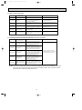
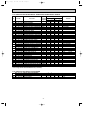
SPECIFICATION
Indoor model
MSZ-FA25VA
Function
Cooling
MSZ-FA35VA
Cooling
Heating
Single phase
230V,50Hz
Power supply
Air flow(Super High)
Air flow(High/Med./Low)
Power outlet
Running current ✽1
Power input ✽1
Power factor ✽1
Fan motor current ✽1
Model
Fan motor
Dimensions WOHOD
Weight
Air direction
Sound level(Super High)
Sound level(High/Med./Low)
Fan speed(Super High)
Fan speed(High/Med./Low)
Fan speed regulator
Special
remarks
Electrical
data
Capacity
K /h
K /h
A
A
W
%
A
mm
kg
dB(A)
dB(A)
rpm
rpm
Remote controller model
594
474/354/252
Heating
Single phase
230V,50Hz
594
474/354/258
612
498/384/264
612
498/384/276
10
0.25
33
57
0.25
RC0J40-EB or RC0J30-CC
780O298O198
10
4
42
36/29/21
1,220
1,250
1,010/800/610
1,050/850/640
4
KM05A
10
0.25
33
57
0.25
RC0J40-EB or RC0J30-CC
780O298O198
10
4
42
36/29/22
1,220
1,250
1,010/800/630
1,050/850/660
4
KM05A
MSZ-FA25VA
MSZ-FA35VA
When outdoor unit is MXZ-8A140VA1.
Indoor model
Function
Special
remarks
Air flow(Super High)
Capacity
Air flow(High/Med./Low)
Sound level(Super High)
Sound level(High/Med./Low)
Fan speed(Super High)
Fan speed(High/Med./Low)
K /h
K /h
dB(A)
dB(A)
rpm
rpm
Cooling
546
450/348/252
Cooling
Heating
540
420/372/264
516/390/258
522/402/276
42
36/29/22
1,300
1,080/860/630
1,090/880/660
42
36/29/21
1,130
960/790/610
1,120
910/830/640
NOTE : Test conditions are based on AS/NZS 3823.1.1.
Cooling : Indoor Dry-bulb temperature 27:Wet-bulb
Outdoor Dry-bulb temperature 35:Wet-bulb
Heating : Indoor Dry-bulb temperature 20:Wet-bulb
Outdoor Dry-bulb temperature 7: Wet-bulb
Refrigerant piping length (one way): 5m
✽1 Measured under rated operating frequency.
temperature
temperature
temperature
temperature
Heating
642
19:
24:
15:
6:
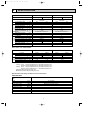
Specifications and rating conditions of main electric parts
INDOOR UNIT
Item
Fuse
(F11)
T3.15AL250V
Front panel driving motor
(MP)
NSEJ001DA1 12V DC 100" (at 25˚C)
i-see Sensor motor
(MT)
Horizontal vane motor
Vertical vane motor
Varistor
MP20Z 12V DC 300" (at 25˚C)
(MV1)
MSBPC20M16 12V DC 250" (at 25˚C)
(MV2)
MSBPC20M11 12V DC 300" (at 25˚C)
(NR11)
ERZV14D471
i-see Sensor
(RR)
A2TPMI334F0V50HSOBA060P5L1J4S 5V DC
Terminal block
(TB)
3P
5
OB416_--1qxp
4
12/2/05 4:27 PM
Page 6
NOISE CRITERIA CURVES
MSZ-FA25VA
MSZ-FA35VA
FAN SPEED FUNCTION
Super High
SPL(dB(A))
COOLING
42
HEATING
42
LINE
FAN SPEED FUNCTION
Super High
80
70
NC-70
60
NC-60
50
NC-50
40
NC-40
30
NC-30
20
10
APPROXIMATE
THRESHOLD OF
HEARING FOR
CONTINUOUS
NOISE
63
125
500
1000
2000
4000
HEATING
42
LINE
80
70
NC-70
60
NC-60
50
NC-50
40
NC-40
30
NC-30
20
NC-20
250
42
Test conditions,
Cooling : Dry-bulb temperature 27: Wet-bulb temperature 19:
Heating : Dry-bulb temperature 20: Wet-bulb temperature 15:
90
OCTAVE BAND SOUND PRESSURE LEVEL, 0dB=20µPa
OCTAVE BAND SOUND PRESSURE LEVEL, 0dB=20µPa
Test conditions,
Cooling : Dry-bulb temperature 27: Wet-bulb temperature 19:
Heating : Dry-bulb temperature 20: Wet-bulb temperature 15:
90
SPL(dB(A))
COOLING
10
8000
APPROXIMATE
THRESHOLD OF
HEARING FOR
CONTINUOUS
NOISE
63
BAND CENTER FREQUENCIES, Hz
125
NC-20
250
500
1000
2000
4000
BAND CENTER FREQUENCIES, Hz
INDOORUNIT
WALL
1m
0.8m
MICROPHONE
6
8000
12/2/05 4:27 PM
5
Page 7
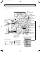
OUTLINES AND DIMENSIONS
Unit : mm
11o26 Oblong hole
155
55
155
335
Indoor unit
Wall hole [65
5
100
298
7 or more
198
624.5
102
Installation plate
Liquid line [6.35 - 0.5m
Gas line [9.52 - 0.43m
Insulation [35 O.D
[19 I.D
{
Drain hose [16
(Connected part O.D)
90
Insulation [28
106
19
Air out
159
58
70
320
Air in
3
41.5
780
53.5
55
215
Installation plate
11o20 Oblong hole
225
225
214
234
273.5
287.5
55
42.5
INDOOR UNIT
14
MSZ-FA25VA
MSZ-FA35VA
Required space (Indoor unit)
Wireless remote controller
7
75 or more
55 or morew
10 or more
75 or more
wIn case of left, left back, or
left under piping (using spacer),
113 or more
OB416_--1qxp
OB416_--1qxp
12/2/05 4:28 PM
6
Page 8
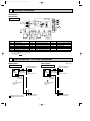
WIRING DIAGRAM
MSZ-FA25VA
MSZ-FA35VA
INDOOR UNIT
230V~
TB
S1
S2
TO OUTDOOR
UNIT
CONNECTING
12-24V
S3
BLK
TAB3
INDOOR ELECTRONIC
CONTROL P.C. BOARD
F11
DB111
BLU
RED
2
1
4
CN
111
NR11
1
2
3
4
5
6
LD104
GRN
5
LD
101(A)
CN
1R1
5
2
INTERLOCK
SWITCH(FAN)
MV1 MV2
SYMBOL
DB111
F11
MF
MP
MT
MV1
CN
110
LD
105(T)
3
8
4
5
SW P.C.
BOARD
POWER MONITOR
RECEIVER P.C. BOARD
MT
CN
1T2
CN
1T1
RR
3
3
PLASMA_A
PLASMA_D
RT12
1
T111
CN201
CN
151
RT13
CN 3
112 2
CN
1U1
RT11
RED
BLK
WHT
YLW
BLU
5
MF
CN211
5
2
MP
SAFETY DEVICE
(PLASMA UNIT)
SYMBOL
NAME
NAME
NAME
SYMBOL
VANE MOTOR (VERTICAL)
MV2
DIODE STACK
RT12 INDOOR COIL THERMISTOR (MAIN)
NR11 VARISTOR
FUSE (T3.15AL250V)
RT13 INDOOR COIL THERMISTOR (SUB)
PLASMA_A PLASMA AIR PURIFYING FILTER UNIT
TRANSFORMER
INDOOR FAN MOTOR
T111
FRONT PANEL DRIVING MOTOR PLASMA_D PLASMA DEODORIZING FILTER UNIT
TERMINAL BLOCK
TB
i-see Sensor
RR
i-see Sensor MOTOR
VANE MOTOR (HORIZONTAL) RT11 ROOM TEMPERATURE THERMISTOR
NOTE:1. About the outdoor side electric wiring refer to the outdoor unit electric wiring diagram for servicing.
2. Use copper conductors only. (For field wiring)
3. Symbols below indicate.
/: Terminal block,
: Connector
7
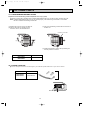
REFRIGERANT SYSTEM DIAGRAM
MSZ-FA25VA
MSZ-FA35VA
INDOOR UNIT
Indoor
heat
exchanger
INDOOR UNIT
Refrigerant pipe [9.52
(with heat insulator)
Indoor coil
thermistor
RT12(main)
Indoor
heat
exchanger
Flared connection
Indoor coil
thermistor
RT13(sub)
Indoor coil
thermistor
RT12(main)
Refrigerant pipe [9.52
(with heat insulator)
Flared connection
Indoor coil
thermistor
RT13(sub)
Room temperature
thermistor
RT11
Room temperature
thermistor
RT11
Flared connection
Refrigerant flow in cooling
Refrigerant flow in heating
Unit : mm
Flared connection
Refrigerant pipe [6.35
(with heat insulator)
Refrigerant pipe [6.35
(with heat insulator)
8
OB416_--1qxp
12/2/05 4:28 PM
8
Page 9
SERVICE FUNCTIONS
MSZ-FA25VA
MSZ-FA35VA
8-1. TIMER SHORT MODE
For service, set time can be shortened by short circuit of JPG and JPS the electronic control P.C. board.
The time will be shortened as follows. (Refer to 9-7.)
Set time : 1-minute ➔ 1-second
Set time : 3-minute ➔ 3-second (It takes 3 minutes for the compressor to start operation. However, the starting time is
shortened by short circuit of JPG and JPS.)
8-2. P.C. BOARD MODIFICATION FOR INDIVIDUAL OPERATION
A maximum of 4 indoor units with wireless remote controllers can be used in a room.
In this case, to operate each indoor unit individually by each remote controller, P.C. boards of remote controller must be
modified according to the number of the indoor unit.
How to modify the remote controller P.C. board
Remove batteries before modification.
The board has a print as shown below :
NOTE : For remodelling, take out
the batteries and press the
OPERATE/STOP(ON/OFF)
button twice or 3 times at
first.
After finish remodelling,
put back the batteries then
press the RESET button.
J1
J2
The P.C. board has the print “J1” and “J2”. Solder “J1” and “J2” according to the number of indoor unit as shown in Table 1.
After modification, press the RESET button.
Table 1
1 unit operation
2 units operation
3 units operation
4 units operation
No. 1 unit
No modification
Same as at left
Same as at left
Same as at left
No. 2 unit
–
Solder J1
Same as at left
Same as at left
No. 3 unit
–
–
Solder J2
Same as at left
No. 4 unit
–
–
–
Solder both J1 and J2
How to set the remote controller exclusively for particular indoor unit.
After you turn the breaker ON, the first remote controller that sends the signal to the indoor unit will be regarded as the remote
controller for the indoor unit.
The indoor unit will only accepts the signal from the remote controller that has been assigned to the indoor unit once they are
set.
The setting will be cancelled if the breaker has turned off, or the power supply has shut down.
Please conduct the above setting once again after the power has restored.
8-3. AUTO RESTART FUNCTION
When the indoor unit is controlled with the remote controller, the operation mode, the set temperature, and the fan speed
are memorized by the indoor electronic control P.C. board. The “AUTO RESTART FUNCTION” sets to work the moment
power has restored after power failure. Then, the unit will restart automatically.
Operation
1 If the main power has been cut, the operation settings remain.
2 After the power is restored, the unit restarts automatically according to the memory.
(However, it takes at least 3 minutes for the compressor to start running.)
9
OB416_--1qxp
12/2/05 4:28 PM
Page 10
CN151 CN1T2 CN1T1 CN112
IC156
CN212
CN130
CN1R1 CN211
How to release “AUTO RESTART FUNCTION”
1Turn off the main power for the unit.
2Solder the Jumper wire JR07 on the indoor electronic control P.C. board. (Refer to 9-7.)
JR07
NOTE:
• The operation settings are memorized when 10 seconds have passed after the indoor unit was operated with the remote
controller.
• If main power is turned OFF or a power failure occurs while AUTO START/STOP timer is active, the timer setting is
cancelled.
• If the unit has been off with the remote controller before power failure, the auto restart function does not works as the
power button of the remote controller is off.
• To prevent breaker off due to the rush of starting current, systematize other home appliance not to turn on at the same
time.
• When some air conditioners are connected to the same supply system, if they are operated before power failure, the
starting current of all the compressors may flow simultaneously at restart.
Therefore, the special counter-measures are required to prevent the main voltage-drop or the rush of the starting current
by adding to the system that allows the units to start one by one.
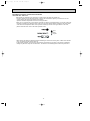
8-4. Remote controller
Be sure to set the slide switch inside the remote controller to an appropriate position in accordance with the
installed position of the indoor unit. If the switch is not set correctly, the air conditioner may not function properly.
Side swich
Area
Position of
the slide
switch
Display on
the remote
controller
Left
Center
Right
Where is the indoor unit installed in your room?
Installed at left , if the
distance is not more
than 50 cm.
(Left)
Installed at right , if the
distance is not more
than 50 cm.
(Center)
(Right)
Is the indoor unit installed at right, left or
center?
NOTE:If the indoor unit is installed more than 50 cm away from the side walls, cabinets or other nearby objects, set the slide
switch to the “center” position.
10
OB416_--1qxp
12/2/05 4:28 PM
9
Page 11
TROUBLESHOOTING
MSZ-FA25VA
MSZ-FA35VA
9-1. Cautions on troubleshooting
1. Before troubleshooting, check the following:
1) Check the power supply voltage.
2) Check the indoor/outdoor connecting wire for mis-wiring.
2. Take care the following during servicing.
1) Before servicing the air conditioner, be sure to turn off the unit first with the remote controller, and then after
confirming the horizontal vane is closed, turn off the breaker and / or disconnect the power plug.
2) Be sure to turn OFF the power supply before removing the front panel, the cabinet, the top panel, and the
electronic control P.C. board.
3) When removing the electronic control P.C. board, hold the edge of the board with care NOT to apply stress on the
components.
4) When connecting or disconnecting the connectors, hold the housing of the connector. DO NOT pull the lead wires.
Lead wiring
Housing point
3. Troubleshooting procedure
1) First, check if the OPERATION INDICATOR lamp on the indoor unit is flashing on and off to indicate an abnormality.
To make sure, check how many times the abnormality indication is flashing on and off before starting service work.
2) Before servicing check that the connector and terminal are connected properly.
3) If the electronic control P.C. board is supposed to be defective, check the copper foil pattern for disconnection and the
components for bursting and discoloration.
4) When troubleshooting, refer to 9-2., 9-3. and 9-4.
4. How to replace batteries
Weak batteries may cause the remote controller malfunction.
In this case, replace the batteries to operate the remote controller normally.
2 Press RESET button with tip end of ball point pen
or the like, and then use the remote controller.
1 Remove the front lid and insert batteries.
Then reattach the front lid.
Insert the negative pole of the
batteries first. Check if the polarity
of the batteries are correct.
RESET button
NOTE : 1. If RESET button is not pressed, the remote controller may not operate correctly.
2. This remote controller has a circuit to automatically reset the microcomputer when batteries are replaced.
This function is equipped to prevent the microcomputer from malfunctioning due to the voltage drop caused by
the battery replacement.
5. How to install the horizontal vane
If horizontal vane is not installed correctly, All of the operation indicator lamps will blink.
In this case, install the horizontal vane correctly by following the procedures 1 to 2.
NOTE: Before installation of the horizontal vane, turn OFF the power supply.
1
2
Stopper
In procedure 2 lock the
stoppers until they click
into place.
Left
Lock.
Insert this end first.
11
OB416_--1qxp
12/2/05 4:28 PM
Page 12
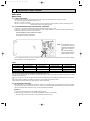
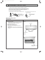
6. How to remove and install PLASMA DEODORIZING / AIR PURIFYING filter units
If PLASMA/WASH lamp on the indoor unit blinks, clean the filters as soon as possible. The lamp will start blinking when
accumulated operating time exceeds 330 hours.
<Remove>
(1) Switch the indoor unit OFF with the remote controller and
disconnect the power supply plug and/ or turn OFF the
breaker.
NOTE: Otherwise, you may get injured since PLASMA
DEODORIZING/AIR PURIFYING filter units are
charged with high voltage.
(2) Hold the knobs on both sides of the front panel and lift the
panel up until its level.
(3) Remove the anti-mold air filter.(See Figure 1.)
(4) Remove PLASMA DEODORIZING/AIR PURIFYING filter
units. (See Figure 2.)
Figure 1.
Figure 2.
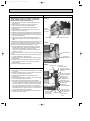
<Install>
Install PLASMA DEODORIZING/AIR PURIFYING filter units by following the removal procedure in reverse.
(1) Insert the top of PLASMA DEODORIZING/AIR PURIFYING filter
units into the aperture in the plasma element holder.
(See Figure 3.)
(2) Push in PLASMA DEODORIZING/AIR PURIFYING filter units
until they click into place.
•The front panel does not close if PLASMA DEODORIZING/AIR
PURIFYING filter units are not installed properly.
(3) Install the anti-mold air filter.
(4) Connect the power supply plug and/or turn ON the breaker.
(5) Press WASH reset switch. A short “beep” is heard and the blinks
of PLASMA/WASH lamp will be cancelled. Make sure PLASMA/
WASH lamp is not blinking at the start of operation next time.
(See Figure 4.)
(6) Hold both sides of the front panel and close the front panel.
(7) Press the 3 positions on the front panel as indicated by the
arrows.(See Figure 5.)
Figure 3.
Plasma
element
holder
Figure 4.
E.O.
SW
NOTE:
Install PLASMA DEODORIZING/AIR PURIFYING filter units only
when they are completely dry. If the filter unit remains wet,
PLASMA/WASH lamp may blink and the plasma function may be
disabled.(When PLASMA DEODORIZING/AIR PURIFYING filter
units are cleaned.)
WASH
reset
Figure 5.
12
OB416_--1qxp
12/2/05 4:28 PM
Page 13
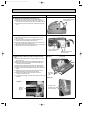
INFORMATION FOR MULTI SYSTEM AIR CONDITIONER
OUTDOOR UNIT : MXZ series
Multi system air conditioner can connect two or more indoor units with one outdoor unit.
•Unit won’t operate in case the total capacity of indoor units exceeds the capacity of outdoor units. Do not
connect indoor units beyond the outdoor unit capacity.
Operation indicator lamp flashes as shown in the figure below.
•When you try to operate two or more indoor units with one outdoor unit simultaneously, one for the cooling and
the other for heating, the operation mode of the indoor unit that operates earlier is selected. The other indoor
units which start the operation later cannot operate, indicating as shown in the figure below. In this case,
please set all the indoor units to the same operation mode.
Lighted
Blinking
Not lighted
•When indoor units start the operation while the defrosting of outdoor unit is being done, it takes a few minutes
(max. 10 minutes) to blow out the warm air.
•In the heating operation, though indoor unit that does not operate may get warm or the sound of refrigerant
flowing may be heard, they are not malfunction. The reason is that the refrigerant continuously flows into it.
13
OB416_--1qxp
12/2/05 4:28 PM
Page 14
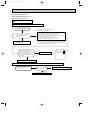
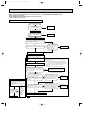
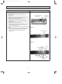
9-2. Failure mode recall function
Outline of the function
This air conditioner can memorize the abnormal condition which has occurred once.
Even though LED indication listed on the troubleshooting check table disappears, the memorized failure details can be
recalled.
This mode is very useful when the unit needs to be repaired for the abnormality which doesn't recur.
1. Flow chart of failure mode recall function for the indoor/outdoor unit
Operational procedure
The cause of abnormality cannot be found because the abnormality doesn't recur.
Setting up the failure mode recall function
Turn ON the power supply.
<Preparation of the remote controller>
1 While pressing both OPERATION SELECT
button and TOO COOL button on the remote controller at the same time, press
RESET button.
2 First, release RESET button.
And release the other two buttons after all LCD except the set temperature in
operation display section of the remote controller is displayed after 3 seconds.
W1. Regardless of normal or abnormal, a short
beep is emitted once as the signal is received.
Press OPERATE/STOP(ON/OFF) button of the remote controller (the set temperature
is displayed) with the remote controller headed towards the indoor unit. W1
No
(OFF)
Does POWER lamp on the indoor
unit blink at the interval of 0.5 seconds?
Blinks: Either indoor or outdoor unit is abnormal.
Beep are emitted at the same timing
as the blinking of POWER lamp. W2
Judgment of indoor/outdoor abnormality
The plasma or outdoor unit might be abnormal because there are some
abnormalities that can't be recalled with this way.
Confirm if plasma unit or outdoor unit is abnormal according to the flow
chart of the plasma unit or detailed outdoor unit failure mode recall
function.
Yes
(Blinks)
Before blinking, does POWER
lamp stay ON for 3 seconds?
Stays ON for 3 seconds (without beep):
The outdoor unit is abnormal.
Yes
No
The indoor unit is abnormal.
Check the blinking pattern, and confirm the abnormal point with the indoor unit
failure mode table (9-2.4.).
Make sure to check at least two consecutive blinking cycles. W2
The outdoor unit is abnormal.
Check the blinking pattern, and confirm the abnormal point with the
outdoor unit failure mode table (Refer to outdoor unit service manual.)
Make sure to check at least two consecutive blinking cycles. W3
Releasing the failure mode recall function
Release the failure mode recall function by the following procedures. (A or B,C)
AWith the remote controller headed towards the indoor unit, press any button
that is not used in this failure mode recall function (e.g. TIMER button) .
BTurn OFF the power supply and turn ON it again.
CPress RESET button of the remote controller.
Repair the defective parts.
Deleting the abnormal memorized condition
1After repairing the unit, recall the failure mode again according to
"Setting up the failure mode recall function" mentioned above.
2Press OPERATE/STOP(ON/OFF) button of the remote controller (the set temperature is displayed)
with the remote controller headed towards the indoor unit.
3Press EMERGENCY OPERATION switch so that the memorized abnormal condition is deleted.
4Release the failure mode recall function according to "Releasing the failure mode recall function"
mentioned above.
Note1.Make sure to release the failure mode recall function once it's set up, otherwise the unit cannot operate properly.
2.If the abnormal condition is not deleted from the memory, the last abnormal condition is kept memorized.
W2. Blinking pattern when the indoor unit is abnormal:
Blinking at 0.52.5-second OFF second interval
Blinking at 0.52.5-second OFF second interval
ON
OFF
Beeps
Repeated cycle
Beeps
Repeated cycle
Beeps
Repeated cycle
W3.Blinking pattern when the outdoor unit is abnormal:
Blinking at 0.52.5-second OFF
3-second ON
second interval
2.5-second OFF
3-second ON
Blinking at 0.5second interval
ON
OFF
No beep
Repeated cycle
Beeps
No beep
Repeated cycle
14
Beeps
Repeated cycle
OB416_--1qxp
12/2/05 4:28 PM
Page 15
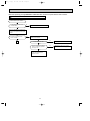
2. Flow chart of PLASMA DEODORIZING/PLASMA AIR PURIFYING power failure mode recall function
Operational procedure
The plasma unit might be abnormal.
Confirm if plasma unit is abnormal according to the following procedures.
Confirm that the remote controller is in the failure mode recall
function.
With the remote controller headed towards the indoor unit, press TOO COOL or TOO
WARM button to adjust the set temperature to 23:. W1
Does POWER lamp on the indoor
unit blink at the interval of 0.5 seconds?
Blinks: The plasma unit is abnormal.
Beep are emitted at the same timing as the
blinking of POWER lamp.
W2
W1. Regardless of normal or abnormal, a short
beep is emitted as the signal is received.
No
(OFF)
Yes
(Blinks)
The plasma unit is abnormal.
Check the blinking pattern, and refer to confirm the
abnormal point with the PLASMA DEODORIZING/PLASMA AIR
PURIFYING power failure mode table (9-2.5.).
Make sure to check at least two consecutive blinking cycles. W2
The plasma unit is normal.
Releasing the failure mode recall function
Release the failure mode recall function by the following procedures. (A or B C)
AWith the remote controller headed towards the indoor unit, press any button
that is not used in this failure mode recall function (e.g. TIMER button) .
BTurn OFF the power supply and turn ON it again.
CPress RESET button of the remote controller.
Release the failure mode recall function according to the left
mentioned procedure.
Repair the defective parts.
Deleting the abnormal memorized condition
1After repairing the unit, recall the failure mode again according to
"Setting up the failure mode recall function" mentioned above.
2Press OPERATE/STOP(ON/OFF) button of the remote controller (the set temperature is displayed)
with the remote controller headed towards the indoor unit.
3Press EMERGENCY OPERATION switch so that the memorized abnormal condition is deleted.
4Release the failure mode recall function according to "Releasing the failure mode recall function"
mentioned above.
Note1. Make sure to release the failure mode recall function once it's set up, otherwise the unit cannot operate properly.
2. If the abnormal condition is not deleted from the memory, the last abnormal condition is kept memorized.
W2.Blinking pattern when plasma unit is abnormal:
Blinking at 0.52.5-second OFF second interval
Blinking at 0.52.5-second OFF second interval
ON
OFF
Beeps
Repeated cycle
Beeps
Repeated cycle
Beeps
Repeated cycle
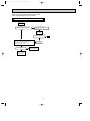
3. PLASMA DEODORIZING/PLASMA AIR PURIFYING power operation check
PLASMA DEODORIZING/PLASMA AIR PURIFYING power goes ON when PLASMA button on the remote contoller is pressed
with any set temperature displayed during failure mode recall function.
PLASMA button is pressed, the power of plasma is changed in sequence:
PLASMA DEODORIZING power goes ON
➔ PLASMA AIR PURIFYING power goes ON
➔ Cancel
Check the operation display section of the remote controller to confirm that PLASMA DEODORIZING power or PLASMA AIR
PURIFYING power is activated.
While PLASMA/WASH lamp stays OFF, it means normal.
Flashing PLASMA/WASH lamp means abnormal, the plasma power is not conducted.
PLASMA/WASH lamp
Continuously blinking
Action
Follow "Check of PLASMA DEODORIZING power" or "Check of PLASMA AIR PURIFYING power"
to identify the error.(Refer to 9-6.F or G.)
PLASMA DEODORIZING power and/or PLASMA AIR PURIFYING power control circuit on the indoor
electronic control P.C. board is out of order.(Refer to 9-6.F or G.)
NOTE: Perform the above mentioned check with the front panel closed (Refer to 9-1.6 Figure5). The SAFETY DEVICE
(PLASMA UNIT) works by opening front panel and the plasma power is cut.
2-time flash
15
OB416_--1qxp
12/2/05 4:28 PM
Page 16
4. Indoor unit failure mode table
POWER lamp
Abnormal point
(Failure mode)
Condition
Correspondence
Not lighted
Normal
–
–
1-time flash
every 0.5-second
Room temperature
thermistor
When the room temperature thermistor
short or open circuit is detected every 8
seconds during operation.
Refer to the characteristics of the room
temperature thermistor (9-7.).
2-time flash
2.5-second OFF
Indoor coil thermistor
When the indoor coil thermistor short or
open circuit is detected every 8 seconds
during operation.
Refer to the characteristics of the main
indoor coil thermistor, the sub indoor coil
thermistor (9-7.).
3-time flash
2.5-second OFF
Serial signal
When the serial signal from the outdoor unit is Refer to 9-6.D "How to check mis-wiring
not received for a maximum of 6 minutes.
and serial signal error".
11-time flash
2.5-second OFF
Indoor fan motor
When the rotational frequency feedback
signal is not emitted during the 12-seconds
indoor fan operation.
Refer to 9-6.A "Check of indoor fan
motor".
12-time flash
2.5-second OFF
Indoor control system
When it cannot properly read data in the
nonvolatile memory of the indoor electronic
control P.C. board.
Replace the indoor electronic control
P.C. board.
NOTE : Blinking patterns of this mode differ from the ones of Troubleshooting check table (9-4.).
5. PLASMA DEODORIZING/PLASMA AIR PURIFYING power failure mode table
POWER lamp
Abnormal point
(Failure mode)
Condition
1-time flash
PLASMA DEODORIZING/
PLASMA AIR PURIFYING
power control
When PLASMA DEODORIZING and/or
PLASMA AIR PURIFYING power cannot be
turned OFF even if the PLASMA operation is
turned OFF with the remote controller.
2-time flash
Spark discharge
When the voltage between CN1 3(+)
and 2(GND) on the PLASMA POWER P.C.
board (in the PLASMA DEODORIZING or
PLASMA AIR PURIFYING unit) falls below
1.6V(spark discharge judgment voltage).
3-time flash
Abnormal electric
discharge error 1
When the voltage between CN1 3(+)
and 2(GND) on the PLASMA POWER P.C.
board (in the PLASMA DEODORIZING or
PLASMA AIR PURIFYING unit) falls by 0.9V
below the normal voltage value (3V).
4-time flash
Abnormal electric
discharge error 2
When the voltage between CN1 3(+)
and 2(GND) on the PLASMA POWER P.C.
board (in the PLASMA DEODORIZING or
PLASMA AIR PURIFYING unit) falls
significantly. (0.4V / 0.5ms)
5-time flash
PLASMA DEODORIZING/
PLASMA AIR PURIFYING
power
Correspondence
Refer to 9-6.F"Check of PLASMA
DEODORIZING power" or 9-6.G"Check
of PLASMA AIR PURIFYING power".
When the voltage between CN1 3(+)
and 2(GND) on the PLASMA POWER P.C.
board (in the PLASMA DEODORIZING or
PLASMA AIR PURIFYING unit) rises above
the normal voltage value (3V).
NOTE1 : Blinking patterns of this mode differ from the ones of Troubleshooting check table (9-4.).
NOTE2 : As soon as an abnormality is detected, PLASMA DEODORIZING power and/or PLASMA AIR PURIFYING
power goes OFF, therefore measuring instrument which records the voltage wave is required in order to
perform the above mentioned voltage measurement.
16
OB416_--1qxp
12/2/05 4:28 PM
Page 17
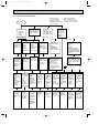
9-3. Instruction of troubleshooting
w"Test Run operation"
means the operation
within 30 minutes after
EMERGENCY OPERATION
switch is pressed.
Start
Indoor unit
operates.
Outdoor unit
doesn't
operate.
Indoor unit operates.
Outdoor unit doesn't
operate normally.
Indoor unit
doesn't receive
the signal from
remote controller.
Outdoor unit
operates only
in Test Run
operation. w
Outdoor unit
doesn't
operate
even in
Test Run
operation. w
Unit doesn't
operate
normal
operation in
COOL or
HEAT mode.
Indoor unit
operates, when
EMERGENCY
OPERATION
switch is pressed.
Check room
temperature
thermistor.
Refer to 9-7.
"Test point
diagram and
voltage".
Refer to
"How to check
inverter/
compressor".
Refer to
"Check of
R.V. coil".
Refer to 9-6.B
"Check of
remote controller
and receiver
P.C. board".
If blinking of OPERATION
INDICATOR lamp cannot
be checked, it can be checked
with failure mode recall function.
OPERATION
INDICATOR
lamp on the
indoor unit is
flashing on
and off.
Indoor unit
doesn't operate,
when
EMERGENCY
OPERATION
switch is pressed.
PLASMA/WASH lamp
2-time flash
cause:
Indoor unit
• Trouble of PLASMA
DEODORIZNG power
control and/or PLASMA
AIR sPURIFYING power
control
1. Check indoor / outdoor
connecting wire.
(Check if the power
is supplied to the
indoor unit.)
2. Refer to 9-6.C
"Check of indoor
electronic control
P.C. board and indoor
fan motor".
Refer to 9-6.F"Check of
PLASMA DEODORIZING
power" or 9-6.G"Check of
PLASMA AIR PURIFYING
power".
Refer to outdoor unit service manual.
All lamps
Flash on and off
at 0.5-second
intervals
Cause:
Indoor unit
• The horizontal
vane is not
installed
correctly.
POWER lamp
Flash on and off
at 0.5-second
intervals
Cause:
Indoor/
Outdoor unit
• Mis-wiring
or trouble
of serial signal
POWER lamp
2-time flash
Cause:
Indoor unit
• Trouble of
room temperature/
indoor coil
thermistor
POWER lamp
3-time flash
Cause:
Indoor unit
• Trouble of
indoor fan
motor
Left lamp
of AREA lamp
4-time flash
Cause:
Indoor unit
• Trouble of
indoor unit
control
system
POWER lamp
5-time flash
Cause:
Outdoor unit
• Outdoor
power
system
abnormality
POWER lamp
6-time flash
Cause:
Outdoor unit
• Trouble of
thermistor
in outdoor
unit
POWER lamp
7-time flash
Cause:
Outdoor unit
• Trouble of
outdoor
control
system
POWER lamp
14-time flash
Cause:
Outdoor unit
• Other
abnormality
Refer to 9-6.
E "Check of
installation of
the horizontal
vane".
Refer to 9-6.
D "How to
check of
mis-wiring
and serial
signal error.
Check room
temperature
thermistor
and indoor
coil thermistor.
Refer to 9-7.
"Test point
diagram and
voltage".
Refer to 9-6.
A "Check of
indoor fan
motor".
Replace the
indoor
electronic
control
P.C. board.
Refer to
"How to check
inverter/
compressor".
Refer to
"Check of
outdoor
thermistors".
Replace the
inverter P.C.
board or
the outdoor
electronic
control P.C.
board.
Check
"Flow chart of
the detailed
outdoor unit
failure mode
recall function."
17
OB416_--1qxp
12/2/05 4:28 PM
Page 18
9-4. Troubleshooting check table
Before taking measures, make sure that the symptom reappears for accurate troubleshooting.
When the indoor unit has started operation and the following detection method has detected an abnormality (the first
detection after the power ON), the indoor electronic control P.C. board turns OFF the indoor fan motor with
OPERATION INDICATOR lamp flashing.
Lighted
· Flashing of POWER lamp indicates abnormalities.
Blinking
Not lighted
No.
Abnormal
point
1
Mis-Wiring
or serial
signal
Operation indicator lamp
POWER lamp flashes.
0.5-second ON
Symptom
Condition
Correspondence
Outdoor unit
does not
operate.
When the serial signal form the outdoor unit is
not received for a maximum of 6 minutes.
• Refer to 9-6.D "How to check
mis-wiring and serial signal
error".
0.5-second OFF
2
3
4
Outdoor
control
system
POWER lamp lights up
Indoor coil
thermistor
POWER lamp flashes.
2-time flash
Room
temperature
thermistor
Indoor fan
motor
When it cannot properly read data in the
nonvolatile memory of the inverter P.C. board
or the outdoor electronic control P.C. board.
• Check the blinking pattern of
the LED on the inverter P.C.
board or the outdoor
electronic control P.C. board.
When the indoor coil or the room temperature
thermistor is short or open circuit.
• Refer to 9-7.the
characteristics of indoor coil
thermistor, and the room
temperature thermistor.
Indoor unit
and outdoor
unit do not
operate.
When the rotational frequency feedback
signal is not emit during the indoor fan
operation.
• Refer to 9-6.A "Check of
indoor fan motor".
Indoor unit
and outdoor
unit do not
operate.
When it consecutively occurs 3 times that the
compressor stops for overcurrent protection or
start-up failure protection within 1 minute after
start-up.
• Refer to "How to check of
inverter/compressor".
Refer to outdoor unit service
manual.
• Check the stop valve.
Indoor unit
and outdoor
unit do not
operate.
When the outdoor thermistors short or open
circuit during the compressor operation.
• Refer to "Check of outdoor
thermistor".
Refer to outdoor unit service
manual.
Indoor unit
and outdoor
unit do not
operate.
When it cannot properly read data in the
nonvolatile memory of the inverter P.C. board
or the outdoor electronic control P.C. board.
• Replace the inverter P.C.
board or the outdoor
electronic control P.C. board.
Refer to outdoor unit service
manual.
Indoor unit
and outdoor
unit do not
operate.
An abnormality other than above mentioned is
detected.
• Confirm the abnormality in
detail using the failure mode
recall function for outdoor unit.
Outdoor unit
does not
operate.
Indoor unit
and outdoor
unit do not
operate.
2.5-second OFF
POWER lamp flashes.
3-time flash
2.5-second OFF
5
Outdoor
power
system
POWER lamp flashes.
5-time flash
2.5-second OFF
POWER lamp flashes.
6-time flash
6
Outdoor
thermistors
2.5-second OFF
7
Outdoor
control
system
POWER lamp flashes.
7-time flash
2.5-second OFF
8 Other
abnonmality
POWER lamp flashes.
14-time flash
2.5-second OFF
18
OB416_--1qxp
12/2/05 4:28 PM
Page 19
Lighted
· Flashing of AREA lamp(left-hand side lamp) indicates abnormality.
Blinking
Not lighted
No.
Abnormal
point
1
Indoor
control
system
Operation indicator lamp
Left lamp of AREA lamp flashes.
4-time flash
Symptom
Indoor unit
and outdoor
unit do not
operate.
Correspondence
Condition
When it cannot properly read data in the
nonvolatile memory of the indoor electronic
control P.C. board.
• Replace the indoor electronic
control P.C. board.
2.5-second OFF
Lighted
· Flashing of All lamps indicate abnormality.
Blinking
Not lighted
No.
Abnormal
point
Operation indicator lamp
All lamps flash at the same time.
Attachment
0.5-second ON
of the
1
horizontal
vane
0.5-second OFF
Lighted
Blinking
Symptom
Indoor unit
and outdoor
unit do not
operate.
Correspondence
Condition
When the electricity is not conducted to the
interlock switch (Fan) of the horizontal vane.
• Refer to 9-6.E "Check of
installation of the horizontal
vane".
· Flashing of AREA lamp(both lamps) indicates abnormality.
· POWER lamp is lighted.
Not lighted
No.
Abnormal
point
1
MXZ type
Operation
mode
setting
Operation indicator lamp
Both lamps flash
Symptom
Outdoor unit
operates but
indoor unit
does not
operate.
2.5-second OFF
Lighted
Condition
When the operation mode of the each indoor
unit is differently set to COOL(includes DRY)
and HEAT at the same time, the operation
mode of the indoor unit that has operated at
first has the priority.
Correspondence
• Unify the operation mode.
Refer to outdoor unit service
manual.
· Flashing of PLASMA/WASH lamp indicates abnormality.
Blinking
Not lighted
No.
Abnormal
point
Operation indicator lamp
PLASMA
DEODORIZING/ PLASMA/WASH lamp flashes.
2-time flash
PLASMA
1 AIR
PURIFYING
power control
2.5-second OFF
Symptom
Condition
Indoor unit
and outdoor
unit do not
operate.
When PLASMA DEODORIZING power and/or
PLASMA AIR PURIFYING power can not be
turned OFF even if the PLASMA operation is
turned OFF with remote controller.
19
Correspondence
•Refer to 9-6.F"Check of
PLASMA DEODORIZING
power" or 9-6.G"Check of
PLASMA AIR PURIFYING
power".
OB416_--1qxp
12/2/05 4:28 PM
Page 20
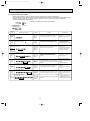
9-5. Trouble criterion of main parts
MSZ-FA25VA MSZ-FA35VA
Part name
Room temperature
thermistor(RT11)
Indoor coil thermistor
(RT12(MAIN), RT13(SUB))
Indoor fan motor(MF)
Horizontal vane
motor(MV1)
Vertical vane
motor(MV2)
i-see Sensor
motor(MT)
Front panel
driving motor
(MP)
Check method and criterion
Figure
Measure the resistance with a tester.
Refer to 9-7. "Test point diagram and voltage", "Indoor electronic control P.C.
board", the chart of thermistor.
Check 9-6. A.
RED
Measure the resistance between the terminals with a tester.
(Part temperature 10°C ~ 30°C)
Color of the lead wire
BRN-other one
ROTOR
YLW
BRN
Normal
235 " ~ 255 "
ORN
RED
Measure the resistance between the terminals with a tester.
(Part temperature 10°C ~ 30°C)
Color of the lead wire
BRN-other one
ROTOR
YLW
BRN
Normal
282 " ~ 306 "
ORN
ROTOR
YLW
BRN
Normal
94 " ~ 102 "
ORN
Turn the power ON(i-see Sensor is energized) with the aluminum block part
on the i-see Sensor P.C. board (upper part of i-see Sensor) covered with black
vinyl tape, then measure the voltage between connector terminals of i-see
Sensor using tester.
(Part temperature 10 ~ 40°C)
Aluminum block
i-see Sensor
w The aluminum block
part is covered with
black vinyl tape.
i-see Sensor(RR)
Connector
i-see Sensor P.C. board
i-see Sensor
Normal range
connector terminals
1.874 ~ 3.387V DC
2(-) - 4(+)
1.010 ~ 1.420V DC
1(+) - 2(-)
NOTE: Pay attention to static electricity.
PLASMA DEODORIZING/
PLASMA AIR PURIFYING
power
Check 9-6. F or G.
20
GRN
RED
Measure the resistance between the terminals with a tester.
(Part temperature 10°C ~ 30°C)
Color of the lead wire
BRN-other one
GRN
Black
vinyl tape
GRN
OB416_--1qxp
12/2/05 4:28 PM
Page 21
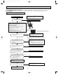
9-6. Troubleshooting flow
When POWER lamp flashes 3-time.
Indoor fan does not operate.
A Check of indoor fan motor
The indoor fan motor error has occurred, and the indoor fan doesn't operate.
Turn OFF the power supply.
Pay careful attention to the high voltage on
the fan motor connector CN211.
Is there any foreign matter that
interferes the rotation of the
line flow fan?
Turn ON the power supply, wait 5 seconds or more, and then press
EMERGENCY OPERATION switch.
Measure the supply voltage as follows within 12 seconds
after EMERGENCY OPERATION switch is pressed.
If more than 12 seconds passes by, turn OFF the power supply and
turn ON it again, then measure the voltage. w
1.Measure the voltage between CN211 1(+) and 3(-).
2.Measure the voltage between CN211 5(+) and 3(-).
No
Yes
wIf more than 12 seconds passes after EMERGENCY OPERATION switch
is pressed, the voltage mentioned above 2 goes 0V DC although the
indoor electric control P.C. board is normal.
Remove the foreign matter and
adjust the line flow fan.
Is there 325V DC between
CN211 1 (+) and 3 (-), and does
the voltage between CN211 5(+)
and 3(-) rise to the range of 3 to 6V
DC within 12 seconds after
EMERGENCY OPERATION switch
is pressed?
CN211
Yes
Replace the indoor fan motor.
Indoor electronic
control P.C. board
No
Replace the indoor electronic control P.C. board.
The indoor fan motor error has occurred, and the indoor fan repeats "12-second ON and 30-second OFF" 3 times, and then stops.
Measure the voltage between CN211
6(+) and 3(-) while the fan
motor is rotating.
Is it unchanged holding
0V DC or 15V DC?
No
(Changed)
Yes
(Unchanged)
Replace the indoor fan motor.
21
Replace the indoor electronic control P.C. board.
OB416_--1qxp
12/2/05 4:28 PM
Page 22
Indoor unit operates by pressing EMERGENCY OPERATION switch, but does not operate with the remote controller.
B Check of remote controller and receiver P.C. board
wCheck if the remote controller is exclusive for this air conditioner.
Switch ON the remote controller.
Is LCD display on the the remote
controller visible?
No
Replace the batteries. (Refer to 9-1.4.)
(not clear)
Yes
Remove the batteries, then set them back
and press RESET button. (Refer to 9-1.4.)
Check if the unit operates with the remote
controller.
Does the unit operate with the
remote controller?
No
Turn ON a radio to AM and press switch
ON the remote controller.
Yes
No
OK
Is noise heard from radio?
Replace the remote controller.
Yes
Are there any fluorescent lights of
inverter or rapid-start type within
the range of 1m?
No
Replace the indoor electronic
control P.C. board.
22
Yes
● Reinstall the unit away from lights.
● Attach a filter on receiving part.
OB416_--1qxp
12/2/05 4:28 PM
Page 23
The unit does not operate with the remote controller.
Also, POWER lamp does not light up by pressing EMERGENCY OPERATION switch.
C Check of indoor electronic control P.C. board and indoor fan motor
Turn OFF the power supply.
Remove indoor fan motor connector CN211, vane motor
connector CN151 front panel driving motor connector
CN1U1 and the i-see Sensor motor connector CN110
from the indoor electronic control P.C. board and turn
ON the power supply.
Measure the resistance of the front panel
driving motor coil.
Refer to 9-5.
Short/open circuit:
Replace the front panel driving motor
and the indoor electronic control P.C.
board.
Measure the resistance of the i-see Sensor
motor coil.
Refer to 9-5.
Short/open circuit:
Replace the i-see Sensor motor and the
indoor electronic control P.C. board.
Measure the resistance between CN211 3
and 4 of the indoor fan motor connector.
Short/open circuit:
Replace the indoor fan motor.
Measure the resistance of the horizontal vane
motor coil and the vertical vane motor coil.
Refer to 9-5.
Short/open circuit:
Replace the horizontal vane motor, the
vertical vane motor and the indoor
electronic control P.C. board.
Yes
Does the unit operate with the remote controller?
Does POWER lamp light up by pressing EMERGENCY
OPERATION switch?
No
Replace the varistor(NR11) and fuse(F11).
Yes
Are the varistor(NR11) burnt
and the fuse(F11) blown?
Turn OFF the power supply.
Check both “parts side” and “pattern
side” of the indoor electronic control P.C.
board visually.
No
Be sure to check both the fuse
and the varistor in any case.
Is the fuse(F11) blown only?
No
Yes
Measure the resistance between
1(+) and 3(-) of the indoor fan
motor connector (to CN211 on the
indoor electronic control P.C. board) .
w1,w2
Is the resistance 1M"
or more?
w1. The fan motor connector's 1 lead wire is red, whereas 3 is black.
w2. Connect "+" of the tester to fan motor connector's 1 lead
wire, and "-" to 3 lead wire, otherwise the resistance cannot be
measured properly.
No
Replace the fuse (F11) and the indoor fan motor.
Yes
Replace the fuse (F11).
Measure the resistance of cement
resistance R111 on the indoor electronic
control P.C. board.
Is the resistance
approx. 4"?
No
Yes
Indoor electronic
control P.C.Board
Replace the indoor electronic control P.C. board.
CN211
Varistor(NR11)
CN201
Fuse(F11)
23
Replace the indoor electronic control P.C. board
and the indoor fan motor.
OB416_--1qxp
12/2/05 4:28 PM
Page 24
• When unit cannot operate neither by the remote controller nor by EMERGENCY OPERATION switch.
Indoor unit does not operate.
• When POWER lamp flashes ON and OFF in every 0.5-second.
Outdoor unit does not operate.
D How to check mis-wiring and serial signal error
Turn OFF the power supply.
No
Is there rated voltage
in the power supply?
Check the power
supply.
Yes
Turn ON the power supply.
Is there rated voltage between
outdoor terminal block S1 and
S2?
No
Check the wiring.
Yes
Press EMERGENCY OPERATION switch once.
Does POWER lamp light up?
<Confirmation of the power to the indoor unit>
No
Yes
Is serial signal error indicated 6 minutes later?
No
Yes
Is there any mis-wiring,
poor contact, or wire
disconnection of the
indoor/outdoor
connecting wire?
Yes
Make them correct.
No
A
Turn OFF the power supply.
Check once more if the indoor/outdoor
B connecting wire is not mis-wiring.
Short-circuit outdoor terminal block S2 and
S3.
W1
Turn ON the power supply.
W1. Mis-wiring may damage indoor electronic control
P.C. board during the operation.
Be sure to confirm the wiring is correct before the
operation starts.
W3. Be sure to check this within 3 minutes after turning
ON. After 3 minutes, LED blinks 6 times. Even when
the inverter P.C.board or the outdoor electronic control
P.C.board is normal, LED blinks 6 times after
3 minutes.
(Except for outdoor unit of multi system type)
Does the LED on the inverter P.C. board
Replace the inverter P.C. board or
No
or the outdoor electronic control P.C.board
the outdoor electronic control P.C.board.
repeat "3.6-second-OFF and 0.8-second-ON
(Lighted or W2
quick blinking"? W3
not lighted)
W2 Be careful to the residual
voltage of smoothing capacitor.
Yes
A
· Turn OFF inverter-controlled lighting
equipment.
· Turn OFF the power supply and then
turn ON again.
· Press EMERGENCY OPERATION
switch.
Is serial signal
error indicated
6 minutes later?
Yes
B
· Reinstall
either the
unit or the
light each
No other away.
· Attach a filter
on remote
control
receiving
section of
the indoor
unit.
Turn OFF the power supply.
Remove the short-circuit between
outdoor terminal block S2 and S3.
Turn ON the power supply.
Is there amplitude of 10 to 20V DC
between outdoor terminal block S2
and S3? <Confirmation of serial
signal>
No
Is there any error of the
indoor/outdoor connecting wire,
such as the damage of the wire,
intermediate connection, poor
contact to the terminal block?
Yes Replace the
indoor/outdoor
connecting wire.
No
Yes
Is there rated voltage between indoor
terminal block S1 and S2?
<Confirmation of power voltage>
No
Is there any error of the
indoor/outdoor connecting wire,
such as the damage of the wire,
intermediate connection, poor
contact to the terminal block?
Yes
No
Replace the indoor electronic control P.C. board.
Be sure to release the failure-mode
recall function after checking.
Refer to outdoor unit service manual.
24
Yes Replace the
indoor/outdoor
connecting wire.
OB416_--1qxp
12/2/05 4:28 PM
Page 25
When All lamps flash ON and OFF every 0.5-second.
Indoor unit and outdoor unit do not operate.
E Check of installation of the horizontal vane
Turn OFF the
power supply.
Is the stopper of the horizontal vane
locked to the indoor unit correctly?
No
Relock the stopper of the
horizontal vane to the indoor unit.
Refer to 9-1.5.
Yes
Turn ON the
power supply.
No
Are all lamps flashing?
Yes
To check the continuity of the interlock switch
(Fan), measure the resistance of connector 1 - 2
connected to CN1R1 on the indoor
electronic control P.C. board.
Is there resistance 0 "?
No(∞)
Turn OFF the
power supply.
Replace the
interlock switch(Fan).
Yes
Replace the
indoor electronic
control P.C. board.
25
OK
OB416_--1qxp
12/2/05 4:28 PM
Page 26
When PLASMA/WASH lamp flashes 2-time.
When POWER lamp flashes 1 to 5 times while PLASMA DEODORIZING / PLASMA AIR PURIFYING power failure
mode is recalled.
F Check of PLASMA DEODORIZING power
After performing the check, make sure to release the failure mode recall function.
High voltage (approx. -3.9kV) is generated during PLASMA
DEODORIZING power operation.
Pay careful attention and never touch PLASMA unit and the
high-voltage lead part (red wire).
Turn ON the power supply.
Does PLASMA/WASH lamp
flash 2-time with unit stopping?
Yes
Replace the indoor electronic control P.C. board.
No
Make sure that the front panel is firmly closed. (Refer to 9-1.6
Figure 5)
1 While pressing both OPERATION SELECT
button and TOO COOL button on the remote controller at the
same time, press RESET button.
2 First, release RESET button.
And release the other two buttons after all LCD except the set
temperature in operation display section of the remote
controller is displayed after 3 seconds.
3 Press OPERATE/STOP (ON/OFF) button (the set temperature
is displayed)
4 And press PLASMA button once with the remote controller
headed towards the indoor unit. w1
PLASMA DEODORIZING operation is selected.
wThe plasma power operation check mode is set.(Refer to 9-2.5.)
Does PLASMA/WASH lamp stay OFF, or
continuously blink?
w1 Regardless of normal or abnormal, a short
beep is emitted once as the signal is received.
PLASMA DEODORIZING power supply is normal.
Working of SAFETY DEVICE (PLASMA UNIT)
due to uncomplete close of the front panel could
cause 2-time flash.
OFF
w2 Turn PLASMA DEODORIZING power OFF and ON again.
(For turning OFF PLASMA DEODORIZING power, refer to 9-2.3.)
(If it goes normal without turning OFF and ON, PLASMA/WASH lamp
doesn't go OFF.)
Continuously blinking.
Remove PLASMA DEODORIZING filter,
firmly close the front panel, and then perform
PLASMA DEODORIZING power operation
check (w2).
Does PLASMA/WASH lamp stay OFF, or
continuously blink?
PLASMA
DEODORIZING
operation
Abnormal discharge may occur due to much dirt on the
PLASMA unit, clean the unit.
After cleaning, make sure to attach the unit since it is
completely dry.
If PLASMA DEODORIZING power operation check is
performed with the plasma unit wet, protection gets active
and PLASMA/WASH lamp blinks continuously as well.
OFF
Continuously blinking.
Turn OFF the power supply, and check the
SAFETY DEVICE(PLASMA UNIT).
Is it firmly fixed?
No
Firmly fix the SAFETY DEVICE(PLASMA UNIT).
Yes
Work and Not-work the SAFETY DEVICE
(PLASMA UNIT) using something like a screw
driver, and measure the resistance between
CN1T2 1 and 3 on the indoor electronic
control P.C. board. Does the SAFETY
DEVICE function?
No
Replace the SAFETY DEVICE(PLASMA UNIT).
Yes
Keep the SAFETY DEVICE(PLASMA UNIT)
Not-work (close) using something like a screw
driver. Turn ON the power supply. Is the voltage
between CN1 1(+) and 2(GND)
on the PLASMA POWER P.C. board
(PLASMA DEODORIZING) 0V with the unit
stopping? (Refer to 9-7.)
No
9.5V DC is generated.
Replace the indoor electronic control P.C. board.
Yes
Set the plasma power failure mode recall function.
(Refer to 9-2.2)
When PLASMA DEODORIZING power turns
ON by pressing PLASMA button once, is there
12.5V DC between CN1 1(+) and 2(GND)?
Replace the indoor electronic control P.C. board,
after check of the wiring of CN1T1 on the indoor electronic
control P.C. board.
No
Yes
Replace the PLASMA POWER P.C. board
(PLASMA DEODORIZING).
26
OB416_--1qxp
12/2/05 4:28 PM
Page 27
When PLASMA/WASH lamp flashes 2-time.
When POWER lamp flashes 1 to 5 times while PLASMA DEODORIZING / PLASMA AIR PURIFYING power failure
mode is recalled.
G Check of PLASMA AIR PURIFYING power
After performing the check, make sure to release the failure mode recall function.
High voltage (approx. -3.9kV) is generated during PLASMA
AIR PURIFYING power operation.
Pay careful attention and never touch PLASMA unit and the
high-voltage lead part (red wire).
Turn ON the power supply.
Does PLASMA/WASH lamp
flash 2-time with unit stopping?
Yes
Replace the indoor electronic control P.C. board.
No
Make sure that the front panel is firmly closed. (Refer to 9-1.6
Figure 5)
1 While pressing both OPERATION SELECT
button and TOO COOL button on the remote controller at the
same time, press RESET button.
2 First, release RESET button.
And release the other two buttons after all LCD except the set
temperature in operation display section of the remote
controller is displayed after 3 seconds.
3 Press OPERATE/STOP (ON/OFF) button (the set temperature
is displayed)
4 And press PLASMA button twice with the remote controller
headed towards the indoor unit. w1
PLASMA AIR PURIFYING operation is selected.
wThe plasma power operation check mode is set.(Refer to 9-2.5.)
Does PLASMA/WASH lamp stay OFF, or
continuously blink?
w1 Regardless of normal or abnormal, a short
beep is emitted once as the signal is received.
PLASMA AIR PURIFYING power supply is normal.
Working of SAFETY DEVICE (PLASMA UNIT)
due to uncomplete close of the front panel could
cause 2-time flash.
OFF
w2 Turn PLASMA AIR PURIFYING power OFF and ON again.
(For turning OFF PLASMA AIR PURIFYING power, refer to 9-2.3.)
(If it goes normal without turning OFF and ON, PLASMA/WASH lamp
doesn't go OFF.)
Continuously blinking.
Remove PLASMA AIR PURIFYING filter,
firmly close the front panel, and then perform
PLASMA AIR PURIFYING power operation
check (w2).
Does PLASMA/WASH lamp stay OFF, or
continuously blink?
PLASMA
AIR PURIFYING
operation
Abnormal discharge may occur due to much dirt on
the PLASMA unit, clean the unit.
After cleaning, make sure to attach the unit since it is
completely dry.
If PLASMA AIR PURIFYING power operation check is
performed with the plasma unit wet, protection gets active
and PLASMA/WASH lamp blinks continuously as well.
OFF
Continuously blinking.
Turn OFF the power supply, and check the
SAFETY DEVICE(PLASMA UNIT).
Is it firmly fixed?
No
Firmly fix the SAFETY DEVICE(PLASMA UNIT).
Yes
Work and Not-work the SAFETY DEVICE
(PLASMA UNIT) using something like a screw
driver, and measure the resistance between
CN1T2 1 and 3 on the indoor electronic
control P.C. board. Does the SAFETY
DEVICE function?
No
Replace the SAFETY DEVICE(PLASMA UNIT).
Yes
Keep the SAFETY DEVICE(PLASMA UNIT)
Not-work (close) using something like a screw
driver. Turn ON the power supply. Is the voltage
between CN1 1(+) and 2(GND)
on the PLASMA POWER P.C. board
(PLASMA AIR PURIFYING) 0V with the unit
stopping? (Refer to 9-7.)
No
9.5V DC is generated.
Replace the indoor electronic control P.C. board.
Yes
Set the plasma power failure mode recall function.
(Refer to 9-2.2)
When PLASMA AIR PURIFYING power turns
ON by pressing PLASMA button twice, is there
12.5V DC between CN11(+) and 2(GND)?
Replace the indoor electronic control P.C. board,
after check of the wiring of CN1T1 on the indoor electronic
control P.C. board.
No
Yes
Replace the PLASMA POWER P.C. board
(PLASMA AIR PURIFYING).
27
OB416_--1qxp
12/2/05 4:28 PM
Page 28
Indoor unit and outdoor unit do not operate.
H Check of auto front panel
Turn the remote controller ON.
No
Does the front panel automatically
open? (Does it start to move?)
Yes
Is the connectors for the front panel
driving motor unit connected?
(Motor side or P.C. board side)
No
Connect the connector and
check from the start again.
Yes
Is the resistance between terminals
of the front panel driving motor unit
normal?
(Refer to 9-5.)
Yes
Is the front panel held 10mm or
more upper than the level line of
the nozzle top?
Yes
Replace the indoor electric
control P.C. board.
No
Replace the front panel
driving motor unit.
Front panel is normal.
10 mm or
more
Z-Z side view
28
No
Replace the front panel
driving motor unit.
OB416_--1qxp
12/2/05 4:28 PM
Page 29
I Electromagnetic noise enters into TV sets or radios
No
Is the unit earthed?
Earth the unit.
Yes
Is the distance between the
antennas and the indoor
unit within 3m, or is the
distance between the
antennas and the outdoor
unit within 3m?
Yes
Extend the distance between
the antennas and the indoor
unit, and/or the antennas and
the outdoor unit.
No
Is the distance between the
TV sets or radios and the
indoor unit within 1m, or is
the distance between the TV
sets or radios and the
outdoor unit within 3m?
Yes
Extend the distance between
the TV sets and/or radios and
the indoor unit, or the TV sets
or radios and the outdoor unit.
No
Are the antennas damaged?
Is the coaxial cable damaged?
Is there any poor contact in
the antenna wiring?
Yes
Replace or repair the antenna.
Replace or repair the coaxial cable.
No
Is the indoor/outdoor
connecting wire of the air
conditioner and the wiring of
the antennas close?
Yes
Extend the distance between
the indoor/outdoor connecting
wire of the air conditioner and
the wiring of the antennas.
No
Even if all of the above conditions is fulfilled, the electromagnetic noise may enter, depending on
the electric field strength or the installation condition (combination of specific conditions such as
antennas or wiring).
Check the followings before asking for service.
1.Devices affected by the electromagnetic noise
TV sets, radios (FM/AM broadcast, shortwave)
2.Channel, frequency, broadcast station affected by the electromagnetic noise
3.Channel, frequency, broadcast station unaffected by the electromagnetic noise
4.Layout of ;
indoor/outdoor unit of the air conditioner, indoor/outdoor wiring, grounding wire, antennas, wiring
from antennas, receiver
5.Electric field intensity of the broadcast station affected by the electromagnetic noise
6.Presence or absence of amplifier such as booster
7.Operation condition of air conditioner when the electromagnetic noise enters in.
1)Turn OFF the power supply once, and then turn ON the power supply. In this situation check for
the electromagnetic noise.
2)Within 3 minutes after turning ON the power supply, press OPERATE/STOP (ON/OFF) button
on the remote controller for power ON, and check for the electromagnetic noise.
3)After a short time (3 minutes later after turning ON), the outdoor unit starts running. During
operation, check for the electromagnetic noise.
4)Press OPERATE/STOP (ON/OFF) button on the remote controller for power OFF, when the
outdoor unit stops but the indoor/outdoor communication still runs on. In this situation check for
the electromagnetic noise.
After checking the above, consult the service representative.
29
OB416_--1qxp
12/2/05 4:28 PM
Page 30
9-7. Test point diagram and voltage
MSZ-FA25VA
MSZ-FA35VA
Indoor electronic control P.C. board
5V DC
12V DC
Cement resistance
(R111)
Indoor fan motor
(CN211)
1325V DC
3(-) Fiducial terminal of
cathode side on measuring high-voltage DC
415V DC
5(+)3-6V DC
6(+)0V DC or 15V DC
Power supply input
230V AC
Interlock switch(Fan)
(CN1R1)
{
Room temperature
thermistor (CN111)
Varistor
(NR11)
SW P.C. Board
WASH reset
switch(SW2)
CN2011
(Used for check of conducting of thermal fuse)
Indoor coil thermistor
RT12(MAIN)12
RT13(SUB)34
(CN112)
Plasma deodorizing/air
purifying filter units
(CN1T1)
Emergency
operation
switch(SW1)
Safety device(Plasma unit)
(CN1T2)
Horizontal and
Vertical vane
motor(CN151)
Power monitor
receiver P.C.
board.
}
i-see Sensor
(CN110)
Release of Auto restart
function
Solder the Jumper wire
to JR07.
(Refer to 8-3.)
Fuse
(F11)
Front panel
driving motor
(CN1U1)
Indoor coil thermistor [RT12 (MAIN), RT13 (SUB)]
Room temperature thermistor (RT11)
High-voltage lead wire
(Red)
3DC 2.5V during PLASMA
AIR PURIFYING/PLASMA
DEODORIZING operation
2GND
1DC 12.5V during PLASMA
AIR PURIFYING/PLASMA
DEODORIZING operation
Resistance (k")
Plasma power P.C. board
CN1
Standard lead wire
(Green)
Temperature (:)
30
Timer short mode
point JPG, JPS
(Refer to 8-1.)
OB416_--2qxp
12/2/05 4:26 PM
10
Page 31
DISASSEMBLY INSTRUCTIONS
<"Terminal with locking mechanism" Detaching points>
The terminal which has the locking mechanism can be detached as shown below.
There are two types ( Refer to (1) and (2)) of the terminal with locking mechanism.
The terminal without locking mechanism can be detached by pulling it out.
Check the shape of the terminal before detaching.
(1) Slide the sleeve and check if there is a locking lever or not.
(2) The terminal with this connector has the
locking mechanism.
Sleeve
Locking lever
1Slide the sleeve.
2Pull the terminal while
pushing the locking
lever.
1Hold the sleeve, and
pull out the terminal
slowly.
Connector
MSZ-FA25VA MSZ-FA35VA
INDOOR UNIT
PHOTOS
OPERATING PROCEDURE
1. Removing the panel
Photo 1
(1) Press and unlock the knobs on both sides of the front
panel and lift the front panel until it is level, and then pull
the hinges forward to remove the front panel.
(2) Remove the horizontal vane.
(3) Remove the screw caps of the panel.
Remove the screws. (See Photo 1.)
(4) Remove the screw of the front panel driving motor.
(See Photo 2.)
(5) Hold the lower part of both ends on the panel and pull it
slightly toward you, and then remove the panel by pushing
it upward.
Front panel
Screws of the panel
Horizontal vane
Photo 2
Screw of the front panel
driving motor
31
OB416_--2qxp
12/2/05 4:26 PM
Page 32
OPERATING PROCEDURE
PHOTOS
2. Removing the electronic control P.C. board, the
power monitor receiver P.C. board, i-see Sensor,
SW P.C. board and the terminal block
(1) Remove the horizontal vane, the panel (Refer to 1.) and
the corner box.
(2) Remove the screw of the V.A. clamp, and then the
indoor/outdoor connecting wire.(See Photo 3.)
(3) Remove the switch holder from the electrical cover.
(See Photo 4.)
(4) Remove the screw of the electrical cover, and then the
electrical cover. (See Photo 4.)
(5) Remove the ground wire connected to the indoor electronic
control P.C. board from the electrical box. (See Photo 5.)
(6) Unhook the power monitor receiver P.C. board holder from
the catch. (See Photo 5.)
(7) Open the rear cover of the power monitor receiver P.C.
board holder and pull out the power monitor receiver P.C.
board.
(8) Remove the screws of the i-see Sensor cover and the i-see
Sensor motor, and then remove the i-see Sensor motor.
(9) Open the i-see Sensor holder and pull out the i-see Sensor.
(10) Open the switch holder and pull out SW P.C. board.
(11) Pull the electronic control P.C. board slightly toward you
from the electrical box, and disconnect TAB3 and all the
connectors on the electronic control P.C. board.
(LD101 and LD105 are direct-mounted to the electronic
control P.C. board.)
(12) Pull out the electronic control P.C. board from the electrical
box.
(13) Remove the ground wire connected to the heat exchanger
from the electrical box. (See Photo 5.)
(14) Unhook the catches of the electrical box, and pull out the
electrical box.
(15) Remove the screws of the terminal block cover, and then
the terminal block cover and the terminal block holder.
(See Photo 3.)
(16) Remove the terminal block by sliding it.
Photo 3
Screws of
the terminal
block cover
Drain hose
Screw of the V.A. clamp
Photo 4
Switch holder
Screw of the
electrical cover.
Photo 5
Ground wires
Fan motor
connector (CN211)
Connector of the
interlock switch(Fan)
(CN1R1)
3. Removing the electrical box
(1) Remove the horizontal vane, the panel (Refer to 1.) and the
corner box.
(2) Remove the screw of the V.A. clamp, and then the indoor/
outdoor connecting wire.(See Photo 3.)
(3) Remove the switch holder and the electrical cover.
(See Photo 4.)
(4) Remove the ground wire connected to the heat exchanger
from the electrical box.(See Photo 5.)
(5) Disconnect the following connectors on the electronic
control P.C. board; the fan motor connector <CN211>, the
indoor coil thermistor connector <CN112>, the vane motor
connector <CN151>, the connector of the interlock switch
(Fan) of the horizontal vane <CN1R1>, the connector of
the safety device (plasma unit) <CN1T2>, the connector of
the plasma power P.C. board <CN1T1>, the connector of
the front panel driving motor <CN1U1>.
(6) Unhook the catches of the electrical box, and pull out the
electrical box. (See Photo3.)
32
Indoor coil thermistor
connector (CN112)
Connector of the
plasma power
P.C.board(CN1T1)
Connector of the
safety device(Plasma
unit) (CN1T2)
Vane motor
connector (CN151)
Power monitor
i-see Sensor
receiver P.C.
board holder
Connector of the
front panel driving
motor (CN1U1)
i-see Sensor
cover
OB416_--2qxp
12/2/05 4:26 PM
Page 33
OPERATING PROCEDURE
PHOTOS
Photo 6
4. Removing the horizontal vane motor unit
(1) Remove the horizontal vane and the panel. (Refer to 1.)
(2) Remove the screws of the horizontal vane motor unit,
and pull out the horizontal vane motor unit. (See Photo 6.)
(3) Disconnect the connector from the horizontal vane motor
unit.
Screw of the horizontal
vane motor unit
Photo 7
5. Removing the vertical vane motor unit
(1) Remove the horizontal vane, the panel (Refer to 1.) and
the corner box.
(2) Pull out the drain hose from the nozzle assembly, and
remove the nozzle assembly. (See Photo 5.)
(3) Remove the crank of the vertical vane motor unit from the
arm of the vertical vane.(See Photo 7.)
(4) Remove the screws of the vertical vane motor unit, and pull
the vertical vane motor unit. (See Photo 7.)
Arm
Crank of the vertical
vane motor unit
Screws of the vertical
vane motor unit
6. Removing the indoor fan motor and the line flow
fan
(1) Remove the horizontal vane, the panel (Refer to 1.) and
the corner box.
(2) Remove the switch holder and the electrical box. (Refer to 3.)
(3) Pull out the drain hose from the nozzle assembly, and
remove the nozzle assembly.
(4) Remove the screws fixing the motor bed. (See Photo 8.)
(5) Loosen the screw fixing the line flow fan. (See Photo 9.)
(6) Remove the motor bed together with fan motor and motor
band.
(7) Release the hooks of the motor band, and remove the
motor band then pull out the indoor fan motor.
(8) Remove the screws fixing the left side of the heat
exchanger. (See Photo 10.)
(9) Lift the heat exchanger, and pull out the line flow fan to the
lower-left.
Photo 8
Screws of
the motor
bed
Photo 10
Photo 9
Screws of the
left side of the
heat exchanger
Screw of
the line
flow fan
33
Motor band
OB416_--2qxp
12/2/05 4:26 PM
Page 34
OPERATING PROCEDURE
PHOTOS
7. Removing the plasma power P.C. board
Photo 11
(1) Remove the horizontal vane, the panel (Refer to 1.) and
the corner box.
(2) Remove the switch holder and the electrical cover.
(Refer to 3.)
(3) Disconnect the connector of the front panel driving motor
<CN1U1> from the electronic control P.C. board.
(4) Remove the front panel driving motor.
(5) Remove the screw of the plasma element holder, and remove
the plasma element holder from the heat exchanger.
(See Photo 11.)
(6) Unhook all the catches of plasma unit cover and remove
the plasma unit cover. (See Photo 12.)
(7) Remove the terminals with locking mechanism connected
to the plasma power P.C. board and the safety device
(Plasma unit). (See Photo 13.)
(8) Remove the plasma electrical box from the plasma element
holder.
(9) Remove the screw fixing the plasma electrical box, and
open the plasma electrical box then pull out the plasma
power P.C. board from the plasma electrical box.
(See Photo 13.)
Screw of the plasma
element holder
Front panel
driving motor
Photo 12
Plasma unit cover
Photo 13
Screw of
Terminal the plasma
electrical box
Terminal
Safety device
(Plasma unit)
Terminal Plasma
Terminal
power
P.C. board
34
OB416_--2qxp
12/2/05 4:26 PM
11
Page 35
PARTS LIST
MSZ-FA25VA
MSZ-FA35VA
11-1. INDOOR UNIT STRUCTURAL PARTS
1
11-2. ACCESSORY AND REMOTE
CONTROLLER
10
9
8
7
2
3
4
5
6
11-1. INDOOR UNIT STRUCTURAL PARTS
No.
1
2
3
4
5
6
7
8
Part No.
E02
E02
E02
E02
E02
E02
E02
E02
E02
E02
897
A32
913
913
913
914
913
913
A32
913
234
234
000
067
010
100
100
975
975
970
Part name
Q'ty/unit
Symbol
in Wiring MSZ-FA25VA - MSZ-FA35VA Diagram
A1
A2
A1
A2
1
1
BOX
BOX
PANEL ASSEMBLY
SCREW CAP
FRONT PANEL
AIR FILTER (LEFT)
AIR FILTER (RIGHT)
CORNER BOX (RIGHT)
CORNER BOX (RIGHT)
INSTALLATION PLATE
1
2
1
1
1
1
Remarks
1
1
1
1
1
1
1
2
1
1
1
1
1
1
1
1
1
1
1
1
1
1
1
1
1
1
1
1
1
1
1
1
Including No.3,4
2PCS/SET
11-2. ACCESSORY AND REMOTE CONTROLLER
9
10
E02 913 426 REMOTE CONTROLLER
E02 527 083 REMOTE CONTROLLER HOLDER
35
KM05A
OB416_--2qxp
12/2/05 4:26 PM
Page 36
MSZ-FA25VA
MSZ-FA35VA
11-3. INDOOR UNIT ELECTRICAL PARTS
AND FUNCTIONAL PARTS
29
30
27
25
26
24
20
1
28
31
2
22
3
4
32
5
6
7
21
23
8
18
17
16
15
18
14
13
11
12
9
11-4. INDOOR UNIT HEAT EXCHANGER
33
34
35
36
10
18
19
OB416_--2qxp
12/2/05 4:26 PM
Page 37
11-3. INDOOR UNIT ELECTRICAL PARTS AND FUNCTIONAL PARTS
No.
Part No.
Part name
Q'ty/unit
Symbol
in Wiring MSZ-FA25VA- MSZ-FA35VADiagram
A1
A2
A1
A2
1
1
E02 751 509 BEARING MOUNT
1
1
E02 001 504 SLEEVE BEARING
1
1
E02 897 702 DRAIN HOSE
1
1
E02 913 235 NOZZLE ASSEMBLY
1
1
E02 897 303 VANE MOTOR UNIT (HORIZONTAL) MV1
1
1
E02 897 316 INTERLOCK SWITCH(FAN)
MV2
1
1
E02 913 303 VANE MOTOR UNIT (VERTICAL)
1
1
E02 913 040 HORIZONTAL VANE
F11
1
1
E02 A49 382 FUSE
NR11
1
1
E02 661 385 VARISTOR
1
1
E02 913 095 POWER MONITOR RECEIVER P.C. BOARD HOLDER
RR
1
1
E02 913 391 i-see Sensor
MT
1
1
E02 914 303 i-see Sensor MOTOR
1
1
E02 897 784 VA CLAMP
1
1
E02 897 780 TERMINAL BLOCK COVER
1
1
E02 897 779 TERMINAL BLOCK HOLDER
TB
1
1
E02 913 375 TERMINAL BLOCK
1
1
E02 913 452 ELECTRONIC CONTROL P.C. BOARD W1
18
E02 914 452 ELECTRONIC CONTROL P.C. BOARD W1
19 E02 897 308 ROOM TEMPERATURE THERMISTOR RT11
1
1
RT12, RT13
1
1
E02 913 307 INDOOR COIL THERMISTOR
20
RT12, RT13
E02 914 307 INDOOR COIL THERMISTOR
21 E02 913 782 SWITCH HOLDER
1
1
MF
22 E02 897 300 INDOOR FAN MOTOR W2
1
1
23 E02 897 333 MOTOR BAND
1
1
MP
24 E02 898 303 FRONT PANEL DRIVING MOTOR
1
1
25 E02 897 302 LINE FLOW FAN
1
1
26 E02 913 775 PLASMA ELEMENT HOLDER
1
1
27 E02 913 776 PLASMA UNIT COVER
1
1
28 E02 913 777 PLASMA ELECTRICAL BOX
1
1
29 E02 897 440 PLASMA POWER P.C. BOARD
2
2
30 E02 898 316 SAFETY DEVICE (PLASMA UNIT)
1
1
31 E02 913 774 PLASMA AIR PURIFYING FILTER UNIT PLASMA_A
1
1
32 E02 914 774 PLASMA DEODORIZING FILTER UNIT PLASMA_D
1
1
W1 Including SW P.C. BOARD and POWER MONITOR RECEIVER P.C. BOARD
W2 Including FAN MOTOR RUBBER MOUNT (2 PCS/SET)
1
2
3
4
5
6
7
8
9
10
11
12
13
14
15
16
17
1
1
1
1
1
1
1
1
1
1
1
1
1
1
1
1
1
1
1
1
1
1
1
1
1
1
1
1
1
1
1
1
1
1
1
1
1
1
1
1
1
1
1
1
1
1
1
2
1
1
1
1
1
1
1
1
1
1
1
1
2
1
1
1
1
1
1
1
1
1
Remarks
UP & DOWN
RIGHT & LEFT
3.15A
AUTO RESTART
AUTO RESTART
RC0J40-
11-4. INDOOR UNIT HEAT EXCHANGER
33
34
35
E02
E02
E02
E02
913
914
815
151
620
620
666
667
INDOOR HEAT EXCHANGER
INDOOR HEAT EXCHANGER
UNION (GAS)
UNION (LIQUID)
37
1
1
1
1
1
1
{9.52
{6.35
or RC0J30-
OB416_--2qxp
12
12/2/05 4:26 PM
Page 38
OPTIONAL PARTS
12-1. DEODORIZING CERAMIC FILTER
Replacement of the deodorizing ceramic filter(about once every 6 years)
Deodorizing ceramic filter is installed inside PLASMA DEODORIZING filter unit. The filter is fragile. Handle it with care.
NOTE: PLASMA DEODORIZING filter unit may not operate properly if the deodorizing ceramic filter is not installed.
Be sure to install the deodorizing ceramic filter.
(1) Release the two knobs to open the filter unit.
(2) Pull the side knobs to outward and then
forward to remove, as illustrated below.
(3) Pull out the deodorizing ceramic filter from the side of
the filter unit.
Deodorizing ceramic filter
(1)
(2)
(4) Install the deodorizing ceramic filter by following the
removal procedure in reverse.
Model
Part No.
MSZ-FA25VA
MSZ-FA35VA
MAC-305FT-E
12-2. QUICK CLEAN KIT
● You can sweep the surface of heat exchanger if you install the special-made brush to your vacuum cleaner.
Model
Part No.
MSZ-FA25VA
MSZ-FA35VA
MAC-093SS-E
Heat exchanger
38
OB416_--2qxp
12/2/05 4:26 PM
Page 39
39
OB416_--2qxp
12/2/05 4:26 PM
Page 40
HEAD OFFICE: TOKYO BLDG., 2-7-3, MARUNOUCHI, CHIYODA-KU, TOKYO100-8310, JAPAN
C Copyright 2005 MITSUBISHI ELECTRIC ENGINEERING CO.,LTD
Distributed in Jan. 2006. No. OB416 REVISED EDITION-A 6
Distributed in Jul. 2005. No. OB416 6
Made in Japan
New publication, effective Jan. 2006
Specifications subject to change without notice.