1
_)
_
_-'
_
_F_ "
IINPORTANT NANUAL
Db Not Throw Away
Operator's
Manual
Model No.
358.798490
Always Wear Eye Protection
®
HOURS (CST)
Men -Sat 7am.-7pm
Sun- 10 a,rn -7pm
32 cc/2.0 cu. in. 2-CYCLE
17 Inch Semi-Automatic Head
GAS WEEDWACKER®
WARNING:
READ THE OPERATOR'S
MANUAL AND FOLLOW
ALL WARNINGS AND
SAFETY INSTRUCTIONS.
FAILURE 3"0 DO SO CAN
RESULT IN SERIOUS
INJURY.
o Assembly
- Operation
- Customer Responsibilities
o Service and Adjustments
° Repair Parts
Sears, Roebuck and Co., Hoffman Estates, 1L60179 U.S.A.
530-083614-1-03/08/95
SAFETY RULES
TACT
sPA.K
.LUG
ToP.sv NT
ACCID
STA.
AL .G
WHeN
SEI"..
I
cAu
oN:
ALWAYS
D,SCONNECT
SPA.K
F'LUG
Wi.
WiR
WH RE
rrCANNOT
CO.-I
ADJUSTING OR MAKING REPAIRS.
.....................
j
OPERATOR
SAFETY
o Do not smoke or allow smoking near fuel or the unit or
while using the uniL
- Wipe up all fuel spills before starting engine,
o Always wear' safety eye protection
o Always wear long pants, long sleeves, boots and
_loves_ Wearing safety leg guards is recommended.
o not go barefoot or wear sandals, short pants, short
sleeves, Being fully covered helps to protect you from
pieces of toxic plants thrown by the cutting head_
. Secure hair so it is above shoulder length Secure
loose clothing, jewelry, or clothing with loosely han_ing !ies, straps, tassels, etc.; they can be caught m
moving parts
. Do not operate this unit when you are tired, ill, or
under the influence of alcohol, drugs, or medication
• Wear hearing protection if you use this unit for more
than 1-1/2 hours per day
- Never start or run the engine inside a closed room or
building Breathing exhaust fumes can kin
. Keep handles free of oil and fuel
- !f situations occur which are not covered in this
manual, use care and good judgement
UNIT/MAINTENANCE
o Move at least 10 feet (3 meters) away from fueling sits
before starting engine.
° Stop engine and allow unit to cool before removing
fuel cap
CUTTING SAFETY
o Inspect the area to be cut before each use. Remove
objects (rocks, broken glass, nails, wire, string, etc.)
which can be thrown or become entangled in the
semi-automatic line head
.
Keep others including children, animate, bystanders
and helpers at least 50 feet (15 meters) away. Stop
the engine immediately il you are approached,
° Always keep the engine on the right-hand side of your
body
o Hold the unit firmly with both hands
° Keep firm footing and balance Do not over-reach
o Keep the semi-automatic line head below waist level
SAFETY
o Look for and replace damaged or toose parts before
each use Look for and repair fuel leaks before use
Keep the unit in good working condition
* Use only ,080" diameter monofilarnent line Never use
wire, rope, string, etc
. Keep the cutting line at the proper length
. Make sure the unit is maintained and assembled correctly as listed in this manual
- Install the required shield properly before using the
unit
o Do not raise the engine above your waist
° Keep all parts of your body away from semi-automatic
Iine head and muffler when engine is running
° Cut from your right to your left
o Use only for jobs explained in this manual.
TRANSPORTING
AND STORAGE
FUEL SAFETY
o Stop the unit before transporting
• Allow the engine to cool, and secure the unit before
storing or transporting in a vehicle
° Empty the fuel tank before storing or transporting the
unit Use up any fuel left in the carburetor by starting
the engine and letting the engine run until it stops,,
• Store unit and fuel in an area where fuel vapors cannot reach sparks or open flames from water heaters,
electric motors or switches, furnaces, etc
°
.
°
o Store unit so the line limiter cannot accidentaIly cause
injury
• Store the unit out of the reach of children
.
.
Use only the specified semi-automatic trimmer head.
Make carburetor adjustments with the lower end supported to prevent the trimmer line from contacting any
object Hold unit by hand
o Keep others away when making carburetor adjustments
°
Use only good quality SEARS accessories as recommended for this unit.
Mix and pour fuel outdoors
Keep away from sparks or flames
Use a container approved for fuel
SAFETY NOTICE
Exposure to vibrations through prolonged use of gasotine powered hand units could cause blood vessel or nerve damage in the
fingers, hands, and joints of people prone to circulationdisorders or abnormal swellings Prolonged use in cold weather has been
linked to blood vesset damage in otherwise healthy people If symptoms occur such as numbness, pain, toss of strength, change
in skin color or texture, or toss of feeling in the fingers, hands or joints discontinue the use of this unit and seek medical attention An antiwibration system does not guarantee the avoidance o! these problems Users who operate power tools on a continual and regular basis must monitor closely their physica{ condition and the condition of this unit.
LOOK
FOR --THIS
SYMBOL TO
POINT OUT
IMPORTANT
SAFETY ISPRECAUTIONS.
IT MEANS
A'I'rENTION!!!
BECOME
ALERT!!!
YOUR SAFETY
iNVOLVED.
-2-
SAFETY RULES
DANGER
THIS POWER UNIT CAN BE DANGEROUS! THIS UNIT CAN CAUSE SERIOUS INJURY OR
BLINDNESS TO THE OPERATOR AND OTHERS. THE WARNINGS AND SAFETY INSTRUCTIONS IN
THIS MANUAL MUST BE FOLLOWED TO PROVIDE REASONABLE SAFETY AND EFFICIENCY IN
USING THIS UNIT THE OPERATOR IS RESPONSIBLE FOR FOLLOWING THE WARNINGS AND
INSTRUCTIONS IN THIS MANUAL AND ON THE UNIT_ READ THE ENTIRE OPERATOR'S MANUAL
BEFORE ASSEMBLING AND USING THE UNIT/RESTRICT
THE USE OF THIS POWER UNIT TO
PERSONS WHO READ, UNDERSTAND AND FOLLOW THE WARNINGS AND INSTRUCTIONS IN
THIS MANUAL AND ON THE UNFI_.NEVER ALLOW CHILDREN TO USE THIS TOOL.
THIS UNIT IS DESIGNED FOR LINE
TRIMMER USE ONLY. NEVER USE ANY
OTHER CUTTING ATTACHMENT WITH
THIS UNIT. BLADES AND HEADS WITH
FLAILING DEVICES CAN CAUSE SERIOUS
INJURY
TRIMMER LINE CAN THROW OBJECTS
WARNING
VIOLENTLY.
YOU CAN BE BLINDED
OR INJURED. WEAR EYE AND LEG
PROTECTION.
PROTECTION
HAZARD ZONE FOR THROWN OBJECTS°
TRIMMER LINE CAN THROW OBJECTS
VIOLENTLY. OTHERS CAN BE BLINDED
OR INJURED_ KEEP PEOPLE AND ANIMALS 50 FEET (15 METERS) AWAY.
HAZARD
ONZ_E
READ OPERATOR'S MANUAL. FOLLOW
ALL WARNINGS AND INSTRUCTIONS.
FAILURE TO DO SO CAN RESULT IN
SERIOUS INJURY_
OPERATOR'S
MANUAL
-3_
CONGRATULATIONS on your purchase of a Sears
Craftsman Gas Weedwacker, tt has been designed, engineered and manufactured to give you the best possible
dependability and performance.
Should you experience any problems you cannot easily
remedy, please contact your nearest Sears Service CentedDepartment, Sears has competent, well trained technicians and the proper tools to service or repair this unit
Please read and retain this manual The instructions will
enable you to assemble and maintain your unit properly.,
Always observe the "SAFETY RULES."
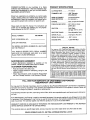
PRODUCT
SPECtRCATIONS
CUTTING PATH .................17" (43cm)
TRIMMER LINE ....................
080" Diameter
Monofilament
SEMI-AUTOMATIC
Counterclockwise
HEAD ROTATION ................
(for operator) .
ENGINE ............................. 32cc, 2-cycle Air Cooled
FUEL/OIL MIX RATIO ...... 40:1 (3.2 ozooil per
gallon gas)
IGNITION .................................
Solid State
(air gap D10" to O14")
IGNITION TIMING ........... Non-adjustable, fixed
358.798490
MODEL NUMBER:
SPARK PLUG .....................Champion (RCJ-8Y)
SPARK PLUG GAP ............ 025" (.6ram)
DATE CODE/SERIAL NO.:
ENGINE RPM ....................7,500 RPM Max
DATE OF PURCHASE:
THE MODEL AND SERIAL NUMBER WILL BE FOUND
ON THE PRODUCT
YOU SHOULD RECORD BOTH SERIAL NUMBER
AND DATE OF PURCHASE AND KEEP IN A SAFE
PLACE FOR FUTURE REFERENCE.
MAINTENANCE
AGREEMENT
A Sears Maintenance Agreement is available on this
product. Contact your nearest Sears Store for details.
CUSTOMER
RESPONSIBILITIES
Read and observe the safety rules..
• Foliow a regular schedule in maintaining, caring for, and
using your uniL
• Follow the instructions under "Customer Responsibilities" and "Storage" sections of this Operator's Manual.
SPECIAL NOTICE
FoPuserson U.S. ForestLandand in somestates,including
California (Public ResourcesCodes 4442 and 4443), Idaho,
Maine, Minnesota,New Jersey, Oregon, arid Washington:
Certain internal combustionengines operated on forest
brush, andlor grass.-covered
landsin the above areas are
requiredto be equippedwith a spark arrestor,maintainedin
effectiveworkingorder,or the enginemust be constructed
equipped, and maintained for the preventionof fire. Check
withyour state or local authoritiesfor regulationspertaining
to these requirementsFailureto follow these requirements
is a violationof thetaw. Thisunit is not factory-equippedwith
a spark arrestor; however,a spark arrestor is availableas an
optional part, If a spark arrestor is required inyour area, contact your SEARS Service Center/Departmentfor thecorrect
kit.
_M_nu4ar.:l_red
ut_det or,e or m_e of lt_e followittg US pale_tts 5
5 348 68_, 5 343 83"_: 5 276 958:5 269 665 5 02(_223 4 940 028 4
4 846 423:4 84_ 929: d 835 867; 4 825 548 4 823 465 4819 742, 4
4 483 059 4 45_ 983 4 ;365 6_2; 4 366 82_ 4 352243 4 347 666:4
4,236,312, 4.t77 56t 4,_72 322 4,167,8t2.4,_62.575:
4.461,820, 4
Re 32,265
D344 088 D324 054; 0304 495 D276 160 O4het U S
per_d_n8
3_{3427 5.367,888
8_7 923 4 852 258
79_ t85 4 808 068
290,200 ,_286 675
1Z2 653 4,104.797,
_nd Igretgn 131_Ien_s
FULL ONE YEAR WARRANTY ON CRAFTSMAN
GAS-POWERED
WEEDWACKER ®LINE TRIMMER
For one year from the date of purchase, when this Craftsman Gas-Powered Weedwacker _ Line Trimmer is maintained,
lubricated and tuned-up according to the operating and maintenance instructions in the operator's manual, Sears will
repair', free of charge, any defect in materials or workmanship
This warranty excludes nylon line, spark plug, and air filter, which are expendable parts and become worn during normal use_
if this Weedwacke_' LineTrimmer is used for commercial purposes, this warranty applies for only 90 days from the date
of purchase. If this Weedwacker _ Line Trimmer is used for rental purposes, this warranty applies for only 30 days from
date of purchase. This warranty applies only while this product is in use in the United States_
WARRANTY SERVICE IS AVAILABLE BY RETURNING THE WEEDWACKER _ LINE TRIMMER TO THE NEAREST
SEARS SERVICE CENTER IN THE UNITED STATES.
This warranty gives you specific legal rights, and you may also have other rights which vary from state to state.
SEARS, ROEBUCK AND CO., DI817WA, HOFFMAN ESTATES, IL 60179
TABLE OF CONTENTS
Safety Rules .................................................................... 2
Product Specitications
4
Warranty .......................................................................
4
Accessories ..................................................................
5
Assembly
7
Operation ............................................................................. 8
Customer Responsibilities .....................................................
14
Service and Adjustments
I7
Storage
21
Trouble Shooting ............................................................ 22
Repair Parts ............................................................................
23
Repair Parts OrderinglService ..........................Back Cover
...................................................
....................................................
............................................................................
............................................................................
aNDEX
A
Accessories ..................................................................
5
Adjustments
Assist Handle .........................................................
9
Carburetor ...................................................................... 20
Air Filter
15
Assembly .................................................................
7
Assist Handle
9
C
Carburetor Adjustments
20
Carton Contents .......................................................................
6
Controls .............................................................................................
9
Customer Responsibilities ................................................ t4
Spark Plug
4
Cutting Techniques ................................................................
13
D
Debris Shield
7
Drive Shaft Lubrication ..............................................
15
E
Engine
FueflOil
Spark Plug ..................................................................... 4
Starting ..........................................................................................
11
Storage ........................................................................... 21
F
Fueling .............................................................................. 10
Fuel Filter ..................................................................................
16
.................................................................................
..................................................................................
.........................................................
..............................................................................
0
t
..........................................................................
....................................................................
K
Know Your Weedwacker ................................................... 8
L
Line Advancement .................................................................9
Line Replacement ................................................................
18
M
Maintenance Schedule .................................................... 14
Model Number ...............................................................................
4
0
Operation
Ordering Repair Parts ...........................................
Back Cover
R
Repair Parts .............................................................................
23
Ordering
Back Cover
S
Service and Adjustments ...................................................17
Spark Arrestor Screen ..................................................... 15
Specilications ...................................................................................
4
Starting ..................................................................................
11
Storage ........................................................................................
21
T
Trouble Shooting .................................................................22
W
Warranty ...........................................................................................
4
......................................................................................
8
..............................................................
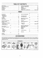
ACCESSORIES
These accessories and attachments were available when the unit was originally purchased They are also available at
most Sears retail outlets and service centers, Most Sears stores can order these items for you when you provide the model
number of your unit
Accessories
SAFETY
GOGGLES
HEARING
PROTECTION
SEMIAUTOMATIC
LINE HEAD
SPOOL
WITH LINE
BULK
LINE
SPARK
PLUG
I
AIR
FILTER
!
,080"
80 FT.
200 FT,
400 FT,,
-5-
-=0
GAS
CAN
SEARS
2-CYCLE
ENGINE OIL
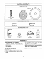
CARTON CONTENTS
Hardware shown full size
Grass Washer
(1) Fiat Washer
(4) Debris Shield
Screws
Parts bag contents not shown full size
Short Hex Key
Long Hex Key
Parts packed separately in carton
--_--'.'r
Operator's
Manual
Plastic
Debris Shield
Semi-automatic
Head
Engine Oil
ASSEMBLY
,, _,
L,Jl I
TOOLS
REQUIRED
,,,,1111
II
II1,,
FOR ASSEMBLY
• Torque Wrench (optional) - Reference torque values
are provided throughout this manua! for tightening
hardware_
• Long Hex Wrench
• Short HexWrench
• After removing the contents from the carton, check
parts against the Carton Contents list,
. Examine the parts for damage. Do not use damaged
parts,
o Notify Customer Assistance at 1-800-235-5878 immediately ff a part is missing or' damaged
TO REMOVE WEEDWACKER
FROM CARTON
NOTE: ii is normal to hear the fuel filter rattle in an empty
fuel tank.
•
-
Remove loose parts bag included witll Weedwacker.
Remove your Weedwacker from the packing material.
You may use the opened packing material as a work
surface.
°6-
ASSEMBLY
HOW TO ASSEMBLE
YOUR
- Place plastic debris shield under the gear box and align
screw holes. Make sure the widest part of the plastic
debris shield is pointing toward the engine.
o Insert the four shield screws through the gear box into
the plastic debris shield,,
• Tighten screws evenly and securely using the long, hex
key provided
WEEDWACKER
IF THIS UNIT IS RECEIVED ASSEMBLED,
ARNING:
REVIEW
ALL STEPS 1NTHIS ASSEMBLY
SECTION FOR PROPER ADJUSTMENT
AND CORRECT ASSEMBLY.
_
WHEN ADJUSTING THE ASSIST HANDLE
FOR COMFORT, BE SURE THAT THE
ASSIST HANDLE REMAINS BETWEEN
THE TRIGGER HOUSING ANDTHE SAFETY LABEL.
ASSIST HANDLE
ASSEMBLY
ONG HEX KEY__
ENGINE
GEAR BOX
DUST CUP
(MUST BE
REMOVED FOR
DEBRIS SHIELD
INSTALLATION)
PLASTIC
DEBRIS SHIELD
(Fig, 1)
NOTE: For pre-assembled units, simply loosen assist
handle knob and rotate assist handte to the operating
position, being sure to align between safety label and
throttle trigger housing,
• Rotate assist handle from left to right to tilt the angle of
the semi-automatic head when cutting a large, sloped
area such as a ditch bank.,
Tighten knob securely,
ARBOR SHAFT
Figure 2
SEMI-AUTOMATIC
•
•
TUBE
=
E HEAD
SCREW
.
•
KNOB
HEAD ASSEMBLY
(Fig. 3)
Ensure the plastic debris shield is in place and secured,
Install dust cup over the arbor shaft,,
Align the hole in the dust cup with the hofe in the center front of the gear box by turning the dust cup.
Install the grass washer over the arbor shaft. Make sure
the grass washer is against and curved over the dust cup,
Install the flat washer over the arbor shaft.
Start threading the semi-automatic head onto the arbor
shaft (counterclockwise),
holes
keep
the hex
arborkey
shaft
from turning,
Insert tothe
short
(provided)
into the aligned
Tighten the semi-automatic head while holding the
short hex key_
Remove the short hex key_
Figure 1
INSTALLING
(Fig. 2)
t_
L_
THE PLASTIC
GEARBOX
DEBRIS SHIELD
_._
WIDEST pA_LAMP _
OF SHIELD
"%_
TOWARD ENGINE_""_,_
THE LINE LIMITER IS SHARP AND CAN
WARNING:
CUT YOU. BE SURE TO WEAR GLOVES
WHILE WORKING WITH THE PLASTIC
DEBRIS SHIELD OR LINE LIMITER.
THE PLASTIC DEBRIS SHIELD MUST BE
PROPERLY INSTALLED FOR ALL LINE
TRIMMER USAGE. THE DEBRIS SHIELD
PROVIDES PARTIAL PROTECTION FROM
THE RISK OF THROWN OBJECTS TO THE
OPERATOR AND OTHERS,
WHEN INSTALLED
CORRECTLY, THE
PLASTIC DEBRIS SHIELD WILL BE IN
PROPER ALIGNMENT. FAILURE TO INSTALL THE DEBRIS SHIELD IN POSITION
SHOWN IN ILLUSTRATION CAN RESULT 1N
SERIOUS INJURY TO THE OPERATOR,
Lirns I or1
_ _,=_,-SCREW
_LI
_J
HOLE _SHORT
LY'3:FL_J
.Ix
_/
_,_"-_
,._- _v
CHECK
"
LIST
WASHER
F'AT
w ,S.ER
_,_,__-_,_j _,,,.=_.TRIMMER
('_ _----"'_:"_HEAD
_-__..._
/ DIRECTION
"'_'--.,..-_
_
TO INSTALL
Figure 3
o Check all fasteners, make sure they are tight and there
are no loose parts_
• Check to make sure the throttle cable is positioned correctly.
• With the unit held in the operating position, adjust the
assist handte up or down the tube for best comfort and
balance before first use,,
• Remove the packing cover from the arbor shaft if so
equipped
• Remove the dust cup from the arbor shaft (ref Fig. 2).
-7-
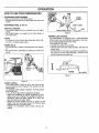
OPERATaON
KNOW YOUR WEEDWACKER
(Fig. 4)
READ THIS OPERATOR'S MANUAL AND SAFETY RULES BEFORE OPERATING YOUR WEEDWACKERo Compare
the illustrations with your unit to familiarize yourself with the location of the various controls and adjustments. Sav_ this
manual for future reference.
ON/OFF SWITCH
CAP
HANDLE
HANDLE
SAFETY
LABEL
FOAM
GRIP
'TUBE
TRIGGER
THROnLE
/
SEMI-AUTOMA_C
HEAD
FUEL CAP
PLASTIC
DEBRIS SHIELD
CHOKE
LEVER
LINE
L|MtTER
PRIMER BULB
MUFFLER
AND GUARD
Figure 4
The ON/OFF SWITCH is used to stop the engine.
The CHOKE LEVER is used for starting a cold engine
The STARTER ROPE HANDLE is used for starting the
engine
The THROTTLE TRIGGER controls engine speed
'The SEMI-AUTOMATIC HEAD contains spool of line which
advances when the head is tapped on the ground:
The PRIMER BULB circulates fuel to the carburetor°
The ASSIST HANDLE aids in the control of the uniL
The LINE LtMITER cuts trimmer line automatically to the
correct length,
-8-
OPERATION
HOW TO USE YOUR WEEDWACKER
STOPPING
YOUR ENGINE
° Move on/off switch to the "Off" position
o Uengine does not stop, move the choke lever clown (ful_
choke)
CONTROLS
ASSIST
HANDLE
(Fig. 5, 6 & 7)
SAFETY LABEL
THROTTLE TRIGGER
o The throttle trigger a{lows for variable control of engine
speed.
= The throttle trigger is actuated by the index finger on
your right hand
TUBE
ASSIST HANDLE KNOB
Figure
6
TRIMMER LINE ADVANCE
Your Weedwacker is equipped with a semi-automatic
trimmer headThe most efficient line length is the maximum length allowed by the line limiter
TO ADVANCE THE LINE:
, Operate the engine at full throttle_
, Hold the semi-automatic head parallel to and above a
grassy area.
, Tap the bottom of the semi-automatic head lightly on
the ground one time. Approximately 2 inches of line
will be advanced with each tap_
CHOKE
= The choke is set by moving the choke lever down fully
for cold or refueled engine starts..
PRIMER BULB
, The primer bulb is used to circulate fuel to the carburetor,
• The primer bulb is activated by pressing on it with your
thumb
CHOKE POSITIONS
TAP
THROTTLE
TRIGGER
_
!
€
I_
BULB
Figure 7
Figure 5
ASSIST HANDLE
The assist handle is used to aid in the control of the
unit, as well as a barrier between the operator and the
cutting head.
TO ADJUST THE ASSIST HANDLE FOR BALANCE
AND CONTROL:
° Turn off the engine before adjusting handlebar_
° Adjust the handlebar by sfightly loosening the handlebar knob and rotating the handlebar forward or
backward Adjust the assist handle up or down the
tube (but above the safety label).
= Rotate the assist handle from left to right to tilt the
angle of the semi-automatic head when cutting a larger
sloped area such as a ditch bank..
• Tighten the handlebar knob before starting the
engine
-9_
LI_E LiMITEF[
OPERATnON
BEFORE STARTING ENGINE:
40:1 2-CYCLE
AIR-COOLED
ENGINE OIL
CRAFTSMAN 40:1 2-cycle engine oil (AtR-COOLED) is
strongly recommended This oil is specially blended with
fuel stabilizers for increased fuel stability (extends fue! life
up to 5 times longer) and reduced smoke,
WARNING:
BE 'SURE TO READ THE FUEL SAFETY
INFORMATION IN THE SAFETY RULES
SECTION ON PAGE 2 OF THIS MANUAL,
BEFORE YOU BEGIN,
tf CRAFTSMAN
40:1 2-cycle engine oil (AIR-COOLED)
is not available,
use a good quality 2-cycle engine oil
(AIR-COOLED)
that has a recommended fuel mix ratio of
40:1,
IFYOU DO NOT UNDERSTAND
THE FUEL
SAFETY SECTION DO NOT ATT'EMPT TO
FUEL YOUR UNIT; SEEK HELP FROM
SOMEONE
WHO DOES UNDERSTAND
THE FUEL SAFETY SECTION OR CALL
THE CUSTOMER
ASSISTANCE
HOTLINE
AT 1-800-235-5878,
IMPORTANT!
Do no use:
. AUTOMOTIVE
OIL
,. BOAT OILS (NMMA, BIA, etc)
GASOLINE
The two-cycle engine on this product requires a fuel mixture of regular unleaded gasoline and a high quality 40:1
2-cycle engine oil (AIR-COOLED) for lubrication of the
bearings and other moving parts The correct fuel/oil mixture is 40:1 (see Fuel Mixture Chart). Too little oil or the
incorrect oil type will cause poor performance and may
cause the engine to overheat and seize,
These oils do not have proper additives for 2-cycle AIRCOOLED engines and can cause engine damage.
GASOLINE
AND OIL MIXTURE
Mix gasoline and oil as follows:
. Consult chart for correct quantities
• Do not mix gasoline and oil directly in the unit's fuel
tank
Gasoline and oil must be premixed in a clean approved
fuel container Always use fresh regular unleaded gasoline.,
FOR ONE GALLON:
. Pour 3.2 ounces of high quality, 40:1 2-cycle engine of!
(AIR-COOLED) into an empty, approved one gallon
gasoline container.
o Add one gallon of regular unfeaded gasoline to the gatIon container, then securely replace the cap.
= Shake the container_
,, The mixture is now ready lot use. Fuel stabilizer can be
added at this time if desired; foflow mixing instructions
on the label
This engine is certified to operate on unleaded gasoline,
IMPORTANT: Experience indicates that alcohol blended
fuels called gasohol (or using ethanol or methanol) can
attract moisture, which leads to oil/gas separation and
formation of acids during storage, Acidic gas can damage the fuel system of an engine while in storage_ To
avoid engine probtems, the fuel system should be emptied before storage for 30 days or longer Drain the gas
tank, then run the fuel out of the carburetor and fuel lines
by starting the engine and letting it run until it stops Use
fresh fuel next season See STORAGE instructions for
additional information Never use engine or carburetor
cleaner products in the luet tank or permanent damage
may occur
FUEL MIXTURE
CHART
40:1 Fuet:Oil Mix Ratio
I
Gasoline
1 gallon
2 5 gallons
32
80
FUEL STABILIZER
NOTE: Fuel containers may hold more than the specified
amounL If too much gasoline is in the container, the
resulting gas_to-oil fuel mixture will not be correct for
proper engine operation.
Fuel stabilizer is an acceptable alternative in minimizing
the formation of fuel gurh deposits during storage, Add
stabilizer to gasoline in fuel tank or storage container,
Always follow the fuel tank or storage container, Always
follow the fuel mix ratio found on the stabilizer container,
Run engine at least 5 minutes after adding stabilizer to
aitow the stabilizer to reach the carburetor, You do not
have to drain the fuel tank for storage if you are using
fuel stabilizer,
CRAFTSMAN 40:1 2-cycle engine oil (AIR-COOLED) is
specially blended with fuel stabilizers tf you do not use
this Sears oil, you can add a fuet stabitizer (such as
CRAFTSMAN No 33500) to your fuel tank.
-10-
OPERATION
STOPPING
YOUR ENGINE
,, ,Move the ON/OFF switch to the OFF position_
o If engine does not stop, move the choke lever down
(ful! choke).
&
WARNING:
THE SEMI-AUTOMATIC HEAD WILLTURN
WHEN THE ENGINE STARTS.
FOR SAFE STARTING AND OPERATION,
FOLLOW ALL SAFETY PRECAUTIONS tN
THIS
OPERATOR'S
MANUAL
AND
LABELS ON THE UNIT. DRESS PROPERLY BEFORE STARTING ENGINE.
AVOID ANY CONTACT WITH THE MUFFLER. A HOT MUFFLER CAN CAUSE
SERIOUS BURNS°
NOTE: If the engine has not started after 6 pulls (at half
choke), check to make sure the ON/OFF switch and the
choke lever are in lhe proper positions. Then, move the
choke lever to the full choke position and press the primer
bulb 6 times; pull the starter rope 2 more times Move the
choke lever to half choke and pull the starter rope until the
engine runs, but no more than 6 more pulls.
NOTE: If engine still has not started, it is probably flooded..
Proceed to "Difficult Starting and Flooded Engine"
- Allow the engine to run 10 seconds, then move the choke
lever to off choke Allow the unit to run for 30 more seconds at "Off Choke:' then release the throttle trigger.
NOTE: If engine dies with the choke lever at the "Off Choke"
position, move the choke lever to half choke and pull the
rope until the engine runs. Allow the unit to run for 30 more
seconds at "Off Choke:' then release the throttle trigger.
• To stop the engine, move the ON/OFF switch to fhe
OFF position
TO START ENGINE (Fig. 8 & 9)
COLD
START
ENGINE
AFTER
START AND WARM ENGINE
RUNNING
OUT OF FUEL
• Fue! engine with 40:1 fuel mix (32 oz. to ! gal gas)
Move 10 feet (3 meters) away from fueling site,
STARTING A WARM ENGINE
o Move choke lever to the "Off Choke" position
• Squeeze throttle trigger
o Pull starter rope until engine starts,
STARTING POSITION
ONtOFF
SWITCH
_':'-JL:I
,,.:'.=, J
Figure 8
- Move ON/OFF switch to the ON position
° Prime engine by pressing primer bulb six times.
- Actuate choke by moving the choke lever to the "Full
Choke" position.
- Rest engine and debris shield on ground, supporting
semi-automatic
- Squeeze and hold lhe throttle trigger. Keep the throttle
tdgger fully squeezed until the engine runs smoothly.
NOTE: When pulling the starter rope, do not use the full
extent of the rope as this can cause the rope to break
Do not let the starter snap back Hold the handle and Iet
the rope rewind slowly
• Pull starter rope sharply five times
The engine may sound as if it is trying to start before the
fifth pull. If so, go to the next step immediately°
• Move the choke lever to the "Half Choke" position.
• Pull the starter rope sharply unlil the engine runs, but
no more than six pulis..
Once the engine starts, allow the engine to run 15 seconds, then move the choke lever to "Off Choke: Allow the
engine to run for 30 more seconds at "Off Choke" before
releasing the throttte trigger.
- 11
Figure 9
DIFFICULT
STARTING
AND FLOODED
ENGINE
The engine may be flooded with too much fuel if it has
not started after 20 pulis
Flooded engines can be cleared of excess fuel with the
following procedure:
° Move the choke lever to the "Off Choke" position
, Squeeze and held the throttle trigger.
• Put! starter rope handle until engine starts
Starting could require pulling starter rope handle many
times depending on how badly unit is flooded,
tf engine still fails to start, refer to "TROUBLE SHOOTING" chart or call the 1-800 number listed on the front
cover of this manual..
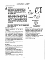
OPERATION
LINE TRIMMER
SAFETY
SAFETY
,i
,
THROWN
THE RAPIDLY MOVING LINE CAUSES OBJECTS TO BE
WARNING:
THROWN VIOLENTLY. THE DEBRIS SHIELD WILL NOT
PROVIDE COMPLETE PROTECTIONTO THE OPERATOR
OR OTHERS. THE OPERATOR MUST WEAR A SAFETY
FACE SHIELD OR GOGGLES. ALWAYS WEAR HEAVY,
LONG PANTS AND BOOTS. KEEP OTHERS AT LEAST 50
FEET (15 METERS) AWAY_
THIS UNIT WILL THROW OBJECTS AND CUT, KEEP OTHERS
INCLUDING CHILDREN, ANIMALS, BYSTANDERS AND
HELPERSAT LEAST50 FEET(15 METERS) AWAY FROM THE
OPERATOR AND UNIT. STOP THE ENGINE IF YOU ARE
APPROACHED.IN AREAS WHERE OTHER PEOPLE AND ANIMALS ARE PRESENT, SUCHAS NEAR SIDEWALKS, STREETS,
HOUSES, ETC., IT IS STRONGLY RECOMMENDED THAT THE
OPERATORUSE THE BUDDYSYSTEM; THAT IS, HAVE ANOTHER PERSON SERVE AS A "LOOK-OUT," KEEPING HIMSELF
AND OTHERS AT LEASTSOFEET (15 METERS) AWAY FROM
THE OPERATOR.
FACE
SHIELD
SEMI-AUTOMATIC
SEMI-AUTOMATIC HEAD PARTSTHA'r ARE CHIPPED, CRACKED
OR DAMAGED tN ANY OTHER WAY CAN FLY APART AND CAUSE
SERIOUS INJURY. DO NOT USE. REPLACE DAMAGED PARTS
BEFORE USING THE UNIT.
HEAD
USE ONLY GOOD QUALITY
REPLACEMENT PARTS
OPERATOR SAFETY
CUTTING SAFETY
o Always wear eye protection when operating, servicing, or
performing maintenance on your unit Refer to
"Accessories"
" Do not operate this unit when you are tired, ill, or under
the in!luence of alcohol, drugs or medication
o Always wear heavy, long pants, long sleeves, boots, and
gloves..Do not go barefoot, wear sandals, or short pants
Loose clothing, jewelry or clothing with loosely hanging
straps, ties, tassels, etc. can be caught in moving parts
Secure hair so it is above shoulder length. Being fully covered will help protect you from pieces of toxic plants such
as poison ivy thrown by the semi-automatic head, which
could be more of a hazard than touchingthe plant itself.
,, Do not swing the unit with such force that you are in danger of Iosing your balance.
= Never start or run the engine inside a closed room or
building. Breathing exhaust fumes can kill
o Keep handles free of oil and fuel
Inspectthe area to be cut before each use=Remove objects
(rocks, broken glass, nails, wire, string, etc) which can be
thrown or become entangled in the semi-automatichead
° Always keep the engine on the right side of yourbody
= Hold the unitfirmly with both hands
• Keep firm footing and balance. Do not ovePreach
, Keep the semi-automatichead below waist level
• Do not raise the engine above your waist.
° Keep all parts of your body away from the semi-automatic head and muffler when engine is running.
° Use only for jobs explained in this manual.
o Cut at full throttle,
° Cut from your right to your left
UNIT SAFETY
° Inspect the entire unit before each use Replace damaged parts. Check for fuel leaks and make sure all fasteners are in place and securely fastened.
• Use only ,080" diameter good quality monofilament line.
Never use wire, rope, or string, etc
o Be sure the plastic debris shield is properly attached
° Make sure semi-automatic head is properly installed and
securely fastened. Refer to "Assembly"
• Make carburetor adjustments with the drive shaft housing
supported to prevent the semi-automatic head from contacting any object.
• Keep others away when making carburetor adjustments.
• Use only good quality SEARS accessories or attachments
-12-
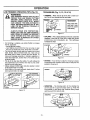
OPERATION
ILL
LINE TRIMMER
OPERATING
TIPS (Fig. 10)
=
I
.............
(Fig.
11, 12, 13 & 14)
• TRIMMING - Allow only the tip of the line to make contact.Do not force trimmerline intowork area.
TRIW.Q
_
....
REMEMBER
Keep semi automa_ head 3 inches
above the ground
whiletrimming
ALWAYS WEAR EYE PROTECTION,
NEVER LEAN OVER THE SEMI-AUTOMATIC
HEAD. ROCKS OR DEBRIS CAN RICOCHET
OR BE THROWN INTO EYES AND FACE
AND CAUSE BLINDNESS OR OTHER
SERIOUS INJURY°
Figure 11
SCALPING - The scalpingtechnique removes unwanted
vegetation_ Allow the tip of the line to strike the ground
around trees, post, monuments, etc This technique
increases line wear
• For trimming or scalping, use partial throttle to increase
line life, especially:
- during light duty cutting
-near objects around which the line can wrap or wear
Iine such as smalt posts, trees, fence wire or concrete
• The line will easily remove grass and weeds from around
wails, fences, trees and flower beds; but. it also can cut
the tender bark of trees or shrubs and scar fences. To
he_p avoid damage especially to delicate vegetation or
trees with tender bark, shorten line to 4-5 inches and use
at partial throttle
• The tip of the line does the cutting You will achieve the
best performance and minimum line wear by not crowding the line intocutting area
• Always release throttle trigger and allow engine to return
to idle speed when not cutting
• Hotd bottom of the semi-automatic head about 3 inches
above ground and at an angle.
j....../_'j"_
T=L
TECHNIQUES
USE
MINIMUM
SPEED AND DO NOT
WARNING:
CROWD THE LINE WHEN CUTTING
AROUND
HARD OBJECTS
(ROCK,
GRAVEL, FENCE POSTS, ETC.) WHICH
CAN DAMAGE THE SEMI-AUTOMATIC
HEAD, BECOME ENTANGLED tN THE
LINE, OR BE THROWN
CAUSING
A
SERIOUS HAZARD.
= LINE CROWDED
,_,,,..,-,-j.,3jTIP
OF LINE DOES
t=Lt,
SCALPING
/
,
f
3 INCHES
Figure t 2
• MOWING - Your trimmer is ideal for mowing in places
conventional lawn mowers cannot reach Keep the line
parallel to the ground
MOWING
•
,,",,
THE C_,T]'TING
Figure 13
' kl Hr
o SWEEPING - The fanning action of the rotating tine
can be used for a quick and easy clean up. Keep the
line parallel to and above the surfaces being swept
and move unit from side to side.
WRONG
Figure 10
Figure 14
-13-
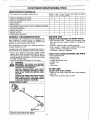
CUSTOMER RESPONSIBnLnTDES
MAINTENANCE
SCHEDULE
Before
Use
Fill in dates as you complete regular service
Alter
Use
Every Every Yearly Service Dates
5 Hrs. 25 Hrs.
Check for damaged or worn parts
12 V2
Check for loose fasteners & parts .........
Clean unit &labeis
Clean air filter
Clean/Inspect Spark...Arrestor Screen (if installed)and Muffler
Drive Shaft Lubrication
Replace spark plug
Replace fuel filter
F
¢.
J
,/
Check gearbox lubrication
GENERAL
RECOMMENDATIONS
BEFORE USE
CHECK
The warranty on this unit does not cover items that have
been subjected to operator abuse or negligence. To
receive full value from the warranty, the operator must
maintain unit as instructed in this manual
Some adjustments will need to be made periodically to
properly maintain your unit.
All adjustments in the "Service and Adjustments" section of
this manual should be checked at least once each season..
= Once a year, replace the spark plug, replace air filter
element and check semi-automatic head for wear. A
new spark plug and a clean or new air filter element
assures proper air-fuel mixture and helps your engine
run better and last ronger
- Follow the maintenance schedule in this manual.
_
PARTS
,, Semi-automatic head
° Assist handle
. Throttle handle
o Cyfinder and muffler cover
, Air filter cover
o Muffler
° Line Limiter
AFTER USE
CLEAN
UNIT AND LABELS
° Clean the unit using a damp cloth with a rnild detergent
after use.
• Wipe off the unit with a clean dry cloth.
CHART
AR BOX
OGeneral purpose lithium base grease..
(_)General purpose lithium base grease
OR WORN
CHECK FOR LOOSE FASTENERS AND PARTS
DISCONNECT THE SPARK PLUG BEFORE
WARNING
PERFORMING MAINTENANCE EXCEPT FOR
CARBURETOR ADJUSTMENTS.
REPLACE SEMI-AUTOMATIC HEAD PARTS
THAT ARE CRACKED, CHIPPED, OR DAMAGED IN ANY OTHER WAY BEFORE USING
THE UNIT,
INSPECl"THE ENTIRE UNIT. REPLACE DAMAGED PARTS. CHECK FOR FUEL LEAKS
AND MAKE SURE ALL FASTENERS ARE IN
PLACE AND SECURELY FASTENED.
_UBRICATION
FOR DAMAGED
- Semi-automatic head - replace semi-automatic head
parts that are bent, warped, cracked, or damaged in
any way
= Fuet cap - replace broken or leaking fuel cap_
. Debris shields - replace debris shields that are bent,
warped, cracked, or damaged in any way.
= Line limiter - missing or damaged
-14-
CUSTOMER
RESPONSiBILiTIES
.,,.i ..................
EVERY
5 HOURS
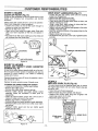
DRIVE SHAFT LUBRICATION
(Fig. 17)
• Loosen the gear box clamp screw and the locating
screw from the gear box.
: Remove the gear box from the tube,
Remove the drive shaft from the tube..
= Check drive shaft for broken wires, twists or kinks, and
replace if damage is found.
• Using a clean cloth, wipe surface of drive shaft thoroughly to remove any grease or dirt
• Apply a uniformcoat of lithium base grease to the entire
surface of the drive shaft.
, Inject the remaining contents of the grease tube into the
top of the tube°
• Replace drive shaft in the tube.
o Re-assemble the gear box to the tube. Tightemscrews
securely.
CLEAN AIR FILTER (Fig. 15)
A dirty air filter decreases the life and performance of the
engine and increases fuel consumption and harmful
emissions.
Always clean after 5 tanks of fuel or 5 hours of operation
Clean more frequently in dusty conditions,
" Loosen the screws on the air filter cover enough to
remove the cover from the engine
" Remove air filter from cover.
" Clean the air filter using hot soapy water, Rinse with
clean cool water. Squeeze air filter dry and replace in
cove r
, Re-install the air filter cover, making sure the choke exit
slot is placed over the choke lever
'_,.T___./AUBE
(_ _
_m:_-_'J_'_
CHOKE
_-_'_'_AIR
FILTER
Figure
TE THE DRIVE SHAFT
COVER
15
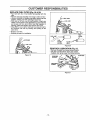
EVERY 25 HOURS
CLEAN
AND
INSPECT
SPARK
ARRESTOR
DRIVE SHAFT
SCREEN
(Fig. 16)
As the unit is used, carbon deposits buitd up on the muffler and spark arrestor screen (if installed), and must be
removed to avoid creating a fire hazard or affecting
engine performance.
TUBE
"_
Required cleaning is every 25 hours of operation or annually, whichever is less,
Figure 17
YEARLY
Replace the spark arrestor screen if breaks occur
REPLACE
CLEANING THE SPARK ARRESTOR SCREEN
• Loosen and remove the 2 muffler guard screws
• Remove the muffler guard
" Remove the muffler cover retaining springs
° Remove muffler diffuser and spark arrestor screen
assembly Notice the orientation of these parts for
reassembly
• Cfean the spark arrestor screen with a wire brush or
replace if breaks are found in the screen
,, Replace any broken or cracked parts
• Reinstall diffuser and spark arrestor screen assembly.
• Reinstall muffler cover and the two muffler cover retaining springs
• Reinstall muffler guard and the two muffler guard
screws (t5-20 in Ibs ).
SPARK PLUG (Fig. 18)
The spark plug should be replaced each year to ensure
the engine starts easier and runs better, Spark plug gap
should be .025"
,' Twist, then pull off spark plug boot.
• Remove spark plug from cy!lnder and discard
. Replace with correct spark plug and re-tighten with
spark plug wrench (10-12 ft,lb,)
• Reconnect spark plug boot,
rl
SPARKPLUG
BOOT
r-r'l D
_,_..,.L---SPARK
Figure 18
Figure 16
-15_
PLUG
CUSTOMER RESPONSIBaLgT E$
REPLACE
FUEL FILTER (Fig. 19 & 20)
,, Run fuel tank dry of fuel before proceeding with this
step.
o Remove fuel cap and allow it to hang to side of motor.
retainer,
holding
opening
and pull
out fuel cap
i Using
a small
pairit in
of tank
needle
nose pliers,
grasp
With cap out of tank, use a small section of bent wire
similar to that shown in the illustration to catch fuel line
and slowly pull from tank When fuel filter appears in
opening, grasp with fingers and remove from tank.
= Once fitter is out of tank, hold fuel line close to fuel illleE. Remove fuel filter by twisting and pulling at the
same time..
• LINE
,, Replace fuel fitter.
. Reverse process for installation
FUEL
FILTER
FUEL LINE
FILTh. ER
BARREL
NECK
Figure 20
GEAR
BOX LUBRICATION
(Fig. 21)
• Remove the gear box screw using a wrench
= Fill gear box with lithium base gear grease
o Replace and tighten gear box screw securely.
Figure 19
GEAR BOX
WASHER
/
GEAR BOX
SCREW
Figure 2!
_16-
SERVICE AND ADJUSTMENTS
STARTER
_
ROPE
(Fig. 22, 23 & 24)
DO
NOT REMOVE THE RETAINING TAB
DANGER:
AND SCREW OR THE PULLEY. THE
SPRING
BENEATH THE PULLEY IS
UNDER TENSION AND CAN FLY OUT
AND CAUSE SERIOUS INJURY. IF ANY
PART OF PULLEY HOUSING ASSEMBLY
IS DAMAGED (OTHER THAN ROPE), DO
NOT USE UNIT. TAKE IT TO YOUR SEARS
SERVICE CENTER/DEPARTMENTo
FRONT
SHROUD
NOSE CONE
SHROUD SCREWS
• Disconnect spark ptug wire
• Remove the screw and nut from the throttle trigger
housing.
. Hold throttle trigger away lrom the foam grip and
remove the barrel end of the throttle cable from the
throttle trigger.
. Carefully purl throttle cable out of foam grip
• LooseR nose cone screws.
• Remove tube from nose cone
• Remove front shroud screws
• Separate nose cone from engine
• If any old rope remains on unit, cut rope at starter handle to release tension,
• Remove the rope relainer screw and remove any
remaining rope
• Turn pultey clockwise as far as i! wilt goThen, turn the
pulley counterclockwise until the puiley notch is aligned
with the housing notch Next, turn the pulley one complete turn counterclockwise
until the notches are
aligned again.
• Insert the long hex key into the hole formed by the
notches to hold the pulley in position.
• Use a 42" length of replacement rope
• Move away 10 feet (3 meters) from the fuel tank with
the replacement rope. Use a match and melt both ends
of the rope to prevent fraying
= insert one end of rope through handle and secure with
a knot. Leave a 3/16" pigtail behind knot.
,, Insert the other end of the rope through the rope exit
hole into the inside of the housing, into the pulley and
up through the pulley hole.
, Wrap rope counterclockwise around the pulley ratchet
and tuck loose end under rope where it comes out of
the pulley hole. Leave a 1" tail laying flat on top of the
putfey between the retainer rib and the retainer screw/
post
= Install the rope retainer screw in the screw post
• Pull firmly on the rope to tighten it against the pulley
ratchet The rope tail must not extend beyond the raised
circle on the pulley to prevent interference with the
retaining tab..
• Hold rope taut at rope exit hole so it will not move;
remove long hex key
° Slowly feed rope intothe pulley housing
• To reassemble, reverse the above steps
W]RE
Figure 22
_ROPE
RETAINER SCREW
PULLEY
ROPE TAIL
POST
Figure 23
RETAINING
TAB AND
PULLEY,
NOTCH
RIB
PULLEY
RATCHET
CIRCLE
NOTCH
Figure 24
-17-
SERVICE AND ADJUSTMENTS
TRIMMER
LiNE REPLACEMENT
o Place the tap button over the spring and hub cylinder.
o Align the slots in the tap button with the fins in the base
of the hub, Push parts together,.
• Reinstall the spool and cover',
WARNING:
SEMI-AUTOMATIC
HEAD PARTS THAT
ARE CHIPPED, CRACKED, BROKEN, OR
DAMAGED IN ANY OTHER WAY CAN FLY
APART AND CAUSE SERIOUS INJURY. DO
NOT USE. REPLACE DAMAGED PARTS
BEFORE USING THE UNIT.
INSTALLING
NEW LINE ON SPOOL
To replace the line on existing spool:
, Follow"installing Spool with Line Aiready Wound" steps
and remove any line remaining on the spool
• Use a 25 loot length of SEARS _080" diameter line.
• Insert about 1/4 inch of the end of the line through the
hole in the inner rim of the spool Allow no more than
1/4 inch of line to extend beyond the rim to avoid interference with tapping action. Figure 30.
° Wrap the line on the spool as shown by the arrow,
NOTE: The line must be wrapped firmly and evenly for
proper line feed
. Follow"Installing Spool with Line Already Wound"steps
to complete assembly.
° If line breaks off or backs up in the semi-automatic
head, follow "Installing Spool with Line Already Wound"
steps. Pull slack in line until the line is tightly wound on
spool, leaving 4-6 inches of extended lineo Figure 30,,
THE LINE SAVER MUST BE INSTALLED
ONLY FROM THE INSIDE OF THE SEMIAUTOMATIC HEAD. IF INSTALLED ON THE
OUTSIDE
OF THE SEMI-AUTOMATIC
HEAD, THE LINE SAVER CAN FLY OFF
AND BECOME A DANGEROUS MISSILE.
USE ONLY .080" DIAMETER GOOD QUALITY LINE. NEVER USE WIRE, ROPE,
STRING, ETC.
USE ONLY SPECIFIED SEARS REPLACEMENT PARTS. USE OF OTHER BRANDS
OF REPLACEMENT PARTS CAN CAUSE
DAMAGE TO YOUR UNIT OR INJURY TO
THE OPERATOR OR OTHERS° DAMAGE/
INJURY CAUSED BY USE OF ACCESSORIEStA'I'f'ACHMENTS
NOT SPECIFICALLY RECOMMENDED BY SEARS WILL
NOT BE REIMBURSED.
I
INSTALLING
.
=
o
o
IMPORTANT: ALWAYS CLEAN DIRT AND DEBRIS
FROM SPOOL AND HUB WHEN PERFORMING ANY
TYPE MAINTENANCE
INSTALLING PRE-WOUND SPOOL
(Fig. 25, 26, 27, 28, 29 & 30)
THE SPOOL
insert line into line exit hole in the hub as shown, Figure
27
Align the notch with the line exit hole,
Push spool into the hub until it snaps into place.
Pull the end of the line to seat spool in hub.
Reinstall the cover,
SPOOL
LOCK TAB
• Hold the semi-automatic head as shown Press the two
tock tabs and remove cover Figure 25
o Remove the empty spool Refill or use a pre-wound
replacement spool
. Clean dirt and debris from alf parts Replace the spool
when the square corners on the lugs are rounded off,
reduced in size, or broken off. Figure 26
• Catch the line in the notch in the spool. Leave about 4
inches of line hanging from the spool Insert the end of
the line in the line exit hole Figure 27_
• Align the line and notch with the Une exit hole, Place
spool in hub Make sure trimmer line is not caught
between the rim of the spool and the hub.
NOTE: To set the spool in the hub, it may be necessary
to pull the line through the Iine exit hole until the spool
drops into place
. Align the lock tabs on the cover over the catches on the
hub Push the cover down onto the hub until the parts
snap together Figure 28.
= Check to make sure the lock tabs are properly fastened
as shown,
• Obtain the correct line length (6 inches) by pressing
tap button and pulling on the line again_ Figure 29°
NOTE: If tab button gets knocked out of the hub,
reassemble parts as toltows.
• Remove the cover and spool,
• Place the spring in the hub cylinder Figure 30
K
HUB
LOCKTAB
Figure 25
NORMALLUGS
WORN LUGS
Figure26
-18-
SERVICE AND ADJUSTMENTS
COVER RNGER OVER NOTCH
NOTCH
LINE EXIT HOLE
TAP BUTTON
Figure 27
Figure 29
CATCH
1N" OF
UNE
LOCK TABS
Figure 30
Figure 28
_19-
INNER
RIM
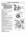
SERVICE AND ADJUSTMENTS
Carburetor adjustment is critical and tf done improperly can permanently damage the engine as well as
the carburetor, Please read all instructions and con.
suit the Troubleshooting
section of this manual
before beginning this process. If the engine does not
operate according to these instructions after repeatIng the adjusting steps, do not use the unit. For further assistance, please call our customer assistance
hotline at 1-800-235-5878,
° Starl the engine and operate for three (3) minutes to
warm up Go to "Adjusting Procedure".
WARNING:
MAKE CARBURETOR
ADJUSTMENTS
WITH THE LOWER END SUPPORTED TO
PREVENT SEMI-AUTOMATIC HEAD FROM
CONTACTING ANY OBJECT. HOLD UNIT
WITH YOUR HAND.
IDLE SPEED SCREW
Figure 31
ADJUSTING
THE SEMI-AUTOMATIC HEAD WILL BE
SPINNING DURING MOST OF THIS PROCEDURE,
WEAR YOUR PROTECTIVE
EQUIPMENT AND OBSERVE ALL SAFETY
PRECAUTIONS.
If engine does not start, it may be flooded If in doubt read
the section on flooded engine in the starting section of
this manual prior to beginning any adjustments.
MIXTURE ADJUSTMENT
, Support the lower end so the semi=automatic head is
off the ground and will not make contact with any
object, Be sure the trimmer line is extended to the maximum length allowed by the line limiter.
° Start the engine. Allow engine to idle, then squeeze
throttle trigger fully
NOTE: Perform steps below at full throttle
• Turn mixture screw counterclockwise to the limiter cap
stop.
= Run engine at full throttle for 30 seconds.
° I! engine is running rough, turn mixture screw clockwise
in 1/16th turn increments until engine just starts to run
smoothly.
• Do not attempt to adjust screw beyond stops as damage will occur,
. After completing adjustments, check for acceleration.
° tf the unit accelerates and runs smoothly, no further
adjustments
are necessary. 1! not, proceed to
"Acceleration Check"
The carburetor has been adjusted at the factory for sea
level conditions. Adjustments may become necessary if
the unit is used at significantly higher altitudes or if you
notice any of the following conditions:
. Engine will not idle. See "idle Speed Adjustment" and
'Mixture Speed Adjustment".
. Engine dies or hesitates when it should accelerate See
"Acceleration Check"
° Loss of cutting power which is not corrected by air filter cleaning. See "Mixture Speed Adjustment"
NOTE: There are two adjustments on the carburetor.
• The Idle Speed Adjustment.
, The Mixture AdjustmenL
PRESETS
PROCEDURE
IDLE SPEED ADJUSTMENT
. Allow the warm engine to idle
= Adjust the Idle Speed until the engine continues to run
without stalling,
- Turn screw clockwise to increase engine speed if
engine stalls or dies,
- Turn screw counterclockwise to slow engine down
- Follow instructionsin "Acceleration Check".
• No further adjustments are necessary if performance
is satisfactory
IN MIXTURE ADJUSTMENT,
RECHECK
IDLE SPEED AFTER EACH ADJUSTMENT.
CARBURETOR
AIR FILTER
COVER
(Fig. 31)
If your engine will not start due to suspected improper
carburetor adjustment, the following presets may be
required, If used, it is recommended that all steps within
the adjustment procedure be completed in order to
assure a properly set carburetor. If presets are not needed, proceed to section "Idle Speed Adjustment",
ACCELERATION CHECK
° Allow engine to idle
• Squeeze trigger fully
- if performance is satisfactory (engine accelerates
smoothlY)r no further adjustments are necessary.
- If the engme does not accelerate smoothly, turn
the mixture screw counterclockwise a small amount
(no mote than the width of the slot in the adjusting
screw).
• Repeat step above until smooth acceleration is
obtained. Do not attempt to adjust the screw beyond the
stop as damage will occur.
NOTE: It may be necessary to repeat "Idle speed
Adjustment"through "Acceleration Check,"_o obtain coro
rect adjustments
Very _mall adjustments can affect engine performance. It
is important to make slight adjustments and test pedormance before proceeding. Each adjustment should be no
more than 1/t6th of a turn
• Turn the mixture adjustment fully counterclockwise to
the limiter cap stops.,
; Turn idle speed adjustment clockwise one full turn,
If engine fails to start after pedorming carburetor presets, the unit may be flooded. Review the "Difficult
Starting" section of the manual If problems continue,
call the 1-800 number listed on the front cover of this
manual for further assistance°
- 20 -
STORAGE
Immediately prepare your unit for storage at the end of
the season or if it will not be used for 30 days or more.
....
_
ALLOW
THE ENGINE TO COOL, AND
WARNING:
SECURE THE UNIT BEFORE STORING
OR TRANSPORTING IN A VEHICLE,
STORE UNIT AND FUEL IN AN AREA
WHERE FUEL VAPORS CANNOT REACH
SPARKS OR OPEN FLAMES FROM
WATER HEATERS, ELECTRIC MOTORS
OR SWITCHES, FURNACES, ETCo
STORE UNIT WITH ALL GUARDS tN
PLACE. POSITION SO THAT ANY SHARP
OBJECT CANNOT ACCIDENTALLY CAUSE
INJURY TO PASSERS BYo
STORETHE UNIT OUT OFTHE REACH OF
CHILDREN.
GAS TRIMMER
STORAGE
INSTRUCTIONS
If your trimmer is to be stored for a period of time, clean
it thoroughly prior to storage. Remove any dirt, _eaves,oil,
grease, etc. Store in a clean dry area.
° Clean the entire unit
° Clean air filter. Refer to "Customer Responsibilities."
° Open the semi-automatic head assembly and clean
any dirt, grass or debris that has collected.
• Inspect the cutting line_Old cutting line may be chalky
or sticky to the touch. Remove and discard old line and
install fresh new line.
, Lightly oil external metal surfaces to prevent rust from
forming
• Re-assemble all loose parts, being sure that all handles
and guards are in place and are securely fastened
Replace any damaged parts_
• The recommended storage position is either vertically
with the fuel cap on top, or horizontally with the fuel cap
up_Do not store unit with the cutting attachment up.
, Hang the unit by the brackets under the motor housing
to avoid fuel leaks..Make sure the unit is positioned so
that the line limiter cannot cause injury
1_
FUEL SYSTEM
Never use engine or carburetor cleaner products in the
fuel tank or permanent damage may occur to fuel system
components. Follow these instructions:
= Drain the fuel from the unit into an approved fuel container.
• Drain the fuel lines and carburetor by starting the
engine and letting it run until it stops
• Allow the engine to cool before storage
IMPORTANT: It is important to prevent gum deposits
from forming in essential fuel system parts such as the
carburetor, fuel filter, fuel hose or tank during storage
Also, experience indicates that alcohol blended fuels,
those that use ethano_ or methanol (called gasohol or
oxygenated fuel), can attract moisture and form acidic
gas which will damage your engine .To avoid engine problems, the fuel system should be emptied before storage
of 30 days or longer.
Fue! stabilizer is an acceptable alternative in minimizing
the formation of fuel gum deposits during storage. Add
stabilizer to the gasoline in the fuel tank or fuel storage
container Always follow the mix instructionsfound on stabilizer containers Run engine at least 5 minutes after
adding stabilizer to allow the stabilizer to reach the carburetor
CRAFTSMAN 40:1 2-cycle engine oil (AIR-COOLED) is
specially blended with fuel stabilizer. If you do not use
this Sears oil, you can add a fuel stabilizer (such as
CRAFTSMAN Noo33500) to your fuei tank.
INTERNAL
ENGINE
• Remove spark plug and pour t teaspoon of 40:1 2cycle engine oil (AIR*COOLED) through the spark plug
opening. Slowly pull the starter rope 8 to 10 times to
distribute oil to inner engine surfaces
- Replace spark plug with a new one of the recommended
type and heat range Refer to "Product Specifications."
• Clean air filter. Refer to "Customer Responsibilities."
, Re-install all covers and hardware removed for access;
tighten all screws and fasteners_
° Check entire unit for loose screws, nuts, and bolts
Replace any damaged, broken, or worn parts
• Lightly oil external metal surface to prevent rust from
forming.
• Use fresh fuel having the proper gasoline to oil ratio at
the beginning of the next season
WHEN HANDLING LINE LIMITER. THE
CAUTION:
WEAR AND
PROTECTIVE
BLADE
IS SHARP
CAN CUTGLOVES
YOU°
OTHER
- Do not store gasoline from one season to another.
• Replace your gasoline can if your can starts to rust Rust
and/or dirt in your fuel system will cause problemso
° Store your unit in a well ventilated area and covered, if
possible, to prevent dust and dirt accumulation Do not
cover wilh plastic° Plastic cannot breathe and will
induce condensation and eventual rust or corrosion.
IMPORTANT: NEVER COVER UNIT WHILE
AND EXHAUST AREAS ARE STILL WARM
- 21 -
ENGINE
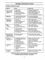
TROUBLE SHOOTING POnNTS
TROUBLE
SHOOTING CHART
SYMPTOM
CAUSE
CORRECTION
1 Fuel tank empty_
2 Engine flooded.
3_ Spark plug not tiring.
4, Fuel not reaching carburetor.
5. Carburetor requires adjustment.
6, None of the above,
I_ Fill tank with correct fuel mixture.
2. See "Starting Instructions",
3,. Install new plug!check ignition switch
4. Replace fuel filter; inspect fuei line,
5. See "Carburetor Adjustments°"
6, Contact your SEARS Service Center/DepL
Engine will not
idle properly.
t Carburetor set too fast or too stow
2 Carburetor requires adjustment
3 None of the above
1 See"Carburetor Adjustments."
2. See "Carburetor Adjustments."
3 Contact your SEARS Service Center/DepL
Engine will not
accelerate, lacks
power,or dies
under a load.,
1
2
3,
4,
5.
I Clean or replace air filter,,
2oClean or replace spark plug and re-gap,
3 See "Carburetor Adjustments."
4 Contact your SEARS Service CentedDepL
5 Contact your SEARS Service Center/Depto
Engine
smokes
excessively
1, Air filter dirty.
2. Fuel mixture incorrect.
3, Carburetor requires adjustment.
1. Clean or replace air filter,
2 Refuef with correct fuel mixture,
3. See "Carburetor Adjustments:
Engine
runs hot
1
2.
3,
4,
5.
1 See "Fueling Your Unit."
2 Replace with correct plug.
3 See Carburetor Adjustments."
4 Use only .080" diameter cutting line.
5. Contact your SEARS Service Center/Dept.
Semi-automatic head
slops under a load
or does not turn when
engine is accelerated.
1, Drive shaft not engagedv
2, Drive shaft broken.
1. See "Assembly," "Tube", insert fully,
2. Contact your SEARS Service CentedDepL
Line does not
advance or breaks
while cutting.
1 Line improperly routed in head.
2 Line improperly wound onto spool.
3 Line size incorrect.
4_ Old cutting line.
5_ Too little line outside head.
6 Dirt accumulated in cover,
1 Remove cover. Check line routing.
2. Rewind line tightly and evenly.
3 Use only .080" diameter line.
4 Replace with new cutting lineo
5. Remove cover. Pull 4" of line to outside.
6, Clear] cover_
7_Rewind in correct direction.
Engine will not start or
will run only for a
few seconds after
starting,.
Air filter dirty
Spark plug foutedv
Carburetor requires adjustment.
Muffler outlets plugged
None of the above.
Fuel mixture incorrect,
Spark plug incorrect
Carburetor set too high (lean),
Wrong diameter cutting line.(too large)
None of the above,
7 Line wound in wrong direction,
Line welds onto
spool
1_Line size incorrecL
2,, Old cutting line,_
3, Incorrect spool.
4. Crowding line against materiai
being cut.
1. Use only 080" diameter line,.
2 Replace with new cutting line.,
3 Use proper spool,
4 Cut with tip of line.
Line pulls back
into head.
1 Too little line outside of head,
2. Old cutting tine_
1 Remove cover. Pull 4" of line to outside.
2, Replace with new cutting line.
If situations occur which are not covered in this manual, use care and good judgemenL
If you need assistance, contact your SEARS Service Center/Department or the
CUSTOMER ASSISTANCE HOTLINE AT 1-800.235_5878.
_22_