1
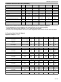
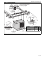
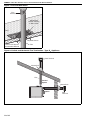
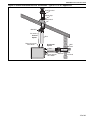
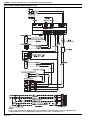
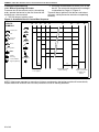
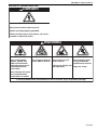
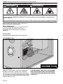
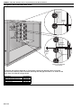
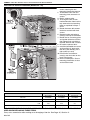
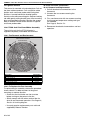
FOR YOUR SAFETY
If you smell gas:
1. Open windows.
2. DO NOT try to light any appliance.
3. DO NOT use electrical switches.
4. DO NOT use any telephone in
your building.
5. Extinguish any open flame.
6. Leave the building.
7. Immediately call your local gas
supplier after leaving the building.
Follow the gas supplier’s
instructions.
8. If you cannot reach your gas
supplier, call the Fire Department.
Combat
®
Compact Tubular Unit Heaters
Installation, Commissioning,
Operation & Service Manual
WARNING
Models CTCU 7
CTCU 11
CTCU 15
CTCU 22
CTCU 27
CTCU 32
Fire Hazard
Keep all flammable objects, liquids and
vapours the minimum required
clearances to combustibles away from
heater.
Some objects will catch fire or explode
when placed close to heater.
Failure to follow these instructions can
result in death, injury or property
damage.
WARNING
Improper installation, adjustment, alteration, service
or maintenance can result in death, injury or property
damage. Read the installation, operation and service
manual thoroughly before installing or servicing
this equipment.
Installation must be done by a registered installer/
contractor qualified in the installation and service
of gas-fired heating equipment or your gas supplier.
© 2012 Roberts-Gordon Europe Limited
Installer
Please take the time to read and understand
these instructions prior to any installation.
Installer must give a copy of this manual to the owner.
Owner
Keep this manual in a safe place in order to provide
your serviceman with necessary information.
Roberts-Gordon Europe Limited
Unit A, Kings Hill Business Park
Darlaston Road, Wednesbury
West Midlands WS10 7SH UK
Telephone: +44(0)121 506 7700
Fax: +44 (0)121 506 7701
Service Telephone: +44 (0)121 506 7709
Service Fax: +44 (0)121 506 7702
E-mail: [email protected]
E-mail: [email protected]
www.rg-inc.com
P/N 111100UK Rev F 03/12
www.combat.co.uk
TABLE OF CONTENTS
SECTION 1: Heater Safety...................................................... 2
1.1 Manpower Requirements ............................................. 2
1.2 Safety Labels and Their Placement ............................. 2
SECTION 2: Installer Responsibility ..................................... 4
2.1 Clearances to Combustibles ........................................ 4
2.2 Corrosive Chemicals.................................................... 4
2.3 National Standards and Applicable Codes .................. 4
SECTION 3: Clearances to Combustibles............................. 5
3.1 Required Clearances to Combustibles......................... 5
SECTION 4: Critcal Considerations ...................................... 7
4.1 Ventilation .................................................................... 7
4.2 Gas Supply .................................................................. 7
4.3 Electrical Supply .......................................................... 7
4.4 Flue.............................................................................. 7
SECTION 5: Specifications .................................................... 8
5.1 CTCUA (All Models) .................................................... 8
5.2 General Technical Data Table (All Models) .................. 9
5.3 Technical Data Table (All Models)................................ 9
SECTION 6: Heater Installation............................................ 10
6.1 General ...................................................................... 10
6.2 Basic Information ....................................................... 10
6.3 Location and Suspension .......................................... 10
6.4 Handling .................................................................... 10
6.5 Suspension and Shelf Mounting ................................ 10
6.6 Wall Mounting ............................................................ 10
SECTION 7: Flue Installation ............................................... 13
7.1 Flue Installation .......................................................... 13
7.2 Changing Flue and Air Intake Orientation .................. 13
7.3 Type C12, C32 & C62 Appliance..................................... 13
7.4 Type B22 Appliance ..................................................... 13
SECTION 8: Air Supply......................................................... 16
8.1 Room Sealed Installation........................................... 16
8.2 Open Flued Installation.............................................. 16
8.3 Building Ventilation .................................................... 16
SECTION 9: Gas Pipe Work.................................................. 17
9.1 Connections............................................................... 17
SECTION 10: Wiring and Electrical Information................. 19
10.1 Electrical Supply ...................................................... 19
10.2 Remote Controls ...................................................... 19
10.3 CTCUA Wiring Diagram (Models 7-32) .................... 20
SECTION 11: Commissioning .............................................. 21
11.1 Pre-Commission Checks .......................................... 21
11.2 Gas Supply ............................................................... 21
11.3 Mechanical Checks................................................... 21
11.4 Begin Commissioning ............................................... 22
11.5 Combustion Testing .................................................. 23
11.6 Turning Off the Heater .............................................. 23
11.7 External Controls ...................................................... 23
11.8 Complete the Commissioning................................... 24
11.9 Instruction to the User .............................................. 24
SECTION 12: User Instructions ........................................... 25
12.1 User Instructions...................................................... 25
12.2 Heater Operation ..................................................... 25
12.3 Common User Controls ........................................... 25
12.4 Lighting Instructions................................................. 26
12.5 Simple Fault Finding ................................................ 26
SECTION 13: Servicing .........................................................27
13.1 Servicing Instructions...............................................27
13.2 Burner Maintenance.................................................27
13.3 Fan/Motor Assembly Maintenance ...........................27
13.4 Heat Exchanger Maintenance ..................................27
13.5 Gas Control Valve Maintenance ...............................28
13.6 Flue Fan ...................................................................28
13.7 Maintenance Checklist .............................................28
SECTION 14: Conversion Between Gases ..........................30
14.1 General ....................................................................30
14.2 Burner Conversion ...................................................30
14.3 Gas Valves ...............................................................30
SECTION 15: Troubleshooting .............................................31
15.1 General ....................................................................32
15.2 Troubleshooting For Automatic Ignition Burner
Systems....................................................................33
15.3 Troubleshooting for Flame Supervision System .......34
15.4 Troubleshooting for Solenoid Valves ........................34
15.5 Troubleshooting for Main Fan ...................................35
SECTION 16: Removal and Replacement Parts..................36
16.1 Gas Valve .................................................................36
16.2 Burner Compartment ...............................................37
16.3 Ignition Electrode and Flame Probe .........................38
16.4 Flue Fan Vertical Installation (Models 7 - 15) ...........39
16.5 Flue Fan Vertical Installation (Models 22 - 32) .........40
16.6 Pressure Switch........................................................41
16.7 Ignition Control .........................................................42
16.8 CTCUA Axial Fan/Guard/Motor Assembly ...............42
16.9 Fan and Limit Thermostats ......................................42
© 2011 Roberts-Gordon Europe Ltd
All rights reserved. No part of this work covered by the copyrights herein may be reproduced
or copied in any form or by any means - graphic, electronic, or mechanical, including
photocopying, recording, taping or information storage and retrieval systems - without the
written permission of Roberts-Gordon Europe Ltd.
Printed in U.K.
TABLE OF FIGURES
Figure 1: Front and Back Panel Label Placement ..................... 2
Figure 2: Side Panel Label Placement...................................... 3
Figure 3: Installation Clearances and Clearances to
Combustibles............................................................. 6
Figure 4: Suspension Methods ............................................... 11
Figure 5: Shelf Mounting and Hanging Suspension................ 12
Figure 6: Vertical Louvres (Optional) ...................................... 12
Figure 7: Flue and Roof Detail ................................................ 14
Figure 8: Vertical and Horizontal Flue Termination Type B22 Appliance .................................................. 14
Figure 9: Vertical and Horizontal Flue Termination Type C12 C32 & C62 Appliances ................................. 15
Figure 10: Gas Connection with Stainless Steel Flex
Connector .............................................................. 18
Figure 11: Automatic Burner Control Box Sequence............... 22
Figure 12: Gas Valve for Heater (Models 7 - 32)..................... 23
Figure 13: Heater Operating Sequence .................................. 25
COMBAT® Compact Tubular Unit Heaters are high efficiency heaters and are listed on
the Enhanced Capital Allowance Scheme ’Energy Technology Product List’. The ETL
symbol is a UK registered certification mark of The Carbon Trust.
Product Approval
ROBERTS GORDON® appliances have been tested and CE certified as complying with the essential
requirements of the Gas Appliance Directive, the Low Voltage Directive, the Electromagnetic
Compatibility Directive and the Machinery Directive for use on natural gas and LPG when installed,
commissioned and maintained in accordance with these instructions.
These instructions refer to appliances designed to operate in the European Union.
Appliances designed for other countries (Non-European Union) are available on request.
This appliance must be installed in accordance with the local and national codes in force and used
only in a sufficiently ventilated space, as specified in these instructions.
Before installation, check that the local gas distribution systems, nature of gas and pressure, and
adjustment of the appliance are compatible.
1 of 42
COMBAT® CTCU UNIT HEATERS INSTALLATION OPERATION AND SERVICE MANUAL
SECTION 1: HEATER SAFETY
Your Safety is Important to Us!
This symbol is used throughout the
manual to notify you of possible fire,
electrical or burn hazards. Please pay
special attention when reading and
following the warnings in these sections.
Installation, service and annual inspection of heater
must be done by a registered installer/contractor
qualified in the installation and service of gas-fired
heating equipment.
Read this manual carefully before installation,
operation, or service of this equipment.
This heater is designed for heating non-residential
indoor spaces. Do not install in residential spaces.
These instructions, the layout drawing, local codes
and ordinances, and applicable standards that apply
to gas piping, electrical wiring, venting, etc. must be
thoroughly understood before proceeding with the
installation.
Protective gear is to be worn during installation,
operation and service. Thin sheet metal parts have
sharp edges. To prevent injury, the use of work
gloves is recommended. The use of gloves will also
prevent the transfer of body oils from the hands.
Figure 1: Front and Back Panel Label Placement
Description
Logo Label
Address Label
Lockout Reset Label
Rating Plate Label
Connection Diagram Label
2 of 42
Part Number
91040030
91040006
91038303
91040001
91040022
Before installation, check that the local distribution
conditions, nature of gas and pressure, and
adjustment of the appliance are compatible.
The heater must be applied and operated under the
general concepts of reasonable use.
This appliance is not intended for use by persons
(including children) with reduced physical, sensory
or mental capabilities, or lack of experience and
knowledge, unless they have been given
supervision or instruction concerning use of the
appliance by a person responsible for their safety.
Children should be supervised to ensure that they
do no play with the appliance.
For additional copies of the Installation, Operation
and Service Manual, please contact RobertsGordon Europe Limited.
1.1 Manpower Requirements
To prevent personal injury and damage to the
heater, two persons will be required for installation
.
1.2 Safety Labels and Their Placement
Product safety signs or labels should be replaced by
the product user when they are no longer legible.
Contact Roberts-Gordon for obtaining replacement
signs or labels. See Page 2, Figure 1 through Page
3, Figure 2.
SECTION 1: HEATER SAFETY
Figure 2: Side Panel Label Placement
Description
Lighting Label
Wiring Diagram Label
Part Number
91040002
91040020
3 of 42
COMBAT® CTCU UNIT HEATERS INSTALLATION OPERATION AND SERVICE MANUAL
SECTION 2: INSTALLER RESPONSIBILITY
• To install the heater, as well as the gas and electrical supplies, in accordance with applicable
specifications and codes. Roberts-Gordon
recommends the installer contact a local
building inspector, Fire Officer or insurance
company for guidance.
• To use the information given in the manual
together with the local and national codes to
perform the installation.
• To install the heater in accordance with the
clearances to combustibles of this heater.
• To furnish all needed materials not furnished
as standard equipment.
• To plan location of supports, flues and air
intakes.
• To provide access to burners for servicing.
• To provide the owner with a copy of this
installation, commissioning, operation and
service manual.
• To never use heater as support for ladder or
other access equipment and never hang or
suspend anything from heater.
• To ensure that there is sufficient ventilation in the
area to comply with the requirements of
all relevant local and national codes.
• To safely and adequately install heater using
materials with a minimal working load of 33 kg.
• To ensure the heater is placed in an approved
application.
2.1 Clearances to Combustibles
A laminated wall tag is available for the heater as a
permanent reminder of the safety instructions and
the importance of the required clearances to
combustibles. Affix the tag by peeling off the backing
of the adhesive strips on the rear surface and
position the tag on a wall near the heater (e.g.
thermostat or ROBERTS GORDON® Controller).
A copy of the wall tag (P/N 91040029) is illustrated
on the back cover. Know your model number and
installed configuration. Model number and installed
configuration are found on the burner and in the
Installation, Operation and Service Manual. Write
the largest clearance dimensions with permanent
ink according to your model number and
configuration in the open spaces on the tag.
4 of 42
2.2 Corrosive Chemicals
CAUTION
Product Damage Hazard
Do not use heater in area containing
corrosive chemicals.
Refer to appropriate Material Safety Data
Sheets (MSDS).
Failure to follow these instructions can result
in product damage.
Roberts-Gordon cannot be responsible for ensuring
that all appropriate safety measures are undertaken
prior to installation; this is entirely the responsibility
of the installer. It is essential that the contractor, the
sub-contractor, or the owner identifies the presence
of combustible materials, corrosive chemicals or
halogenated hydrocarbons* anywhere in the
premises.
* Halogenated Hydrocarbons are a family of chemical
compounds characterized by the presence of halogen
elements (fluorine, chlorine, bromine, etc.). These compounds are frequently used in refrigerants, cleaning
agents, solvents, etc. If these compounds enter the air
supply of the burner, the lifespan of the heater components will be greatly reduced. Warranty will be invalid if
the heater is exposed to halogenated hydrocarbons.
2.3 National Standards and Applicable Codes
All appliances must be installed in accordance with
the latest revision of applicable standards and local
and national codes. This refers also to the electric,
gas and venting installation. Note: Additional
standards for installations in public garages, aircraft
hangars, etc. may be applicable.
SECTION 3: CLEARANCES TO COMBUSTIBLES
SECTION 3: CLEARANCES TO COMBUSTIBLES
WARNING
•
Fire Hazard
Keep all flammable objects, liquids and
vapours the minimum required clearances to
combustibles away from heater.
•
Some objects will catch fire or explode when
placed close to heater.
Failure to follow these instructions can result
in death, injury or property damage.
3.1 Required Clearances to Combustibles
Clearances are the required distances that
combustible objects must be away from the heater
to prevent fire hazards. Caution should be used
when running the system near combustibles.
Combustibles are materials, which may catch on fire
and include common items such as wood, paper,
rubber, fabric, etc. Maintain clearances to
combustibles at all times for safety.
Clearances around the heater and flue must be as
indicated on Page 6, Figure 3, to ensure access for
servicing, and correct operation. If clearances to
combustibles are not indicated, then installation
clearances apply.
Check the clearances on each burner for the model
heater being installed to make sure the product is
suitable for your application and the clearances are
maintained. Read and follow the safety guidelines
below:
• Keep petrol or other combustible materials
including flammable objects, liquids, dust or
vapours away from this heater or any other appliance.
• The stated clearances to combustibles represents a surface temperature of 32°C (90° F)
above room temperature. Building materials with
a low heat tolerance (such as plastics, vinyl siding, canvas, tri-ply, etc) may be subject to degradation at lower temperatures. It is the installer’s
responsibility to assure that adjacent materials
are protected from degradation.
• Maintain clearances from heat sensitive equipment and workstations.
• Maintain clearances from vehicles parked below
the heater.
• Maintain clearances from swinging and overhead doors, overhead cranes, vehicle lifts, parti-
•
•
tions, storage racks, hoists, building
construction, etc.
In locations used for the storage of combustible
materials, signs must be posted to specify the
maximum permissible stacking height to maintain required clearances from the heater to the
combustibles. Signs must be posted adjacent to
the heater thermostat. In the absence of a thermostat, signs must be posted in a conspicuous
location.
Consult local Building Inspector, Fire Insurance
Carrier or other authorities for approval of proposed installation when there is a possibility of
exposure to combustible airborne materials or
vapours.
Hang heater in accordance to the minimum
suspension requirements on Page 10, Section 6
and Page 11, Figure 4 through Page 12, Figure
5.
Affix the tag on a wall near the heater.
5 of 42
COMBAT® CTCU UNIT HEATERS INSTALLATION OPERATION AND SERVICE MANUAL
Figure 3: Installation Clearances and Clearances to Combustibles
* Heaters may be mounted at a higher level if destratification
**80 cm is necessary to service
fans are installed.
heater.
The heater must always be installed at least 1.8 m above the floor.
The flue pipe must have clearance from combustibles by 5 cm.
If installed at low levels where individuals can come in contact with hot heat exchanger components,
adequate guarding must be provided.
All distances are minimum clearance requirements for service access, air flow and safety.
6 of 42
SECTION 4: CRITCAL CONSIDERATIONS
SECTION 4: CRITCAL CONSIDERATIONS
4.1 Ventilation
WARNING
Carbon Monoxide Hazard
Heaters may be installed vented or unvented.
Vented heaters must be vented outdoors.
Unvented heaters must be installed in
buildings with ventilation rates as per
section 7.
Failure to follow these instructions can result
in death or injury.
It is important to ensure that there is adequate air
circulation around the heater to supply air for
combustion, ventilation and distribution in
accordance with local and national codes.
4.2 Gas Supply
4.3 Electrical Supply
DANGER
Electrical Shock Hazard
Disconnect electric before service.
Heater must be properly grounded.
Failure to follow these instructions can result
in death or electrical shock.
A permanent 230 V 50 Hz 1Ø electrical supply is
required at the main electrical terminals. The heater
also requires suitable energy controls in accordance
with Section 10.
4.4 Flue
Choose heater siting to allow for the proper location
of the flue. Each heater must be fitted with an
individual and correctly sized sealed flue system
(See Page 13, Section 7).
No other appliance may be connected to the flue.
For room sealed installation, the air intake must be
the same size sealed system and the flue/air intake
must terminate at an approved concentric wall or
roof terminal.
It is important that the gas supply pipe is sized
correctly to provide the inlet pressure as stated on
the heater data plate. The gas supply pipe and
electrical connections must not support any of the
heater's weight.
7 of 42
COMBAT® CTCU UNIT HEATERS INSTALLATION OPERATION AND SERVICE MANUAL
SECTION 5: SPECIFICATIONS
5.1 CTCUA (All Models)
Top View
14
448
265
4 x M10 Captive Nuts Provided
422
Air Intake
(Optional Position)
463
Flue
(Optional Position)
120
Mounting
Holes
C
171
Rear View
End View
4 x M10 Captive Nuts Provided
Air Intake
Flue on Model 22
448
660
514
D
120*
171
B
A
Air Intake
Electrical
Connection
Lockout Reset
Gas Supply
Mounting
Holes
45
85
728
* 140 for 27 - 32
Dimension Data - CTCUA (All Models)
A
Height
B
Mounting Hole Spacing
C
Centre of Flue (Top Option)
D
Centre of Flue
Weight
8 of 42
Model
CTCU-7
CTCU-11
CTCU-15
CTCU-22
CTCU-27 / 32
mm
(in)
mm
(in)
mm
(in)
mm
(in)
304
(12.0)
239
(9.4)
151
(5.9)
68
(2.7)
304
(12.0)
239
(9.4)
151
(5.9)
68
(2.7)
450
(17.7)
385
(15.2)
151
(5.9)
68
(2.7)
450
(17.7)
385
(15.2)
172
(6.8)
46
(1.8)
578
(22.8)
513
(20.2)
149
(5.9)
59
(2.3)
kg
28
30.5
38.5
41
52.3
SECTION 5: SPECIFICATIONS
5.2 General Technical Data Table (All Models)
Model
CTCU-7
CTCU-11
CTCU-15
CTCU-22
CTCU-27 / 32
Total Electrical Load
W
260
274
336
384
345
Run Current
A
1.1
1.2
1.5
1.7
1.5
Start Current
A
1.7
1.8
2.5
2.9
2.6
Air Flow
m3/h
1120
1220
2710
2750
4474
Air Throw
m
9
12
14
16
16
[NR]
dB(A)
[31]
37
[35]
41
[39]
45
[42]
48
[42]
48
mm Ø
80
80
80
80
100
m
2.5
4
5
5
5
CTCUA, Axial Fans
Sound Pressure Level at 3 m
Flue and AIr Intake
Flue and Air Intake Size
*Maximum Straight Flue/Air Intake
Electrical load at 230 V 50 Hz measured by calculating from total run current of appliance.
* Do not exceed the maximum length of flue stated or heater may not operate properly.
Reduce the maximum length stated by 1 m for each 90° bend installed.
**If minimum air flow requirements are not met, then temperature limit devices will shut down the heater.
5.3 Technical Data Table (All Models)
Appliance Category II 2H/L 3B/P
Model
CTCU-7
CTCU-11
CTCU-15
CTCU-22
CTCU-27
CTCU-32
Heat Input
Gross CV
kW
(Btu/h) x (1000)
8.5
29
13.4
46
18.3
62
27.5
94
33
113
38.5
131
Heat Input
Net CV
kW
(Btu/h) x (1000)
7.7
26
12.1
41
16.5
56
24.8
85
29.7
101
34.7
118
Approximate
Heat Output
kW
(Btu/h) x (1000)
7.1
24
11.1
38
15.1
52
23
78
27.2
93
31.7
108
Natural Gas (G20) Data - Inlet Pressure 20 mbar (7.8 in WG) Min. 17 mbar (6.8 in WG) Max. 25 mbar (10 in WG)
Burner Pressure
Gas Rate
mbar
9.5
9.5
9.5
9.5
9.0
9.0
3
0.8
29
1.3
45
1.7
62
2.6
93
3.1
110
3.6
127
m /h
ft3/h
Natural Gas (G25) Data - Inlet Pressure 25 mbar (10 in WG) Min. 20 mbar (7.8 in WG) Max. 30 mbar (12 in WG)
Burner Pressure
Gas Rate
mbar
9.0
9.0
9.5
9.2
9.2
9.3
3
0.9
33
1.5
52
2.0
72
3
108
3.6
127
4.2
148
m /h
ft3/h
LPG / Propane (G31) Data - Inlet Pressure 37 mbar (14.6 WG) Min. 25 mbar (10 in WG) Max. 45 mbar (18 in WG)
Alternative where permitted 50 mbar (20 in WG) Min. 42.5 bar (17 in WG) Max. 57.5 mbar (23 in WG)
Burner Pressure
mbar
25.6
29.4
29.4
28.6
29.9
29.9
Gas Rate
m3/h
kg/h
0.3
0.59
0.5
0.93
0.7
1.27
1
1.91
1.2
2.3
1.4
2.68
LPG / Butane (G30) Data - Inlet Pressure 29 mbar (11,4 in WG) Min. 20 mbar (7.8 in WG) Max. 35 mbar (13.8 WG)
Burner Pressure
mbar
19.2
21.9
22.9
21.4
21.4
22.4
Gas Rate
m3/h
kg/h
0.2
0.6
0.4
0.94
0.5
1.28
0.8
1.93
.9
2.31
1.1
2.7
R - 1/2"
R - 1/2"
R - 1/2"
R - 1/2"
R - 1/2"
Gas Connection
CTCUA
R - 1/2"
Gas rates corrected to standard conditions 1013.25 mbar 15° C
9 of 42
COMBAT® CTCU UNIT HEATERS INSTALLATION OPERATION AND SERVICE MANUAL
SECTION 6: HEATER INSTALLATION
6.1 General
Heaters are designed for installation above 2.5 m.
These heaters must be installed within the heated
space. Duct delivery systems are not permitted with
axial fans. When handling or supporting the heater
from below, ensure that the weight is taken at the
support points.
6.2 Basic Information
CTCU heaters have automatic ignition burners for
ON/OFF operation only.
6.3 Location and Suspension
All models:
• Must be installed indoors.
• Must be installed in a level position, with
horizontal or vertical discharge.
• May be mounted on a shelf of non-combustible
material. (See Page 6, Figure 3 and Page 11,
Figure 4 for support points)
• May be suspended from above (See Page 11,
Figure 4 and Page 12, Figure 5) or from wall
brackets of sufficient strength to support the
heater as listed in the Dimension Data Table on
Page 8, Section 5.1. Drop rods must be a minimum of 10 mm diameter mild steel. Four suspension points (M10 nuts) are located on top of
the heater.
• Must be installed in a manner which allows the
hinged door to be fully opened to provide access
to all serviceable components.
6.4 Handling
All CTCU heaters are supplied secured to a wooden
pallet and shrink wrapped. Use the pallet to support
the heater during handling and installation. When
handling or supporting the heater from below,
ensure that the weight is taken at the support points.
10 of 42
6.5 Suspension and Shelf Mounting
WARNING
Crush Hazard
Use 10 mm steel drop rod minimum.
Failure of the supports can result in death,
injury or property damage.
For typical suspension See Page 11, Figure 4.
The gas or electrical supply lines must not be used
to support the heater.
Do not locate the gas or electrical supply lines
directly over the path of the flue products from the
heater.
The heater must be installed in a location that is
readily accessible for servicing.
The heater must be installed in accordance with
clearances to combustibles as indicated on the wall
tag and in this manual.
6.6 Wall Mounting
For typical suspension, See Page 11, Figure 4 and
Page 12, Figure 5. Wall mounted heaters blowing
parallel to the wall can only be installed with the
service door away from the wall.
The wall mounting brackets must be attached to a
suitable wall using all mounting holes. Screw sizes
less than 3/8" may not be used. In order for the wall
mounting brackets to adequately carry the weight of
the heater, it must be installed according to best
building practices.
SECTION 6: HEATER INSTALLATION
Figure 4: Suspension Methods
Unistrut
Channel Nut
Ensure all suspension hardware
is torqued to a minimum
of 27 Nm (20 ft lbs).
Washer
Nut
10 mm
Steel
Drop Rod
Cone Point
Set Pin
Window
Clamp
10 mm
Steel
Drop Rod
Unistrut
Nut
Washer
Description
Part Number
Shelf Mounting Bracket
11111510K
Kit
Shelf Mounting Bracket (2)
111111510
Screw #10 x 1/2"
94311008
Type AB Phil HWH Z (2)
Riv
Nut
Shelf Mounting
Brackets
Qty.
1
2
2
Support Points
NOTE: For vertical installations, use the mounting points on the rear of the unit.
Existing cabinet screws must be re-used.
11 of 42
COMBAT® CTCU UNIT HEATERS INSTALLATION OPERATION AND SERVICE MANUAL
Figure 5: Shelf Mounting and Hanging Suspension
Shelf Mounting
Hanging
Shelf
Mounting
Brackets
(Fasten to
Wall Mounting
Bracket)
Wall Mounting
Bracket Arm
(Right & Left)
Wall Mounting
Bracket Diagonal
Wall Mounting
Bracket Vertical
Description
Wall Shelf Mounting Bracket Kit
Wall Suspension Mounting Bracket Kit
Shelf Mounting Bracket Kit
M10 Fasteners
M8 Bolt
Washer
Lock Washer
M8 Locknut
Torque to 4.5 Nm (40 in lb)
Part Number
11111512K
1111510K
11111511K
Qty.
1
1
1
Description
Wall Suspension Mounting Bracket Kit
Wall Mounting Bracket Arm Left
Wall Mounting Bracket Arm Right
Wall Mounting Bracket Vertical
Wall Mounting Bracket Diagonal
M8 x 85 mm Hex Head Bolt
M8 Lock Nut with Nylon Insert
M8 Flat Washer
M8 Lockwasher
Part Number
11111511K
111WALL1L
111WALL1R
111WAL2
111WAL3
97311405
92204504
95204502
96404502
Qty.
1
1
1
2
2
6
6
6
6
Hardware provided to construct mounting bracket assembly only.
Figure 6: Vertical Louvres (Optional)
Remove Horizontal
Louvres
Install Vertical
Louvre Brackets
(top and bottom)
with supplied
screws.
Push in
Louvre and compress
spring to remove
(opposite end first)
Install Vertical
Louvres and Springs
into Brackets
with Springs at Top
Part Number Qty
Description
Part Number Qty Description
Part Number Qty Description
Vertical Louvre Kit
Vertical Louvre Kit CTCU 7
Vertical Louvre Kit
11111902K
1
11111901K
1
11111900K
1
CTCU 27 and 32
& 11
CTCU 15 and 22
Vertical Louvre Bracket
11111903
2
Vertical Louvre Bracket
11111903
2
Vertical Louvre Bracket
11111903
2
#10 Screw
S103
4
#10 Screw
S103
4
#10 Screw
S103
4
27-32 Vertical Louvre
11111902
5
CTCU 7-11 Vertical Louvres
11111901
5 Instruction Sheet
91040021
1
Instruction Sheet
91040021
1
Louver Spring
90901200
2
Instruction Sheet
91040021
1
For models 15 and 22, horizontal louvres are re-used.
12 of 42
SECTION 7: FLUE INSTALLATION
SECTION 7: FLUE INSTALLATION
7.1 Flue Installation
WARNING
Carbon Monoxide Hazard
Heaters installed unvented must be interlocked
with sufficient building exhaust.
Heaters must be installed according to the
installation manual.
Failure to follow these instructions can result
in death or injury.
WARNING
Fire Hazard
Keep all flammable objects, liquids and
vapours the minimum required clearances to
combustibles away from heater.
Some objects will catch fire or explode when
placed close to heater.
Failure to follow these instructions can result
in death, injury or property damage.
connections are required, follow the instructions on
Page 39, Section 16.4 through Page 40, Section
16.5.
The flue must terminate outside of the building.
Flues and air intakes must be a fully sealed system
and correctly sized for the model. Flues should be
assembled as detailed on Page 14, Figure 7 through
Page 15, Figure 9. The joints between the flue
terminal and the roof or wall must be properly
sealed. If the flue passes through a wall or ceiling of
combustible material, it must be enclosed by a
sleeve of non-combustible material and be
separated from the sleeve by at least a 25 mm air
gap.
Flues and air intakes must be adequately
supported so that the heater does not bear the
weight of the pipes.
For flue termination See Page 14, Figure 7 through
Page 15, Figure 9.
7.3 Type C12, C32 & C62 Appliance
Room Sealed.
The heaters are designed to be installed as room
sealed appliances. The flue and air intake are run as
separate pipes to the special concentric wall or roof
terminal. See Page 15, Figure 9. The wire mesh
inside the fresh air adapter on the heater must be
removed prior to installation.
7.4 Type B22 Appliance
The flue must terminate outside the building and be
fitted with a low resistance terminal.
See Page 14, Figure 7 through Page 14, Figure 8.
WARNING
Cut/Pinch Hazard
Wear protective gear during installation,
operation and service.
Edges are sharp.
Failure to follow these instructions can result
in injury.
7.2 Changing Flue and Air Intake Orientation
The heater is sold with horizontal flue and fresh air
connections as standard. If vertical flue and fresh air
13 of 42
COMBAT® CTCU UNIT HEATERS INSTALLATION OPERATION AND SERVICE MANUAL
Figure 7: Flue and Roof Detail
Flue
Terminal
Masterflash
Soaker Flashing
or Rain Collar.
Roof
Metal Sleeve
25 mm Air Gap to
Combustible Material
Flue
Figure 8: Vertical and Horizontal Flue Termination - Type B22 Appliance
Roof Terminal
Masterflash
Flue
Vertical
Option
Masterflash
Flue
Horizontal
Option
Wall
Terminal
14 of 42
SECTION 7: FLUE INSTALLATION
Figure 9: Vertical and Horizontal Flue Termination - Type C12 C32 & C62 Appliances
Roof Terminal
Plastic Cup
Masterflash
Manifold
Air Intake
Vertical
Option
Remove Internal
Wire Mesh
Flue
Horizontal
Option
Wall
Plate
Flue
Air Intake
Remove Internal
Wire Mesh
Manifold
Wall
Terminal
15 of 42
COMBAT® CTCU UNIT HEATERS INSTALLATION OPERATION AND SERVICE MANUAL
SECTION 8: AIR SUPPLY
8.1 Room Sealed Installation
When installed as a room sealed heater, the air for
combustion is drawn in from outside the building. It
is important to ensure that there is adequate
ventilation to provide air for the distribution fan/s.
8.2 Open Flued Installation
It is important to ensure that there is adequate air
supply at all times for both combustion and heating
requirements in accordance with local and national
codes. When installed in this mode, the air supply to
the heater must also be fitted with a low resistance
terminal to prevent the ingress of debris. See Page
14, Figure 8.
8.2.1 Heaters Installed Within the Heated Space
Where the volume of the heated space is greater
than 4.7 m3 per kilowatt of total rated heat input and
the air change rate is at least 0.5/h, additional high
and low level ventilation will not be required.
For a building having an air change rate less than
0.5/h, ventilation will be necessary in accordance
with local and national codes. Ventilation direct to
outside must be provided as follows:
• Heaters up to 70 kW heat input: 5.0 cm2 per kW
of rated heat input
8.3 Building Ventilation
Where ventilation is required, air must be taken from
an outside point where it is not likely to be
contaminated or obstructed.
Where natural ventilation is used, suitable ventilation
with outside air at low level must be provided in
accordance with Section 8.2.1 and local and
national codes.
Where mechanical ventilation is used, extract rate
must be 5% - 10% less than the inlet rate. The
mechanical ventilation must be interlocked with the
burner on the heater.
16 of 42
SECTION 9: GAS PIPE WORK
SECTION 9: GAS PIPE WORK
• The gas supply pipe is adequately sized to carry
the total volume of gas for the complete
installation.
• An isolating valve and union connection should
be used and fitted into the supply adjacent to the
heater.
• For suspended heaters, use an approved metal
flexible connection between the isolating valve
and the heater. To reduce pressure loss, use
one pipe size larger than the heater gas
connection.
IMPORTANT - The complete installation must be
purged and tested for gas soundness in accordance
with local and national codes.
WARNING
• Check the pipe and tubing ends for leaks
before placing heating equipment into service. When checking for gas leaks, use a
soap and water solution; never use an open
flame
Explosion Hazard
Leak test all components of gas pipe work
before operation.
Gas can leak if pipe work is not installed
properly.
Do not high pressure test gas pipe work with
heater connected.
Failure to follow these instructions can result
in death, injury or property damage.
It is important that the gas supply pipe and the
electrical connections do not support any of the
heater’s weight.
A gas meter is connected to the service pipe by the
gas supply company. An existing meter should be
checked, preferably by the company, to ensure that
the meter is adequate for the rate of gas supply
required.
Installation pipes must be fitted in accordance with
local and national codes. Pipe work from the meter
to the heater(s) must be of adequate size.
9.1 Connections
Connect the heater to the gas supply ensuring that
the final connections are as follows:
• Gas supply pipe work is run in medium or heavy
gauge tubing in compliance with local and
national codes.
17 of 42
COMBAT® CTCU UNIT HEATERS INSTALLATION OPERATION AND SERVICE MANUAL
Figure 10: Gas Connection with Stainless Steel Flex Connector
18 of 42
SECTION 10: WIRING AND ELECTRICAL INFORMATION
SECTION 10: WIRING AND ELECTRICAL INFORMATION
DANGER
Electrical Shock Hazard
Disconnect electric before service.
Heater must be properly grounded.
Failure to follow these instructions can result
in death or electrical shock.
10.1 Electrical Supply
All heaters need a constant 230 V 50 Hz single
phase supply connected to terminals L, N & Earth.
Polarity "L & N" must be correct. The voltage
between neutral and earth should be 0 and never
exceed 15 volts.
All heaters and controls must be correctly earthed.
All external wiring must comply with the relevant
local codes. Wire specification H05VV-F.
External controls must have the same constant
230 V 50 Hz supply.
10.2.3 Remote Frost Thermostat
When required, connect to L1 and T2 parallel to the
room thermostat.
Locate within the heated space adjacent to the most
vulnerable equipment that requires protection.
See Page 20, Section 10.3.
10.2.4 Remote Fan Controls
The fan will operate automatically providing there is
a constant 230 V supply to the main terminals.
A switch or control wired between terminals Y & T1
in the terminal block will allow external control of the
fan(s).
The fan may be controlled to operate continuously
from an external control, with the burner cycling on
and off, providing that the fan run-on at close down
is not impaired.
An isolator with a contact separation of at least
3 mm on all poles must be installed adjacent to, but
not attached to, the heater to disconnect all supplies
to the heater and any remote control. This switch
should be fused to 5 A.
The final connection to the heater should be made
by flexible cable or conduit to the 7 pole plug on the
inside of the heater using 1 mm2 cable on all
models.
10.2 Remote Controls
The heater is designed to be operated by controls
installed remote from the heater. See Page 20,
Section 10.3.
10.2.1 Burner Controls (Thermostat)
Controls to operate the burner must be connected
between L1 and T2.
10.2.2 Positioning Room Thermostats or
ROBERTS GORDON® Control
A room thermostat or ROBERTS GORDON®
control should be mounted on a wall or column at a
height of approximately 1.5 metres from the floor to
measure the ambient temperature. It should be clear
of both cold draughts and the direct path of warm air
from the heater.
19 of 42
COMBAT® CTCU UNIT HEATERS INSTALLATION OPERATION AND SERVICE MANUAL
10.3 CTCUA Wiring Diagram (Models 7-32)
NOTE:
If any of the original wire supplied with the heater must be replaced, it must be replaced with
wiring material having a temperature rating of at least 105° C and 600 volts.
20 of 42
SECTION 11: COMMISSIONING
SECTION 11: COMMISSIONING
WARNING
DANGER
Electrical Shock Hazard
Disconnect electric
before service.
Explosion Hazard
Turn off gas supply to
heater before service.
More than one
disconnect switch may
be required to
disconnect electric from
heater.
Burn Hazard
Allow heater to cool
before service.
Cut/Pinch Hazard
Wear protective gear
during installation,
operation and service.
Tubing may still be hot
Edges are sharp.
after operation.
Heater must be
connected to a properly
grounded electrical
source.
Failure to follow these instructions can result in death, electric shock, injury or property damage.
Gas Fired Heater
Installation Code and Annual Inspections:
All installation and service of ROBERTS GORDON®
equipment must be performed by a contractor
qualified in the installation and service of equipment
sold and supplied by Roberts-Gordon and conform
to all requirements set forth in the ROBERTS
GORDON® manuals and all applicable
governmental authorities pertaining to the
installation, service and operation of the equipment.
To help facilitate optimum performance and safety,
Roberts-Gordon recommends that a qualified
contractor conduct, at a minimum, annual
inspections of your ROBERTS GORDON®
equipment and perform service where necessary,
using only replacement parts sold and supplied by
Roberts-Gordon.
Installation, service, commissioning and annual
inspection of the heater must be done by a
contractor qualified in the installation and service of
gas-fired heating equipment. Read this manual
carefully before installation, commissioning,
operation, or service of this equipment. All
components are accessed via the hinged door.
Opening the door exposes live electrical
connections and hot components.
11.1 Pre-Commission Checks
All pre-commission checks must be carried out
before lighting the heater.
Ensure that the heater and all controls are suitable
for the gas, pressure and electrical supply to which
they are to be connected.
11.1.1 Louvres
Where fitted, the air delivery louvres need to be set
during commissioning to give the required air
distribution.
11.1.2 Electrical Checks
All pre-commission checks must be carried out
before commissioning the heater.
1. Check that all site wiring is connected in
accordance with the appropriate wiring diagrams on Page 20, Section 10.3.
2. Check the correct fuse size is fitted;
See Page 19, Section 10.1.
11.2 Gas Supply
All aspects of the gas installation including the gas
meter must be inspected, tested for soundness and
purged in accordance with local and national codes.
Ensure that the air is fully purged from the heater
inlet pipe up to the main gas valve inlet test nipple.
11.3 Mechanical Checks
1. Check that the fan(s) are free to run and
delivery louvres are turned to give required air
deflection.
2. Check that the flue (and air intake for room
sealed) is installed in accordance with these
instructions and local regulations.
3. The thermostat limit thermodisc is preset and
sealed at the factory and is not adjustable.
21 of 42
COMBAT® CTCU UNIT HEATERS INSTALLATION OPERATION AND SERVICE MANUAL
2. Using the installed external control, turn on the
11.4 Begin Commissioning
burner. The automatic sequence will now begin
11.4.1 Before Operating the Heater
as described on Page 22, Figure 11.
To ensure that all the controls are in safe working
There will be no ignition of the burner and lockout
order, operate the heater for the first time with the
will occur, which proves the controls are operating
isolating gas valve turned off.
correctly.
1. Turn off the gas isolating valve
Figure 11: Automatic Burner Control Box Sequence
T0
KEY TO
SYMBOLS
T1
T2
T3
T4
T5
T6
T7
T8
Thermostat
Fan
P
P
Pressure
Switch
Fan Neon
Neon
Ignition
Gas
Valve
Flame
Sensing
Burner Neon
Lockout Alarm
Signal (optional)
Tp
Tp
Ts
10 sec
10 sec
10 sec
40 sec max.
11 sec typical
Interruption of main
flame sensing
Burner Lockout
signal received after
3 ignition trial
failures
NOTE: If the heater operates for more than 24 hours continuously, the ignition module will automatically
recycle the burner to ensure that all safety functions are still in working condition.
22 of 42
SECTION 11: COMMISSIONING
Figure 12: Gas Valve for Heater (Models 7 - 32)
11.4.2 Commissioning the Gas Valves (all gases)
11.4.2.1 Check Burner Gas Pressure
1. Loosen the screw cover of the outlet (burner)
pressure test point and connect a manometer.
2. With the burner firing, measure the pressure on
the manometer. To adjust the burner pressure,
remove the regulator cover from the valve and
turn the regulator adjustment screw to set the
required burner pressure as stated in the Technical Data Tables for the correct gas and model
on Page 9, Section 5.3.
NOTE: If the correct burner pressure cannot be
reached, then check the inlet pressure to the valve,
with the burner firing. See Technical Data Tables on
Page 9, Section 5.3 for inlet pressure requirement.
Do not continue to adjust the regulator if the
pressure is not changing.
If the inlet pressure is too low to allow correct burner
pressure setting, then the gas inlet pressure must be
corrected before completing the commission.
Check Gas Rate
1. After burner pressure adjustment, allow the
heater to operate for at least 15 minutes and
then re-check settings.
2. Remove the manometer and refit all covers to
the valve and tighten the screw of the outlet
pressure tap.
3. Check gas flow rate at gas meter.
11.5 Combustion Testing
The only adjustment to alter combustion
performance is burner pressure. Combustion quality
must be tested to prove correct heater operation.
Incorrect results will indicate faults with the
installation or appliance.
Combustion testing must be carried out with all
covers in place. The flue gas is sampled in the flue,
within 1 meter of the heater. The values of CO2
should be between 5.7% to 8.0% for natural gas and
6.8% to 9.2% for LPG dependant upon model.
The CO will be up to 80 ppm (0.008%) dry, air free
dependant upon model. Temperature rise of the flue
gases above ambient should be approximately
130° C to 160° C. Seal test hole in flue after testing.
Pressure Switch:The pressure switch is factory preset for each model and is not adjustable.
11.6 Turning Off the Heater
Set the external controls to the off position and the
main burner will stop.
The fans will run until they are stopped automatically
by the fan thermostat.
Do not use electrical isolator for control of
heater. Electrical isolator will switch off the fan.
Heat exchanger could be damaged. Warranty will
not cover damage to the heat exchanger if
operated improperly.
11.7 External Controls
External controls may include time switch, room
thermostat and frost thermostat. Operate each
control to ensure that they function correctly. Set the
time switch (if fitted) and room thermostat to the
users’ requirements.
23 of 42
COMBAT® CTCU UNIT HEATERS INSTALLATION OPERATION AND SERVICE MANUAL
11.8 Complete the Commissioning
Ensure that all covers are fitted correctly and all test
points are properly sealed.
11.9 Instruction to the User
Explain the controls of the heater to the user
including how to turn it on and off, using the controls
fitted on site.
Give this manual to the user.
Ensure that the user is shown and understands the
importance of maintaining clearances to
combustibles and the user instructions on Page 25,
Section 12 through Page 26, Section 12.5 and all
warnings defined in this manual.
24 of 42
SECTION 12: USER INSTRUCTIONS
SECTION 12: USER INSTRUCTIONS
DANGER
Electrical Shock Hazard
Disconnect electric before service.
Heater must be properly grounded.
Failure to follow these instructions can result
in death or electrical shock.
WARNING
Fire Hazard
Keep all flammable
objects, liquids and
vapors the minimum
required clearances to
combustibles away
from heater.
Explosion Hazard
Turn off gas supply to
heater before service.
Burn Hazard
Allow heater to cool
before service.
Cut/Pinch Hazard
Wear protective gear
during installation,
operation and service.
Tubing may still be hot
Edges are sharp.
after operation.
Some objects will catch
fire or explode when
placed close to heater.
Failure to follow these instructions can result in death, injury or property damage.
12.1 User Instructions
The CTCU heaters are fully automatic and operate
from the external controls fitted on site.
The only user controls at the heater are the:
Burner Lockout Reset Button:
See Page 26, Section 12.3.2
Limit Thermostat Reset Button:
See Page 25, Section 12.3.1
12.2 Heater Operation
When the heater has been switched on by the
remote controls installed on site, the main burner will
automatically turn on.
The burner control box will control the safe ignition
of the flame.
All heaters require a constant gas and electricity
supply which must not be interrupted during the
normal operation of this heater.
Figure 13: Heater Operating Sequence
12.3 Common User Controls
12.3.1 Fan Thermostat
The fan thermostat is located inside the access door
at the top of the heater. See Page 38, Section 16.3.
This control ensures the heater does not blow cold
air in the normal heating cycle.
25 of 42
COMBAT® CTCU UNIT HEATERS INSTALLATION OPERATION AND SERVICE MANUAL
12.3.2 Limit Thermostat
The limit thermostat is located inside the access
door of the heater. See Page 38, Section 16.3. This
control protects the heat exchanger against
overheating.
3. The time and/or temperature controls are not
“ON”.
4. The thermostat limit thermodisc may have
operated. This may be caused by an interruption of the electrical supply or failure of the
distribution fan.
Press to reset
If the thermostat limit thermodisc persistently
operates, there is a fault which must be investigated
by a contractor qualified in the installation and
service of gas-fired heating equipment.
These are hand reset devices to give further
protection against fan failure.
NOTE: To reset, the heat exchanger must be cool.
Description
Limit Thermostat
Part Number
90412100
12.3.3 Burner Lockout Reset Button
The red warning light at the front of the heater will
illuminate when the control has gone to lockout. This
may be caused by flame failure. Press the reset
button on the back of the heater, (See Page 8,
Section 5.1), or the remote reset if installed on site.
If control locks out, do not make more than three
attempts to restart the heater. Dangerous fuel
mixtures can build up. The fault must be traced and
repaired by a registered installer or service
engineer.
12.4 Lighting Instructions
12.4.1 To Turn On Heater
1. Ensure that the electrical and gas supplies to
the heater are on. Check that the on site
controls are “ON”.
NOTE: The thermostat setting must be above the
ambient temperature for the heater to operate.
2. The automatic firing sequence will begin as
described on Page 22, Figure 11. The heater
will now operate automatically under the control
of the on site controls. Following long shut
down periods, the control may go to lockout.
See Page 26, Section 12.3.3.
12.4.2 To Turn the Heater Off
Set the installed remote controls to the “OFF”
position.
The burner will turn off immediately.
The fan will continue to run for a few minutes.
To restart, turn the control used above to “ON”.
12.5 Simple Fault Finding
Some possible reasons for the heater not operating
are:
1. Gas supply not turned “ON”.
2. Electricity supply not turned “ON”.
26 of 42
12.5.1 Simple Fault Finding (Burner Faults)
If the burner fails to ignite for any reason, it will go to
lockout. This will be indicated by the red light on the
heater or at the remote indicator (if fitted).
1. Press in and release the lockout reset button. If
a remote reset is not fitted, a reset button is on
the rear panel of the heater.
See Page 8, Section 5.1.
Lockout should not occur during normal operation of
the heater and indicates there is a fault condition
which must be corrected.
SECTION 13: SERVICING
SECTION 13: SERVICING
WARNING
DANGER
Electrical Shock Hazard
Disconnect electric
before service.
Explosion Hazard
Turn off gas supply to
heater before service.
More than one
disconnect switch may
be required to
disconnect electric from
heater.
Burn Hazard
Allow heater to cool
before service.
Cut/Pinch Hazard
Wear protective gear
during installation,
operation and service.
Tubing may still be hot
Edges are sharp.
after operation.
Heater must be
connected to a properly
grounded electrical
source.
Failure to follow these instructions can result in death, electric shock, injury or property damage.
13.1 Servicing Instructions
After commissioning, the heater will require
maintenance to be carried out annually. If the heater
is used in a dirty or dusty area, more frequent
maintenance may be necessary.
Installation, service and annual inspection of
heater must be done by a contractor qualified
in the installation and service of gas-fired heating
equipment.
WARNING
Severe Injury Hazard
Turn off gas and electrical supply before
service.
Fan can start automatically at any time.
Failure to follow these instructions can
result in severe injury or product damage.
NOTE 1: After any maintenance or repair work
always test fire the heater in accordance with the
commissioning instructions on Page 21, Section 11
through Page 24, Section 11.9 to ensure all safety
systems are in working order before leaving the
heater to operate. Minor faults may be traced by
using the troubleshooting charts on Page 31,
Section 15 through Page 35, Section 15.5.
NOTE 2: Check all gas pipes and pipe joints to
ensure there are no cracks or gas leaks. Any cracks
in the pipes or pipe joints must be repaired.
NOTE 3: Inspect all suspended components and
hardware. Insure that they are in good condition,
properly tightened, and corrosion free.
13.2 Burner Maintenance
1. Open the hinged door and remove the burner
compartment cover. See Page 37, Section 16.2.
2. Clean any deposits from the main burner which
may have formed in the injectors or venturi of
the burner. See Page 37, Section 16.2.
3. Remove the ignition electrode and flame probe.
Check condition of ignition electrode and flame
probe. Clean off any deposits which may have
been formed, check condition of ceramic
insulators. Replace as necessary.
13.3 Fan/Motor Assembly Maintenance
The main fan bearings are permanently sealed and
do not need lubrication. Before cleaning, turn off gas
and electrical supply. Remove the fan(s) and use a
small brush or duster to clean the fan blades from
each side. Replace fan(s) when done.
13.4 Heat Exchanger Maintenance
The heat exchanger will remain clean unless a
problem has developed with combustion. Inspect the
27 of 42
COMBAT® CTCU UNIT HEATERS INSTALLATION OPERATION AND SERVICE MANUAL
heat exchanger. Look for signs of overheating at the
front tubes which may indicate burner over firing or
persistently low air flows.
13.5 Gas Control Valve Maintenance
No regular maintenance is required on these
devices. To change gas control valves, See Page
36, Step 16.1.
Do not repair or disassemble on site.
Replace faulty gas valves with genuine
replacement parts sold and supplied by
Roberts-Gordon.
13.6 Flue Fan
The flue fan should not require maintenance.
However, if the air pressure switch is causing burner
lockout, then remove the flue fan from the vent box
by unscrewing the screw at the outlet flange and the
flue fan mounting plate (See Page 39, Section 16.4
The Vicinity of the Heater
through Page 40, Section 16.5). Ensure that the fan
is free to run and that the fan wheel is clean.
13.7 Maintenance Checklist
Installation Code and Annual Inspections: All
installations and service of ROBERTS GORDON®
equipment must be performed by a contractor
qualified in the installation and service equipment
sold and supplied by Roberts-Gordon and conform
to all requirements set forth in the ROBERTS
GORDON® manuals and all applicable
governmental authorities pertaining to the
installation, service and operation of the equipment.
To help facilitate optimum performance and safety,
Roberts-Gordon recommends that a qualified
contractor conduct, at a minimum, annual
inspections of your ROBERTS GORDON®
equipment and perform service where necessary,
using only replacement parts sold and supplied by
Roberts-Gordon.
Do not store or use flammable objects, liquids or vapors near the heater.
Immediately remove these items if they are present.
Maintain the clearances to combustibles.
Do not hang anything from, or place anything on, the heater.
Immediately remove objects in violation of the clearances to combustibles.
See Page 5, Section 3.
Vent Pipe/Terminals
Venting must be intact. Using a flashlight, look for obstructions, cracks on the
pipe, gaps in the sealed areas or corrosion.
The area must be free of dirt and dust.
Remove any carbon deposits or scale using a wire brush.
If the vent terminal has a screen built in, remove any dirt, dust or deposits
from the screen.
See Page 16, Section 8.
Combustion Air Intake
Pipe
Intake pipe and inlet must be intact. Look for obstructions, cracks on the pipe,
gaps in the sealed areas or corrosion.
The area must be free of dirt and dust.
Clean and reinstall as required.
Heat Exchanger
Make sure there are no cracks.
Make sure there is no sagging, bending or distortion.
Clean or replace as required.
Gas Line and Shut-off
Valves
28 of 42
Check for gas leaks.
See Page 17, Section 9.
SECTION 13: SERVICING
Burner Observation
Window
Make sure it is clean and free of cracks or holes.
Clean and replace as required.
Flue Blower Scroll, Wheel Compressed air or a vacuum cleaner may be used to clean dust and dirt.
and Motor
Inshot Burners and
Clear obstructions (even spider webs will cause problems).
Orifices
Carefully remove any dust and debris from the burner.
Direct-Spark Igniter
Replace if there are cracked ceramics, excessive carbon residue, or erosion
of the electrode.
The electrode gap should be 1/8" (3.2 mm).
Thermostat
There should be no exposed wire or damage to the device or wiring.
See Page 19, Section 10.
Suspension Points
Make sure the heater is hanging securely.
Look for signs of wear on the suspension materials or ceiling.
See Page 11, Figure 4 and Page 12, Figure 5.
Silicone Tubing
Ensure tight, secure fit on all pressure fittings at pressure switch,
burner partition, and blower outlet.
Gas Valve
Verify that cap covering pressure regulator adjustment screw is secure and
has not been tampered with.
Verify all wiring connections.
Condensate Drain
(when installed)
Ductwork
Flush drain and clear any obstructions.
Air Circulation Blower
For a complete inspection, refer the manufacturers Installation, Operation and
Service manual.
Wall Tag
If wall tag is present, make sure it is legible and accurate. Please contact
Roberts-Gordon LLC or your ROBERTS-GORDON® independent distributor if
you need a wall tag. See Page 4, Section 2.1.
Consult an indoor air quality professional for proper cleaning procedures
29 of 42
COMBAT® CTCU UNIT HEATERS INSTALLATION OPERATION AND SERVICE MANUAL
SECTION 14: CONVERSION BETWEEN GASES
14.1 General
Conversion between gases will require a change of
burner injectors and the gas valve re-commissioning
to the new conditions.
14.2 Burner Conversion
Conversion of the burner assembly from one gas to
the other is the same for all types of heaters.
1. Remove the burner compartment cover as
shown on Page 37, Section 16.2.
2. Remove the connection between the gas valve
outlet and the manifold. See Page 36, Section
16.1 for gas valve removal.
3. Remove the manifold from the burner assembly
by removing the screws at the top and bottom.
See Page 37, Section 16.2.1.
4. Remove the main burner injectors.
5. Replace with the injectors for the new gas
ensuring a gas tight seal.
6. Refit all components in reverse order.
14.3 Gas Valves
All gas valves used on the unit have pressure
regulators that may be set to operate on natural gas
or LPG.
Conversion is carried out by re-setting the burner
pressure to the value in the data table during
commissioning. See Page 9, Section 5.3.
Ensure that the gas inlet pressure to the heater is
correct for the new gas, and that the gas supply has
been purged of the old gas.
30 of 42
SECTION 15: TROUBLESHOOTING
SECTION 15: TROUBLESHOOTING
DANGER
Electrical Shock Hazard
Disconnect electric before service.
Heater must be properly grounded.
Failure to follow these instructions can result
in death or electrical shock.
WARNING
Fire Hazard
Keep all flammable
objects, liquids and
vapors the minimum
required clearances to
combustibles away
from heater.
Explosion Hazard
Turn off gas supply to
heater before service.
Burn Hazard
Allow heater to cool
before service.
Cut/Pinch Hazard
Wear protective gear
during installation,
operation and service.
Tubing may still be hot
Edges are sharp.
after operation.
Some objects will catch
fire or explode when
placed close to heater.
Failure to follow these instructions can result in death, injury or property damage.
31 of 42
COMBAT® CTCU UNIT HEATERS INSTALLATION OPERATION AND SERVICE MANUAL
15.1 General
For your safety and optimum heater performance, use only ROBERTS GORDON® replacement parts.
Conduct Commissioning procedure as shown on Page 21, Section 11.
32 of 42
SECTION 15: TROUBLESHOOTING
15.2 Troubleshooting For Automatic Ignition Burner Systems
For your safety and optimum heater performance,
use only ROBERTS GORDON® replacement parts.
Conduct Commissioning procedure as shown
on Page 21, Section 11.
33 of 42
COMBAT® CTCU UNIT HEATERS INSTALLATION OPERATION AND SERVICE MANUAL
15.3 Troubleshooting for Flame Supervision System
To measure flame current, connect a 0 - 50 µA DC meter in
series with the flame probe. If the meter reads negative
values, then reverse the test leads.
NOTE: Minimum flame probe current 1 µA DC.
15.4 Troubleshooting for Solenoid Valves
34 of 42
SECTION 15: TROUBLESHOOTING
15.5 Troubleshooting for Main Fan
For your safety and optimum heater performance, use only genuine ROBERTS GORDON® replacement
parts.
Conduct Commissioning procedure as shown on Page 21, Section 11.
35 of 42
COMBAT® CTCU UNIT HEATERS INSTALLATION OPERATION AND SERVICE MANUAL
SECTION 16: REMOVAL AND REPLACEMENT PARTS
WARNING
DANGER
Electrical Shock Hazard
Explosion Hazard
Fire Hazard
Carbon Monoxide Hazard
Use only genuine ROBERTS GORDON® replacement parts per this installation, operation and
service manual.
Failure to follow these instructions can result in death, electric shock, injury or property damage.
See warnings and notes on Page 27, Section 13
before removing or replacing parts.
Burner Components
All serviceable burner parts are accessed by the
door on the right side of the heater. Use a
screwdriver to turn the latch 90°. See Page 8,
Section 5.
16.1 Gas Valve
Remove the gas supply pipe at the heater inlet.
16.1.1 Models 7 - 32
Description
Gas Valve
Ignition Control
16.1.2 All Models
Replace in reverse order. Verify that the gas flow
direction of the valve is correct. Use a minimum
amount of gas seal on the thread joint. Re-use the
"O" ring seal in the outlet flange where fitted. Check
that all the joints are leak free. Reset gas valve. See
Page 23, Section 11.4.2.
36 of 42
Part Number
90033102
90434021
IT IS IMPORTANT THAT ONLY THE CORRECT
GAS VALVES SPECIFIED FOR EACH MODEL
TYPE ARE USED WHEN REPLACING THESE
CONTROLS.
SECTION 16: REMOVAL AND REPLACEMENT PARTS
16.2 Burner Compartment
Burner
Compartment
Cover
Viewing port
for flame probe
Flame Probe
The burner compartment is a sealed
compartment. Following any work,
re-seal the compartment with the gas
pipe rubber seal fully in place and all
screws fitted and tight.
Ignition Electrode
Remove flexible
air duct from spigot
Remove screws and
pull off burner cover
16.2.1 Burner Injectors
Manifold
Remove manifold
screws and pull
out manifold.
Ensure gas tight fitting of injectors.
Ensure correct alignment with burners.
Ensure all pipe joints are gas tight.
Manifold
Burners
Unscrew
Injectors
Injectors
Manifold
Mounting
Bracket
Gromet
Marking
MODEL
CTCU-7
CTCU-11
CTCU-15
CTCU-22
CTCU-27
CTCU-32
Injector Quantity
2
3
4
5
6
7
1.78
1.85
1.85
2.06
2.057
2.057
Natural Gas (G20)
Injector size mm Ø
0.070
0.073
0.073
0.081
0.081
0.081
Marking
in Ø
50
49
49
46
46
46
RG P/N
91930050
91930049
91930049
91930046
91930046
91930046
1.99
2.06
2.06
2.26
2.261
2.261
Natural Gas (G25)
Injector size mm Ø
0.0785
0.081
0.081
0.089
0.089
0.089
Marking
in Ø
47
46
46
43
43
43
RG P/N
91930047
91930046
91930046
91930043
91930043
91930043
1.18
1.18
1.18
1.25
1.25
1.25
0.0465
0.0465
0.0465
0.049
0.049
0.049
LPG Propane (G31) and LPG Butane (G30)
Injector size mm Ø
in Ø
Marking
56
56
56
1.25
1.25
1.25
RG P/N
91930056
91930056
91930056
91930125
91930125
91930125
37 of 42
COMBAT® CTCU UNIT HEATERS INSTALLATION OPERATION AND SERVICE MANUAL
16.3 Ignition Electrode and Flame Probe
Burners
Limit
Thermostat
Flame
Probe
Flame
Probe
Fan
Thermostat
Ignition
Electrode
Ignition
Electrode
.120
(3 mm)
spark
gap
Burners
Burner Compartment
Front Views
To replace the ignition electrode or flame probe, remove the electrical lead and screw.
Pull out from mounting. Refit in reverse ensuring that the gap to burner is as shown in the
front view of the burner compartment.
Description
Spark Electrode
Automatic Ignition Flame Probe
Burners
Fan Thermostat
Limit Thermostat
38 of 42
Part Number
90427411
90439300
92000002
90412102
90412100
SECTION 16: REMOVAL AND REPLACEMENT PARTS
16.4 Flue Fan Vertical Installation (Models 7 - 15)
1. To remove the fan, remove 3
screws securing the fan/
mounting plate to the vent box.
2. To remove the fan from the
mounting plate, remove the 4
screws.
3. Refit in reverse order.
4. To change the flue and air
intake orientation from back to
top, remove the fan/mounting
plate as explained in Steps 1
and 2.
5. Remove intake and exhaust
cover(s) from top of the heater.
6. Rotate the fan, mounting plate
and gasket clockwise until the
flue adapter lines up with the
top hole. Secure with 3 screws.
7. Remove the flexible duct from
the air intake adapter on the
back.
8. Remove the air intake adapter
from the back of the heater.
Install in the appropriate hole
on top.
9. Reconnect the flexible duct.
10.Install intake and exhaust
cover(s) over the holes on the
back of the heater.
11. Ensure sealed joints. Ensure
mounting plate orifice is clear
and not obstructed.
MODEL
CTCU-7
CTCU-11
CTCU-15
Flue Fan
Fasco
7021-11767
Fasco
7021-11767
Fasco
7021-11767
90710470
90710470
90710470
35
44
57
1.38
1.75
2.25
11111210
11112210
11113210
RG P/N
Air Plate
mm Ø
in Ø
RG P/N
IT IS IMPORTANT THAT ONLY THE CORRECT FLUE FAN SPECIFIED FOR EACH MODEL TYPE IS
USED WHEN REPLACING THESE ITEMS.
Carry out a commission after working on or changing a flue fan. See Page 25, Section 12.
39 of 42
COMBAT® CTCU UNIT HEATERS INSTALLATION OPERATION AND SERVICE MANUAL
16.5 Flue Fan Vertical Installation (Models 22 - 32)
1. To remove the fan, remove 5
screws securing the fan/
mounting plate to the vent box.
2. To remove the fan from the
mounting plate, remove the 2
screws.
3. Refit in reverse order.
4. To change the flue and air
intake orientation from back to
top, remove the fan/mounting
plate as explained in Steps 1
and 2.
5. Rotate the motor 90º counterclockwise and reinstall the 3
screws.
6. Remove intake and exhaust
cover(s) from top of the heater.
7. Rotate the fan, mounting plate
and gasket clockwise until the
flue adapter lines up with the
top hole. Secure with 5 screws.
8. Discard the piece of duct.
9. Install the intake/exhaust cover
and install the 3" alum-mylar
flex duct (after bending it to a
tight radius by hand).
10.Install intake and exhaust
cover(s) over the holes on the
back of the heater.
11. Ensure sealed joints. Ensure
mounting plate orifice is clear
and not obstructed.
MODEL
CTCU-22
CTCU-27
CTCU-32
Flue Fan
Sit Controls
P1210838
Sit Controls
P1210838
Sit Controls
P1210838
90710471
90710471
90710471
57
57
64
2.25
2.25
2.5
12114210
12114210
11114210
RG P/N
Air Plate
mm Ø
in Ø
RG P/N
IT IS IMPORTANT THAT ONLY THE CORRECT FLUE FAN SPECIFIED FOR EACH MODEL TYPE IS
USED WHEN REPLACING THESE ITEMS.
Carry out a commission after working on or changing a flue fan. See Page 25, Section 12.
40 of 42
SECTION 16: REMOVAL AND REPLACEMENT PARTS
16.6 Pressure Switch
Pull off 3 way connector. Spring open plastic clips of
mounting cradle. Replace with correct type of
pressure switch for model. The pressure switches
are colour coded for each pressure setting.
WARNING
Carbon Monoxide Hazard
Use correct pressure switch specified for each
model.
Use of incorrect pressure switch could cause
unsafe condidtion.
Failure to follow these instructions can result
in death or serious injury.
Carry out a commission after working on or
changing a pressure switch. See Page 21, Section
11.
Pressure Switch
CTCU-7
CTCU-11
CTCU-15
CTCU-22
CTCU-27
CTCU-32
RG P/N
90439812
90439812
90439812
90439803
90439810
90439810
Colour Code
orange
orange
orange
grey
black
black
Set Point mbar
0.45
0.45
0.45
1.02
0.82
0.82
in wc
0.18
0.18
0.18
0.41
0.35
0.35
41 of 42
COMBAT® CTCU UNIT HEATERS INSTALLATION OPERATION AND SERVICE MANUAL
16.7 Ignition Control
This control is mounted at the bracket plate. Pull out
the three cable connectors. Pull out ignition cable,
ignition earth and flame probe cable noting their
positions. Located behind the bracket ignition
control are the white mounting pins. Depress locking
tab while gently pulling bracket away from mounting
pins to disengage the bracket. Remove the screws.
Refit in reverse. Ensure correct location of ignition
and flame probe cables.
16.8 CTCUA Axial Fan/Guard/Motor Assembly
The axial fan unit for the CTCUA heater is
supplied completely assembled and balanced.
16.8.1 Fan Removal and Replacement
Remove the screws
and washers.
Description
Axial Fan CTCU-7
Axial Fan CTCU-11
Axial Fan CTCU-15
Axial Fan CTCU-22
Axial Fan CTCU-27/32
Part Number
11111910
11111911
11111920
11111921
11111922
16.8.2 To Replace the Fan Assembly
To replace the fan assembly, reverse the procedure
shown above. Fit rubber washers to the guard
mountings to reduce vibration.
• Check that the fan blades are free to rotate
before turning on the power to the fan.
• Strictly comply with the colour code of the fan
wires to ensure correct operation. See Page 20,
Section 10.3 wiring diagram.
• Use only genuine replacement parts sold and
supplied by Roberts-Gordon.
42 of 42
16.9 Fan and Limit Thermostats
16.9.1 Removal and Replacement
1. Pull off the electrical connections to the
thermostat
2. Unscrew the two screws securing the
thermostat
3. Fit a new thermostat with two screws ensuring
that the correct temperature setting and type
are selected.
See Page 9, Section 5.3.
4. Reconnect the electrical connections and test
operation.
Attach this information to the wall near the ROBERTS GORDON® heater
®
Read the Installation, Commissioning, Operation and Service Manual thoroughly before installation, operation or service.
WARNING
OPERATING INSTRUCTIONS
1. STOP! Read all safety instructions on this information sheet.
2. Open the manual gas valve in the heater supply line.
3. Turn on electric power to the heater.
4. Set the thermostat to desired setting (above ambient temperature).
The automatic starting sequence begins.
NOTE: Following long shutdown periods, the burner control may go to
to 'LOCKOUT' during the start sequence. Push the reset button to
recommence firing. Contact service department if 'LOCKOUT'
continues (see manual for details).
TO TURN OFF THE HEATER
1. Turn the thermostat/time switch to 'OFF'. The burner will turn 'OFF'
immediately, but fans will continue to cool heat exchanger until the fan
thermostat switches off.
IF THE HEATER WILL NOT OPERATE, TO ENSURE YOUR SAFETY,
FOLLOW THESE INSTRUCTIONS TO SHUT DOWN YOUR HEATER
1. Set the thermostat to off or the lowest setting.
2. Turn off electric power to the heater.
3. Turn off the manual gas valve in the heater supply line.
4. Call your registered installer/contractor qualified in the installation
and service of gas-fired heating equipment.
Fire Hazard
Some objects can catch fire or explode when placed
close to heater.
Keep all flammable objects, liquids and vapors the
required clearances to combustibles away from heater.
Failure to follow these instructions can result in death,
injury or property damage.
Clearances to Combustibles
Installation Clearances
Roof Terminal
Roof Terminal
15 cm
Air
Intake
15 cm
50 cm**
Wall
Terminal
10 cm
3m
Flue
25 cm
2.5 - 3.5 m*
*Heaters may be mounted at a higher level if
destratification fans are installed.
Roberts-Gordon Europe Limited
Unit A, Kings Hill Business Park
Darlaston Road, Wednesbury
West Midlands WS10 7SH UK
Telephone: +44(0)121 506 7700
30 cm
3m
Fax: +44(0)121 506 7701
Service Telephone: +44(0)121 506 7709
Service Fax: +44(0)121 506 7702
E-mail: [email protected]
E-mail: [email protected]
**80 cm is necessary to service heater
Roberts-Gordon, LLC
1250 William Street
P.O. Box 44
Buffalo, NY 14240-0044 USA
Telephone: 716.852.4400
Fax: 716.852.0854
Toll Free: 800.828.7450
Installation Code and Annual Inspections:
®
All installations and service of ROBERTS GORDON equipment must be performed by a contractor qualified in the installation and service of equipment sold and supplied by Roberts-Gordon and
®
conform to all requirements set forth in the ROBERTS GORDON manuals and all applicable governmental authorities pertaining to the installation, service and operation of the equipment. To help
®
facilitate optimum performance and safety, Roberts-Gordon recommends that a qualified contractor annually inspect your ROBERTS GORDON equipment and perform service where necessary,
using only replacement parts sold and supplied by Roberts-Gordon.
For installations at elevations above 2000' (610 m), the appliance shall be derated 4% for each 1000' (305 m) of elevation above sea level.
®
Further Information:Applications, engineering and detailed guidance on systems design, installation and equipment performance is available through ROBERTS GORDON representatives.
Please contact us for any further information you may require, including the Installation, Commissioning, Operation and Service Manual.
These products are not for residential use.
© 2007 Roberts-Gordon, LLC
www.rg-inc.com
Printed in U.S.A
P/N 91040029 Rev B


![Roberts Gorden Combat UHA[X][S] 45 Service manual](http://vs1.manualzilla.com/store/data/007386195_1-bf35e0ff6fb7205a4728576e3a14e91b-150x150.png)