1
WESTERBEKE
MARINE DIESEL GEN.ERATOR
4.0KW BCD/4.0KW BCDA 612-60HZ
OPERATORS MANUAL
PUBLICATION NO.045305
SECOND EDITION
MARCH 2008
l~ rWESTERBEKE
,
member
~
_
. j
•
WESTERBEKE CORPORATION· MYLES STANDISH INDUSTRIAL PARK
150 JOHN HANCOCK ROAD· TAUNTON MA 02780-7319· TEL. 1-508-823-7677
FAX 1-508-884-9688· WEBSITE: www.WESTERBEKE.COM
CALIFORNIA
PROPOSITION
. 65 WARNING
Diesel engine exhaust and some
of its constituents are known to
the State of California to cause
cancer, birth defects, and other
reproductive harm.
A WARNING:
Exhaust gasses contain Carbon Monoxide, an odorless and
colorless gas. Carbon Monoxide Is poisonous and t:an t:ause
unconsciousness and death. Symptoms of Carbon Monoxide
exposure t:an Include:
• Throbbing In Temples
• Dizziness
• Muscular Twitching
• Nausea
• Headache
• Vomiting
• Weakness and Sleepiness • Inability to Think Coherently
IF YOU OR ANYONE ELSE EXPERIENCE ANY OF THESE SYMPTOMS,
GET OUT INTO THE FRESH AIR IMMEDIATELY. If symptoms persist,
seek medical attention. Shut down the unit and do not restart
until It has btisn Inspected and repaired.
771ls WARNING DECAL Is provided by
WESTERBEKE and should be fixed to a
bulkhead near your engine or generator.
WE8TERBEKE also recommends Installing
CARBON MONOXIDE DETECTORS In the
Jlvinglsleeplng quarters of your vessel.
771eyare Inexpensive and easily
obtainable at your local marine siore.
SAFETY INSTRUCTIONS
PREVENT BURNS - FIRE
INTRODUCTION
Read this safety manual carefully. Most accidents are
caused by failure to follow fundamental rules and precautions. Know when dangerous conditions exist and take the
necessary precautions to protect yourself, your personne4
and your machinery.
The following safety instructions are in compliance with the
American Boat and Yacht Council (ABYC) standards.
•
Prevent flash fires. Do not smoke or permit flames or
sparks to occur near the carburetor, fuel line, filter, fuel
pump, or other potential sources of spilled fuel or fuel
vapors. Use a suitable container to catch all fuel when
removing the fuel line, carburetor, or fuel filtcrs.
PREVENT ELECTRIC SHOCK
•
Do not operate with a Coast Guard Approved flame
arrester removed. Backfire can cause severe injury or
death.
•
Do not operate with the air cleaner/silencer removed.
Backfire can cause severe injury or death.
•
Do not smoke or pennit flames or sparks to occur near
the fuel system. Keep the compartment and the
engine/generator clean and free of debris to minimize the
A WARNING: Do not touch AC electrical connections
while engine is running, or when connected to shore
power. Lethal voltage is present at these connections!
A WARNING: Fire can cause injury or death!
•
Do not operate this machinery without electrical
enclosures and covers in place.
•
Shut off electrical power before accessing electrical
equipment.
•
•
Use insulated mats whenever working on electrical
equipment.
PREVENT BURNS - EXPLOSION
•
Make sure your clothing and skin are dry, not damp
(particularly shoes) when handling electrical equipment.
•
Remove wristwatch and all jewelry when working on
electlical equipment.
•
Do not connect utility shore power to vessel's AC
circuits, except through a ship-to-shore double throw
transfer switch. Damage to vessel's AC generator may
result if this procedure is not followed.
•
Electrical shock results from handling a charged capacitor. Discharge capacitor by shorting terminals together.
chances of fire. Wipe up all spilled fuel and engine oil.
injury or death!
•
Follow re-fueling safety instructions. Keep the vessel's
hatches closed when fueling. Open and ventilate cabin
after fueling. Check below for fumes/vapor before running the blower. Run the blower for four minutes before
starting your engine.
•
All fuel vapors are highly explosive. Use extreme care
when handling and storing fuels. Store fuel in a well-ventilated area away from spark-producing equipment and
out of the reach of children.
•
•
Do not fill the fuel tank(s) while the cngine is running.
Shut off the fuel service valve at the engine when servicing
the fuel system. Take care in catching any fuel that might
spill. DO NOT allow any smoking, open flames, or other
sources of fire near the fuel system or engine when servicing. Ensure proper ventilation exists when servicing the
fuel system.
•
•
Do not alter or modify the fuel system.
Be sure all fuel supplies have a positive shutoff valve.
•
Be certain fuel line fittings are adequately tightencd and
free of leaks.
•
Make sure a fire extinguisher is installed nearby and is
properly maintained. Be familiar with its proper use.
Extinguishers rated ABC by the NFPA are appropriate
for all applications encountered in this environment.
exhaust system components. A running engine gets
very hot!
•
Always check the engine coolant level at the coolant
recovery tank.
A WARNING: Steam can cause injury or death!
•
In case of an engine overheat, allow the engine to cool
before touching the engine or checking the coolant.
diesel fuel will burn.
A WARNING: Explosions from fuel vapors can cause
PREVENT BURNS - HOT ENGINE
A WARNING: Do not touch hot engine parts or
Be aware -
Engines & Generators
SAFETY INSTRUCTIONS
ACCIDENTAL STARTING
TOXIC EXHAUST GASES
A WARNING: Accidental starting can cause injury
A WARNING: Carbon monoxide (CO) is a deadly gas!
or death!
•
Make certain all personnel are clear of the engine before
staIting.
Ensure that the exhaust system is adequate to expel gases
discharged from the engine. Check the exhaust system
regularly for leaks and make sure the exhaust manifold!
water-injected elbow is securely attached.
•
Make certain all covers, guards, and hatches are reinstalled before starting the engine.
Be sure the unit and its surroundings are well ventilated.
Run blowers when running the generator set or engine.
•
Don't run the generator set or engine unless the boat is
equipped with a functioning marine carbon monoxide
detector that complies with ABYCA-24. Consult your boat
builder or dealer for installation of approved detectors.
•
For additional information refer to ABYC T-22
(educational information on Carbon Monoxide).
•
Disconnect the battery cables before servicing the engine/
generator. Remove the negative lead first and reconnect
it last.
•
•
BATTERY EXPLOSION
A WARNING: Battery explosion can cause injury
or death!
•
•
A WARNING: Carbon monoxide (CO) is an invisible
Do not smoke or allow an open flame near the battery
being serviced. Lead acid batteries emit hydrogen, a.
highly explosive gas, which can be ignite~ by elec~cal
arcing or by lit tobacco products. Shut off all electncal
equipment in the vicinity to prevent electrical arcing during servicing.
odorless gas. Inhalation produces flu-like symptoms,
nausea or death!
Never connect the negative (-) battery cable to the positive (+) connection tenmnal of the starter solenoid. Do
not test the battery condition by shorting the terminals
together. Sparks could ignite battery gases or fuel vapors.
Ventilate any compartment containing batteries to prevent
accumulation of explosive gases. To avoid sparks, do not
disturb the battery charger connections while the battery
is being charged.
•
Avoid contacting the tenmnals with tools, etc., to prevent
burns or sparks that could cause an explosion. Remove
wristwatch, rings, and any other jewelry before handling
the battery.
•
Always tum the battery charger off before disconnecting
the battery connections. Remove the negative lead first
and reconnect it last whenservicing the battery.
•
Do not use copper tubing in diesel exhaJlst systems. Diesel
fumes can rapidly destroy copper tubing in exhaust systems.
Exhaust sulfur causes rapid deterioration of copper tubing
resulting in exhaust/water leakage.
•
Do not install exhaust outlet where exhaust can be drawn
through portholes, vents, or air conditioners. If the engine
exhaust discharge outlet is near the waterline, water could
enter the exhaust discharge outlet and close or restrict the
flow of exhaust. Avoid overloading the craft.
•
Although diesel engine exhaust gases are not as toxic as
exhaust fumes from gasoline engines, carbon monoxide
gas is present in diesel exhaust fumes. Some of the
symptoms or signs of carbon monoxide inhalation or
poisoning are:
Vomiting
Dizziness
Headache
Nausea
BATTERY ACID
AVOIn MOVING PARTS
A WARNING: Sulfuric acid in batteries can cause
A WARNING: Rotating parts can cause injury
severe injury or death!
•
Inability to think coherently
Throbbing in temples
Muscular twitching
Weakness and sleepiness
or death!
When servicing the battery or checking the electrolyte
level, wear rubber gloves, a rubber apron, and eye protection. Batteries contain sulfuric acid which is destructive.
If it comes in contact with your skin, wash it off at once
with water. Acid may splash on the skin or into the eyes
inadvertently when removing electrolyte caps.
•
Do not service the engine while it is running. If a situation
arises in which it is absolutely necessary to make operating adjustments, use extreme care to avoid touching moving parts and hot exhaust system components.
Engines & Generators
ii
SAFETY INSTRUCTIONS
ABYC, NFPA AND USCG PUBLICATIONS FOR
INSTALLING DIESEL ENGINES
• Do not wear loose clothing or jewelry when servicing
equipment; tie back long hair and avoid wearing loose
jackets, shirts, sleeves, rings, necklaces or bracelets that
could be caught in moving parts.
• Make sure all attaching hardware is properly tightened.
Keep protective shields and guards in their respective
places at all times.
• Do not check fluid levels or the drive belt's tension while
the engine is operating.
• Stay clear of the drive shaft and the transmission coupling
when the engine is running; hair and clothing can easily
be caught in these rotating parts.
Read the following ABYC, NFPA and USCG pUblications
for safety codes and standards. Follow their recommendations when installing your engine.
ABYC (American Boat and Yacht Council)
"Safety Standards for Small Craft"
Order from:
ABYC
15 East 26th Street
New York, NY 10010
NFPA (National Fire Protection Association)
"Fire Protection Standard for Motor Craft"
Order from:
National Fire Protection Association
11 Thlcy Drive
Avon Industrial Park
Avon, MA 02322
USCG (United States Coast Guard)
"USCG 33CFR183"
Order from:
U.S. Government Printing Office
Washington, D.C. 20404
HAZARDOUS NOISE
A WARNING: High noise levels can cause hearing
loss!
• Never operate an engine without its muffler installed.
• Do not run an engine with the air intake (silencer)
removed.
• Do not run engines for long periods with their enclosures
open.
A WARNING: Do not work on machinery when you are
mentally or physically Incapacitated by fatigue!
OPERATORS MANUAL
Many of the preceding safety tips and warnings are repeated
in your Operators Manual along with other cautions and
notes to highlight critical information. Read your manual
carefully, maintain your equipment, and follow all safety
procedures.
ENGINE INSTALLATIONS
Preparations to install an engine should begin with a thorough examination of the American Boat and Yacht Council's
(ABYC) standards. These standards are a combination of
sources including the USCG and the NFPA.
Sections of the ABYC standards of particular interest are:
H-2 Ventilation
P-l Exhaust systems
P-4 Inboard engines
E-9 DC Electrical systems
All installations must comply with the Federal Code of
Regulations (FCR).
Engines & Generators
iii
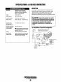
INSTALLATION
When installing WESTERBEKE engines and generators it is important that strict
attention be paid to the following information:
CODES AND REGULATIONS
Strict federal regulations, ABYC guidelines, and safety codes must be complied with
when installing engines and generators in a marine environment.
SIPHON-BREAK
For installations where the exhaust manifold/water injected exhaust elbow is close to
or will be below the vessel's waterline, provisions must be made to install a siphonbreak in the raw water supply hose to the exhaust elbow. This hose must be looped a
minimum of 20" above the vessel's waterline. Failure to use a siphon-break when
the exhaust manifold injection port is at or below the load waterline will result in
raw water damage to the engine and possible flooding of the boat.
If you have any doubt about the position of the water-injected exhaust elbow relative
to the vessel's waterline under the vessel's various operating conditions, install a
siphon-break.
NOTE: A siphon-break requires periodic inspection and cleaning to ensure proper
operation. Failure to properly maintain a siphon-break can result in catastrophic
engine damage. Consult the siphon-break manufacturer for proper maintenance.
EXHAUST SYSTEM
The exhaust hose must be certified for marine use. The system must be designed to
prevent water from entering the exhaust under any sea conditions and at any angle
of the vessels hull.
A detailed 40 page Marine Installation Manual covering gasoline and
diesel, engines and generators, is available from your WESTERBEKE
dealer.
Engines & Generators
iv
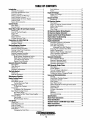
TABLE OF CONTENTS
Introduction ......................... '" .............................................2
Fuel Additives ............................................................. 17
Spares ......................................................................... 17
Engine Oil Change ............................................................ .18
Engine Oil Change ..................................................... 18
Oil Pressure ................................................................ 18
Remote Oil Filter ............................................................... 19
Installation .................................................................. 19
DC Electrical System .........................................................20
Description .................................................................20
Engine 12 Volt DC Control Circuit.. .......................... 20
Battery Specification .................................................. 20
Battery Care ............................................................... 20
Glow Plugs ................................................................. 20
DC Electrical System Wiring Diagram ..............................21
DC Electrical System Schematic ......................................22
Remote Control Panel Wiring Diagram ............................. 23
Warranty Procedures .................................................... 2
Customer Identification Card ....................................... 2
Product Software .......................................................... 2
Notes, Cautions and Warnings ..................................... 2
Serial Number Location ............................................... 3
Understanding the Diesel Engine ................................. 3
Ordering Parts .............................................................. 3
Spares and Accessories ............................................... .3
Control Panels .....................................................................4
Main Panel ................................................................... .4
Remote Panel. ...............................................................4
Diesel Fuel, Engine Oil and Engine Coolant.. .....................5
Diesel Fuel ................................................................... 5
Care Of The Fuel Supply ............................................ .5
Engine Oil .................................................................... 5
Oil Pressure .................................................................. 5
Engine Coolant ............................................................. 5
Coolant Recovery Tank ................................................ 5
Starter Motor Troubleshooting ......................................... 2~
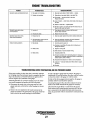
Engine Troubleshooting .....................................................26.
Engine Adjustments ..........................................................28
Preparations for Initial Start-Up .........................................6
Prestart Inspection ........................................................ 6
Generator Frequency Adjustment .............................. 28
Fuel Shutoff Solenoid ................................................28
Drive Belt Adjustment ................................................ 29
Adjusting Drive Belt Tension ............................. 29
Torquing The Cylinder Head Bolts ............................ 29
Engine Compression ................................................... 29
Injection Pump Timing Adjustment .......................... .30
Valve Clearance Adjustment ...................................... 31
Testing Fuel Injectors ................................................. 31
Generator Information .......................................................32
Use of Electric Motors .............................................. .32
Required Operatin,.g Speed ......................................... 32
Generator Troubleshooting ......................................... 32
Generator Maintenance .............................................. 32
BCD Generator Single Phase .............................................33
Description ................................................................. 33
Circuit Breaker .......................................................... .33
No-load Voltage Adjustment ..................................... .34
Integral Controller (I.C.) ........................................ ,... 35
Testing the Battery Charging Circuit ......................... 35
Generator Voltage ......................................................... 6
Starting/Stopping Procedure ..............................................7
The Starting System .....................................................7
Remote Starting Procedure .......................................... 7
Starting Under Cold Conditions ................................... 8
Stopping Procedure ....................................................... 8
Remote Stopping Procedure ......................................... 8
Safety Shut down Switches .......................................... 8
High Exhaust Temperature Switch ....................... 8
High Water Temperature Switch ........................... 8
Low Oil Pressure Switch ...................................... 8
Engine Circuit Breaker ......................................... 8
Generator Break-In Procedure ............................................9
Description ................................................................... 9
After Start-up ............................................................... 9
Check List .................................................................... 9
Generator Adjustments ................................................. 9
The Daily Routine ..............................................................10
Check List .................................................................. 10
Start the Generator ..................................................... 10
Maintenance Schedule ..................................................... 11
Engine Cooling Circuit ...................................................... 13
Description ................................................................. 13
Fresh Water Circuit .................................................... 14
Coolant Recovery Tank ....................................... 14
Changing Coolant. ...................................................... 14
To Refill the Coolant. .......................................... 14
Thermostat. ................................................................. 14
To Replace The Thermostat ................................ 14
Raw Water Cooling Circuit.. ...................................... 15
Raw Water Pump ................................................. 15
Changing the Raw Water Pump Impeller ........... 15
Heat Exchanger .......................................................... 15
Zinc Anode .......................................................... 15
Heat Exchanger Service ...................................... 15
Fuel System ....................................................................... 16
Diesel Fuel ................................................................. 16
Fuel Water Separator .................................................. 16
Fuel Lift Pump ........................................................... 16
Fuel Injection Pump ................................................... 16
Fuel Filters ................................................................. 17
Changing the Fuel Filter .................................... .17
~
Lay-up and Recommissioning ...........................................36
General ...................................................................... .36
Fresh Water Cooling System ...................................... 36
Lubrication System ................................................... .36
Fuel System ................................................................ 36
Raw Water Circuit ..................................................... .36
Intake Manifold and Through-hull Exhaust.. ............. 36
Generator End ............................................................ 37
Starter Motor .............................................................. 37
Cylinder Lubrication .................................................. 37
Spares ......................................................................... 37
Batteries ................................ :..................................... 37
Recommissioning ...................................................... .37
Specifications ....................................................................38
Shore Power Connections .................................................39
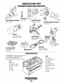
Parts Identification ...........................................................40
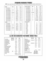
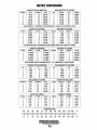
Standard Torques 4.0 KW BCD Torque Table ....................41
Metric Conversions ...........................................................42
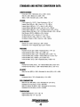
Suggested Spare Parts ......................................................44
WESTERBEKE
Engines & Generators
1
INTRODUCTION
PRODUCT SOFTWARE
This WESTERBEKE Diesel Generator is a product of
WESTERBEKE's long years of experience and advanced
technology. We take great pride in the superior durability and
dependable performance of our engines and generators.
Thank you for selecting WESTERBEKE.
Product software, (tech data, parts lists, manuals,
brochures and catalogs), provided from sources other than
WESTERBEKE are not within WESTERBEKE's control.
WESTERBEKE CANNOT BE RESPONSIBLE FOR THE
CONTENT OF SUCH SOFTWARE, MAKES NO WARRANTIES OR REPRESENTATIONS WITH RESPECT
THERETO, INCLUDING ACCURACY, TIMEliNESS OR
COMPLETENESS THEREOF AND WILL IN NO EVENT
BE liABLE FOR ANY TYPE OF DAMAGE OR INJURY
INCURRED IN CONNECTION WITH OR ARISING OUT
OF THE FURNISHING OR USE OF SUCH SOFTWARE.
In order to get the full use and benefit from your generator it
is important that you operate and maintain it correctly. This
manual is designed to help you do this. Please, read this
manual carefully and observe all the safety precautions
throughout. Should your generator require servicing, contact
your nearest WESTERBEKE dealer for assistance.
This is your operators manual. A parts catalog is also
provided and a technical manual is available from your
WESTERBEKE dealer. If you are planning to install this
equipment contact your WESTERBEKE dealer for
WESTERBEKE'S installation manual.
Your WESTERBEKE Warranty is included in a separate
folder. If, after 60 days of submitting the Warranty Registry
form you have not received a customer identification card
registering your warranty, please contact the factory in
writing with model information, including the unit's serial
number and commission date.
WESTERBEKE customers should keep in mind the time
span between printings ofWESTERBEKE product
software and the unavoidable existence of earlier
WESTERBEKE product software. The product software
provided with WESTERBEKE products, whether from
WESTERBEKE or other suppliers, must not and cannot
be relied upon exclusively as the definitive authority on
the respective product. It not only makes good sense
but is imperative that appropriate representatives of
WESTERBEKE or the supplier in question be consulted
to determine the accuracy and currentness of the
product software being consulted by the customer.
Customer Identification Card
NOTES, CAUTIONS AND WARNINGS
WARRANTY PROCEDURES
As this manual takes you through the operating procedures,
maintenance schedules, and troubleshooting of your marine
engine, critical information will be highlighted by NOTES,
CAUTIONS, and WARNINGS. An explanation follows:
'~/WESTERBEKE
I
Customer Identification
NOTE: An operating procedure essential to note.
MR. GENERATOR OWNER
MAIN STREET
A CAUTION: Procedures, which if not strictly
HOMETOWN, USA
Model 4.0 BCD
observed, can result in the damage Dr destruction of
your engine.
Ser. #UOOOO-D702
Expires 4/4/03
A WARNING: Procedures, wliich if not properly followed, can result in personal injury or loss of life.
Engines & Generators
2
INTRODUCTION
NOTE: A carbon monoxide warning decal has been provided
by WESTERBEKE. Affix this decal in a visible position in the
SERIAL NUMBER LOCATION
The engine and generator serial numbers and model numbers
are located on a decal on the generator housing. Take the
time to enter the information on the blank decal provided
below as this will provide a quick reference when seeking
technical information and/or ordering repair parts.
SPECIFICATION
50 HZ.
engine room.
UNDERSTANDING THE DIESEL ENGINE
The diesel engine closely resembles the gasoline engine,
since the mechanism is essentially the same. The cylinders
are arranged above a closed crankcase; the crankshaft is of
the same general type as that of a gasoline engine; and the
diesel engine has the same type of valves, camshaft, pistons,
connecting rods and lubricating system.
60 HZ.
MODEL _______ _
RPM __________ _
KW ___________ _
KVA __________ _
Therefore, to a great extent, a diesel engine requires the
same preventive maintenance as a gasoline engine. The
most important factors are proper ventilation and proper
maintenance of the fuel, lubricating and cooling systems.
Replacement of fuel and lubricating filter elements at the
time periods specified is a must, and frequent checking for
contamination (that is, water, sediment, etc.) in the fuel
system is also essential. Another important factor is the use
of the same brand of high detergent diesel lubrication oil
designed specificalJy for diesel engines.
VOLTS ________ _
AMPS ________ _
ENG. HP ______ _
ENG. SER. NO.
GEN. SER. NO.
PF/PHASE ___ _
WIRES ________ _
RATING _______ _
The diesel engine does differ from the gasoline engine,
however, in its method of handling and firing of fuel. The
carburetor and ignition systems are done away with and in
their place is a single component - the fuel injection pump
which performs the function of both.
I
ORDERING PARTS
INSUL CLASS __
TEMP. RISE ___ _
BAITERY _____ _
Whenever replacement parts are needed, always provide the
generator model number, engine serial number, and generator
serial number as they appear on the silver and black name
plate located on the generator end. You must provide us with
this information so we may properly identify your generator
set. In addition, include a complete part description and part
number for each part needed (see the separately furnished
Parts List). Also insist upon WESTERBEKE packaged parts
because will fit or generic parts are frequently not made to
the same specifications as original equipment.
C.I.D. _________ _
The engine serial number can also be found stamped into the
engine block just above the injection pump. The generator
serial number is stamped into the generator housing on the
flat surface on the left side of the generator.
SPARES AND ACCESSORIES
Certain spares will be needed to support and maintain your
WESTERBEKE generator. Your local WESTERBEKE
dealer will assist you in preparing an inventory of spare parts.
See the SPARE PARTS page in this manual. For Engine and
Generator Accessories, see the ACCESSORIES brochure.
An identification plate on the engine manifold also displays
the engine model and serial number.
GENERATOR
ID DECAL
SERIAL
NUMBER
Engines & Generators
3
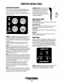
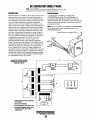
GENERATOR CONTROL PANELS
DESCRIPTION OF SWITCHES
EMERGENCY STOP: The EMERGENCY
This manually controlled series ofWESTERBEKE marine
diesel generators is equipped with toggle switches on the
engine control panel and, optionally, at remote panels.
stop switch on the rear of the control box
is normally closed. When depressed, it
will open the DC circuit to the control
panel and shut the engine down. As the
switch is not toggled it can be used when
performing maintenance.
All three switches are momentary contact type and serve the
following functions:
DESCRIPTION OF GAUGES
Coolant Temperature
Engine coolant (water) temperature should normally indicate
1750 to 1950 F (800 to 900 C).
Engine Oil Pressure
Oil pressure (psi) may fluctuate depending on the generator
load but should range between between 30 to 60 psi.
DC Voltmeter
Indicates the amount the battery is being charged should show
l3V to 14V.
Hourmeter
Registers elapsed time and is used as a guide for when to
perform scheduled maintenance.
PREHEAT: The PREHEAT toggle switch serves two purposes:
preheating the engine for easy starting and defeating of
bypassing the engine oil pressure switch. The defeat function
turns on the fuel solenoid, instrument power and alternator
excitation.
When the PREHEAT switch is depressed, the voltmeter,
panel lights, gauges and meters and fuel solenoid will
activate.
START: The START toggle switch closes the KI relay that
energizes the starter solenoid and activates the starter..
While the PREHEAT switch is still depressed, depressing the
START switch engages the start solenoid. When the engine
begins to fire, the START switch should be released. The
PREHEAT switch should not be released until the oil
pressure reaches 5 - 10 psi.
STOP: The STOP toggle switch is a normally closed switch.
providing power to the fuel solenoid, instrument cluster and
alternator excitation, after the oil pressure switch has closed
upon starting. Opening of this switch opens the power circuit
to the fuel solenoid, stopping the flow of fuel to the engine
and shuts down the engine.
To stop the engine, depress the STOP switch. When the
STOP switch is depressed, the power feed to the fuel
solenoid is opened, and the fuel flow to the engine is
stopped. The STOP switch should be depressed until the
generator stops rotating.
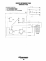
REMOTE PANEL
For remote operation of the generator system, the same three
switches are used. The PREHEAT and START switches are
connected in parallel with the gauge panel's switches and
serve the same functions as in the gauge panel. The STOP
switch is in series with the gauge panel's STOP switch and
serves the same function. There is a REMOTE START/STOP
WIRING DIAGRAM in this manual.
GENERATOR
til
RELEASE
STARTER
STOP
PREHEAT
START
MUST
PRESS
1ST
l~
.~~
\"'l
PRESS
2ND
==
WESTER8EKE
NOTE: For additional information on Control Panels. Refer to:
STARTING/STOPPING PROCEDURE, DC WIRING
DIAGRAMS and TROUBLESHOOTING GAUGES.
NOTE: When the engine is shut down, the water temperature
gauge and the oil pressure gauge will continue to register the
last temperature and oil pressure readings displayed. They
will return to zero once electrical power is restored.
Engines & Generators
4
DIESEL FUEL, ENGINE OIL AND ENGINE COOLANT
DIESEL FUEL
ENGINE COOLANT
Use fuel that meets the requirements or specification of Class
2-D (ASTM), and has a cetane rating of #45 or better.
WESTERBEKE recommends a mixture of 50% antifreeze
and 50% distilled water. Distilled water is free from the
chemicals that can corrode internal engine surfaces.
Care Of The Fuel Supply
The antifreeze performs double duty. It allows the engine to
run at proper temperatures by transferring heat away from the
engine to the coolant, and lubricates and protects the cooling
circuit from rust and corrosion. Look for a good quality
antifreeze that contains Supplemental Cooling Additives
(SCAs) that keep the antifreeze chemically balanced, crucial
to long term protection.
The distilled water and antifreeze should be premixed before
being poured into the cooling circuit.
Use only clean diesel fuel! The clearance of the components
in your fuel injection pump is very critical; invisible dirt particles which might pass through the filter can damage these
finely finished parts. It is important to buy clean fuel, and
keep it clean. The best fuel can be rendered unsatisfactory by
careless handling or improper storage facilities. To assure that
the fuel going into the tank for your engine's daily use is
clean and pure, the following practice is advisable:
Purchase a well-known brand of fuel.
Install and rcgularly service a good, visual-type fuel
filter/water separator between the fuel tank and the engine.
The RayeDI' 225 or 500MA are good examples of such filters.
NOTE: Lookfor the new environmentally-friendly long lasting
antifreeze that is now available.
Antifreeze mixtures will protect against an unexpected freeze
and they are beneficial to the engine's cooling system. They
retard rust and add to the life of the circulating pump seal.
ENGINE OIL
Use a heavy duty engine oil with an API classification of CF
or CG-4 or better. Change the engine oil after an initial 50
hours of break-in operation, and every 100 hours of operation
thereafter. For recommended oil viscosity, see the following
chart:
Operating Temperature
Oil Viscosity
Above 68°F (20°C)
SAE 30, 10W-30 or 15W-40
41° - 68°F (5 - 20°C)
SAE 20, 10W-30 or 15W-40
Below 41°F (5°C)
SAE 10W-30 or 15W-40
ANTIFREEZE PROTECTION
Antifreeze Concentration
Freezing Temperature
23%
30%
35%
50%
14°F
(-10°C)
8°F
(-13°C)
-4°F
(-20°C)
-40°F
(-40°C)
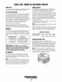
COOLANT RECOVERY TANK
A coolant recovery tank kit is supplied with each
WESTERBEKE diesel engine. The purpose of this recovery
tank is to allow for engine coolant expansion and contraction
during engine operation, without the loss of coolant and
without introducing air into the cooling system. This kit is
provided and must be installed before operating the engine.
A CAUTION: Do not allow two or more brands of
engine oil to mix. Each brand contains its own additives;
additives of different brands could react in the mixture
to produce properties harmful to your engine.
NOTE: This tank, with its short run of plastic hose, is best
located at or above the level of the engine's manifold, but it
can be located below the level of the engine's manifold if the
particular installation makes this necessary.
OIL PRESSURE
The engine's oil pressure, during operation, is indicated
by the oil pressure gauge on the instrument panel. During
normal operation, the oil pressure will range between 35 and
55 psi (2.5 and 3.9 kg/cm2).
NOTE: A newly started, cold engine can have an oil pressure
reading up to 60 psi (4.2 kg!cm2). A warmed engine can have
an oil pressure reading as low as 25 psi (1.8 kg!cm2). These
readings will vary depending upon the temperature of the
engine, the load placed on the engine, and the RPM's.
\
\
",'-
Engines & Generators
5
PREPARATIONS FOR INITIAL START-UP
PRESTARTINSPECTION
A CAUTION: When starting the generator, it is
This section of the manual provides the operator with preparation, initial starting, break-in, starting (warm or cold) and
stopping procedures. Follow the procedures as presented for
the conditions indicated and your WESTERBEKE generator
set will give reliable performance and long service life.
recommended that al/ AC loads, especially large motors,
be switched OFF until the engine has come up to speed
and, in cold Climates, starts to warm up. This precaution
will prevent damage caused by unanticipated operation
of the AC machinery and will prevent a cold engine from
stalling.
Before starting your generator set for the first time or after a
prolonged layoff, check the following items:
D Check the engine oil level. Add oil to maintain the level at
the high mark on the dipstick.
GENERATOR VOLTAGE
D Check the fuel supply and examine the fuel filter/separator
The speed of the genera.tor engine is adjusted at the factory,
however, it is advisable to verify.
bowls for contaminants.
D Check the DC electrical system. Inspect wire connections
To supply 60 Hertz, the speed should be 1800 RPM at no load,
and should not fall below 1800 RPM by more than 5 percent
(3 Hz) at full load.
Generator voltage should build to its rated value within
5 seconds after rated speed is attained. Record or observe voltage of generator at no load and at full load (hot). The voltages
are easily adjusted to optimum values no load and full load
(refer to VOLTAGE ADJUSTMENT in this manual). If possible,
apply actual service load or test load of the same power factor
as the load to be used in service. If voltage cannot be adjusted
to suitable values and some fault seems evident, contact your
authorized WESTERBEKE service dealer.
and battery cable connections.
D Check the coolant level in both the plastic recovery tank
and at the manifold.
D Visually examine the unit. Look for loose or missing
parts, disconnected wires, unattached hoses, and check
threaded connections.
D Check load leads for correct connection as specified in the
wiring diagrams.
D Examine air inlet and outlet for air flow obstructions.
D Be sure no other generator or utility power is connected to
load lines.
D Be sure that in power systems with a neutral line that
the neutral is properly grounded (or ungrounded) as the
system requires, and that the generator neutral is properly
connected to the load neutral. In single phase and some
3-phase systems an incomplete or open neutral can supply.
the wrong line-to-neutral voltage on unbalanced loads.
D Make sure the mounting installation is secure.
D Make sure that the generator is properly grounded.
OIL FILL CAP
COOLANT
RECOVERY
TANK
TO NIPPLE AT
MANIFOLD PRESSURE CAP
OIL DIPSTICK
/MAX
LOW
Engines & Generators
6
STARTING/STOPPING PROCEDURE
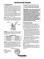
THE STARTING SYSTEM
Should the engine not start when the START switch is
depressed for 10 to 20 seconds, release both switches and
wait 30 seconds; repeat the procedure above and preheat
longer. Never run the starter for more than 30 seconds.
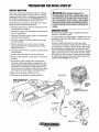
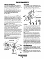
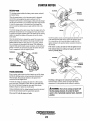
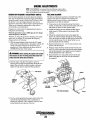
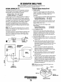
Westerbeke diesel generators use electric starters assisted by
glow plugs for both normal and cold weather starting. The
illustration below shows a cross-sectional view of one cylinder. The glow plug is located in the combustion chamber so
that its tip is in the injector nozzle's spray path. When the
glow plug is energized by the PREHEAT button, the plug
glows red at the tip and assists in igniting the fuel. The result
is a rapid start with less wear on the starter.
A CAUTION: Prolonged cranking intervals without the
engine starling can result in the engine exhaust system
filling with raw water. This may happen because the
pump is pumping raw water through the raw water cooling system during cranking. This raw water can enter the
engine's cylinders by way of the exhaust manifold once
the exhaust system fills. Prevent this from happening by
closing the raw water supply through-hull shut-off,
draining the exhaust muffler, and co"ecting the cause
of the excessive engine cranking. Engine ,damage resulting from raw water entry is not a warrantable issue; the
owner/operator should keep this in mind.
This system is common to WESTERBEKE diesels. The start
circuitry is designed so that the PREHEAT button must be
depressed for the time specified in the preheat chart. Then,
while keeping the PREHEAT button engaged, the START
button is depressed to crank the engine.
NOTE: The START switch will not energize unless the PREHEAT switch is depressed. Depressing the PREHEAT switch
activates the glow plugs in the cylinder head so use the PREHEAT intermittently to avoid overheating the glow plugs.
GLOW PLUG
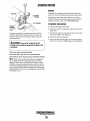
Remote Starting Procedure
The remote start panel is the same as the engine-mounted
start panel except that it has a green LED light and no
gauges. When starting at a remote location, the green LED
lights when the generator is running at approximately 600
rpm. This indicates when the START switch can be released
since the starting of the generator may not be audible.
A When the PREHEAT switch is depressed at the remote
start/stop panel the LED light will illuminate. When the
START switch is depressed and the starter cranks the
engine this LED light will dim. When the engine starts the
LED light will brighten signaling to release the START
switch. Continue to hold the PREHEAT depressed for a
few seconds to allow oil pressure to build up which closes
the oil pressure safety switch that is in the series path for
12V B+ to the fuel run solenoid.
PREHEAT: Depress the PREHEAT switch. The voltmeter and
panel lights, gauges and meters will be activated. The PREHEAT switch should be depressed in accordance with the
following chart:
Temperature/Preheat
Atmospheric Temperature
Preheating Time
+41°F(+5°C) or higher
Approx. 10 seconds
+41°F(+5°C) to 23°F (-5°C)
Approx. 15 seconds
B. After the generator is started and the START switch is
+23°F(-5°C) or lower
Approx. 20 seconds
Limit of continuous use
30 seconds before cranking
released, the generator's starter will not crank unless the
PREHEAT switch is operated first because this switch
supplies voltage to the START switch.
Once the engine starts, check the engine's instruments for
proper oil pressure and battery charging voltage. Apply a
light load to the generator and allow the engine's operating
temperature tq come up to 140-150° (60-66° C) before
applying heavy loads.
START: While still depressing the PREHEAT switch, depress
the START switch. This will engage the starter solenoid.
Upon engine starting, release the START switch. Do not
release the PREHEAT switch until the oil pressure reaches
15 psi. Then as long as the high water temperature and low
oil pressure protective circuits do not activate, the engine will
remain energized and continue to run.
NOTE: Some unstable running may occur in a cold engine.
Depressing the PREHEAT switch for 10-15 second intervals
will help stabilize the engine RPM until the operating
temperature reaches the 140 -150° F and a load is applied
to the engine.
NOTE: When starting:
A voltage drop will occur
when the preheat switch
is depressed.
Engines & Generators
7
STARTING/STOPPING PROCEDURE
STARTING UNDER COLD CONDITIONS
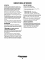
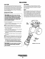
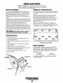
High Water Temperature Switch
Make sure the lubricating oil conforms with the ratings for
the prevailing temperature. Check the table in the ENGINE
OIL section in this manual.
A high water temperature switch is located on the thermostat
housing. Normally closed, this switch, should the fresh water
coolant's operating temperature reach approximately 210°F
(99°C), will open and interrupt the DC voltage to the fuel
solenoid on the injection pump, thereby shutting off the
engine. This switch resets at 195°P (107°C).
The battery should be fully charged to minimize voltage
drop.
Use a sufficient amount of preheat to aid in starting. See the
Temperature/Preheat chart elsewhere in this section.
STOPPING PROCEDURE
WATER
TEMPERATURE
SWITCH
'
1. Remove the AC electrical load from the generator and
allow the generator to run for three to five minutes to stabilize its operating temperatures.
,--T
~
2. Depress the STOP switch and hold it until the generator is
completely stopped.
WATER
TEMPERATURE
SENDER
3. Now release the STOP switch.
Remote Stopping Procedure
To stop the generator, depress the STOP switch which opens
the normally closed B+ path for voltage to the engine's run
circuit. The STOP switch must be held open until the generator comes to a complete stop.
Low Oil Pressure Switch
SAFETY SHUTDOWN SWITCHES
A low oil pressure shutdown switch is located off the
engine's oil gallery. Normally open in a static state, this
switch's sensor monitors the engine's oil pressure. Should the
engine's oil pressure fall to 5-10 psi, this switch will open
interrupting the DC voltage to the fuel solenoid on the injection pump, thereby shutting off the engine.
The engine is protected- by three automatic shutdown
switches. Should shutdown occur, do not attempt to restart
without finding and correcting the cause. Refer to the
heading "Engine Stops" in the TROUBLESHOOTING
section of this manual.
The following is a description of these automatic shutdown
switches:
High Exhaust Temperature Switch
An exhaust temperature switch is located on the exhaust
elbow. Normally closed, this switch will open and interrupt
the DC voltage to the fuel solenoid on the injection pump
(shutting OFF the engine) should the switch's sensor indicate
an excessive exhaust temperature (an inadequate supply of
raw water causes high exhaust temperatures). This switch
opens at 260-270°F (127-132°C). This switch resets at
approximately 225°F (107°C).
OIL
JRESSURE
SENDER
OIL
PRESSURE
SWITCH
Engine Circuit Breaker
The generator's engine is protected by an engine mounted
manual reset circuit breaker (20 amps DC). Excessive current
draw or electrical overload anywhere in the instrument panel
wiring or engine wiring will cause the breaker to trip. In this
event most generators will shut down because the opened
breaker disconnects the fuel supply. If this should occur,
check and repair the source of the problem. After repairing
the fault, reset the breaker and restart the generator.
EXHAUST
TEMPERATURE
SWITCH
Engines & Generators
8
GENERATOR BREAK-IN PROCEDURE
DESCRIPTION
CHECK THE FOLLOWING
Although your engine has experienced a minimum of one
hour of test operations at the factory to make sure accurate
assembly procedures were followed and that the engine
operated properly, a break-in time is required. The service
life of your engine is dependent upon how the engine is
operated and serviced during its initial hours of use.
D Monitor the control panel gauges.
D Check for leaks of fuel and engine oil.
D Check for abnormal noise such as knocking, friction,
vibration and blow-back sounds.
D Confirm exhaust smoke:
Breaking-in a new engine basically involves seating the
piston rings to the cylinder walls. Excessive oil consumption
and smoky operation indicate that the cylinder walls are
scored, which is caused by overloading the generator during
the break-in period.
When the engine is cold - White Smoke.
When the engine is warm - almost Smokeless.
When the engine is overloaded - some Black Smoke.
To protect against unintentional overloading of the generator,
the generator's output leads should be routed through a circuit
breaker that is rated at the rated output of the generator.
Your new engine requires approximately 50 hours of initial
conditioning operation to break in each moving part in order
to maximize the performance and service life of the engine.
Perform this conditioning carefully, keeping in mind the
following:
NOTE: Be aware of motor starting loads and the high current
draw required for starting motors. This starting amperage
draw can be 3 to 5 times normal running amperage. See
GENERATOR INFORMATION in this manual.
Start the engine according to the STARTING PROCEDURE
section. Run the engine while checking that all systems (raw
water pump, oil pressure, battery charging) are functioning.
GENERATOR ADJUSTMENTS
Once the generator has been placed in operation, there may
be adjustments required for engine speed (hertz) during the
engine's break-in period (first 50 hours) or after this period.
A no-load voltage adjustment may also be required in
conjunction with the engine's speed adjustment. See
GENERATOR INFORMATION in this manual.
AFTER START-UP
Once the generator has been started, check for proper
operation and then encourage a fast warm-up. Run the generator between 20% and 60% of full load for the first 10 hours.
A
CAUTION: 00 not attempt to break-in your
generator by running without a load.
After the first 10 hours of the generator's operation, the load
can be increased to the full-load rated output, then periodically vary the load.
Avoid overload at all times. An overload is signaled by
smoky exhaust with reduced output voltage and frequency.
Monitor the current being drawn from the generator and keep
it within the generator's rating. Since the generator operates
at 1800 RPM to produce 60 hertz, control of the generator's
break-in is governed by the current drawn from the generator.
Engines & Generators
9
THE DAILY ROUTINE
CHECK LIST
START THE GENERATOR
Each day before starting your generator, take a few moments
to run this check list:
(See STARTING PROCEDURES on previous pages).
Allow the engine to wam1 up for 5 to 10 minutes to reach
operating temperatures of 140° to 150°F (60°-66°C) before
applying AC loads, apply loads systematically allowing the
generator to adjust to each load before applying the next.
Check the gauges for proper oil pressure, operating temperature, and DC voltage.
o Record the hourmeter reading in your log (engine hours
relate to the maintenance schedule.)
o Visually inspect the generator for fuel, oil, or water leaks.
o Check the oil level (dipstick).
o Check the coolant level in the coolant recovery tank.
NOTE: Some unstable running may occur in a cold engine.
This condition should abate as normal operating temperature
is reached and loads are applied.
o Check your diesel fuel supply.
o Look for clean fuel in the fuel/separator transparent bowl.
o Check for loose wires at the alternator.
A CAUTION: Do not operate the generator for long
periods of time without a load being placed on the
generator.
o Check the starting batteries (weekly).
o Check drive belts for wear and proper tension (weekly).
STOPPING THE GENERATOR
Remove the major AC loads from the generator one at a
time. Allow the generator to run for a few minutes to stabilize the operating temperature and depress the stop switch.
(See STOPPING PROCEDURES on previous pages.)
Engines & Generators
10
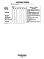
MAINTENANCE SCHEDULE
2.
A WARNING: Never attempt to perform any service while the engine is
running. Wear the proper safety equipment such as goggles and gloves, and
use the correct tools for each job. Disconnect the battery terminals when
servicing any of the engine's DC electrical equipment.
NOTE: Many of the following maintenance jobs are simple but others are more
difficult and may require the expert knowledge of a service mechanic.
SCHEDULED
MAINTENANCE
Fuel Supply
CHECK
EACH
DAY
EXPLANATION OF SCHEDULED
MAINTENANCE
HOURS OF OPERATION
50
100
250
500
750 1000 1250
Diesel No.2 rating of 45 cetane or higher.
Fuel/Water Separator
0
0
Engine Oil level
0
Oil level should indicate between MAX. and LOW on
dipstick.
Coolant Level
0
Check at recovery tank; if empty, check at manifold.
Add coolant if needed.
0
Inspect for proper tension (3/8" to 1/2" depression)
and adjust if needed. Check belt edges for wear.
Drive Belts
Check for water and dirt in fuel (drain/replace 'filter
if necessary).
weekly
Visual Inspection of Engine
0
Fuel Filter
Starling Batteries
(and House Batteries)
NOTE: Please keep engine surface clean. Dirt
and oN will inhibit the engine's ability to
remain cool.
0
0
0
0
Generator
D
0
0
0
D
Heat Exchanger Zinc Anode
D
0
D
D
0
D
0
0
D
D
Fuel/Water Separator
Raw Water Pump
Coolant System
Fuel Injectors
Initial change at 50 hrs., then change every 250 hrs.
Every 50 operating hours, check electrolyte levels
and make sure connections are very tight. Clean off
excessive corrosion.
0
0
Engine Hoses
0
weekly
Engine Oil (and filter)
Exhaust System
0
Check for fuel, oil and water leaks. Inspect wiring
and electrical connections. Keep bolts & nuts tight.
Check for loose belt tension.
0
Change initial engine oil and filter at 50 hours, then
change both every 100 hours.
D
0
Check that AC connections are clean and secure
with no chafing. See GENERATOR MAINTENANCE
for additional information.
D
0
D
Inspect zinc anode, replace if needed, clear the heat
exchanger end of zinc anode debris.
0
0
D
D
D
Change every 200 hours.
D
D
0
Hose should be hard & tight. Replace if soft or
spongy. Check and tighten all hose clamps.
NOTE: At 800 operating hours
disassemble and inspect for
overhaul.
D
Remove the pump cover and inspect impeller, cam
and cover for wear. Clleck the shaft bearings and
seals (shaft Sllould not wobble). Lubricate when
reassembling.
0
0
Drain, flush, and refill cooling system with
appropriate antifreeze mix.
0
D
D
D
0
Engines & Generators
11
Initial check at 50 hours, then every 250 hours.
Inspect for leaks. Check anti-siphon valve
operation. Check the exhaust elbow for carbon
and/or corrosion buildup on inside passages;
clean and replace as necessary. Check that all
connections are tight.
Check and adjust injection opening pressure and
spray condition (see ENGINE ADJUSTMENTS).
MAINTENANCE SCHEDULE
NOTE: Use the engine hour meter gauge to log your engine hours or record your
engine hours by running time.
SCHEDULED
MAINTENANCE
CHECK
EACH
DAY
HOURS OF OPERATION
50
100
250
500
750 1000 1250
EXPLANATION OF SCHEDULED
MAINTENANCE
*Starter Motor
0
0
Check solenoid and motor for corrosion. Remove
and lubricate. Clean and lubricate the starter motor
pinion drive.
*Preheat Circuit
D
0
Check operation of preheat solenoid. Remove and
clean glow plugs; check resistance (4-6 ohms).
Reinstall with anti seize compound on threads.
*Engine Cylinder
Compression
0
D
Check compression pressure and timing (see Engine
Adjustments) .
*Torque Cylinder Head
Hold-down bolts
D
0
0
At first 50 hours, then every 500 hours (see
ENGINE ADJUSTMENTS).
*Adjust the Valve Clearances
D
D
D
Adjust Valve Clearances (see ENGINE
ADJUSTMENTS).
0
Remove, have professionally cleaned and pressure
tested.
*Heat Exchanger
*WESTERBEKE recommends this service be performed by an authorized mechanic.
Engines & Generators
12
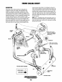
ENGINE COOLING CIRCUIT
DESCRIPTION
Westerbeke marine diesel generators are designed and
equipped for fresh water cooling. Heat produced in the
engine by combustion and friction is transferred to fresh
water coolant which circulates throughout the engine. This
circulating fresh water coolant cools the engine block and its
internal moving parts. The heat is transferred externally from
the fresh water coolant to raw water by means of a heat
exchanger; similar in function to an automotive radiator. Raw
water flows through the tubes of the heat exchanger while
fresh water coolant flows around the tubes; engine heat trans- ,
ferred to the fresh water coolant is conducted through the
tube walls to the raw water which is then pumped into the
/---........
.•
~
'~
exhaust system where finally it is discharged overboard. In
other words, the engine is cooled by fresh water coolant, this
coolant is cooled by raw water, and the raw water carries the
transferred heat overboard through the exhaust system. The
fresh water coolant and raw water circuits are independent of
each other. Using only fresh water coolant within the engine
allows the cooling water passages to stay clean and free from
harmful deposits.
NOTE: Refer to ENGINE COOLANT paragraphs in this section for the recommended antifreeze and water mixture to be
used as the fresh water coolant and for information on filling
the fresh water system.
------------NOTE: KEEP PASSAGE
THROUGH THE MANIFOLD
CLEAR (A PIPE CLEANER
WORKS WELL).
EXHAUST
,
~ NOTE: AN ANTI-SIPHON
- "-, VALVE MAY BE REQUIRED
\
.~.
',;
{}:
COOLING CIRCUIT DIAGRAM
FRESH WATER
RAWWATER
¢
FRESH WATER
DRAIN
~
RAW WATER DRAIN
Engines & Generators
13
ENGINE COOLING CIRCUIT
Fresh Water Circuit
After checking for leaks, stop the engine and allow it to cool.
Coolant should draw back into the cooling system as the
engine cools down. Add coolant to the recovery tank if
needed. Clean up any spilled coolant.
Fresh water coolant is pumped through the engine by a beItdriven circulating pump, absorbing heat from the engine. The
fresh water coolant circulates through the engine's block
absorbing heat, then passes through the thermostat into the
exhaust manifold, to the heat exchanger where it is cooled,
and then is returned to the engine block through the suction
side of the fresh water circulating pump. When the engine is
started cold, external coolant flow is prevented by the closed
thermostat (although some coolant flow is bypassed around
the thermostat to prevent the exhaust manifold from overheating). As the engine warms up, the thermostat gradually
opens, allowing full flow of the engine's coolant to flow
unrestricted to the external portion of the cooling system.
NOTE: Periodically check the condition of the manifold pressure cap. Ensure that the upper and lower rubber seals are in
good condition and check that the vacuum valve opens and
closes tightly. Carry a spare cap. Use a pipe cleaner to keep
the passageway clear from the jiller cap to the recovery tank
hose.
THERMOSTAT
A coolant recovery tank allows for engine coolant expansion
and contraction during engine operation, without any significant loss of coolant and without introducing air into the cooling system. This tank should be located at or above the
engine manifold level and should be easily accessible.
A thermostat, located near the manifold at the front of the
engine, controls the coolant temperature, as it continuously
flows through the closed cooling circuit. When the engine
is first started the closed thermostat prevents coolant from
flowing (some coolant is by-passed through a hole in the
thermostat to prevent the exhaust manifold from overheating), as the engine warms up the thermostat gradually opens.
The thermostat is accessible and can be checked, cleaned, or
replaced easily. Carry a spare thermostat and gasket.
CHANGING COOLANT
To RepJace the Thermostat
The engine's coolant must be changed according to the
MAINTENANCE SCHEDULE. If the coolant is allowed to
become contaminated, it can lead to overheating problems.
Remove the two cap screws and disassemble the thermostat
housing as shown. When installing the new thennostat and
gasket apply a thin coat of sealant on both sides of the gasket
before pressing it into place. Do NOT over-tighten the cap
screws.
Run the engine and check for nonnal temperatures and that
there are no leaks at the thermostat housing.
Coolant Recovery Tank
A CAUTION: Proper cooling system maintenance is
critical; a substantial number of engine failures can be
traced back to cooling system corrosion.
Drain the engine cool~t by removing the drain plug under
the manifold and opening the manifold pressure cap. Flush
the system with fresh water, then start the refill process.
WATER
TEMPERATURE
SWITCH
NOTE: The drain plug on the heat exchanger can also be used
to drain engine coolant.
A WARNING: Beware of the hot engine coolant.
Wear protective gloves.
To Refill With Coolant
After replacing the manifold drain plug, run the engine at
idle and slowly pour clean, premixed coolant into the manifold.
NOTE: When a steady flow of coolant appears at the heat
exchanger drain plug opening, close the drain plug and jill
the system until the manifold remains full.
WATER
TEMPERATURE·
SENDER
Monitor the coolant in the manifold and add as needed. Fill
the manifold to the filler neck and install the manifold pressure cap.
Remove the cap on the coolant recovery tank and fill with
coolant mix to halfway between LOW and MAX and replace
the cap. Run the engine and observe the coolant expansion
flow into the recovery tank.
CHANGING THE THERMOSTAT
Engines & Generators
14
ENGINE COOLING CIRCUIT
RAW WATER COOLING CIRCUIT
Heat Exchanger
The raw water flow is created by a positive displacement
impeller pump. This pump draws water directly from the
ocean, lake, or river through a hose to the water strainer. The
raw water passes from the strainer through the heat
exchanger (through the heat exchanger tubes) where it cools
the engine circulating fresh water coolant. The raw water is
then discharged into the water injected exhaust elbow, mixing with and cooling the exhaust gass~s. This mixture of
exhaust gas and raw water is pushed overboard.
The heat exchanger is a copper tube which encloses a number of small copper tubes. Raw water is pumped through the
small copper tubes and the freshwater coolant from the
engine is circulated around the copper tubes. The raw water
removes heat from the freshwater coolant.
Raw Water Pump
GASKET
The raw water pump is a self-priming, rotary pump with a
non-ferrous housing and a neoprene impeller. The impeller
has flexible vanes which wipe against a curved cam plate
within the impeller housing, producing the pumping action.
On no account should this pump be run dry as water acts as a
lubricant for the impeller. There should always be a spare
impeller and impeller cover gasket aboard (an impeller kit).
Raw water pump impeller failures occur when lubricant (raw
water) is not present during engine operation. Such failures
are not warrantable, and operators are cautioned to make sure
raw water flow is present at start-up.
OUT DEBRIS
=---RAWWATER DRAIN
CLEAN
BAD
NOTE: Should a failure ~occur with the p~p:S internal parts
(seals and bearings) it may be more cost efficient to purchase
a new pump and rebuild the original pump as a spare.
AND
REUSE
Zinc Anode
A zinc anode, or pencil, is located in the raw water cooling
circuit within the heat exchanger. The purpose of the zinc
anode is to sacrifice itself to electrolysis action taking place
in the raw water cooling circuit, thereby reducing the effects
of electrolysis on other components of the system. The condition of the zinc anode should be checked monthly and the
anode cleaned or replaced as required. Spare anodes should
be carried on board.
Changing the Raw Water Pump Impeller
Close the raw water intake valve. Remove the impeller with
the aid of two small screwdrivers, as illustrated, and carefully
pry the impeller out of the pump. Install the new impeller
and gasket by positioning the hub pin to align with the slot in
the drive shaft. Mo~e the blades to conform to the curved
cam plate and push the impeller into the pump's housing.
When assembling, apply a thin coating of lubricant to the
impeller and gasket. Open the raw water intake valve before
starting the engine.
NOTE: Electrolysis action is the result of each particular
installation and vessel location; not that of the generator.
If the.zinc pencil needs replacement, hold the hex boss into
which the zinc pencil is threaded with a wrench while loosening the anode with another wrench. This prevents the hex
boss from possibly tearing off the exchanger shell. After
removing the zinc, note the condition of it. If the zinc is in
poor condition, there are probably a lot of zinc flakes within
the exchanger. Remove the end of the heat exchanger and
clean the inside of all zinc debris. Always have a spare heat
exchanger end gasket in case the present one becomes damaged when removing the end cover. Replace the gasket (refer
to your engine model's heat exchanger end gasket part number), o-ring, cover, and install a new zinc pencil.
NOTE: If any of the vanes have broken off the impeller they
must be found to prevent blockage in the cooling circuit.
They often can be found in the heat exchanger. ,
RAW WATER PUMP
IMPELLER
Heat Exchanger Service
GASKET
After approximately 1000 hours of operation, remove, clean
and pressure test the engine's heat exchanger. (A local automotive radiator shop should be able to clean and test the heat
exchanger. )
NOTE: Operating in silty and/or tropical waters may require
tht;lt a heat exchanger cleaning be performed more often than
every 1000 hours.
Engines & Generators
15
FUEL SYSTEM
DIESEL FUEL
FUEL INJECTION PUMP
Use No.2 diesel fuel with a cetane rating of 45 or higher. Do
not use kerosene or home heating fuel.
The fuel injection pump is the most important component of
the diesel engine and, therefore, calls for the utmost caution
in handling. The fuel injection pump has been thoroughly
bench-tested and should not be tampered with.
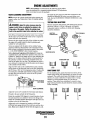
FUEL WATER SEPARATOR
A primary fuel filter of the water separating type must be
installed between the fuel tank and the engine to remove
water and other contaminants from the fuel before they can
be carried to the fuel system on the el,1gine.
Speed (hertz) and timing are the only adjustments the
servicing dealer can perform on the injection pump. See the
ENGINE ADJUSTMENT section in this manual. Other types
of adjustments or repairs must be performed by a qualified
injection service shop.
Most installers include a filter/water separator with the installation package as they are aware of the problems that contaminants in the fuel can cause.
A typical fuel filter/water separator is illustrated in this
diagram. This is the Raycor Model 500 MA. Keep in mind
that if a water separator type filter is not installed between the
fuel supply tank and engine-mounted fuel system, any water
in the fuel will affect the fuel pump, engine filter, and injection equipment. The owner/operator is responsible for making
certain the fuel reaching the engine's injection equipment is
free of impurities. This process is accomplished by installing
and maintaining a proper filtration/separation system.
NOTE: When servicing the injection pump, the service shop
must be advised that the pump is,being used in a generator
application.
)
TYPICAL FUEL
FILTER/WATER
SEPARATOR
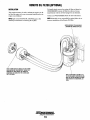
FUEL LIFT PUMP
Periodically check the fuel connections to and out of the pump
and make sure that no leakage is present and that the fittings
are tight and secure. The DC ground connection at one of the
pump's mounting bolts should be clean and well secured by
the mounting bolt to ensure proper pump operation.
A WARNING: Fuel leakage at the fuel pump or its
connections is a fire hazard and should be corrected.
Make sure proper ventilation exists whenever serVicing
fuel system components.
t
\
FUEL FILTER
FUEL SYSTEM
INTO DC WIRING
FUEL LIFT PUMP
Engines & Generators
16
"
FROM FUEL FILTER!
WATER SEPARATOR
FUEL SYSTEM
FUEL FILTERS
Fuel Additives
The fuel injection pump and the fuel injectors are precisely
manufactured and they must receive clean diesel fuel, free
from water and dirt. To ensure this flow of clean fuel, the fuel
must pass through at least two fuel filters, a fuel water separator and the engine's spin-on fuel filter. Visually inspect,
clean, and change these filters according to the maintenance
schedule in this manual.
If fungus or bacteria is causing fuel problems you should
have an authorized dealer correct these problems. Then use a
diesel fuel biocide to sterilize the fuel (follow the manufacturers instructions).
Spares
While the likelihood of having to service the system at sea is
slim, the possibility does exist. Therefore, we recommend
that banjo washers, injector seat washers, and a fuel filter be
carried on board at all times. Purchase needed spares from
your local WESTERBEKE dealer or distributor. If a leak
should develop at a banjo washer that cannot be corrected by
a simple tightening of the fitting, replace the sealing washer
with a replacement found in the hardware kit for your model.
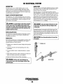
Changing the Fuel Filter
A
WARNING: Shut off the fuel valve at the tank
when servicing the fuel system. Take carein catching
any fuel that may spill. DO NOT allow any smoking,
open flames or other sources of fire near the fuel system when servicing. Ensure proper ventilation exists
when servicing the fuel system.
1. Shut the fuel supply off.
2. Remove the fuel filter retaining ring by turning it counter
clockwise and discard the filter element.
NOTE: This element contains fuel. Take care not to spill it
during disassembly and discard the used element properly.
. 3. Wipe clean the sealing face on the housing so the new
filter will seat properly.
4. Lightly oil the sealing o-rings on the new filter and assemble the element and its retaining ring.
S. Tum on the fuel and start the engine. The normal preheat
function should quickly prime the system and the engine
should start.
6. Wipe down the fuel filter assembly to make certain there
are no leaks.
NOTE: When using the preheat function to bleed air from the
filter assembly, keep in mind that the preheat elements (glow
plugs) are being energized. Take care not to overheat them.
O-RING
LIGHTLY OIL ON
REASSEMBLY
7. Should the engine fail to start when the start switch is
depressed for 10 or 20 seconds, release and wait 30 seconds. Repeat the procedure and preheat for a longer
period. Never run the starter for more than 30 seconds.
FILTER
ELEMENT
A
WARNING: Do not allow smoking or open flames
near the fuel system when servicing. Also provide
proper ventilation.
CHANGING THE FUEL FILTER
I
"
Engines & Generators
17
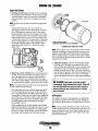
ENGINE OIL CHANGE
Engine Oil Change
1. Draining the Oil Sump. Discharge the used oil through
the sump drain hose (attached to the front of the engine)
while the engine is warm. Drain the used oil completely,
replace the hose in its bracket, and replace the end cap
securely.
OIL FILTER
NOTE: Thread size for the lube oil drain hose capped end is
1/4NPT.
Always observe the used oil as it is removed. A
yellow/gray emulsion indicates the presence of water in
the oil. Although this condition is rare, it does require
prompt attention to prevent serious damage. Call a competent mechanic should water be present in the oil. Raw
water present in the oil can be the result of a fault in the
exhaust system attached to the engine and/or a siphoning
of raw water through the raw water cooling circuit into
the exhaust, fiIIing the engine. This problem is often
caused by the poor location of or the lack of an antisiphon valve.
CHANGING THE ENGINE OIL FILTER
NOTE: Generic filters are not recommended, as the material
standards or diameters of important items on generic parts
might be entirely different from genuine parts. Immediately
after an oil filter change and oil fill, run the engine to make
sure the oil pressure is normal and that there are no ai/leaks
around the new oil filter.
OIL
DRAIN
HOSE
3. Filling the Oil Sump. Add new oil through the oil filler
cap on the top of the engine or through the side oil fill.
After refilling, run the generator for a few moments while
checking the engine's oil pressure. Make sure there is no
leakage around the new oil filter or from the oil drain system, and stop the generator. Then check the quantity of oil
with the lube oil dipstick. Fill to, but not over the high
mark on the dipstick, should the engine require additional
oiL
2. Replacement of the Oil Filter. When removing the us~d
oil filter, you may find it helpful and cleaner to punch a
hole in the upper and lower portion of the old filter to
drain the oil from it into a container before removing it.
This helps to lessen spillage. A small style automotive filter wrench should be helpful in removing the old oil filter.
A
WARNING: Used engine oil contains harmful
contaminants. Avoid prolonged skin contact. Clean skin
and nails thoroughly using soap and water. Launder or
discard clothing or rags containing used oil. Discard
used oil properly.
NOTE: Do not punch this hole without first loosening the filter
to make certain it can be removed!
Place some paper towels and a plastic bag around the filter when unscrewing it to catch any oil left in the filter.
(Oil or any other fluid on the engine reduces the engine's
cooling ability. Please keep your engine clean.) Inspect the
old oil filter as it is removed to make sure that the rubber
sealing gasket came off with the old oil filter. If this rubber sealing gasket remains sealed against the engine
block, gently remove it.
Oil Pressure
The engine's oil pressure, during operation, is indicated by
the oil pressure gauge on the instrument panel. During normal operation, the oil pressure will range between 35 and 55
psi.
When installing the new oil filter element, wipe the filter
gasket's sealing surface on the engine block free of oil and
apply a thin coat of clean engine oil to the rubber gasket
on the new oil filter. Screw the filter onto the threaded oil
filter nipple, and then tighten the filter firmly ?y hand.
NOTE: A newly started, cold engine can have an oil pressure
reading upwards of 60 psi. A warmed engine can have an oil
pressure reading as low as 35 psi. These readings will vary
depending upon the temperature of the engine and the load
placed on the generator.
Engines & Generators
18
REMOTE OIL FILTER (OPTIONAL)
INSTALLATION
To install, simply remove the engine oil filter and thread on
WESTERBEKE's remote oil filter kit as shown. Always
install this kit with the oil filter facing down as illustrated.
This popular accessory is used to relocate the engine's oil filter from the engine to a more convenient location such as an
engine room bulkhead.
Contact your WESTERBEKE dealer for more information.
NOTE: Refer to the ENGINE OIL CHANGE page in this
manual for instructions on removing the oil filter.
NOTE: Westerbeke is not responsible for engine failure due to
incorrect installation of the Remote Oil Filter.
FASTEN SECURELY TO A BULKHEAD
(SCREWS ARE OWNER SUPPLIED)
Q
\
APPLY A THIN COAT OF CLEAN OIL TO THE O-RING
WHEN INSTALLING THIS ADAPTER. THREAD THE
ADAPTER ON, THEN TIGHTEN (BY HAND) AN
ADDITIONAL 3/4 TURN AFTER THE O-RING CONTACTS THE BASE.
APPLY A THIN COAT OF CLEAN OIL TO
THE FILTER GASKET WHEN INSTALLING.
ONCE THE FILTER CONTACTS THE BASE,
THEN TIGHTEN IT AN ADDITIONAL 3/4
TURN.
Engines & Generators
19
DC ELECTRICAL SYSTEM
DESCRIPTION
GLOW PLUGS
The DC Circuit on the 4.0 KW BCD functions to start,
operate and stop the generator engine. The circuit is best
understood by reviewing the DC WIRING SCHEMATICS.
The engine's DC wiring is designed with three simple basic
circuits: preheat, start, and stop.
.
The glow plug is a small heater installed in each pre-combustion chamber. They run off the engine starting battery and
become red hot when activated.
The glow plugs are wired through the preheat solenoid.
When PREHEAT is pressed at the control panel this solenoid
should "click" on and the glow plug should begin to get hot.
Engine 12-Volt DC Control Circuit
The engine has a 12 volt DC electrical control circuit that is
shown on the wiring diagrams that follow. Refer to these diagrams when troubleshooting or when servicing the DC electrical system on the engine.
Glow plugs can be checked by unscrewing and holding them
against a good ground (engine block) and turning them on.
The tip should glow red hot. You can also use an ammeter to
test the power drain (8 to 9 amps per plug), or an ohmmeter
to test resistance (1.1 to 1.2 ohms).
A CAUTION: To avoid damage to the battery charging
A WARNING: These glow plugs will become very hot
circuit, never shut off the engine battery switch while
the engine is running. Shut off the engine battery switch,
however, to avoid electrical shorts when working on the
engine's electrical circuit.
.to the touch. Be careful not to burn your fingers when
testing plugs.
Re-install the plugs in the engine and test them again. The
plugs should get very hot (at the terminal end) with 20 to 25
seconds. If the plugs don't heat up quickly, check for a short
circuit. When reinstalling the glowplugs, use anti-seize compound on the threads.
Battery Specification
The minimum recommended capacity of the battery used in
the engine's 12-volt DC control circuit is 300-600 Cold
Cranking Amps (CCA).
A CAUTION: Do not keep glow plug on for more than
Battery Care
30 seconds.
Review the manufacturer's recommendations and then establish a systematic maintenance schedule for your engine's
starting batteries and house batteries.
o Monitor your voltmeter for proper charging during engine
operation.
o Check the electrolyte level and specific gravity with a
hydrometer.
o Use only distilled water to bring electrolytes to a proper
level.
o Make certain that battery cable connections are clean and
tight to the battery posts (and to your engine).
o Keep your batteries clean and free of corrosion ..
A WARNING: Sulfuric acid in lead ~tteries can
GLOW PLUGS
cause severe burns on skin and damage clothing. Wear
protective gear.
Engines & Generators
20
4.0 KW BCD WIRING SCHEMATIC #44732
,.
'
e I RCU I f
BREAKER
; BATTERY
ISWlfCH
1-;:..,..-,
Ion
r
~
..
BATTERY I Z voe
Sf ARTER
'----1
CI,
I STARTER I
ISOLENOI DI
I
I
l.. ___ !
,
,---,
1 EMERGENCY
GLOWPLUGS
I PREHEAT!
I STOP
, SWI TeH
:SOLENOID:
l.. ___ J
30A
KI-START
K2-RUN
~T~B~I_~I-----------*----~----------~JO~~8~1-------------.
FUEL SOL.
I
r
r
I
I
!
WATEA TEMP.
EXN_ TENP.
SWI TeH
~8A
FUEL PUMP
OIL PRESS.
SWI TCH
SWITCH
'.,~
f
ISWITCH
,
IN4002
PREHEAT
SWITCH
START
SWITCH
KI-START RELAY
+ _________-28!..j6
,- -:"1
"1r--+_ _ _+--lc~oI-_ _ _ _
L __ l
85
AUX. O.P. SWITCH
Oil PRESS. SENDER
T81-3
T81-2
T8H
TBH
TBH
TBZ-I
18Z-8
TBZ-4
T91-10
WATER TEMP. GAUGE
,
~
:t
STOP
SWI rCH
PREHEAT
START
SWI TeH
SWI TeH
IND_ LIGHT
, - - :"1,,;..___....-____,....,;-01
OIL PRESS. GAUGE
-TIP I CAL RENOTE START/STOP PANEL CONECT 10NS-
HOTE:
o
VOL n"ETER
RENOTE COHECTOR PINS
HOURMETER
Engines & Generators
21
4.0 KW BCD WIRING DIAGRAM #44732
WATfR TEMPERATURE
SWITCH
C~bJ
GENERATOR
8AJT[Rf
"ARG£R
OUTPU1
81.T.C~
rOSEJD"
;
BATTERY SWITCH
r
e£} -- -- --- [u_ (fll------.
:-4""h.
il
I
.
In 1£0
' " RED
..
tlZrE1I8£O
l.flUIfIIT
SWITCH
~
~
~
Jl"WW/#
~ S
SWI
H
;;
.4 vIe
L~
114 RED
GROUND TO
ENG INE
BLOCK
!=
tUILK
116 BRN
"41£D
1.1 TEL
116 REO
, .16wt1T
~~lv---""""'''''''-----'
NOTE:
L REMOVE JIIlWER WHEN CONNECTING A SECOND R£ftOn PANEl.
~~
r"-"-"-"-"-"-"-"-"-"-"-"l ~T
.11 WilT
"
J-
o Il:sHiHYRf
AUX. Oil PRESSURE
.... RE.O.l'".L
NOTE An on-off switch
should be installed in this
circuit to disconnect the
staner from the battery in
an emergency and when
leaving the boat. Twelve
volt diesel engine starters
typically draw 200 to 300
amps when cranking. A
switch with a continuous
rating of 175 amps at 12
VDC will normally serve
this junction, but a switch
must never be used to
"make" the starter circuit.
11\-81
T8H
TIll·!
T8H
TBH
TBH
r51-10
rBI'S
TBZ·.
rBI·a
Engines & Generators
22
FUSE 8A
REMOTE INSTRUMENT PANEL
SCHEMATIC #44329
STOP SWI TCH
AVAILABLE CONNECTIONS
D 15 Ft. Extension Harness #044347
D 30 Ft. Extension Harness #044799
D "Y" Connection (for two remote panels) #046028
2
PREHEAT
SWI TCH
REMOTE CONTROL PANEL (REAR VIEW)
r"-"-"-"-"-"-"-"-"-"-"-"-"-"-"-"-"-;
:
I
I
.
.
P~EAT ~
~o~~
STOP
SWITCH
·116 REO/VL
116 BlK
#16 REO/WHT
116 WHT
000
II 0 REO
0
@®®
@S®
PREHEAT
SWI TCH
tl6 WHT/REO
MALE CABLE
CONNECTOR
REAR VIEW
II ~ RED
114 RED
116 YEL/RED
""'--"-~'-"'-"-"-"-"-:'-"-"-"-"-"-
... -
.. - .. -
.. -.
Engines & Generators
23
~
r~'~~~
START SWITCH
START
SWITCH
5
STARTER MOTOR
DESCRIPTION
The starting system includes the battery, starter motor, solenoid,
and starter button.
~
When the starter button on the instrument panel is depressed,
current flows and energizes the starter's solenoid coil. The
energized coil becomes an electromagnet, which pulls the plunger
into the coil, and closes a set of contacts which allow high current
to reach the starter motor. At the same time, the plunger also
serves to push that starter pillion to mesh with tlle teeth on the
flywheel.
.,..-/ (+) POSITIVE
TERMINAL
~----.(M)
TERMINAL
IGNITION
TERMINAL
TO CONTROL
PANEL
To prevent damage to the starter motor when the engine staJ.i:s, tile
puuon gear incorporates an over-rumung (one-way) clutch wluch
is splined to the starter anmture shaft. The rotation of tile rulming
engine may speed the rotation of the pinion but not the stalter
motor itself
Once the started button is released, the cunent flow ceases, stopping the activation of the solenoid. The plunger is pulled out of
contact with the battely-to-stari cables by a coil spring, and the
flow of electricity is interrupted to the starter. This weakens the
magnetic fields and tile starter ceases its rotation. As the solenoid
plunger is released, its movement also pulls the stalter drive gear
from its engagement with tile engine flywheel.
I,
.
n
To test the igffition circuit, locate tile ignition(s) tenninal (it is one
of the small temunal studs and is wired to the ignition circuit).
Use a screwdriver, don't touch the blade, to jump from that
ignition temmlal to tile positive battery comJectioJ1 tenninal on
the solenoid.
If tbe starter cranks, tbe fault lies with the ignition circuit.
If the solenoid clicks but nothing else happens, the starter
motor is probably faulty.
MOTOR ---t<~~
-(+) POSITIVE
TYPICAL
STARTER MOTOR
TERMINAL
IGNITION
TERMINAL
TO CONTROL
PANEL
TROUBLESHOOTING
Prior to teSrulg, make certain the ships batteries are at full charge
and that tile starting system wiring connections (temunals) are
clean and tight. Pay particular attention to the ground wU'e
connections on the engine block.
~
If nothing at all happens the solenoid isn't getting current.
Check tile battery isolation switch and inspect the wiring
connections. It is also possible tilat the solenoid is defective.
To check tile wiring, try cranking the starter for a few seconds,
never more than 10 seconds at a tllne, then run your hand along
tile wires and tennulals looking for wann spots that uldicate
resistance. Repair or replace any trouble spots.
Using a multimeter, test tile voltage between tile positive temullal
stud on the stalt solenoid and the engine block (ground).
If you read 12 volts, the starter is faulty.
A WARNING: There will be arching and sparks will
fly when jumping terminals. Be certain the engine
space is free of potentially explosive fumes, especially
gasoline.
Engines & Generators
24
STARTER MOTOR
SERVICE
Westerbeke uses a standard marine starter motor wInch can be
serviced or rebuilt at any starter motor automotive service center.
If replacing fue starter motor, make certalll fue new motor is
certified for marine use. Automotive starters do not meet USCG
standards. If in doubt, contact your WESTERBEKE dealer.
(+) POSITIVE
TERMINAL
~/---
~....,---(M)
TERMINAL
TO REMOVE FOR SERVICE
IGNITION
TERMINAL
TO CONTROL
PANEL
1. Discomlect tile negative battery cable.
2. If necessary, remove any components to gain full access to the
stalter motor.
3. LabeJ and disconnect the wiring fium the starter. (Do not allow
wires to touch, tape over the tenninals).
4. Remove fue starter mounting bolts.
5. Remove the starter from the engine. hl some cases the starter
will have to be turned to a different angle to clear obstructions.
Test again by jumping the two large terminal studs. Hold the
screwdriver blade firmly between the studs. Do not allow the
screwdriver blade to touch the solenoid or starter casing, tins
would cause a short.
A WARNING: There will be arching as the full
starting current should be Rowing thru the blade of the
screwdriver.
If the starter spins, the solenoid is faulty.
If the starter fails to spin, the motor is probably faulty.
If no arching occurred. There is no juice reaching the solenoid.
NOTE: Starter motors are either inertia type or pre-engaged. In
the pre-engaged model, the solenoid also moves.an amt that
engages the starter motor to the flywheel ofthe engine. Using a
screwdriver to bypass the solenoid on such a starter willl71n the
nwtor without engaging the flywheel. Turn the starter switch on to
provide the power to the solenoid. Hopifully it will create enough
magnetic field for the arm to move even though the contacts inside
the solenoid are bad.
Engines & Generators
25
ENGINE TROUBLESHOOTING
Note: The engine's electrical system is protected by a 25 amp
manual reset circuit breaker located on a bracket at the rear
of the engine. The preheat solenoid is close by, as is the
emergency STOP switch, which may be mounted on the same
bracket or on the back of the instrument panel, depending
upon the generator model.
The tables which follow indicate troubleshooting procedures
based upon certain problem indicators, the probable causes of
the problems, and the recommendations to overcome these
problems.
Problem
Key switch on, PREHEAT switch
depressed: no panel indications;
fuel solenoid or electrical fuel pump
START SWITCH DEPRESSED, no starter
engagement.
START switch is depressed; panel
indications OK; starter solenoid OK
fuel solenoid not functioning.
Generator engine cranks, but does not
start, fuel solenoid energized.
Verification/Remedy
Probable Cause
1. Battery Switch not on.
1. Check switch and/or battery connections.
2. Emergency stop switch off.
2. Check emergency stop switc~ position.
2. 25-Amp circuit breaker tripped.
2. Reset breaker; if breaker trips again, check preheat solenoid
circuit and check circuit for shorts to ground.
3. 10-Amp breaker tripped on
preheat solenoid.
3. Check voltage at and after breaker on preheat solenoid.
4. Loose battery connections.
4. Check (+) connection to starter solenoid and (-) connection to
engine ground stud. Check battery cable connections.
5. Preheat solenoid not operating.
5. Check solenoid "S" terminal for voltage.
1. Connection to solenoid faulty.
1. Check connection.
2. Faulty switch.
2, Check switch with ohmmeter.
3. Faulty solenoid.
3. Check that 12 volts are present at the solenoid connection.
4. Loose battery connections.
4. Check battery connections.
5. Low batte ry.
5. Check battery charge state.
1. Poor connections to fuel solenoid.
1. Check connections.
2. Defective fuel solenoid.
2. Check that 12 volts are present at the (+) connection on the
fuel run solenoid.
1. Faulty fueling system.
1. Check that fuel valves are open.
la. Switch to combine house and start batteries.
1b. Replace batteries.
2c. Check fuel lift pump.
2. Preheat solenoid faulty.
2. Check solenoid.
Engine can't be stopped.
1. Faulty DC alternator.
1. Remove "Rn connection at alternator, repair alternator.
Battery rllns down.
1. Oil Pressure switch.
1. Observe if gauges and panel lights are activated when engine
is not running. Test the oil pressure switch.
2. High resistance leak to ground.
2. Check wiring. Insert sensitive (0 - .25 amp) meter in battery
lines. (Do not start engine.) Remove connections and replace
after short is located.
3. Low resistance leak.
3. Check all wires for temperature rise to locate the fault.
4. Poor battery connections.
4. Check cable connections at battery for loose connections,
corrosion
Battery not charging
1. DC charge circuit faulty.
1. Perform D.C. voltage check of generator charging circuit. See
Testing the Battery Charging Circuit in this manual.
Generator engine stops.
1. Fuel lift pump failure.
1. Fuel lift pump should make a distinct ticking sound. Replace
pump with spare.
2. Switches and/or wiring loose
or disconnected.
2. Inspect wiring for short circuits and loose connections.
Inspect switches for proper operation.
3. Fuel starvation.
3. Check fuel supply, fuel valves, fuel lift pump.
4. 25 Amp circuit breaker tripping.
4. Check for high DC amperage draw during operation.
Ensure breaker is not overly sensitive to heat which would
cause tripping.
5. Exhaust system is restricted.
5. Check for blockage, collapsed hose, carbon buildup at
exhaust elbow.
6. Water in fuel.
6. Pump water from fuel tank(s); change filters and
bleed fuel system.
,,,,.,,WESTERBEKE
I
Engines & Generators
26
ENGINE TROUBLESHOOTING
Problem
Verification/Remedy
Probable Cause
Generator engine overheats/shuts down.
1. Raw water not circulating.
1. Raw water pump failure. Check impeller - replace.
2. Coolant not circulating.
2. Obstruction at raw water intake or raw water filter.
2a. Thermostat - remove and test in hot water.
Replace thermostat.
2b. Loss of cooiant - check hoses, hose clamps, drain plug, etc.
for leaks.
2c. Broken or loose belts - tighten/replace.
2d. Air leak in system; run engine and open the pressure cap to
bleelj air. Add coolant as needed.
Generator engine shuts down,
Low oil pressure.
1. Loss of oil.
2. Oil pressure switch.
2. Replace oil pressure switch.
Generator engine shuts down,
High exhaust temperature.
1. Exhaust too hot.
1. Check raw water injection flow, look for exhaust obstruction.
2. High temperature switch opens at .
too Iowa temperature.
2. Check for satisfactory operation with switch bypassed,
check with ohmmeter, replace if faulty.
1. Blue smoke.
1. Incorrect grade of engine oil.
Exhaust smoking problems
1. Check dipstick, look for oiUeaks at oil filter and at
oil drain hose connection.
1a. Crankcase is overfilled with engine oil (oil is blowing out
through the exhaust).
2. White smoke.
2. Engine is running cold.
3. Black smoke.
3. Improper grade of fuel.
2a. Faulty injector or incorrect injector timing.
3a. Fuel bum incomplete due to high back pressure in exhaust or
insufficient air for proper combustion (Check for restrictions in
exhaust system; check air intake.).
3b. Improperly timed injectors or valves or poor compression.
3c. Lack of air - check air intake and air filter. Check for proper
ventilation.
3d. Overload.
TROUBLESHOOTING WATER TEMPERATURE AND OIL PRESSURE GAUGES
If the gauge reading is other than what is normally indicated
by the gauge when the instrument panel is energized, the first
step is to check for 12 volts DC between the ignition (B+)
and the Negative (B-) terminals of the gauge.
If both of the above gauge tests are positive, the gauge is
undoubtedly OK and the problem lies either with the conductor from the sender to the gauge or with the sender.
If either of the above gauge tests are negative, the gauge is
probably defective and should be replaced.
Assuming the gauge is OK, check the conductor from the
sender to the sender terminal at the gauge for continuity.
Check that the engine block is connected to the ground.
Some starters have isolated ground terminals and if the battery is connected to the starter (both plus and minus terminals), the ground side will not necessarily be connected to the
block.
Assuming that there is 12 volts as required, leave the instrument panel energized and perform the fOllowing steps:
1. Disconnect the sender wire at the gauge and see if the
gauge reads zero, which is the normal reading for this situation.
2. Remove the wire attached to the sender terminal at the
gauge and connect it to ground. See if the gauge reads full
scale, which is the normal reading for this situation.
Engines ~ Generators
27
ENGINE ADJUSTMENTS
NOTE: WESTERBEKE recommends that the following engine adjustments be performed by a competent engine mechanic. The info77fUltion
below is provided to assist the mechanic.
GENERATOR FREQUENCY ADJUSTMENT (HERTZ)
FUEL RUN SOLENOID
Once the diesel generator set has been placed in operation,
there may be adjustments required for engine speed (Hertz)
during the engine's break-in period (first 50 hours) or after
this period. A no-load voltage adjustment may also be
required in conjunction with the engine's speed adjustment.
These are not warrantable adjustments as they relate to
normal break-in and maintenance.
Frequency is a direct result of engine/generator speed, as
indicated by the following:
When the generator is run at 1800 rpm, the AC voltage
output frequency is 60 Hertz.
Therefore, to change the generator's frequency, the engine
speed must be changed. To accomplish the frequency
change, perform the following:
The fuel run solenoid is mounted in a threaded hole on the
engine's block just aft of and below the engine's fuel
injection pump. Proceeq as follows when installing a
replacement or new fuel run solenoid.
1. Visual access to the fuel injection pump's fuel rack is
needed. To obtain this, remove the small square side cover
and gasket just below the fuel injection pump.
2. Thread the locknut onto the solenoid and then apply a
small amount of Teflon sealant to the threads on the
solenoid.
3. Thread the solenoid into the hole on the engine and
observe the solenoid plunger through the cover opening.
Allow the plunger to contact the fuel rack and move fully
into the injection pump. Do not thread further so as to
push the plunger into the solenoid.
1. With the engine stopped, make certain the AC output
4. Back the solenoid out 1/4 - 112 of a turn and secure it in
position with the locknut.
S. Properly connect the three electrical leads from the solenoid. 1\vo of the connections plug into the engine harness
and the third grounds to the engine block at an adjacent
inboard threaded hole with a 8nirn bolt.
6. Reassemble the cover and gasket and test run the unit.
Make certain that the unit stops when the solenoid is
de-energized.
leads to the AC terminal block in accordance with the AC
voltage connections diagram are specified for your
generator set. These connections are shown in the Be
GENERATOR section of this manual.
A WARNING: Before starling the engine make certain
that everyone Is clear of moving parts! Keep away from
pulleys and belts during test procedures.
2. Start the engine and adjust the engine's speed by
adjusting the stop bolts and positioning the throttle arm
against these stop bolts to either increase or decrease
engine no-load speed to adjust the Hertz produced.
1If+---STOP BOLTS
FUEL RUN
SOLENOID
FUEL RUN SOLENOID
3. To arrive at the appropriate frequency, either monitor the
speed of the engine/generator with a tachometer, or
monitor the frequency with a frequency meter, the latter
method being the more precise of the two.
Engines & Generators
28
ENGINE ADJUSTMENTS
NOTE: WESTERBEKE recommends that the following engine adjustments be performed by a competent engine mechanic. The information
below is provided to assist the mechanic.
DRIVE BELT ADJUSTMENT
TORQUING THE CYLINDER HEAD BOLTS
For your safety, WESTERBEKE generator models come
equipped with belt guards that cover over the belt(s) on the
front of the engine. ("Out of sight - out of mind." The belt
guard is NOT installed for that purpose.) Operators are
advised that proper inspection, service, and maintenance is
required.
After the initial break-in period (approximately 50 hours) and
every 500 hours thereafter, the cylinder head bolts should be
re-torqued.
Tighten the cylinder head bolts according to the sequence
shown. Make sure the engine is cold when this is done.
Before applying the specified torque to the boIt, loosen it 1/4
to 1/2 of a turn and then apply the torque. Follow this procedure according to the numbered sequence shown in the
illustration to the right.
Bolts #1,2, and 3, (12mm socket) 2.0 - 3.0 kg-m (1422 ft-Ib). Bolts #4, 5, 6, 7, 8, 9, 10, and 11 (14mm socket)
7.5 - 8.5 kg-m (54 - 61 ft-Ib) (Rockershaft Hold Down Bolts
-12mm socket - 1.5 - 2.2 kg-mm (11 -16 ft-lb).
Excessive drive belt tension can cause rapid wear of the belt
and reduce the service life of the fresh water pump's bearing.
A slack belt or the presence of oil on the belt can cause belt
slipping, resulting in high operating temperatures.
The drive belt is properly adjusted if the belt can be
deflected no less than 3/8 inch (10mm) and no more than 1/2
inch (12mm) as the belt is depressed with the thumb at the
midpoint between the two pulleys on the longest span of the
belt. A spare belt or belts should always be carried on board.
A WARNING: Never attempt to check or adjust the
drive ~elt's tension while the engine is in operation.
Adjusting Belt Tension
~4
1. Remove the belt guard.
2. Loosen the pivot belt that holds the idler sheave and
loosen the adjusting bolt.
3. With the belt loose, inspect for wear, cracks and frayed
edges.
4. Pivot the idler sheave to the left or right as required, to
loosen or tighten.
S. Tighten the pivot bolt and the adjusting bolt.
6. Replace the guard. Operate the generator for about 5 minutes and then shut the generator down.
7. Remove the guard and recheck the belt tension.
8. Replace the guard.
rt)2
~6
E)11
CYLINDER HEAD BOLT PATTERN
ENGINE COMPRESSION
Check the engine's compression pressure at 500 and 1250
operating hours or whenever engine performance is reduced.
Remove each glow plug and check each cylinder'S compression pressure. The engine's cranking speed is at 280 rpm_
Compression values:
Standard
Minimum
312.4 psi (22 kglcm2)
397.6 psi (28 kglcm2)
The maximum acceptable difference between cylinders is
35.5 psi (3.5 kglcm 2 ).
ADJUSTING BOLT
!
Engines & Generators
29
ENGINE ADJUSTMENTS
NOTE: WESTERBEKE recommends that the following engine adjustments be performed by a competent engine mechanic. The information
below is provided to assist the mechanic.
Injection Pump Timing Adjustment (Spill Timing)
If your engine's fuel injection timing is not properly adjusted,
the engine will not operate properly, and may be difficult to
start. Have the injection pump delivery rate checked by a
weB-established fuel injection shop. Adjust the injection as
follows:
DELIVERY
VALVE
NOTE: The fuel shut-off lever must be in the RUN position
while making the adjustment or no fuel will flow from the fuel
injection pump. 1. Remove the high pressure fuel line from between the
No.1 injector and the No.1 fuel delivery valve holder.
2. Remove the No. 1 fuel delivery valve holder over "0"
ring and remove the delivery valve spring beneath the
holder.
3. Reinstall only the delivery valve holder and reattach the
h~gh pressure fuel line to the delivery holder. Attach it so
that the end that would connect to the fuel injector is
pointing away from the engine fuel will flow from this
line during the timing check.
Rotate the engine's crankshaft in its normal direction of
rotation to position piston the No. 1 at the beginning of its
compression stroke.
Move the throttle lever to its full open position and operate
the electric lift pump. Slowly rotate the crankshaft clockwise
(as viewed from the front), catching the fuel from the No.1
fuel line, until the instant the fuel completely stops flowing
(no drips). At this instant, the 16 0 BIDC timing mark on the
crankshaft pulley should be directly aligned with the timing
indicator on the front of the gear case :t .5 degrees.
If the specified injection timing (16 0 BIDC) cannot be
attained, adjust the timing by increasing or decreasing the
thickness of shim material under the injection pump's mounting flange to change the injection timing point. Changing the
shim thickness by 0.004 inch (O.Olmm) changes the injection
timing by approximately one degree. To advance the timing,
decrease the shim thickness, as required. To retard the timing,
increase the shim thickness, as required. Refer to your generator's Parts List for shim part numbers.
FUEL
\-ll--4----.- CONTROL
BARREL
RACK
PLUNGER
CONTROL
PINION GEAR
PLUNGER
TAPPET
CRANKSHAFT
PULLEY
TIMING MARKS
TIMING POINTER
IT MARK
ON PULLEY
Engines & Generators
30
ENGINE ADJUSTMENTS
NOTE: WESTERBEKE recommends that the following engine adjustments be performed by a competent engine mechanic. The information
below is provided to assist the mechanic.
VALVE CLEARANCE ADJUSTMENT
Re-install the glow plugs (use anti-seize compound on the
threads) and assemble the rocker cover and rocker cover
belts. See the TIGHTENING TORQUE SCHEDULE in this
manual.
NOTE: Retorque the cylinder head bolts before adjusting the
engine's valves. See TORQUING THE CYLINDER HEAD
BOLTS.
TESTING FUEL INJECTORS
A WARNING: Adjust the valve clearance when the
Remove and check fuel injectors. The injector spray pressure
should be 1988 psi ± 142 psi (140 kglcm2 ±10 kglcm2).
Undesirable 'injector conditions, to include after dripping,
should be eliminated.
engine is cold. Valves are adjusted by cylinder in the
firing order of the engine. Tighten the cylinder head
bolts to the specified torque before adjusting the valves.
PuB off the air breather pipe from the rocker cover, and take
off the rocker cover bolts and the rocker cover to expose the
rocker shaft and valve assembly.
Remove the glow plugs from each of the cylinders to enable
the engine to be easily rotated by hand to position each
cylinder for valve adjustment.
Valves are adjusted with the piston in the cylinder being
adjusted at IDe (top dead center) of its compression stroke.
Each cylinder is adjusted following the engine's firing order.
1-3-2 for WESTERBEKE's three cylinder engines.
Valve adjustment beginning with cylinder #1. Rotate the
crankshaft slowly and observe the operation of the valves for
cylinder #1. Watch for the intake valve to open indicating the
piston is on it's intake stroke (the piston is moving down in
the cylinder). Continue to rotate the crankshaft slowly and
look for the intake valve to close. This indicates the piston is
now starting it's compression stroke (the piston is moving up
in the cylinder towards IDC).
Align the IDe mark on the crankshaft front puBey with the
timing marker on the front gear case cover when positioning
the #1 Piston at IDe of it's compression stroke. Confirm this
by rotating the crankshaft approximately 20 degrees before
and after this point and the two valves for the #1 cylinder
should not move.
! SHIM THICKNESS
INJECTION
PRESSURE TEST
O.1mm
O.2mm
O.3mm
O.Smm
INJECTION NOZZLE
AFTER DRIP TEST
GOOD
BAD
CHATTERING TEST
For the chattering test, operate the tester level slowly. If the
nozzle sprays sharply and intermittently, the nozzle is considered good. The nozzle should spray fuel straight in its axial
direction. A nozzle is defective if it sprays fuel in a wrong
direction, in several separate strips, or in the form of
particles. These defects may sometimes be caused by clogging with dust, therefore all parts should be cleaned carefully
before reassembly.
~
..
VALVE CLEARANCE
Adjust the valves in #1 cylinder for both intake and exhaust.
~
Proceed to the next cylinder in the firing order.
Rotate the crankshaft 240 degrees in normal direction of rotation and adjust the next cylinder's valves in the firing order.
Rotate the crankshaft another 240 degrees and adjust the next
cylinders valves in the firing order.
r
~',I. BAD
II
~I
'n
I'·
,'I
Adjust each valve's clearance by inserting a 0.010 inch
(0.25mm) feeler gauge between the rocker arm and the valve
stem. Make sure to adjust all valves while the engine is cold.
Engines & Generators
31
GENERATOR INFORMATION
USE OF ELECTRIC MOTORS
GENERATOR FREQUENCY ADJUSTMENT
The power required to start an electric motor is considerably
more than is required to keep it running after it is started.
Some motors require much more current to start them than
others. Split-phase (AC) motors require more current to start,
under similar circumstances, than other types. They are
commonly used on easy-starting loads, such as washing
machines, or where loads are applied after the motor is
started, such as small power tools. Because they require 5 to
7 times as much current to start as to run, their use should be
avoided, whenever possible, if the electric motor is to be
driven by a small generator. Capacitor and repulsioninduction motors require from 2 to 4 times as much current
to start as to run. The current required to start any motor
varies with the load connected to it. An electric motor connected to an air compressor, for example, will require more
current than a motor to which no load is connected.
In general, the current required to start 115-Volt motors connected
to medilUll starting loads will be approximately as follows:
Frequency is a direct result of engine speed. The engine has
been factory set to run at 1800 rpm to produce a frequency
of 60 Hz. Refer to GENERATOR FREQUENCY
ADJUSTMENT (HERTZ) in this manual if an adjustment is
necessary.
MOTOR SIZE
(HP)
AMPS FOR
RUNNING
(AMPERES)
AMPS FOR
STARTING
(AMPERES)
1/6
1/4
113
112
3/4
1
3.2
4.6
5.2
7.2
10.2
13
6.4 to 22.4*
9.2 to 32.2*
10.4 to 72.S*
14.4 to 29.2*
20.4 to 40.S*
26 to 52
Generator Maintenance
• Maintaining reasonable cleanliness is important.
Connections of terminal boards and rectifiers may become
corroded, and insulation surfaces may start conducting if
salts, dust, engine exhaust, carbOn, etc. are allowed to
build up. Clogged ventilation openings may cause
excessive heating and reduced life of windings.
• For unusually severe conditions, thin rust-inhibiting
petroleum-ba..<;e coatings, should be sprayed or brushed
over all surfaces to n;duce rusting and corrosion.
• In addition to periodic cleaning, the generator should be
inspected for (a) tightness of all connections, (b) evidence
of overheated terminals and (c) loose or damaged wires.
• The drive discs on single bearing generators should be
checked periodically if possible for tightness of screws
and for any evidence of incipient cracking failure. Discs
should not be allowed to become rusty because rust may
accelerate cracking. The bolts which fasten the drive disc
to the generator shaft must be hardened steel SAE grade
8, identified by 6 radial marks, one at each of the 6 corners of the head.
• The rear armature bearing is lubricated and sealed; no
maintenance is required. However, if the bearing becomes
noisy or rough-sounding, have it replaced.
• Examine bearing at periodic intervals. No side movement
of shaft should be detected when force is applied. if side
motion is detectable, bearings are wearing or wear on
shaft of bearing socket outside bearing has occurred.
Repair must be made quickly or major components will
rub and cause major damage to generator.
*NOTE: In the above table the maximum Amps for Starting is
more for some small motors than for larger ones. The reason
for this is that the hardest starting types (split-phase) are not
made in larger sizes.
Because the heavy surge of current needed for starting
motors is required for only an instant, the generator will not
be damaged if it can bring the motor up to speed in a few
seconds. If difficulty is experienced in starting motors, turn
off all other electrical loads and, if possible, reduce the load
on the electric motor.
REQUIRED OPERATING SPEED
Carbon Monoxide Detector
Run the generator first with no load applied, then at half the
generator's capacity, and finally loaded to its full capacity as
indicted on the generator's data plate. The output voltage
should be checked periodically to ensure proper operation of
the generating plant and the appliances it supplies. If an AC
voltmeter or ampere meter is not installed to monitor voltage
and load, check it with a portable meter and amp probe.
WESTERBEKE recommends mounting a carbon
monoxide detector in the vessels living quarters.
Carbon monoxide, even in small amounts, is deadly.
The presence of carbon monoxide indicates an exhaust
leak from the engine or generator or from the exhaust
elbow/exhaust hose, or that fumes from a nearby vessel
are entering your boat.
If carbon monoxide is present, ventilate the area with
clean air and correct the problem immediately!
NOTE: When the vessel in which the generator is installed
contains AC equipment of 120 volts only, it is recommended
that the generator's AC terminal block be configured to
provide one 120 volt AC hot leg for the vessel's distribution
panel. This will ensure good motor starting response from the
generator.
Enaines & Gftnerators
32
BC GENERATOR SINGLE PHASE
NOTE: WESTERBEKE recommends that the following generator tests
and adjustments be peiformed by a qualified technician.
DESCRIPTION
Circuit Breaker
The BC generator is a brushless, self-excited generator which
requires only the driving force of the engine to produce an
AC output. The stator houses two sets of windings; the main
stator windings and the exciter windings. When the generator
is started, residual magnetism in the four rotating poles
induces a current in the stator which then generates an even
larger current in the exciter windings. This mutual build up of
current in the four rotating poles and in the exciter windings
quickly reaches the saturation point of the capacitor(s) and a
regulated energy field is then maintained in the stator. At the
same time, this regulated field produces a steady voltage in
the stator windings which can then be drawn off the generator's AC terminals to operate AC equipment. The generator is
a single-phase, reconnectable 120 volt AC two-wire or
120/240 volt AC three-wire, at 60 hertz. Refer to the
SPECIFICATIONS section of this manual for generator
A circuit breaker is installed on all single phase
WESTERBEKE generators. This circuit breaker will
automatically disconnect generator power in case of an
electrical overload. The circuit breaker can be manually shut
off when servicing the generator to ensure that no power is
coming into the boat.
NOTE: This circuit breaker is available as a WESTERBEKE
add-on kit for earlier model generators; contact your
WESTERBEKE dealer.
Circuit Breaker Pari Number 42238
ratings. The generator's data plate gives the voltage, current
and frequency rating of the generator. An AC wiring decal is
affixed to the inside of the louvered cover at the generator
end. A diagram of the various AC voltage connections is
provided on the decal. An Integral Controller (IC) is mounted
inside the generator and supplies a continuous DC charge to
the generators starting battery when the generator is nmning.
For more information see the INTEGRAL CONTROLLER
DC CHARGER section in this manuaL
D
GENERATOR INTERNAL WIRING
SCHEMATIC WITH DC BATTERY
CHARGING CIRCUIT
r -- -
~
- - - - - - - - - - - - - - - - - - - - - - -.,.. - - - - - - - - - - - - - ,
DC
CHARGE
I
I
I
I
r---------,
I
I
•
I
I
I
I
1
~
--
I
I
,
,
I
:..::1
.(.;) I
----------~DLgl
co I
-----------c.~ .....
--------(~q.
-~II
~I
Wi'
1-1
I
,
I
'
----I
ItI
I
L___ ~ _____ J
C
A. ROTATING FIELD/AUXILIARY WINDINGS
WITH DIODES.
B. MAIN STATOR WINDINGS.
C. EXCITER WINDINGS ANO CAPACITOR(S).
D. DC BATIERY CHARGING CIRCUIT WITH
BRIDGE RECTIFIER AND INTEGRAL
CONTROLLER.
I
I
I
I
I
-------1------- _________ ..JI
.
A
I
I
I
I•
t CAP;~ITOR t !
'-_._---------_-1
Engines & Generators
33
1
B
o
g
6
o
AC TERMINAL BLOCK
Be GENERATOR SINGLE PHASE
NOTE: WESTERBEKE recommends that the following generator tests
and adjustments be peiformed by a qualified technician.
AC
TERMINAL
cCONNECTION
@ DIAGRAM
®
120V/60Hz ~~IJ
l1
'~\
GENERATOR BACK END
A
WARNING: Make certain the insulating covers on
the unused leads are in place and are NOT in contact
with each other or in contact with the generator's
housing.
SINGLE EXCITER NO-LOAD VOLTAGE ADJUSTMENT
A
WARNING: 00 not attempt to make a no-load
voltage adjustment while the generator is operating.
The capacitor can produce a 400-500 volt charge.
Touching any wiring can produce a severe electrical
shock. In addition, attempting to make a no-load
voltage adjustment while the generator is operating
could cause your fingers to be caught in the generator's
rotor.
1. Remove the louvered metal plate, at the back of the
generator, covering the AC terminal connections and
the capacitor(s).
2. Start the generator and allow it to run for approximately
five minutes so the engine can warm up. Make sure the
generator is operating without any equipment drawing AC
current from the generator (that is, shut off all electrical
appliances). Make sure the engine's speed (Hertz) is
correct. Adjust the governor as needed to obtain the
correct engine speed before proceeding.
3. Refer to the AC load connections diagram for the correct
configuration then check the generator's no-load voltage
by measuring the voltage across the neutral lead an~ the
hot lead with a volt meter. Make sure you record thIS
reading. The generator's no-load voltage is 115 - 124 volts
at 60.5 - 61.5 Hertz. If the voltage output is higher or
lower than specified, proceed.
4. Shut off the generator. Make sure the 60Hz Hertz lead is
plugged into the capacitor.
5. There are three plugs grouped for the right capacitor terminal, #7, #8, and #9. If the generator's no-load voltage is
low, then disconnect the lower numbered plug and connect the plug with the next higher number. If the generator's no-load voltage is high, then disconnect the higher
numbered plug and connect the plug with the next lower
number. Note that the plug presently connected to this
terminal may be anyone of the three plugs available.
6. If the generator's no-load voltage cannot be adjusted
because the voltage needs to be increased and the highest
numbered plug is already connected to the right terminal,
or the voltage needs to be lowered and the lowest numbered plug is connected, refer to the WESTERBEKE BC
Generator Troubleshooting Guide).
A WARNING: CapaCitors must be discharged before
handling as they store electricity and can pack a potentially lethal charge even when disconnected trom their
power source.
NOTE: Simply cross the capacitor's two terminals with an
insulated (plastic handle) screwdriver. This will discharge
any excess electricity.
Engines & Generators
34
Be GENERATOR SINGLE PHASE
NOTE: WESTERBEKE recommends that the following generator tests
and adjustments be performed by a qualified technician.
INTEGRAL CONTROLLER (I.C.)
Testing the Battery Charging Circuit
The Integral Controller (I.C) is an encapsulated, solid-state
unit that supplies a DC charging voltage to the generator's
starting battery while the generator is opening.
Charging Voltage: 13.0 - 14.0 volts DC
Charging Amperage: 0 - 10- amps DC
A separate group of stator windings supplies AC voltage to a
bridge rectifier which converts the AC current to supply the
I.C unit. The I.C unit senses the needs of the starting battery
and supplies a DC charge when one is needed. If you suspect .
that the I.e. unit is faulty (that is, if the battery's charge is
low), check the charging circuit and it's components as
described in the following steps. Check all connections for
cleanliness and tightness including the ground before replacing the I.C unit.
1. Bridge Rectifier
Normal AC voltage running to the rectifier (while the
engine is operating at 1800 rpm) is measured across the
two AC connections on the bridge rectifier. (As
illustrated).
AC voltage running to the bridge rectifier (approximate):
No-load off the generator 16.0 volts AC
Full-load off the generator 17.5 volts AC
Normal DC voltage running but of the rectifier (in volts
DC) is measured across the two DC connections of the
bridge rectifier; that is + and -.
DC voltage running from the bridge rectifier
(approximate):
17.0 volts DC
No-load off the generator
18.5 volts DC
Full-load off the generator
2. AC winding: 0.14 ohm
Lift the two AC wire leads off the bridge rectifier and
measure, the resistance between these two leads with an
ohmmeter. It should measure 0.14 ohm. No continuity
should exist between these two leads and the ground or
the main AC stator windings.
3. Testing the Bridge Rectifier (meter used - Simpson 260)
A Set your ohmmeter's scale on RX1 (+ DC) and set the
needle to zero.
B. Connect the (+) positive lead from the ohmmeter to
point #4. Taking the ohmmeter's negative (-) lead,
momentarily touch points #1, #2, #3, and #5. The ohmmeter should register no deflection for any of the
points touched.
C. Remove the positive (+) lead from point #4 and
connect the negative (-) lead; momentarily touch
'points #1, #2, and #3. The ohmmeter's needle should
deflect when each point is touched.
D. Leaving the negative ohmmeter (-) lead on point #4,
touch point #5 with the positive lead. No deflection
should take place.
E. Place .the positive (+) lead on point #1 and the negative
(-) lead on point #3. The ohmmeter again should not
register any deflection'(no deflection indicated infinite
resistance). Reverse these connections and the ohmmeter should again register no deflection. If the rectifier
fails any of the previous tests (A-E), replace the rectifier because it is defective.
NOTE: When the generator is first started, the I.C unit will
produce a low charging rate. This charging rate will rise as
the generator is operated.
The Integral Controller is mounted inside the generator housing in the 12:00 position. There is a voltage output adjustment on the controller that will allow a DC voltage output
adjustment of ± 2 volts.
VOLTAGE OUTPUT
ADJUSTMENT
(ON BACK)
+
BRIDGE
RECTIFIER
GND
AC
BLACK
YELLOW
NOTE: l)ifferent types and/or brands of test meters may
produce opposite test results.
GROUND TO
GENERATOR CASE
POINT i/4
POINT #5
MOUNTING HOLE
Engines & Generators
35
BRIDGE RECTIFIER
LAY-UP AND RECOMMISSIONING
General
Fuel System
Many owners rely on their boatyards to prepare their craft,
including engines and generators, for lay-up during the offseason or for long periods of inactivity. Others prefer to
accomplish lay-up preparation themselves.
The procedures which follow will allow you to perform your
own lay-up and recommissioning, or to use as a check list if
others do the procedures.
These procedures should afford your engine protection during a lay-up and also help familiarize you with the maintenance needs of your engine.
If you have any questions regarding lay-up procedures, call
your local servicing dealer; he will be more than willing to
provide assistance.
Top off your fuel tanks with No.2 diesel fuel. Fuel additives
such as BioBor and Sta-Bil should be added at this time to
control algae and condition the fuel. Care should be taken
that the additives used are compatible with the primary filter/water separator used in the system. Change the element in
your primary fuel filter/water separator, if the fuel system
contains one, and clean the separator sediment bowl.
Change the fuel filter elements on the engine and bleed the
fuel system, as needed. Start the engine and allow it to run
for 5 - 10 minutes to make sure no air is left in the fuel system. Check for any leaks that may have been created in the
fuel system during this servicing,' correcting them as needed.
Operating the engine for 5-10 minutes will help allow movement of the treated fuel through the injection equipment on.
the engine.
Fresh Water Cooling System
A 50-50 solution of antifreeze and distilled water is recommended for use in the fresh water cooling system at all times.
This solution may require a higher concentration of
antifreeze, depending on the area's winter climate. Check the
solution to make sure the antifreeze protection is adequate.
Should more antifreeze be needed, drain an appropriate
amount from the engine block and add a more concentrated
mixture. Operate the engine to ensure a complete circulation
and mixture of the antifreeze concentration throughout the
cooling system. Now recheck the antifreeze solution's
strength.
Raw Water Circuit
Close the through-hull sea cock. Remove the raw water
intake hose from the sea cock. Place the end of this hose into
a 5-gallon bucket of clean fresh water. Before starting the
engine, check the zinc anode found in the primary heat
exchanger on the engine and clean or replace it as required,
and also clean any zinc debris from inside the heat exchanger
where the zinc anode is located. Clean the raw water strainer,
if one is installed, in the inside of the hull.
Start the engine and allow the raw water pump to draw fresh
water through the system. When the bucket is empty, stop the
engine and refill the bucket with an antifreeze solution
slightly stronger than needed for winter freeze protection in
your area.
Start the engine and allow all of this mixture to be drawn
through the raw water system. Once the bucket is empty, stop
the engine. This antifreeze mixture should protect the raw
water circuit from freezing during the winter lay-up, as well
as providing corrosion protection.
Remove the impeller from your raw water pump (some
antifreeze mixture will accompany it, so catch it in a bucket).
Examine the impeller. Acquire a replacement, if needed, and
a cover gasket. Do not replace the impeller (into the pump)
until recommissioning, but replace the cover and gasket.
Lubrication System
With the engine warm, drain all the lubricating oil from the
oil sump. Remove and replace the oil filter. (Place some
paper towels and a plastic bag around the filter to catch the
oil during its removal.)
When installing the new oil filter, be sure to apply a small
amount of oil on the rubber sealing gasket at the base of the
filter. Fill the sump with the correct amount of oil for your
engine. (Refer to the SYSTEM SPECIFICATIONS section of
this manual.) Use an oil with an API specification of CF or
CG-4. Run the generator and check for proper oil pressure
and make sure there are no leaks.
A CAUTION: Do not leave the ~nglne's old lubrIcat-
Intake Manifold and Through-hull Exhaust
Ing 011 in the sump over the lay-up period. Lubricating
oil and combustion deposits combine to produce harmful chemicals which can reduce the life of your engine's
Internal parts.
Place a clean cloth, lightly soaked in lubricating oil, in the
opening of the intake manifold to block the opening. Do not
shove the cloth out of sight. (If it is not visible at recommissioning, and an attempt is made to start the engine, you may
need the assistance of a servicing dealer.) Make a note to
remove the cloth prior to start-up. The through-hull exhaust
port can be blocked in the same manner.
Engines & Generators
36
LAY-UP AND RECOMMISSIONING
Generator End
Recommissioning
Remove the louvered cover on the generator end. Check all
wire connections on the AC terminal block and those running
to the bridge rectifier making sure they are secure. Should
these connections appear corroded, they should be removed,
cleaned, and reconnected. Make sure all AC leads are properly cleaned and reconnected. Make sure all AC leads are
properly supported and not chafing as they exit the generator
housing.
The recommissioning of your Westerbeke engine after a seasonal lay-up generally follows the same procedures as those
presented in the PREPARATIONS FOR STARTING section
regarding preparation for starting and normal starts.
However, some of the Jay-up procedures will need to be
counteracted before starting the engine.
1. Remove the oil-soaked cloths from the intake manifold.
2. Remove the raw water pump cover and gasket and discard
the old gasket. Install the raw water pump impeller
removed during lay-up (or replacement, if required).
Install the raw water pump cover with a new cover gasket.
Starter Motor
Lubrication and cleaning of the starter drive pinion is advisable, if access to the starter permits its easy removal. Make
sure the battery connections are shut off before attempting to
remove the starter. Take care in properly replacing any electrical connections removed from the starter.
A
CAUTION: Wear rubber gloves, a rubber apron,
and eye protection when servicing batteries. Lead acid
baneries emit hydrogen, a highly explosive gas, which
can be ignited by electrical arcing or a lighted cigarette, cigar, or pipe. Do not smoke or allow an open
flame near the banery being serviced. Shut off all electrical equipment in the vicinity to prevent electrical
arcing during servicing.
Cylinder Lubrication
It is not necessary to remove the fuel injectors from the
cylinder head to squirt light lubricating oil into the cylinders
for the few months of normal lay-up. However, if you anticipate a longer lay-up period (12 months or more), we recommended that this procedure be performed. The light oil in the
cylinders will prevent the piston rings from sticking to the
cylinder walls. Make sure you have replacements for the
injector and return line sealing washers.
3. Reinstall the batteries that were removed during the layup, and reconnect the battery cables, making sure the terminals are clean and that the connections are tight. Check
to make sure that the batteries are fully-charged.
4. Check the condition of the zinc anode in the raw water
circuit and clean or replace the anode as needed. Note that
it is not necessary to flush the antifreeze/fresh water solution from the raw water coolant system. When the engine
is put into operation, the system will self-flush in a short
period of time with no adverse affects. It is advisable to,
as either an end of season or recommissioning service to
inspect the area that the zinc is located at in the heat
exchanger and clear any and all zinc debris from that area.
S. Start the engine in accordance with procedures in
the PREPARATIONS FOR STARTING section of
this manual.
Spares
Lay-up time provides a good opportunity to inspect your
Westerbeke engine to see if external items such as drive belts
or coolant hoses need replacement. Check your basic spares
kit and order items not on hand, or replace those items used
during the lay-up, such as filters and zinc anodes. Refer to
the SPARE PARTS section of this manual.
Batteries
If batteries are to be left on board during the lay-up period,
make sure they are fully charged, and will remain that way,
to prevent them from freezing. If there exists any doubt that
the batteries will not remain fully charged, or that they will
be subjected to severe environmental conditions, remove the
batteries and store them in a warmer, more compatible environment.
Engines & Generators
37
SPECIFICATIONS 4.0 KW BC GENERATORS
LUBRICATION SYSTEM
ENGINE SPECIFICATIONS
Engine Type
Combustion Chamber
General
Oil Filter
Full flow, spin-on replaceable type
Swirl type
Sump Capacity
(nat including filter)
3.2 U.S. qts (3.03 liters)
2.76 x 2.76 inches (70 x 70 mm)
2.99 x 2.76 inches (76 x x70mm)
Operating Oil Pressure
(engine hot)
35 - 55 psi (2.5 - 3.8 kg/COl')
Oil Grade
API Specification CF or CG-4,
SAE 30, 10W-30, 15W-40
Bore & Stroke
BCD
BCDA
Piston Displacement
BCD
Forced lubrication by geared pump.
Diesel, four-cycle, three-cylinder, fresh
water-cooled, vertical in-line overhead valve
mechanism, naturally aspirated.
BCDA
49.31 cubic inches (0.808 liters)
59.09 cubic inches (0.952 liters)
Fi ri ng 0 rder
1- 3 - 2
Direction of Rotation
Clockwise, when viewed from the front
General
Open How, self bleeding, self priming
Maximum Torque
(at 1800 rpm)
40 Ib-ft (5.1 kg-m)
Fuel
No.2 diesel oil (cetane rating of 45 or higher)
Fuel Injection Pump
In-line plunger type (Bosch type)
Compression Ratio
23:1
Nozzle
Throttle type
Valve Seat Angle
Intake 45°
Exhaust 45°
Fuel Transfer Pump
Electric
Dimensions
Height: 19.9 inches (504.5 mm)
Width: 16.0 inches (406.4 mm)
Length: 27.2 inches (690.6 mm)
Weight
3361bs (152.4 kgs)
Governor
Mechanical, centrifugal weight type
Fuel Consumption
(approximate)
0.54 gph (2.0 Iph) at 1800 rpm
Inclination
Continuous 14°
Temporary 25° (not to exceed 30 min.)
FUEL SYSTEM
1988 ±142 psi (140 ±10 kg/cm')
Engine Timing
W±1° BTDC Static
Compression Pressure
Minimum
398 psi (28 kg/cm') at 280 rpm limit
Valve Clearance
(engine cold)
Intake 0.098 inches (0.25 mOl)
Exhaust 0.098 inches (0.25 rn 01)
Valve Seat Angle
Intake/Exhaust 45°
Engine Speed
1800 rpm @ 60Hz
Cartridge Type
Plastic intake silencer - cleanable
Air Flow
(engine combustion)
31.2 cfm (0.5787 cmm)
Fuel Lift Pump
12 Volt DC lift capacity 5' (1.501)
COOLING SYSTEM
General
TUNE-UP SPECIFICATIONS
Injector Pressure
Fuel Filter
Air cleaner
Fresh water-cooled block, thermostaticallycontrolled with heat exchanger.
Operating Temperature
170 - 190° F(77 - 88° C)
Fresh Water Pump
Centrifugal type, metal impeller, belt-driven
Raw Water Pump
Positive displacement, rubber impeller,
gear-driven.
Raw Water Flow,
at 1800 rpm
6.5 - 7.0 US gpm (24.6 - 26.5 Ipm) (measured
before discharging into exhaust elbow).
System Capacity
(fresh water)
4.0 qts (3.79 liters)
ELECTRICAL SYSTEM
Engine Timing (Spill)
Starting Battery
12-Volt, (-) negative ground
Battery Capacity
600 - 900 Cold Cranking Amps (CCA)
Starter
12-Volt, reduction
BCD
11" ± 1°BTDC
Starting Aid
Glow plugs, sheathed type
BCDA
15° ± 1° BTDC
DC No-Load Current
90 Amps max. at 11.5 volts
DC Cranking Current
175-200 Amps (engine cold)
DC Charging
17 Amp IC 13 - 14 volts DC (in generator)
EXHAUST EMISSIONS SYSTEMS
Emission Control
Systems
Smoke Puffer Limiter
Engines & Generators
38
SPECIFICATIONS 4.0 KW BCD GENERATORS
DESCRIPTION
AC GENERATOR (Single Phase)
If the installer connects shore power to the vessel's AC
circuit, this must be done by means of the Shore Power
Transfer Switch. Set the transfer switch shown in the
diagrams to the OFF position. This switch prevents
simultaneous connection of shore power to generator output.
Single Phase
Brushless, four-pole, revolving field.
Self-exciting, capaCitor saturated field
excitation. Pre-lubricated, single-bearing
design. 120 volts, single phase
Voltage
120 Volts - 60 Hertz
Voltage regulation:
:t5% no load to full load.
Frequency regulation:
:t3 Hertz (5%) no load to full load.
Rating (Volts AC)
60 Hertz (1800 rpm) 120 VoltsJ41.6 Amps
Generator Cooling
Air Requirements
(60 Hertz) at 1800 rpm
175 - 200 cfm (4.95 - 5.66 crnrn)
Generator Compartment
Ambient Temperature
Recommendations
104°F (40°C) maximum
A CAUTION: Damage to the generator can result if
utility shore power and generator power are connected
at the same time. This type of generator damage is not
covered under the warranty; it is the installer's
responsibility to make sure al/ AC connections are
correct.
120 Volt/60 Hertz Three Wire Configuration
NOTE: Forced ventilation should be provided
to maintain generator compartment temperatures below 104°F (40°C).
Cooling
Cast centrifugal blower, ciirect connected.
Electromagnetic
Interference level
Exceeds requirements for most marine radio
telephones and standard televisions. Meets
CE (Certified Europe) requirements.
GemHator
NOTE; Oiag'i.tfl1 shows connections fOf a two-
~
wi,e.120·Volt system from the generator.
with three ... wlr•. 120-Voll boat system.
Ship-to· Shore Switch (3 Pole)
PN 32008
(4CAmps/POle)
/
L--++--.f®/--'\
t
i.r~'-~G,!!!!o"!!!!nd~_ _-lil'
Z
~
Shore Power
Engines & Generators
39
(GRN!
rBr:,:!.~~~POI.)
L21
r'~:!~~~/POJe)
l1
N
Ships Load
=~~~~"VOIt
Ettuipment
PH 32133
(200 AmpS/POIII)
WESTERBEKE 4.0 KW BCD PARTS IDENTIFICATION
Water
Manifold Pressure Ca
Emergency
Stop Switch
Engine ID Plate
Bell Guard
- - - - - - - Water-injected
Exhaust Elbow
Zinc Anode---
Heat
Exchanger
Starter with
Solenoid
Mount
Fuel Shut-off
Solenoid
Raw Water
Pump
Control
Panel
Oil Filler Cap
Oil Pressure Switch
Generator
Data Plate _Oil Pressure Sender
Heat
Exchanger
Drain Plug
Engines & Generators
40
STANDARD HARDWARE TORQUES
NOTE: Unless stated otherwise for a specific assembly, use the following torque values when tightening standard hardware.
Pilch
Ib-It
kg-m
6mm bolt head/nut
1
5.8-8.7
0.8-1.2
1.0-1.6
8mm bolt head/nut
1.25
14.5-21.7
2.0-3.0
13.7-22.4
1.9-3.1
10mm bolt head/nut
1.25
28.9-39.8
4.0-5.5
13.0-21.7
1.8-3.0
10mm bolt head/nut
1.5
26.8-37.6
3.7-5.2
7.5-10.5
Pilch
Ib-It
kg-m
6rnrn bolt head/nut
1
2.9-5.1
0.4-0.7
8rnm bolt head/nut
1.25
7.2-11.6
10mm bolt head/nut
1.25
10rnm bolt 11ead/nut
1.5
Grade 4
12mm bolt head/nut
1.25 (ISO)
25.3-39.8
Grade 7T, 8T and 8.8
3.5-5.5
12mm bolt head/nut
1.25 (ISO)
54.2-75.9
1.5
50.6-65.1
7.0-9.0
12mm bolt head/nut
1.5
25.3-39.8
3.5-5.5
12mm bolt head/nut
12mm bolt head/nut
1.75
21.7-36.2
3.0-5.0
12mm bolt head/nut
1.75
43.4-61.5
6.0-8.5
13mm bolt head/nut
1.5
32.5-50.6
4.5-7.0
13mm bolt head/nut
1.5
57.9-86.8
8.0-12.0
14mm bolt head/nut
1.5
36.2-57.9
5.0-8.0
14mm bolt head/nut
1.5
72.3-108.5
10.0-15.0
68.7-101.3
9.5-14.0
14mm bolt head/nut
2
34.0-55.7
4.7-7.7
14mm bolt head/nut
2
16mm bolt head/nut
1.5
54.2-79.6
7.5-11.0
16mm bolt head/nut
1.5
108.5-166.4
15.0-23.0
16mm bolt head/nut
2
51.4-76.7
7.1-10.6
16rnm bolt head/nut
2
101.3-159.1
14.0-22.0
Grade 5 Cap Screw
Grade 6T
6mm bolt head/nut
1
4.3-6.5
0.6-0.9
1/4 UNC
9-11
1.2-1.5
11-13
1.5-1.8
2.5-2.8
8mm bolt head/nut
1.25
10.8-15.9
1.5-2.2
1/4 UNF
10mm bolt head/nut
1.25
21.7-32.5
3.0-4.5
5/16 UNC
18-20
10mm bolt head/nut
1.5
19.5-30.4
2.7-4.2
5/16 UNF
21-23
2.9-3.2
5.0-8.0
3/8 UNC
28-33
3.7-4.6
30-35
4.1-4.8
6.1-6.8
12mm bolt head/nut
1.25 (ISO)
36.2-57.9
12mm bolt head/n ut
1.5
36.2-50.6
5.0-7.0
318 UNF
12mm bolt head/nut
1.75
34.7-49.2
4.8-6.8
7/16 UNC
44-49
7/16 UNF
50-55
6.9-7.6
1/2 UNC
68-73
9.4-10.1
1/2 UNF
73-80
10.1-11.1
4.0 KW BCD GENERATOR TIGHTENING TORQUE TABLE
SDcket Size
Ml0 (14mm)
Ft-Ib
54 - 61
Kg-m
7.5 - 8.5
M8 (12mm)
2- 3
0.3 - 0.45
Connecting rod cap
50 - 54
6.9 -7.5
Main bearing caP.
80 - 85
11.0 -11.7
Camshaft thrust plate
12 -17
1.6-2.4
Glow plug
Camshaft gear
45 - 51
Injection nozzle
Injection pipe flare unit
Intake manifold
Exhaust manifold
Cylinder head
Cylinder head cove'r
Cran~haft pulley
nut
Idle gear
17 - 23
29 - 51
4.0 -7.0
Rocker arm assembly
11.0-11.7
Timing gear case
80 - 85
12 -17
Timing gear cover
12 -17
1.6-2.4
Exhaust elbow
(to exhaust manifold)
Rear oil seal cap
11 -15
1.5 - 2.0
Back plate
5.0 - 6.0
Injector spray pressure
Oil pipe (oil pump)
Oil filter
36.2 - 43.4
6-9
Kg-m
1.6-2.4
M16 (24mm)
72.3 - 86.7
10.0 -12.0
9 -13
1.2 -1.8
Oil pressure switch
Injection pump drive gear
M18
Ft-Ib
12 -17
Temperature gauge unit
6.2 -7.0
2.3 - 3.2
Oil Pan Drain Plug
SDcket Size
Water pump
1.6 - 2.4
0.8 -1.2
Ml0 (12mm)
Cylinder corn pression pressure
8.0 - 9.4
1.1-1.3
(or tighten firrnly by hand)
Engines & Generators
41
9-13
1.2 -1.8
10.8-14.5
1.5 - 2.0
12 -17
18 - 22
1.6 - 2.4
2.5 - 3.0
12 -17
1.6 - 2.4
12 -17
1.6 - 2.4
24,35
24 - 35.0
1990 ± 140.0 psi
140 ± 10 kg/cm'
398 psi (280 rprn)
28 kg/cm' (280 rprn)
STANDARD AND METRIC CONVERSION DATA
LENGTH-DISTANCE
Inches (in) x 25.4 = Millimeters (mm) x .0394 = Inches
Feet (tt) x .305 = Meters (m) x 3.281 = Feet
Miles x 1.609 = Kilometers (km) x .0621 = Miles
VOLUME
Cubic Inches (in3) x 16.387 = Cubic Centimeters x .061 =in 3
Imperial Pints (IMP pt) x .568 =Liters (L) x 1.76 = IMP pt
Imperial Quarts (IMP qt) x 1.137 = Liters (L) x.88 = IMP qt
Imperial Gallons (IMP gal) x 4.546 =Liters (L) x .22 =IMP gal
Imperial Quarts (IMP qt) x 1.201 = US Quarts (US qt) x .833 = IMP qt
Imperial Gallons (IMP gal) x 1.201 = US Gallons (US gal) x .833 = IMP gal
Fluid Ounces x 29.573 = Milliliters x .034 = Ounces
US Pints (US pt) x .473 = Liters(L) x 2.113 = Pints
US Quarts (US qt) x .946 = Liters (L) x 1.057 = Quarts
US Gallons (US gal) x 3.785 = Liters (L) x .264 = Gallons
MASS-WEIGHT
Ounces (oz) x 28.35 = Grams (g) x .035 = Ounces
Pounds (Ib) x .454 =Kilograms (kg) x 2.205 =Pounds
PRESSURE
Pounds Per Sq In (psi) x 6.895 = Kilopascals (kPa) x .145 = psi
Inches of Mercury (Hg) x .4912 = psi x 2.036 = Hg
Inches of Mercury (Hg) x 3.377 = Kilopascals (kPa) x .2961 = Hg
Inches of Water (H20) x .07355 = Inches of Mercury x 13.783 = H20
Inches of Water (H20) x .03613 = psi x 27.684 = H20
Inches of Water (H20) x .248 = Kilopascals (kPa) x 4.026 = H20
TORQUE
Pounds-Force Inches (in-Ib) x .113 = Newton Meters (Nm) x 8.85 =in-Ib
Pounds-Force Feet (tt-Ib) x 1.356 = Newton Meters (Nm) x .738 = ft-Ib
VELOCITY
Miles Per Hour (MPH) x 1.609 = Kilometers Per Hour (KPH) x .621 = MPH
POWER
Horsepower (Hp) x .745 = Kilowatts (Kw) x 1.34 = MPH
FUEL CONSUMPTION
Miles Per Hour IMP (MPG) x .354 = Kilometers Per Liter (Km/L)
Kilometers Per Liter (Km/L) x 2.352 = IMP MPG
Miles Per Gallons US (MPG) x .425 = Kilometers Per Liter (Km/L)
Kilometers Per Liter (Km/L) x 2.352 = US MPG
TEMPERATURE
Degree Fahrenheit (OF) = (OC X 1.8) + 32
Degree Celsius (OC)
=(OF - 32) x .56
Engines & Generators
42
METRIC CONVERSIONS
MILLIMETERS TO INCHES
INCHES TO MILLIMETERS
Inches
mm
1
2
3
4
5
10
25.40
50.80
76.20
101.60
127.00
254.00
mm
Inches
15
20
25
30
35
40
381.00
508.00
635.00
762.00
889.00
1016.00
mm
Inches
mm
Inches
1
2
3
4
5
10
0.0394
0.0787
0.1181
0.1575
0.1969
0.3937
15
20
25
30
35
40
0.5906
0.7874
0.9843
1.1811
1.3780
1.5748
10 MILLIMETERS =1 CENTIMETER, 100 CENTIMETERS =1 METER = 39.37 INCHES (3.3 FEET)
METERS TO INCHES
INCHES TO METERS
Inches
Meters
Inches
Meters
Meters
Inches
Meters
Inches
------
1
2
3
4
5
6
0.0254
0.0508
0.0762
0.1016
0.1270
0.1524
7
8
9
10
11
12
0.1778
0.2032
0.2286
0.2540
0.2794
0.3048
3.937
7.874
11.811
15.748
19.685
23.622
0.1
0.2
0.3
0.4
0.5
0.6
0.7
0.8
0.9
1.0
1.1
1.2
27.559
31.496
35.433
39.370
43.307
47.244
TO CONVERT METERS TO CENTIMETERS, MOVE DECIMAL POINT TWO PLACES TO THE RIGHT
METERS TO YARDS
YARDS TO METERS
Yards
Meters
Yards
Meters
Meters
Yards
Meters
1
2
3
4
5
0.91440
1.82880
2.74320
3.65760
4.57200
6
7
8
9
10
5.48640
6.40080
7.31520
8.22960
9.14400
1
2
3
4
5
1.09361
2.18723
3.28084
4.37445
5.46807
6
7
8
9
10
Yards
6.56168
7.65529
8.74891
9.84252
10.93614
MOVE DECIMAL POINT FOR HIGHER VALUES - e.g. 6,000 METERS = 6,561.68 YARDS
Ib
POUNDS TO KILOGRAMS
kg
Ib
kg
1
2
3
4
5
0.454
0.907
1.361
1.814
2.268
Gallons
Liters
6
7
kg
2.722
3.175
3.629
4.082
4.536
8
9
10
KILOGRAMS TO POUNDS
Ib
kg
GALLONS TO LITERS
1
2
3
4
5
3.79
7.57
11.36
15.14
18.93
1
2
3
4
5
Liters
0.47
0.95
1.42
1.89
2.37
6
7
8
9
10
Liters
Liters
Gallons
10
20
30
40
50
37.86
75.71
113.57
151.42
189.28
1
2
5
10
20
0.26
0.53
1.32
2.64
5.28
Liters
60
90
120
150
180
40
I
I
5
50
I
I
10
Liters
6
7
8
9
10
2.84
3.31
3.79
4.26
4.73
60
I
I
15
70
I
I
20
Gallons
15.66
23.77
31.32
39.62
47.54
LITERS TO PINTS
Pints
Liters
Pints
Liters
1
2
3
4
5
2.11
4.23
6.34
8.45
10.57
6
7
8
9
10
TEMPERATURE
32
I
I
0
13.228
15.432
17.637
19.842
22.046
LITERS TO GALLONS
Gallons
PINTS TO LITERS
Pints
2.205
4.409
6.614
8.818
11.023
1
2
3
4
5
Ib
75
I
I
25
85
I
I
30
95
I
I
35
105 140
I
I
I
I
40
60
Engines & Generators
43
175 212
I
I
I
I
80 100
Pints
12.68
14.79
16.91
19.02
21.13
OF
°C
SUGGESTED SPARE PARTS
''''''''''''''--_'!~I'.WESTERBEKE MARINE DIESEL G~NERATO~~~.• "",,,
~'
i
Zinc Anodes
Heat Exchanger and Gasket
Carry several.
Spin-On Fuel Filters
Raw Water Impeller and Gasket
Always carry a spare.
Check annually.
Check annually.
Oil Filter
Have several aboard
Change every 100 hours.
Fuel Lift Pumps
Solid State Model have a
spare on board.
""",,~'I!I
Always carry
a spare
aboard.
Drive Belts
Fuel Hardware Kits
Fuel line banjo fittings
and washers.
Thermostat
and Gasket
Bridge Rectifier
Carry matched pairs.
Inspect every 100 hours.
SPARE PARTS KITS
WESTERBEKE also offers two Spare Parts Kits,
each packaged in a rugged hinged toolbox.
Kit "A" includes the basic spares.
Kit "B" is for more extensive off-shore cruising.
B Kit
Impeller Kit
Water Pump Repair Kit
Thermostat Kit
AKit
Zinc Anodes
Impeller Kit
Heat Exchanger Gasket
Complete Gasket Kit
Heat Exchanger Gasket
Fuel Filter with Gasket
Injector
Fuel Filtyr with Gasket
Oil Filter
Drive Belt
Zinc Anodes
Oil Filter
Drive Belt
Engines & Generators
44
Engines & Generators
1062Wri1DW-8/2002