1
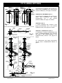
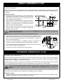
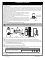
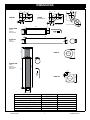
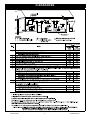
FF Flue
Installation
Manual
Rinnai FF coaxial flue system, suitable
for use with the following Rinnai internal
continous flow water heater models:
INFINITY 26i
HD 200i
UP
These components shall be installed in accordance with:
• Manufacturer’s Installation Instructions
• Current AS/NZS 3000, AS/NZS 3500 & AS 5601
• Local Regulations and Municipal Building Codes
These components must be installed, serviced and removed by an Authorised Person.
–
–
REU-VR2632FFUG
REU-VRM2632FFUC
INSTALLATION GENERAL
This flue must be installed by an authorised person. The Installation must conform to local
regulations.
Installation must comply with the instructions supplied by Rinnai.
Service and removal must be carried out by an authorised person.
TABLE OF CONTENTS
CERTIFICATION ....................................................................................... 1
GENERAL .................................................................................................. 1
FF FLUEING OPTIONS ............................................................................. 2
GENERAL INSTALLATION METHODS ................................................... 3
DIRECT HORIZONTAL FLUE ................................................................... 4
EXTENDED HORIZONTAL FLUE ............................................................. 4
VERTICAL FLUE ....................................................................................... 5
COMBINED VERTICAL & HORIZONTAL FLUE ...................................... 5
CONDENSATE DRAIN .............................................................................. 6
DIMENSIONS ............................................................................................ 8
CLEARANCES .......................................................................................... 9
CONTACT INFORMATION ..................................................................... 10
CERTIFICATION
Certified by the Australian Gas Association (AGA) For use only with Rinnai internal continuous flow water heaters.
GENERAL
1. These instructions only apply to the Rinnai FF water heater coaxial flueing system. This flue system utilises pipe
components with an aluminium inner pipe and a white plastic outer pipe.
These instructions DO NOT apply to older Rinnai water heater flueing that has either a stainless steel single skin
or stainless steel coaxial construction. If in doubt contact Rinnai.
2. Before commencing installation, please read the 'Installation Instructions - General', located inside a pouch
behind the front cover of all Rinnai water heater models. The Rinnai internal water heater range must only be
installed with Rinnai water heater flueing as referred to in these instructions.
3. The requirements of the current AS5601/AG601 and local authorities must be met, which is the installers
responsibility.
4. The required clearances of Rinnai internal continuous flow water heater when installed as a single unit are shown
in Fig.1A. The appliances are certified to be installed side by side as shown on page 7, allowing a minimum
distance between flues as follows:
• 270mm between horizontal terminals.
• 160mm between vertical cowls.
5. Rinnai internal continuous flow water heaters fitted with FF flue systems are room sealed as defined in AS5601.
No ventilation in the space where the water heater is installed is required.
6. The outer plastic section of the coaxial flue complies with temperature hazard requirements and can be installed
with zero clearance to combustible material.
Rinnai Australia
1
Installation Manual
FF FLUEING OPTIONS
FFSBEND
FFWPLATE or
FFWSEAL (Optional)
FFWPLATE or
FFWSEAL (Optional)
FFSBEND
127mm Hole
DIRECT HORIZONTAL (FIG. 1)
127mm Hole
2° fall to
terminal
2° fall to
terminal
FFWPLATE
FFWPLATE
FFWALLTERM
Drain Tube Cap
FFWALLTERM
Drain Tube Cap
45 minimum
FFPIPE1000
VERTICAL (FIG. 3)
A vertical installation that consists of flue
pipe(s) (FFPIPE1000) and a roof terminal
(FFROOFCOWL). See page 5 for details.
FFWALLTERM
VERTICAL / HORIZONTAL (FIG. 4)
2° fall to
terminal
Fig. 2
Drain Tube Cap
Fig. 3
FFROOFCOWL
Minimum
Clearance
500 mm
FFROOFCOWL
A combination of pipe(s) (FFPIPE1000) and
bends (FFSBEND/FFBEND) that terminate
with either a wall (FFWALLTERM) or roof
(FFROOFCOWL) terminal. See page 5 for
details.
For condensation drain fitting requirements
see the section “CONDENSATE DRAIN” on
page 6.
Minimum
Clearance
500 mm
Decktite or lead
collar flushing
HORIZONTAL EXTENDED (FIG. 2)
A horizontal flue installation that consists of a
starter bend (FFSBEND), flue pipe(s)
(FFPIPE1000)
and
a
wall
terminal
(FFWALLTERM). See page 4 for details.
Fig. 1
FFSBEND
A horizontal flue installation that consists of a
starter bend (FFSBEND) and a wall terminal
(FFWALLTERM) only. See page 4 for details.
Decktite or lead
collar flushing
Flue pipe clip
supplied with
FFROOFCOWL
Flue pipe clip
supplied with
FFROOFCOWL
Flue pipe clip
supplied with
FFPIPE1000
Flue pipe clip
supplied with
FFPIPE1000
FFWSEAL
FFPIPE1000
FFPIPE1000
Flue pipe clip
supplied with
FFPIPE1000
FFWSEAL
FFBEND
UP
FFPIPE1000
FFPIPE1000
Drain Tube
(See Page 6)
FFPIPE1000
UP
FFWALLTERM
UP
FFPIPE1000
FFBEND
2° fall to
Termina
FFBEND
FFPIPE1000
FFSBEND
UP
2° fall
to trap
Drain Tube
(See Page 6)
Rinnai Australia
Fig. 4
Flue pipe clip supplied with FFPIPE1000
2
Installation Manual
GENERAL INSTALLATION METHODS
Lubricating Components
A container of "O ring" grease is provided with the flue terminal components (FFWALLTERM and FFROOFCOWL).
To ease assembly, lubricate the “O” ring on the inner pipes of each flue component prior to assembly.
Use only a silicone based "O" ring seal lubricant. DO NOT use petroleum based lubricants such
as petroleum jelly, as such products may cause deterioration.
Flue Length Dip switch Settings
Means of disconnection
The appliance connection shall include a means
of disconnection in accordance with AS5601.
OFFON
OFFON
SW1
SW1
This increases the combustion fan speed to
overcome the additional friction losses.
SW2
Fig. 6
Cutting The Flue Components
Using the dimensions shown on page 8, calculate the required number and type of
flue components that are needed to reach from the water heater and the flue
terminal.
OFFON
1 2 3 4 5 6
Dipswitches
SW2
OFFON
SW2
1 2 3 4 5 6
If flue length exceeds 1.5m, dipswitch 1 of SW1 is
to be switched to the 'OFF' position (Fig. 6).
1 2 3 4 5 6 7 8
Dipswitches
SW1
FFU (Internal) Models Only
Extended Flue: Total flue
length 1.5 metres or greater
1 2 3 4 5 6 7 8
Setting Flue Length Dipswitch
Installations can consist of both horizontal and
vertical runs to a maximum length of 9 metres and
with a maximum of three 90° bends.
FFU (Internal) Models Only
Short Flue: Total flue
lentgh less than 1.5 metres
50
35
15
When cutting components the outer flue pipe should be cut to the required length
plus 35 mm and the inner flue pipe should be cut to the required length plus 50 mm,
this will ensure that the correct penetration is provided for joining of components.
When inner and outer pipes are re-assembled after cutting the inner pipe should
extend 15mm beyond the end outer pipe (Fig. 7).
Penetration
Required length
Fig. 7
The ONLY COMPONENTS that can be cut are as follows: FFPIPE1000, FFROOFCOWL and
FFWALLTERM.
Ensure all ends are cut square (the use of a mitre box will ensure a clean square cut).
Ensure all cut ends are free from debris and burrs.
Flue Terminals
The flue gases can reach temperatures up to 200°C. The flue terminal is to terminate in a location
not to cause a nuisance, in accordance with AS5601.
Multiple Terminal Installations
The terminal clearances in AS5601 do not apply
to the Rinnai internal continuous flow water
heaters when installed side by side (Fig. 8).
AGA certification allows for a horizontal
separation of 160 mm for roof terminals and 270
mm for wall terminals.
Each terminal is to be terminated at the same
vertical height.
Fig. 8
Rinnai Australia
3
Installation Manual
DIRECT HORIZONTAL FLUE
The Rinnai water heater 'direct' flueing components (FFSBEND, FFWALLTERM, FFWSEAL and FFWPLATE) must
be used for this purpose.
Mount the water heater in an appropriate location ensuring that there is enough space to install the flue assembly
and pipe work. Also ensure that positioning of the flue terminal complies with the requirements of AS5601 (Fig.5.3
on page 9).
Ø127 Wall penetration
FFSBEND
2. When installing the FFSBEND directly backwards from the
appliance it is necessary to extend the adjustable mounting
brackets of the water heater to a minimum of 45mm to
allow for the flue component radius.
160
Installation method
1. Using the dimensions provided in Fig. 9, mark a point along
the appliance centring that is 160mm from the top of the
water heater. This mark forms the centre point for the
127mm diameter wall penetration.
3. Make a 127mm wall penetration for the flue. Ensure that
the flue spigot is covered to avoid debris entering the
appliance flue connection.
Fig. 9
130
5
Min
45
If an accurate wall penetration is made then the FFSBEND will cover the hole and an internal wall
plate will not be necessary.
Ensure the drain tube cap remains fitted in place (Fig. 10).
1. Measure the required length for the horizontal terminal to penetrate the wall
and allow an extra 10mm protrusion from the wall outer surface as shown in
Fig. 10. See the section “Cutting The Flue Components” on page 3 for
correct cutting requirements.
2. Connect the FFWALLTERM to FFSBEND (ensuring components are
pushed 'fully home') and fit associated wall plates/seals as required.
3. To prevent rain water from entering the flue terminal ensure the required 2°
fall to outside is achieved (Fig.2 page 2).
10
Drain
Tube
Cap
Fig. 10
4. Seal the flue around the wall plate using silicon sealant.
EXTENDED HORIZONTAL FLUE
This option can be used when the water heater is mounted against an internal wall and flueing needs to extend
horizontally to exit an external wall.
As with the DIRECT HORIZONTAL FLUE option the Rinnai water heater 'direct' flueing components (FFSBEND,
FFWALLTERM, FFWSEAL and FFWPLATE) must be used for this purpose, together with extension pieces
(FFPIPE1000 and FFBEND) components as required.
Total flue length can be up to 9 metres long and a maximum of 3 bends can be used. Horizontal flue is to be installed
with a 2° fall towards the wall terminal to prevent condensation running back into the water heater.
If this can not be achieved and the length of the flue system exceeds 1.5 metres the condensate
drain pipe will require connection, refer to “CONNECTING CONDENSATE DRAIN” on page 6 for
details.
Ensure there is enough space to install the water heater, flue assembly and pipe work. Also ensure that positioning
of the flue terminal complies with the requirements of AS5601 (Fig.5.3 on page 9).
Installation method
1. Follow the installation method as described for the DIRECT HORIZONTAL FLUE option, using FFPIPE1000 and
FFBEND components to extend the installation as required.
Rinnai Australia
4
Installation Manual
VERTICAL FLUE
This option can be used when the water heater is to be flued vertically through the roof.
The Rinnai water heater 'Vertical Flueing Components' (FFROOFCOWL and FFPIPE1000) with extension pieces
(FFPIPE1000) and optional roof seal (FFSEAL) must be used for this purpose.
With vertical flue systems the condensate drain pipe will require connection if the total length of
the flue system exceeds 2 metres. Refer to the section “CONDENSATE DRAIN” on page 6 for
details. If the condensate drain tube is not required to be connected it is important to keep the
drain tube cap in place on the appliance flue spigot. It is only to be removed if the condensate drain
tube is connected. Appliances must not be operated with the drain tube cap removed and with no
condensate drain tube connected.
Total flue length can be up to 9 metres long and have a maximum of 3 bends.
Mount the water heater in an appropriate location ensuring that there is enough space to install the flue assembly
and pipe work. Also ensure that positioning of the flue terminal complies with the requirements of AS5601 (Fig.5.3
on page 9).
Installation method
1. Set plumb bob from the centre of the heater flue outlet to ceiling marking position. Cut 127mm hole in
plasterboard (or a suitable 'oval' for pitched roof applications). Repeat this step for underside of roofing.
2. Calculate the required number and combination of FFPIPE1000 lengths and cut to size as required, see the
section “Cutting The Flue Components” on page 3.
3. Install flue and terminal. Flue to terminate at least 500mm from the end of the flue to the nearest part of the roof,
in accordance with AS5601(Fig. 3 page 2). Seal the roof penetration with an approved flashing.
4. Install roof seal. (Not supplied, if required Rinnai Part No. FFWSEAL).
5. Ensure the flue is fully supported independently of the appliance, by the use of suitable clips or brackets, in
accordance with AS5601. Appropriate standoff brackets are supplied with each FFROOFCOWL and
FFPIPE1000 component.
6. Ensure that the appliance can be removed without causing movement or displacement of the flue, in accordance
with AS5601.
7. Fit the condensate drain tube if required (see “CONDENSATE DRAIN” on page 6).
8. All external joints of the PVC pipe must be glued with approved PVC cement to prevent water entering the flue.
COMBINED VERTICAL & HORIZONTAL FLUE
This option allows the water heater to be installed virtually anywhere using a wall (FFWALLTERM) or roof
(FFROOFCOWL) terminal. Extension pieces (FFPIPE1000 and FFBEND) can be mounted horizontally or vertically
as required.
With combined horizontal and vertical flue systems the condensate drain pipe will require
connection if the total length of the flue system exceeds 1.5 metres. Refer to the section refer to
“CONNECTING CONDENSATE DRAIN” on page 6 for details. If the condensate drain tube is not
required to be connected it is important to keep the drain tube cap in place on the appliance flue
spigot. It is only to be removed if the condensate drain tube is connected. Appliances must not be
operated with the drain tube cap removed and with no condensate drain tube connected.
Total flue length can be up to 9 metres long and have a maximum of 3 bends. Mount the water heater in an
appropriate location ensuring that there is enough space to install the flue assembly and pipe work. Also ensure that
positioning of the flue terminal complies with the requirements of AS5601 (Fig.5.3 on page 9).
Installation method
1. Using a combination of the installation procedures covered in the “EXTENDED HORIZONTAL FLUE” on page 4
and “VERTICAL FLUE” on page 5 determine and install the required components.
Rinnai Australia
5
Installation Manual
CONDENSATE DRAIN
The condensate trap and associated drain connection are integral with the appliance flue spigot. The condensate
trap collects any condensate from the flue system, thereby preventing condensate from entering the water heater
and causing damage.
A condensate drain tube kit is supplied with the terminals (FFWALLTERM and FFROOFCOWL) and will require
connection to the condensate drain connection in flue systems where the total length exceeds 1.5 metres AND
condensate cannot be drained via the flue terminal. Usually, the condensate drain tube requires connection in
‘vertical flue’ and ‘combined vertical & horizontal flue’ systems and does not require connection in ‘direct horizontal’
and ‘extended horizontal’ flue systems.
If the condensate drain tube is not required to be connected it is important to
keep the drain tube cap in place on the appliance flue spigot. It is only to be
removed if the condensate drain tube is connected (Fig. 11).
Appliances must not be operated with the drain tube cap removed and with no
condensate drain tube connected.
Drain Tube Cap
Because the condensate is a by-product of gas combustion it is mildly acidic.
For this reason copper tube and fittings MUST NOT be used as it will corrode.
Instead, Rinnai recommend plastic pipes and fittings such as Unplasticised
Polyvinyl Chloride (UPVC) or Polyethylene (PE) which is commonly used for
irrigation piping.
Fig. 11
Important Considerations For The Condensate Drain Tube
The content of AS3500.4:2003 Section 5.12 ‘Temperature / Pressure Relief and Expansion Control
Valve Drain Lines’ has been used as a guide in preparing these considerations.
C
D
A B C
D
B
2° fall
A
A B C
E
F
Fig. 12
G
A
Flue spigot with integral condensate trap. Water heater drain outlet connection is 16mm.
B
Aluminium condensate drain tube. (Supplied with flue terminals FFWALLTERM or FFROOFCOWL).
C
Silicone connection tube and retaining clips. (Supplied with flue terminals FFWALLTERM or FFROOFCOWL).
D
Continuous fall (of at least 2°) from water heater to discharge point. Lengths and bends in accordance with
‘length And Changes Of Direction’ table below.
E
16 mm UPVC conduit to terminate in accordance with
F
Drainage tube to be sealed to conduit with approved silicone.
G
Suitable points of discharge are deemed to be drains, sewers or pits. DO NOT discharge onto electrical
connections, earth stakes, copper pipes, concrete paths or into a pond.
G
.
Lengths and changes of direction
Max length (Metres)
Maximum length and changes of direction
greater than 45 ° should be as follows:
Max changes of direction >45°
9
8
7
6
3
4
5
6
Installation Method
(a) The drain line MUST NOT discharge onto electrical connections, earth stakes, copper pipes, concrete paths or
into a pond.
Rinnai Australia
6
Installation Manual
CONDENSATE DRAIN
(b) The point of discharge from each drain line shall be located so that the release of condensate does not cause a
nuisance, is readily discernible and incurs no risk of damage to the building.
In view of (a) and (b), suitable points of discharge are deemed to be drains, sewers or pits.
(c) There shall be no tap, valve or other restrictions in any line.
(d) Each line shall fall continuously from the valve to the approved point of discharge.
(e) Drain lines shall not discharge into a storage water heater safe tray.
(f) The end of the condensate drain line shall be:
(i) not lower than 200 mm or higher than 300 mm above an un-paved surface; or
(ii) not lower than 75 mm or higher than 300 mm above a gravel pit not less than 100 mm in diameter in a paved
surface.
(g) Where discharging over a tundish or gully trap, drain lines shall have an air gap of a size at least twice the
diameter of the drain line.
Interconnection Of Condensate Drain Lines
Condensate drain lines from multiple water heaters may be joined together provided they conform with the
‘INSTALLATION’ requirements on page 6.
Common Stack Discharge
Where individual water heaters are installed in a multistorey building, the condensate drain lines may discharge into
a common stack, subject to the following:
(a) The discharge from the common stack is to a tundish, having a discharge line, that is not less than the size of
the common stack, directly connected to a fixture trap, and installed in connection with any adjacent soil or waste
stack.
(b) The discharge point of the common stack is such that any discharge is readily visible and not cause any
nuisance.
(c) The common stack is vented by extending the pipe upwards, above the roof level.
Tundish Drain Lines
The drain line from any tundish shall be not less than DN 20 or less than one size larger than that of the largest drain
line discharging into the tundish. Tundish drain lines shall comply with the ‘INSTALLATION’ requirements on
page 6.
Areas Subject To Freezing
In areas where water pipes are prone to freezing, the drain pipe from any valve shall be insulated and not exceed
300 mm in length. It shall discharge into a tundish through an air gap of not less than 75 mm and not more than 150
mm measured from the outlet of the drain pipe to the rim of the tundish.
Rinnai Australia
7
Installation Manual
DIMENSIONS
64.5
165
85
5
176
66
80
85
FFBEND
(2x 45° Bends)
114
85
FFSBEND
15
80
15
15
92
5
5
166
130
66
64.5
490
15
80
(As a 45° OFFSET)
(As a 90° OFFSET)
75
125
Includes:
Drain tube
Silcone lubricant
80
FFWALLTERM
15
975
5
FFWSEAL
85
125
225
125
290
UP
Includes:
Wall bracket
80
FFPIPE1000
Thickness 1mm
FFROOFCOWL
765
1060
Includes:
Drain tube
Silcone lubricant
Wall bracket
20
127
200
FFWPLATE
20
Ø6 x 4
15
Thickness 1mm
80
125
DESCRIPTION
Starter Bend
Universal 45/90 Degree Bend
Horizontal Flue Terminal
Flue Pipe 1000mm length
Vertical Flue Terminal
Ceiling Ring
Wall Plate
Rinnai Australia
CODE NUMBER
FFSBEND
FFBEND
FFWALLTERM
FFPIPE1000
FFROOFCOWL
FFWSEAL
FFWPLATE
8
BAR CODE NUMBER
9314109158311
9314109143058
9314109107685
9314109107061
9314109107678
9314109107722
9314109107715
Installation Manual
CLEARANCES
Rinnai Australia
9
Installation Manual
CONTACT INFORMATION
Australia Pty. Ltd.
Internet: www.rinnai.com.au E-mail: [email protected]
ABN 74 005 138 769
Head Office
National Help Lines
10-11 Walker Street,
Braeside, Victoria 3195
P.O. Box 460
Tel: (03) 9271 6625
Fax: (03) 9271 6622
Sales & Service
Tel: 1300 555 545* Fax: 1300 555 655*
Spare Parts & Technical Info
Tel: 1300 366 388* Fax: 1300 300 141*
*Cost of a local call Higher from mobile or public phones.
Hot Water Service Line
Tel: 1800 000 340
Rinnai has a Service and Spare Parts network with personnel who are fully trained
and equipped to give the best service on your Rinnai appliance. If your appliance
requires service, please call our Hot Water Service Line. Rinnai recommends that
this appliance be serviced every 3 years.
10
RA TSD01-011 Issue 4.0 12/06/08