1
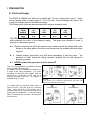
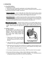
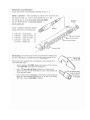
OWNERS MANUAL
TBA & TBA CORE DRILLS
TBA & TBA CORE DRILL STAND
FORM <<7202005
2
Important: Before placing equipment in operation, record the following
information.
MODEL:_________________ SERIAL NO.___________
PURCHASE FROM: _____________________________
ADDRESS: ____________________________________
CITY__________ STATE _________ ZIP ___________
TELEPHONE NO. _______________________________
Before using this equipment, make sure that person using it read and
understand the instructions in this owners manual.
TBA & TBA CORE DRILL
3
CONTENTS
GENERAL INFORMATION
Inside
Cover
Warranty Infromation
I.
Preparation
A. Safety Precautions
B. General Information
C. Bit Installation
D. Water Supply
E. Electrical Supply
II.
A.
B.
C.
D.
PAGE
4
5
5
5
6
Operation
Core Drill Positioning
Drilling Technique
Vacuum Hold Down Operation (Optional)
Water Collector Operation (Optional)
7
7
8
8
III. Maintenance and Component Description
9
10
11
11
11
12
12
12
13
A. Motor Specifications (Cardi)
B. Motor Specifications (Milwaukee)
C. Vacuum Pump
D. Leveling Screws
E. Carriage
F. Gibs
G. Motor Spindle
H. Vacuum Seal
I. Electrical Wiring Diagram
IV. Parts List Section
A. Ordering Information
B. Optional Accessories
C. Assembly Drawings
D. Service Parts List
E. Operating & Maintance Instructions Gast Vaccum Pump
F. Cardi Authorized Repair
G. Milwaukee Authorized Distributors
H. Gast Pump Authorized Distributors
I. Machine Service Log
4
14
14
16-19
16-19
20
23-26
27
28
I PREPARATION
A. Safety Precautions
IMPORTANT! THE FOLLOWING SAFETY PRECAUTIONS MUST BE OBSERVED.
1. Know your core drilling machine! Read the Operator’s manual carefully. Learn the operation,
application and limitations, as well as the specific potential hazards peculiar to this equipment.
2. Ground the machine! The core drill must be grounded while in use to protect the operator from
electric shock. The motor is equipped with a three prong grounding type plug to fit the proper type
receptacle. The green [or green & yellow] conductor in the cord is grounding wire.
3. NEVER connect the green [or green & yellow] wire to a live terminal.
4. Use only three-wire grounded extension cords suitable for use outdoors and of sufficient gage to
accommodate power requirements.
5. Replace frayed or damaged extension cords.
6. Keep the work area clean avoiding cluttered work areas.
7. Consider the work area environment!
¾ Do not expose power tools to rain.
¾ Wear rubber boots to further insulate yourself from the drill.
¾ Mop up all excessive water around the work area before and after drilling.
¾ Keep the work area well lit.
8. Use extreme caution when drilling through floors. Provide for protection of all personnel and material
below the area. Cores generally drop from the drill bit at the completion of the hole.
9. Keep visitors away. Do not let visitors contact tool or extension cord. All visitors should be kept at a
safe distance from the work area.
10. Do not force the bit into the drilling surface.
¾ Use an anchor bolt , ceiling jack or vacuum hold-down attachment when drilling vertically
(ÐÏ) into floors.
¾ Only use an anchor bolt or ceiling jack when drilling horizontally (ÕÖ) into a wall or any other
vertical surface.
11.
Dress properly for the work being performed.
¾ Do not wear loose clothing or jewelry which can get caught in moving or rotating parts.
¾ Rubber gloves and non-skid footwear is recommended when working outside.
¾ Wear protective covering to contain long hair.
12.
Don’t abuse the cord. Never carry the tool by the cord or yank the cord to disconnect the plug
from the receptacle.
13.
Secure the drill stand to the work surface.
Use an anchor bolt, ceiling jack or vacuum
attachment to secure the drill stand to the work surface.
14.
NEVER stand on the drill stand base as a method of securing the drill stand!
15.
Don’t overreach! Keep proper footing and balance at all times. The slippery surface created
during the drilling operation results in unstable footing.
16.
ALWAYS disconnect the power before servicing or changing accessories or bits.
17.
ALWAYS check, then make sure wrenches are removed from the motor spindle and bit adapter
before connecting power or starting the drill motor.
18.
ALWAYS make sure power switch is in “off” position before connecting drill to power.
Caution: It is very important that the drilling machine is properly secured to the work surface. Movement
during drilling will cause bit chatter against work surface, fracturing diamonds or binding bit in the hole.
I PREPARATION
B. General Information
The Dr520 & Dr620 core drills are available with different power units.
MANUFACTURER
MILWAUKEE
Cardi
MILWAUKEE
AMPS
15
20
20
VOLTS
115
115
115
PHASE
SINGLE
SINGLE
SINGLE
HERTZ
60
60
60
All motors are single phase with two-speed selector switches. The 115 volt motors will
operate within a power range of 110 to 120 volts.
C. Bit Installation
The threads on the output spindle of the core drill motors have dimensions of 1-1/4"-7.
Core bits are available in a variety of diameters. The spindle thread on the adapter nut of
the core bit is 5/8-11 on smaller diameter bits. The use of an adapter coupling part
number 400148 is required in order to run smaller diameter bits. The adapter provides a
coupling which has a female 1-1/4"-7 thread on one side and a 5/8"-11 spindle on the
other end.
Core Bit Adapter
Part Number 400148
1. Using a wrench to firmly hold the output shaft , screw the core bit onto the spindle until
snug.
2. Placing one wrench on the machined flats of the output shaft and one wrench on the
end adapter of the core bit tighten the bit on the spindle. Note: Attempting to turn the
bit by the barrel rather than by the adapter nut may break the weld between the
adapter nut plate and the barrel.
D. Water Supply
It is important when wet cutting to maintain an
adequate supply of clean water to the diamond
drill bits. The hose input adapter on the water
swivel at the base of the core drill motor is used
to connect the water supply hose to the core
drilling unit. Special precautions should be
taken to insure that the water supply will not be
interrupted during the drilling operation.
Hose Input Adaptor
6
I PREPARATION
E. Electrical Supply
The DR520 & DM620 core drills are furnished with 115 volt, single phase motors. These
motors operate within a power range of 110 to 120 volts. Serious damage can result if the
supply line voltage does not fall within this range.
The following wire sizes are recommended when using an extension cord:
DISTANCE
FROM
SOURCE
Wire
Gauge
115 volt
25
FEET
115 volt
50
FEET
115 volt
75
FEET
115 volt
100
FEET
# 14
# 12
# 10
# 08
The DR520 & DR620 core drills are manufactured with a three conductor connector cord
which attaches the motor to the electrical supply. The green wire provided is used to
connect to a permanent ground.
z a. Before connecting the drill to the power source, make sure that the voltage and cycles
shown on the name plate of the motor are the same as the available electrical power
supplied.
z
b.
Always properly ground the core drill before attempting to start the motor. The
presence of water during the drilling operation requires that the drill always be
properly grounded.
z c. NEVER connect the green wire to a live terminal !
The use of 3-prong adapter is prohibited in Canada
by the Canadian Electrical Code.
An adapter, Fig. "B" is available for connecting Fig.
A plugs to two prong receptacles. The green
grounding ear extending from adapter must be
connected to a permanent ground such as to
properly grounded outlet box. No adapter is
available for fig "C" plugs.
NOTE: RECEPTACLE MUST BE GROUNDED FOR SAFE USE OF
ADAPTER:
IF IN DOUBT CALL A QUALIFIED ELECTRICIAN AND HAVE THE
RECEPTACLE CHECKED FOR GROUND
To connect twist lock plugs like those shown in
figures D and E, insert the plug into a matching
outlet. When the plug is fully inserted, turn it
clockwise until it locks. This prevents the plug from
being pulled out accidentally. To remove the plug,
twist it counterclockwise to unlock it and remove it
from the outlet.
7
II OPERATION
A. Core Drill Positions
To position the core drill:
1. Roll the drill so that the spindle is positioned over the desired drilling location.
2. Using the leveling screws located on the four corners of the base, level the core drill to
insure that the bit will drill a straight, vertical hole.
ÖCEILING BRACING - can be used when the ceiling above the work area is strong
enough to provide solid bracing. A length of pipe may be used with the adjustable brace
on the top of the drill column to firmly secure the drill against the work piece.
ÖANCHOR BOLTING - is a method used quite often in both horizontal and vertical drilling.
The anchor is secured in the work surface and the core drill is placed over the anchor bolt
so that the bolt goes through the hole in the center of the drill base. A nut and washer is
the used to pull the base down as the nut is screwed onto the anchor bolt.
ÖVACUUM HOLD DOWN - requires that the surface of the intended drilling area be
smooth or of an even texture in order to achieve an effective bond to the drilling surface.
A large hold down base and vacuum pump are used to fasten the drill to the work
surface. Both the pump and large base are available as optional accessories for the
drills.
B. Drilling Technique
The performance of any diamond core bit
depends heavily on the use of proper drilling
technique. Although drilling conditions and
materials may vary, following specific guide
lines insures faster drilling speeds and
longer bit life.
1. Secure the core drill to the work surface
so that there is no movement in the drill
that would cause the core bit to bind in
the hole.
Vacuum Pump Attachment
PART NUMBER: 407000
2. Insure that the hole is constantly flushed
of abrasive fines by supplying a sufficient flow of water.
3. Slowly lower the bit into the hole so that there is no skidding or lateral movement of the
drill. The entire circumference of the core bit should penetrate the drilling surface
before additional pressure is applied to the handle.
4. Exert steady downward pressure while drilling. NEVER force the bit into the material!
5. Do not stop the flow of water or rotation of the bit while the core bit is drilling.
6. Check the core bit if the drilling rate decreases noticeably. The slowing penetration
rate generally indicates that the bit is in need of reconditioning.
8
II OPERATION
C. Vacuum Hold Down Operation
The vacuum hold down base and pump work together to seal the drill to the work surface.
The vacuum pump requires 115 volt electrical supply. A 115 volt accessory outlet located
on the switch box is used to supply power to the vacuum pump. One outlet is consistently
supplied with power so that turning the motor off does not turn off the vacuum pump and
release the drill from the work surface.
1. Mount the column and carriage in the large vacuum hold down base.
2. Connect the vacuum pump to the vacuum base.
3. Wet the work area in order to achieve an effective seal.
4. Connect the vacuum pump cord into the top outlet of the receptacle in the switch box
above the motor. This will start the pump and create a seal between the base and the
work surface.
5. Adjust the leveling screws so that the core drill is level and resting lightly on the
vacuum seal.
6. Plug the vacuum pump cord into the live outlet of the receptacle in the switch box. This
will start the pump and create a seal between the base and the work surface.
7. Adjust the leveling screws so that the base is snug against the work surface. NOTE:
(Excessive tightening of the leveling screws will break the seal between the base and
the work surface).
8. To turn the vacuum pump off, unplug the power cord.
D. Water Collector Operation
The water collector unit (Part Number 402034) is designed to work with any core drill. It
can be used with any diameter core bit up to and including ten inch. The unit consists of a
tear dropped shaped ring with a rubber seal, a 115 volt electric water pump and a
drainage hose.
1. Place the pump in the small end of the tear-drop ring. Center the large area of the ring
over the area to be drilled.
2. Run the drainage hose from the pump to a drainage barrel and secure the hose to the
barrel with the hose hook.
3. PROPERLY GROUND THE PUMP, then plug it into the top outlet of the core drill
switch box.
4. Turn the pump off by unplugging the pump power cord at the cord drill switch box.
9
III. MAINTENANCE AND COMPONENT DESCRIPTION
A. Motor Specifications Cardi
Specifications
MFR
MODEL
VOLT
AMP
Cardi
D3-250
120
20
MOTOR RPM
LOW
HIGH
GEAR
GEAR
420
860
BIT CAPACITY IN
LOW
HIGH
GEAR
GEAR
8"-10"
4"-7"
*Refer to motor owners manual supplied with drill for required motor maintenance.
The Cardi motor is designed to operate at two
speeds. Changing speeds is accomplished by
using the speed shift knob built into the gear
case of the unit.
Changing the rpm of
accomplished as follows:
the
motor
is
1. Turn off switch, wait for spindle to stop then
rotate the shift knob to go from the
HIGH(••) to LOW(•) speed.
2. Move the shift knob until the clutch teeth
are fully engaged. Moving the knob toward
the single dot engages the LOW rpm while
moving the knob toward the two dots
engages the HIGH rpm.
3. Attempting to shift with the motor off may
require turning the spindle by hand to
engage the clutch.
Changing the rpm while the motor is running
will damge gears and void warranty.
10
III. MAINTENANCE AND COMPONENT DESCRIPTION
The vacuum pump is used with the large vacuum hold down
base to secure the core drill on smooth evenly textured
surfaces.
The
pump is powered
by a 115 volt, 4.2
amp,
60
hertz
electric motor. The
COMBINATION BASE
power cord of the
pump is plugged
into the live outlet
of the receptacle in
the switch box of
the core drill. The
switch box on the
drill allows the motor on the drilling unit to be turned
on and off without shutting down the vacuum pump
OPTIONAL
and breaking the seal between the drill base and the
work surface.
GAST VACUUM PUMP
The required maintenance procedure for the vacuum pump is listed in the "Parts List and
Operating and Maintenance Instructions" pamphlet. Parts for the vacuum pump are
available from local distributors of Gast products. A listing of Gast distributors is available in
this drill manual and in the vacuum pump pamphlet.
B. Leveling Screws
The four leveling screws on the base should cleaned with a mild solvent
and lubricated with a lightweight machine oil each time the machine is
used. Allowing the slurry to accumulate on the threads may cause damage
to the threads in the base.
C. Carriage
The carriage or head assembly should be cleaned and lubed with a
lightweight machine oil each time the machine is put away. Allowing slurry
to build on the column and inside the carriage will prematurely wear the
pinion gear and gibs.
11
III. MAINTENANCE AND COMPONENT DESCRIPTION
D. Gibs
The gibs are brass wear shims used on the inside of the carriage which
allow the carriage to slide freely and rigidly on the column. The gibs require
periodic replacement. Replacing the gibs is necessary when the carriage is
no longer rigid on the column. Keeping the column free of excess debris
and burrs will maximize the service life of the gibs.
E. Motor Spindle
The motor spindle on all core drill motors is equipped with 1-1/4"-7 thread
dimensions. The end adapter of the core bit is also threaded 1-1/4"-7 on
core bits of 2 inches and larger diameter. Core bits with a diameter less
than 1-5/8 inches have 5/8”-11 threads and require the use of an adapter.
The motor spindle maintenance should be performed each time the
machine is stored for the day. Leaving the core bit on the motor spindle
may cause the threads on the spindle to rust making removal of the core bit
very difficult. After removing the core bit check the threads for any nicks or
burrs. The spindle should then be cleaned with a mild solvent and
lubricated with a lightweight machine oil.
Removing the core bit from the motor spindle by turning the core bit barrel
is not recommended. The core bit barrel may break the weld between the
adapter plate and barrel if excessive side pressure is applied. The best
results are achieved using two wrenches. One of the wrenches placed on
the machined flats on the motor spindle and the other wrench on the core
bit end adapter.
F. Vacuum Seal
The vacuum seal is the sponge rubber gasket which lines the bottom of the
large vacuum base. The material prevents air from entering the area under
the base. Thus allowing the vacuum to pull against the work surface. In
order for the seal to work properly the seal material must remain pliable and
in one piece with no gaps or inconsistencies on the surface. The vacuum
seal should be rinsed at the completion of each operation. Allowing the
slurry to accumulate on the gasket will cause the material to deteriorate
prematurely. The vacuum seal should be checked on a regular basis and
replaced if it has been damaged or started to deteriorate.
12
III. MAINTENANCE AND COMPONENT DESCRIPTION
G Electrical Wiring Diagram
BEFORE CONNECTING DRILL TO THE POWER SOURCE, MAKE SURE THE
VOLTAGE AND CYCLES SHOWN ON THE NAME PLATE AGREE WITH THE
AVAILABLE ELECTRICAL SUPPLY!
ALWAYS PROPERLY GROUND THE CORE DRILL!
NEVER CONNECT THE GREEN WIRE TO A LIVE TERMINAL!
INTERNAL WIRING DIAGRAM
See Page 19 For Switch Box Parts Breakdown
13
IV. PARTS LIST SECTION
A. Ordering Information
1. List model number of machine.
2. List part number and description of part (not item number).
3. Wherever alternate parts are shown due to product improvement, inspect the part
you have and provide additional description as necessary.
4. Specify mode of shipping desired, such as, parcel post, truck, air freight, U.P.S.,
best way, etc.
B. Optional Accessories
1. Vacuum Hold Down: Part Number 407000 Provides a means of securing the core
drill on smooth evenly textured surfaces without using anchors.
2. Water Collector Kit: Part Number 402034 recovers the excess water used during
the drilling operation and pumps it into a drum. The ring is used to limit the amount
of area that is exposed to water. The ring is best used in areas where the surface
texture is smooth and even.
3. Shaft Couplings: The couplings are used as adapters which decrease or increase
the spindle diameter and thread dimension.
Part Number
400145
400146
400147
400148
Spindle Thread
1/2"--20
5/8"--11
5/8"--11
1-1/4"--7
Adapter Thread
5/8"--11
1/2"--20
1-1/4"--7
5/8"--11
4. Shaft Extensions: Extend the depth to which a core bit will drill when the carriage
has reached the maximum travel distance of the column.
Part Number
402754
402755
402756
402757
402758
402759
Spindle Thread
1-1/4"--7
1-1/4"--7
1-1/4"--7
5/8"--11
5/8"--11
5/8"--11
Length
9"
3.5"
12"
12"
6"
3"
5. Motor Spacer Plate Kit: Part Number: 408002 Moves the motor away from the
column so that the drill will accept up to a fourteen inch bit.
14
B. Optional Accessories
UPC: 70184600938
Part
Number
408003
The Bit Slider
Helps prevent the core bit from
“sticking” on threads of spindle.
No more need for wrench and
hammer to remove core bits.
UPC: 70184675539
Part
Number
403126
15
Water Pressure Tank
4 Gallon capacity
Metal Construction
Fittings included
ASSEMBLY DRAWINGS
TBA & TBA
CORE DRILLS
16
IV. PARTS LIST SECTION
Product Breakdown:
Model
UPC
Description
DS5
70184600922
Rental Drill Stand Only
DR520
70184600924
DS5, Milwaukee 20A Drill Motor,
Vacuum Pump
DS6
70184600923
Professional Drill Stand Only
DR620
70184600925
DS6, Milwaukee 20A Drill Motor,
Vacuum Pump
DR620C
70184600926
DS6, Cardi 20A Drill Motor,
Vacuum Pump
DS5 & DR520
DS5 & DR520
Item No.
-NA-NA-NA-NA-NA-
Part#
407000
403064
403061
408001
408002
UPC#
70184679912
70184657985
70184657976
70184600916
70184600927
-NA1
2
3
4
5
6
7
8
9
408003
408004
408005
408006
407062
27006
408007
8177012
9048126
408008
70184600938
70184600985
70184600986
70184600987
70184679998
70184681615
70184600988
70184650149
70184600989
70184600990
10
11
12
13
14
15
16
17
408009
8041048
8041146
227146
27505
408010
408011
8042136
8177016
8172013
70184600991
70184649898
70184649936
70184674553
70184681623
70184600992
70184600993
70184600994
70184650156
70184650127
18
19
20
21
22
23
24
408012
408013
8041008
408014
9048092
9048090
408015
70184600983
70184600995
70184649881
70184600996
70184650195
70184600997
70184600998
25
26
27
28
29
30
408016
P110294
408017
408018
408019
8041002
70184600999
70184680687
70184601000
70184601001
70184601002
70184649875
31
408020
70184601003
Description
PUMP VAC ASSY W/FITTINGS
MOT 20A 115V MILW ASSY
MOT 15A 115V MILW ASSY
MOT 20A 115V CARDI D3-250
SPACER BLOCK DS5-DS6
QUICK DISCONNECT BIT
SLIDER
GIBB BRASS 3X16X215MM
GIBB BRASS 3X38X215MM LS
GIBB BRASS 3X38X215MM
SWITCH BOX
NUT M10 1.5 DIN934
BUSHING THREADED 3/8X5/8
WASHER 3/8 SPRING LOCK ZN
SCR 3/8-16 X 1 SOC HD CP
TUBE 3/8ID X 1/2OD X 1L
WRENCH ALLEN 8MM T
HANDLE
SCR 3/8-16 X 3/4 HEXHDCAP
SCR 5/8-11 X 3 HEXHDCAP
PIN COTTER 1/8 X 1-1/2
WASHER M20 DIN125
WHEEL 6 X 1-3/8 X 3/4 (2)
WHEEL DOLLY BRACKET DS5
SCR 5/8-11 X 1 HEXHDCAP
WASHER 5/8 SPRING LOCK
WASHER 5/8 SAE
GASKET VACUUM BASE DS5DS6
SCR 1/4-20 X 1/2 FHCP BRASS
SCR 1/4-20X1 1/2 HEXHDC
BUBBLE LEVELING
SCR 1/4-20X1 SOC HD CAP
SCR 1/4-20X3/4 SOC HD CAP
DOVETAIL MOUNT 30 X 125MM
MOTOR MOUNT PLATE DS5DS6
KEY 3/8 X 3/8 X 2
KNOB HANDLE DS5-DS6
HANDLE BAR DS5-DS6
HANDLE CARRYING DS5-DS6
SCR 1/4-20X1/2 HEXHDCAP
CARRIAGE LOCK 7/16-14 DS5DS6
Qty
Opt
Opt
Opt
Opt
Opt
Opt
2
1
2
1
2
1
1
1
1
1
3
4
4
4
2
1
2
2
2
1
9
1
1
6
4
1
1
1
2
1
1
2
1
DS5 & DR520
Item No.
32
33
34
35
36
Part#
408021
9083143
408022
8041095
8172011
UPC#
70184601004
70184601005
70184601006
70184649919
70184650124
37
38
39
40
41
42
43
44
408023
408024
408025
408026
408027
408028
408029
8041107
8172011
8177014
8143005
70184601007
70184601008
70184601009
70184601010
70184600984
70184601011
70184601012
70184649929
70184650124
70184650154
70184650358
Description
CARRIAGE DS5-DS6
SCR 7/16-14 X 1/2 SOC SET SCR
PINION GEAR DS5-DS6
SCR 1/2-13 X4 1/2 FULL TH
WASHER 1/2 SAE
COLUMN SUPPORT BRACKET
DS5-DS6
SLOT PLUG ONLY DS5-DS6
CEILING JACK DS5-DS6
COLUMN DS5-DS6
GASKET SLOT PLUG DS5-DS6
VACUUM MOUNT DS5-DS6
BASE DR5-DR6
SCR 1/2-13X4 1/2 HEXHDCAP
WASHER 1/2 SAE
WASHER 1/2 SPRING LOCK
NUT 1/2-13 HEX JAM
Qty
1
3
1
2
4
2
1
1
1
1
1
1
2
4
2
2
DS6, DR620, DR620C
DS6, DR620, DR620C
Item No.
-NA-NA-NA-NA-NA-
Part#
407000
403064
403061
408001
408002
UPC#
70184679912
70184657985
70184657976
70184600916
70184600927
-NA1
2
3
4
5
6
7
8
9
10
11
12
13
14
15
408003
408025
408030
27539
27003
408031
408032
8041095
408033
408034
408035
8041146
408024
408027
408036
408037
408029
408028
70184600938
70184601009
70184601013
70184600585
70184600850
70184601014
70184601015
70184649919
70184601016
70184601017
70184601018
70184649936
70184601008
70184600984
70184601019
70184601020
70184601012
70184601011
16
17
408012
408038
70184600983
70184601021
18
19
20
408039
9042088
P110294
70184601022
70184601023
70184680687
21
22
408016
9048092
70184600999
70184650195
23
24
408040
27006
70184601024
70184681615
25
26
27
28
29
408015
408007
9048090
408021
408013
70184600998
70184600988
70184600997
70184601004
70184600995
Description
PUMP VAC ASSY W/FITTINGS
MOT 20A 115V MILW ASSY
MOT 15A 115V MILW ASSY
MOT 20A 115V CARDI D3-250
SPACER BLOCK DS5-DS6
QUICK DISCONNECT BIT
SLIDER
CEILING JACK DS5-DS6
SCR M6 X 45 1.0 DIN933
WASHER M6 DIN125
NUT M6 DIN985 LOCK
SCR M6 X 12 1.0 DIN965 FHP
GEAR RACK DS6
SCR 1/2-13 X4 1/2 FULL TH
COLUMN DS6 W/TOP PLATE
SCR M4 X 6 0.7 DIN965 FHP
PLATE REINFORCEMENT DS6
SCR 5/8-11 X 3 HEXHDCAP
SLOT PLUG ONLY DS5-DS6
GASKET SLOT PLUG DS5-DS6
PLATE ANGLE GUIDE DS6
PLATE ANGLE ADJUST DS6
BASE DR5-DR6
VACUUM MOUNT DS5-DS6
GASKET VACUUM BASE DS5DS6
PLATE ANGLE ADJ BAR DS6
BRACKET ANGLE
ADJUSTMENT DS6
SCR 1/4-20 X 1/2 SHCP
KEY 3/8 X 3/8 X 2
MOTOR MOUNT PLATE DS5DS6
SCR 1/4-20X1 SOC HD CAP
GIBB TEFLON 5X38X215MM
3HOLE
NUT M10 1.5 DIN934
DOVETAIL MOUNT 30 X
125MM
BUSHING THREADED 3/8X5/8
SCR 1/4-20X3/4 SOC HD CAP
CARRIAGE DS5-DS6
SCR 1/4-20 X 1/2 FHCP BRASS
DS6, DR620, DR620C
Qty
Opt
Opt
Opt
Opt
Opt
Opt
1
1
2
1
6
1
2
1
4
2
4
1
1
2
1
1
1
1
1
1
2
1
1
4
1
1
1
1
6
1
6
DS6, DR620, DR620C
Item No.
Part#
UPC#
30
408041
70184601025
31
32
33
34
35
37
38
39
40
41
408042
408018
408022
408014
408017
408019
8041002
408020
9048126
408008
70184601026
70184601001
70184601006
70184600996
70184601000
70184601002
70184649875
70184601003
70184600989
70184600990
42
408009
70184600991
43
408043
70184601027
44
408044
70184601028
45
46
408045
8041107
8177014
8172011
8041056
8172009
8177012
8142003
8041048
27505
408010
227146
408046
8042136
70184601029
70184649929
70184650154
70184650124
70184649906
70184650123
70184650149
70184650349
70184649898
70184681623
70184600992
70184674553
70184601030
70184600994
47
48
49
50
51
52
53
Description
GIBB TEFLON 5X16X215MM
FRONT
GIBB TEFLON 5X38X215MM
2HOLE
HANDLE CARRYING DS5-DS6
PINION GEAR DS5-DS6
BUBBLE LEVELING
KNOB HANDLE DS5-DS6
HANDLE CARRYING DS5-DS6
SCR 1/4-20X1/2 HEXHDCAP
CARRIAGE LOCK DS5-DS6
SCR 3/8-16 X 1 SOC HD CP
TUBE 3/8ID X 1/2OD X 1L
WRENCH ALLEN 8MM T
HANDLE
BAR ANGLE ADJUSTMENT
DS6
KNOB ANGLE ADJUSTMENT
DS6
TUBE ANGLE ADJUSTMENT
DS6
SCR 1/2-13X4 1/2 HEXHDCAP
WASHER 1/2 SPRING LOCK
WASHER 1/2 SAE
SCR 3/8-16 X 2-1/2 HEXHDCAP
WASHER 3/8 SAE
WASHER 3/8 SPRING LOCK
NUT 3/8-16 HEX
SCR 3/8-16 X 3/4 HEXHDCAP
WASHER M20 DIN125
WHEEL 6 X 1-3/8 X 3/4 (2)
PIN COTTER 1/8 X 1-1/2
WHEEL DOLLY BRACKET DS6
SCR 5/8-11 X 1 HEXHDCAP
Qty
2
2
1
1
1
2
1
1
1
1
1
1
1
1
1
2
1
3
4
2
4
1
2
Vacuum Base Assembly: DR520, DR620, and DR620C
Item
-NA-
Part #
407000
70184679912
1
2
3
-NA407045
-NA-
-NA70184680257
-NA-
4
5
6
7
8
9
10
407047
407048
YD2700014
YD2700017
407051
407052
407053
70184680099
70184680184
70184670831
70184669874
70184681740
70184681741
70184681142
11
12
13
14
407054
407055
407056
9600004
70184680456
70184681205
70184681739
70184650460
15
16
17
18
8428001
407059
8404001
407061
70184650412
70184680050
70184650676
70184681100
Description
VACUUM PUMP ASSY 110-VOLT
(INCLUDES 1-18)
USE 407000
MUFFLER
USE YD2700014, YD2700017,407051,
407052, 407047, AND 407048
WATER TRAP JAR
FLOAT BALL
WATER TRAP TOP
WATER JAR GASKET
BRASS FUNNEL FITTING
O-RING
HOSE ASSY 9-1/4” LONG (INCLUDES
11-14)
¼” HOSE BARB TO ¼” MALE PIPE
HOSE CLAMP ½” PINCH ON
HOSE ¼” ID X 9-1/4” LONG
FITTING ¼” HOSE BARB TO 1/8”
MALE PIPE
PIPE TEE ¼” NPT
VACUUM GAUGE
CLOSE NIPPLE ¼” NPT
AIR PETCOCK
Qty
1
1
1
1
1
1
1
1
1
1
1
1
2
1
1
2
1
3
1
Electrical Box Assembly: DS5, DS6, DR520, DR620,
and DR620
Item
-NA-
Part #
407062
UPC#
70184679998
1
2
3
4
5
6
7
8
9
10
11
407063
407064
407065
8143005
407067
407068
407069
407070
407071
407072
407073
70184680763
70184681204
70184681768
70184650358
70184680712
70184683549
70184680070
70184680327
-NA70184683337
70184683434
Description
ELECTRICAL BOX ASSEMBLY 110-VOLT
(INCLUDES 1-19)
SWITCH BOX
SWITCH BASE
STUD ½”-13 X 2”
NUT 1/2-13 HEX JAM
RECEPTACLE 110-VOLT
SPACER GASKET
AMP METER 110-VOLT
TOGGLE SWITCH 20-AMP
ON-OFF PLATE
SEALING LOCK NUT ¾”
CORD CONNECTOR ¾”
Electrical Box Assembly: DS5, DS6, DR520, DR620,
and DR620
Qty
1
1
1
1
1
1
1
1
1
1
1
1
12
13
14
15
16
17
18
19
407074
407075
407076
407077
407078
407079
407080
407081
70184683550
-NA70184683550
70184683551
-NA-NA-NA70184682234
LINE CORD 110-VOLT
SCR #10-24 X 7/8” MACHINE ROUND HEAD
PLUG 30 AMP
MOUNT PLATE
SCR #6-32 X ½” MACHINE ROUND HEAD
WASHER #6 LOCK
NUT #6-32 HEX
TRANSFORMER 110-VOLT
1
4
1
1
2
2
2
1
I.
OPERATING AND MAINTENANCE INSTRUCTIONS
(GAST MODEL DOA-V185A-AA)
Do not at any time lubricate any of the parts with oil, grease, or petroleum products nor clean with acids, caustics or
chlorinated solvents. Be very careful to keep the diaphragm from contracting any petroleum product or hydro
carbons. It can affect the service life of the pump.
Danger: To prevent explosive hazard, Do NOT pump combustible liquids or vapors with these units.
Personal Injury and/or Property Damage would result.
To replace the diaphragm, remove the socket cap screws from the head of the pump. The diaphragm is held in
place by two Phillips head screws. Remove screws, retainer plate, and the diaphragm. The diaphragm will fit in any
position on the connecting rod. Replace the plate and the two Phillips head screws. Torque to 30 inch-pounds on
DOA and DAA. torque to 12 inch-pounds on MOA and MAA.
Caution: Do not raise any burrs or nicks on the heads of these screws. These burrs could cause damage to
the inlet valve.
For replacing the inlet and outlet valve, remove the slotted machine screw that holds each valve in place. The
stainless steel inlet and outlet valves are interchangeable.* Clean them with water. When replacing the outlet valve,
place the new valve in location and note there is a retaining bar near the machine screw hole. This retaining bar
holds the valve in position. When replacing the inlet valve, note that the valve holder is marked with an X in one
corner. This X should be in the lower right hand corner toward the inlet of the air chamber. Replace the head and
tighten the socket head screws to 90-100 inch-pounds of torque on DOA and DAA Torque to 30 Inch-pounds on
MOA and MAA. *DOA and DAA models only.
WARNING-The motor may be thermally protected and can automatically restart when the overload resets.
Always disconnect power source before servicing. Personal Injury and/or Property Damage could result.
Do not attempt to replace the connecting rod or motor bearings. If after cleaning the unit and/or installing a new
Service Kit, the unit still does not operate properly, contact your representative, the factory , or return the pump to
one of the GAST authorized Service Centers.
IF YOUR PUMP IS EQUIPPED WITH PLASTIC PLUGS IN THE EXHAUST AND/OR INTAKE PORTS, REMOVE
BEFORE STARTING UNIT.
WIRING INFORMATION
For any D.C. unit-red lead goes to positive side of power source.
For any permanent split capacitor motor which has four leads(4) leads is
as follows:
Brown leads to capacitor.
Black leads to Power Source.
For any permanent split capacitor for DOA & DAA motor which has (3)
leads is as follows: Figure 3
DO NOT ATTEMPT AT ANY TIME TO REMOVE THE CONNECTING ROD OR COMPLETELY
DISASSEMBLE THE PUMP. IF IT DOES NOT GIVE YOU THE PROPER SERVICE EVEN AFTER
INSTALLING A NEW SERVICE KIT, PLEASE RETURN IT TO ONE OF THE AUTHORIZED GAST
SERVICE CENTERS LISTED IN THE SERVICE CENTER PAGES.
OPTIONAL
VACUUM PUMP
GAST MODEL DOA-P101-AA
Parts available from local GAST distributors
GAST PUMP MODEL DOA-P101-AA
Parts for vacuum pump available through local GAST PUMP distributors
GAST
REF
NO.
1
2
3
4
5
6
7
8
9
10
11
12
12A
13
14
15
16
17
18
19
20
21
22
23
24
25
28
29
30
DESCRIPTION
COVER
HEAD GASKET
FILTER/MUFFLER ELEMENT
FILTER ELEMENT
HEAD
VALVE SCREW
VALVE RETAINER
LEAF VALVE
VALVE RETAINER
RETAINER PLATE
DIAPHRAGM
FELT SPACER
SPACER
FAN
GRILLE
RIVET
TANK
ADAPTOR PLATE
DRAIN VALVE
CHECK VALVE
PRESSURE GAUGE
GLOBE VALVE
PRESSURE SWITCH
PLASTIC TUBE
ELBOW
TEE
TUBE CONNECTORS
PLASTIC TUBE
ELBOW
SERVICE KIT
MUFFLER
PART
QTY.
1
2
2
1
1
2
1
2
1
1
1
3
1
1
1
4
1
2
1
1
1
1
1
1
1
1
1
1
1
1
1
PART
NO.
AF808
AF820
AG998A
AF857A
AF804
BB317
AF856
AF817
AF819A
AF809
AF818A
AA929
AG970
AF533
AF807
AE946
AC189
AF969
AE248
AE761A
AA806
AE251
AF564
AD159G
AE261B
BA418
AG247
AE814C
AE261A
K294A
AH190A
GAST PUMP SERVICE CENTERS
BRENNER-FIELD & ASSOCIATES
13824 Bentley Place
Cerritos, California 90701
[213] 404-2721
GAST MANUUFACTURING CORPORATION
2550 Meadowbrook Road
Benton Harbor, Michigan 49022
[616] 926-6171
GAST MANUUFACTURING CORPORATION
505 Washington Avenue
Carlstadt, NJ 07072
[201] 933-8484
WAINBEE, LIMITED
121 City View Drive
Rexdale, Ontario, Canada M9W 5A9
[416] 243-1900
WAINBEE LIMITED
215 Brunswick Boulevard
Pointe Claire, Montreal, Canada H9R 4R7
[514] 697-8810
GAST MANUFACTURING COMPANY., LTD
Halifax Road, Cressex Estate
High Wycombe, Bucks HP12 3SN
England
High Wycombe 23571
MILWAUKEE POWER TOOL SERVICE CENTERS
ANAHEIM
1130 North Magnolia Street
Anaheim, California 92801
Phone: 714 827-3970
213 624-7615
213 860-0349
ATLANTA
2381 John Glenn Drive
Suite 102
Chamblee, Georgia 30341
Phone: 404 455-7300
BOSTON
143 California Street
Newton, Massachusetts 02158
Phone: 617 244-4483
CHICAGO
7315 North Monticello Avenue
Skokie, Illinois 60076
Phone: 312 539-9173
CLEVLAND
7600 Wall Street
Cleveland, Ohio 44125
Phone: 216 524-8040
DALLAS
7205 Envoy Court
Dallas, Texas 75247
Phone: 214 637-4820
DENVER
2620 West 2nd Street
Denver, Colorado 80290
Phone: 303 922-1163
DETROIT
999 Troy Court
Troy, Michigan 48084
Phone: 313 585-8252
HOUSTON
4801 Katy Freeway
Houston, Texas 77007
Phone: 713 861-4671
KANSAS CITY
1506 Topping
Kansas City Missouri 64120
Phone: 816 241-7300
MIAMI
8101 North West 33rd Street
Miami, Florida 33122
Phone: 305 592-0442
MILWAUKEE
4057 North 128th Street
Brookfield, Wisconsin 53005
Phone: 414 781-0951
MINNEAPOLIS
2200 West 94th Street
Bloomington, Minnesota 55431
Phone 612 884-7258
NEW YORK
27-07 Brooklyn Queens Expressway W.
Woodside, New York 11377
Phone: NY 212 721-5151
NJ 201 622-7752
PHILADELPHIA
388 Reed Road
PO Box 224
Broomall, Pennsylvania 19008
Phone: 215 544-5544
Philadelphia: 215 528-6771
SAN FRANCISCO
329 Littlefield Avenue
South San Francisco, California 94080
Phone: 415 583-8484
San Francisco: 415 761-2851
SEATTLE
503 South Michigan Street
PO Box 80346
Seattle, Washington 98108
Phone: 206 762-8430
CARDI Core Drill Motor Model D3-250
CARDI Core Drill Motor Model D3-250
*Contact Factory for availability of parts.
I . Machine Service Log
Service Log
MODEL:________________________________Serial #:____________________________________
Date
Parts Serviced
Remarks
Saint-Gobain Abrasives, Inc.
Norton Construction Products
2770 West Washington Street
Stephenville, TX 76401
Phone: 800-554-8003
Fax: 800-443-1092