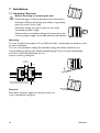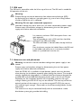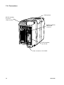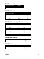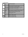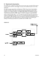
1
Users guide
6196-2230
Galvanic
Isolation
Transient
Protection
GSM
Modem
www.westermo.com
© Westermo Teleindustri AB • 2004 • REV.A
S
U
1
0
GD
Contents
1. Legal information
2. Description
3. Safety
...............................................................................................................................................
4
..................................................................................................................................................................
4
5–8
3.1 GSM specific ............................................................................................................................................................ 5
............................................................................................................................................................................
3.1.1 General ............................................................................................................................................................ 5
3.1.2 Hospital / Medical environment ................................................................................................... 6
3.1.3 Aircraft ............................................................................................................................................................. 6
3.1.4 Vehicle .............................................................................................................................................................. 6
3.1.5 For Vehicles equipped with an airbag ...................................................................................... 6
3.1.6 Blasting areas .............................................................................................................................................. 6
3.1.7 Explosive atmospheres ........................................................................................................................ 6
3.1.8 RF energy ....................................................................................................................................................... 7
3.1.9 Critical applications ............................................................................................................................... 7
3.1.10 Backup copies .......................................................................................................................................... 7
3.1.11 Antenna care ............................................................................................................................................ 7
3.2 Caution! ...................................................................................................................................................................... 7
3.3 FCC/Industry Canada Notice ................................................................................................................ 8
3.3.1 Statement according to FCC part 15.105 ........................................................................... 8
3.3.2 Statement according to FCC part 15.21 .............................................................................. 8
3.3.3. Statement according to FCC part 15.19 ............................................................................. 8
4. Approvals
.......................................................................................................................................................................
5. Specifications
2
..................................................................................................................................................
8
9–10
6696-2230
6. Care and Maintenance
7. Installation
..........................................................................................................................
11
12–16
7.1 Mounting / Removal ................................................................................................................................... 12
...................................................................................................................................................
7.2 SIM card ............................................................................................................................................................... 13
7.3 Antenna care and placement ............................................................................................................. 13
7.4 Connections ............................................................................................................................................ 14–17
7.4.1 Power interface .................................................................................................................................. 15
7.4.2 RS-232 interface, screw terminal ......................................................................................... 15
7.4.3 RS-232 interface, 9-pin D-sub .................................................................................................. 15
7.4.4 Antenna interface ............................................................................................................................. 15
7.4.5 SIM card interface ............................................................................................................................ 15
7.5 LED indicators ................................................................................................................................................ 16
7.6 Quick Start guide ......................................................................................................................................... 17
7.7 Configuration ................................................................................................................................................... 17
7.7.1 Service port .......................................................................................................................................... 17
8. Functional description
..........................................................................................................................
9. GSM network operators, subscriptions and services
10. Glossary
..................................
19
....................................................................................................................................................................
20
11. Related documents
6696-2230
18
...................................................................................................................................
21
3
1. Legal information
The content of this document are provided “as is”. Except as required by applicable law,
no warranties of any kind, either express or implied, including, but not limited to, the
implied warranties of merchantability and fitness for a particular purpose, are made in
relation to the accuracy and reliability or contents of this document.Westermo reserves
the right to revise this document or withdraw it at any time without prior notice
Under no circumstances shall Westermo be responsible for any loss of data or income
or any special, incidental, and consequental or indirect damages howsoever caused.
More information about Westermo can be found at the following internet address:
http://www.westermo.com
2. Description
The GD-01 US provide a reliable data communication link over GSM networks.
The unit has been designed for use in industrial data communication applications
and have several features that are not normally present on standard GSM modems.
The GD-01 US is a DIN-rail mounted modem with RS-232 interface in either a 9-pin
D-sub or in a 5-pin screw terminal.
Features:
…
…
…
…
…
…
…
…
…
Dual band GSM 850/1900 Mhz
GPRS
All configurations are done by industry standard AT-commands
Serial interface RS-232 D-sub or screw terminal
160 characters SMS
DTR-dialing
Isolated 12–36 VDC Power supply
Din-Rail mountable
LED indicators
The GD-01 US can be used in data communication applications together with other
GSM modems, traditional analogue PSTN modems (like the TD-33) or ISDN adapters
(such as ID-90). Packet switched data can be transferred via the GPRS service.
4
6696-2230
3. Safety
!
!
!
General:
Before using this unit, read this manual completely and gather all information
on the unit. Make sure that you understand it fully. Check that your application
does not exceed the safe operating specifications for this unit.
Before installation, maintenance or modification work:
Prevent damage to internal electronics from electrostatic discharges (ESD)
by discharging your body to a grounding point (e.g. use of wrist strap).
Hazardous voltage may occur within this unit when connected to power supply.
Prevent access to hazardous voltages by disconnecting the unit from power
supply and all other electrical connections.
Installation:
This unit should only be installed by qualified personnel.
This unit should be built-in to an apparatus cabinet, or similar, where access is
restricted to service personnel only.
The power supply wiring must be sufficiently fused, and if necessary it must be
possible to disconnect manually from the power supply. Ensure compliance to
national installation regulations.
This unit uses convection cooling. To avoid obstructing the air flow around the
unit, follow the spacing recommendations (see Installation section).
3.1 GSM specific
Important safety information / operating environment
Please read and follow the guidelines listed below.The precautions must be observed
during all phases of the operation. Breaking these rules may be dangerous, illegal or affect
performance of the unit and/or invalidate the units approval and/or warranty.
3.1.1 General
Remember to follow any special regulations and warnings in force in any area and never
use the unit whenever it’s forbidden to use it.
Do not use the unit when it may cause interference or danger. A wireless device
exposed to interference above specified limits could result in deteriorated performance.
6696-2230
5
3.1.2 Hospital / Medical environment
Do not use the unit in a medical environment such as health care facities. Follow any
regulations or rules that instruct you to not use the unit.
Medical equipment may be sensitive to RF energy.
If the unit is being used together with any medical devices (such as pacemakers, hearing
aids, etc.) consult the physician and/or the manufacturer of the device to determine if it
is adequately shielded from external RF energy.
3.1.3 Aircraft
Do not use the unit in an aircraft.The use of a wireless unit in an aircraft may be
dangerous to the operation of the aircraft, disrupt the wireless network, and may be
illegal.
Failure to observe these instructions may lead to suspension or denial of cellular services
to the offender, legal action, or both.
3.1.4 Vehicle
If the unit is incorrectly installed in a vehicular environment, the operation of the unit
could interfere with the vehicle electronics. Faulty installation and/or operation can
constitute a safety hazard.
3.1.5 For Vehicles equipped with an airbag
An air bag inflates with great force. DO NOT place objects, including either installed or
portable wireless equipment, in the area over the air bag or in the air bag deployment
area. If in-vehicle wireless equipment is improperly installed and the air bag inflates, serious injury could result.
3.1.6 Blasting areas
Do not use the unit where blasting is in progress or in “blasting areas”.
Observe restrictions and follow any regulation or rules.
3.1.7 Explosive atmospheres
Do not use the unit in any area with a potentially explosive atmosphere.
Potentially explosive areas are often, but not always, clearly marked.
They include fuelling areas such as petrol stations, below decks on boats, fuel or chemical
transfer or storage facilities, and areas where the air contains chemicals or particles, such
as grain, dust, or metal powder.
6
6696-2230
3.1.8 RF energy
The GD-01 US is a low power radio transmitter and receiver. When it is ON, it receives
and also sends out radio frequency (RF) signals.
Most modern electronic equipment is shielded from RF signals. However, certain electronic equipment may not be shielded against the RF signals from your wireless unit.
All radio transmitting devices send signals which may cause interference in different
electronic devices.To avoid interference, place the units antenna on a sufficiently long
distance from other electronics.
3.1.9 Critical applications
Cellular units operate using radio signals and cellular networks cannot be guaranteed to
connect in all conditions.Therefore you should never rely solely on a wireless device for
essential communications, for example medical emergencies.
3.1.10 Backup copies
Remember to make backup copies of all important data, for example PIN/PUK codes,
contents of SIM card etc.
3.1.11 Antenna care
Use only the supplied or an approved replacement antenna. Unauthorized antennas,
modifications, or attachments could damage the unit and may violate FCC regulations.
Do not touch the antenna unnecessarily when the unit is in use. Contact with the
antenna affects call quality and may cause the unit to operate at a higher power level
than otherwise needed.
The antenna connected to the unit is a magnetic mounted antenna with 0 dBd gain.
Using this antenna the total composite power in PCS mode is smaller than TBD watt ERP.
The antenna used for this mobile transmitter:
Part Number
3193-9047
Description
MiniMag Dual Band
Gain
0 dBd
Frequency range [MHz]
824–894, 1710–1880, 1850–2170
3.2 Caution!
In order to comply with FCC RF exposure requirements, install the GD-01 US and its
antenna so that a minimum distance of 20 cm (8 inches) can be maintained between the
antenna in use and all persons.The antenna used for this mobile transmitter must not be
co-located or operating in conjunction with any other antenna or transmitter.
6696-2230
7
3.3 FCC/Industry Canada Notice
3.3.1 Statement according to FCC part 15.105
NOTE:
This equipment has been tested and found to comply with the limits for a
Class B digital device, pursuant to Part 15 of the FCC Rules.These limits are
designed to provide reasonable protection against harmful interference in a
residential installation.This equipment generates, uses and can radiate radio
frequency energy and, if not installed and used in accordance with the instructions, may cause harmful interference to radio communications. However,
there is no guarantee that interference will not occur in a particular installation.
If this equipment does cause harmful interference to radio or television reception, which can be determined by turning the equipment off and on, the user is
encouraged to try to correct the interference by one or more of the following
measures:
• Reorient or relocate the receiving antenna.
• Increase the separation between the equipment and receiver.
• Connect the equipment into an outlet on a circuit different from
that to which the receiver is connected.
• Consult the dealer or an experienced radio/TV technician for help.
3.3.2 Statement according to FCC part 15.21
Modifications not expressly approved by Westermo could void the user's
authority to operate the equipment.
3.3.3. Statement according to FCC part 15.19
This device complies with Part 15 of the FCC Rules. Operation is subject to
the following two conditions:
(1) this device may not cause harmful interference, and
(2) this device must accept any interference received, including interference
that may cause undesired operation.
4. Approvals
EMC: FCC part 2, 15, 22 and 24
Network: PTCRB
Safety: UL 60950-1, CSA 22.2 No 60950-1-03 (first edition)
8
6696-2230
5. Specifications
GSM services
Circuit Switched Data
Fax
SMS
GPRS
Asynchronous transparent or non-transparent
up to 14.4 kbit/s
MNP2 error correction and V.42 bis data compression
Fax group 3 (Class 1 and Class 2)
160 characters text or PDU
Point to point (MT/MO)
Cell broadcast
GPRS Class 8, Class B
Coding scheme: CS1 to CS4
Power interface
GD-01 US
Rated voltage
Operating voltage
Rated current
online mode/
idle mode
Rated frequency
Connection
Connector size
12 – 36 VDC (reverse polarity protected)
10.8 – 39.6 VDC
350/40 mA @ 12 VDC
175/20 mA @ 24 VDC
117/17 mA @ 36 VDC
DC
Detachable screw terminal
0.2 – 2.5 mm2 (AWG 24-12)
Communication and service interface, RS-232
Electrical specification
RS-232
Data rate
300 bit/s – 115.2 kbit/s
Data format
7 or 8 databits, Odd, Even, None, Mark or Space parity
Connection
9-pin D-sub and 5-pin screw terminal
Circuit type
SELV, max 15 m length, shielding not required
Transmission range
15 m
Antenna interface
Frequency
Connection
GSM850: 824-849 and 869-894 MHz
GSM1900: 1.850 – 1.910 and 1.930 – 1.990 MHz
50 ohm impedance SMA female antenna connector
SIM interface
3 volts SIM cards supported
6696-2230
9
Mechanical
Dimension (WxHxD)
Weight
Mounting
Degree of protection
55 x 100 x 128 mm
0.3 kg
35 mm DIN-rail
IP 20 (IEC 529)
Isolation
Power to all other
1,5 kV RMS @ 50Hz and 60 s duration
Environmental
Temperature, operating
Temperature, storage
and transportation
Relative humidity, operating
Relative humidity, storage
and transportation
10
–25 to +50°C (–13 to +122°F)
–25 to +70°C (–13 to +158°F)
5 to 95% (non-condensing)
5 to 95%
(condensation allowed outside packaging)
6696-2230
6. Care and Maintenance
No maintenance is required, as long as the unit is used within the specified conditions.
Follow the recommendations below to maintain full operation of unit and to fulfil the
warranty obligations.
• Do not attempt to disassemble the unit.There are no user serviceable parts
inside.
• Do not drop, knock or shake the unit, rough handling above the specification may
cause damage to internal circuit boards.
• Do not use harsh chemicals, cleaning solvents or strong detergents to clean the
unit.
• Do not paint the unit. Paint can clog the unit and prevent proper operation.
• Do not expose the unit to any kind of liquids (rain, beverages, etc).
The unit is not waterproof. Keep the unit within the specified humidity levels.
• Do not use or store the unit in dusty, dirty areas, connectors as well as other
mechanical part may be damaged.
• Use only an approved antenna. Use of unauthorized antennas, modifications or
attachments to authorized antenna could damage the unit and invalidate any
approval or warranty applying to the unit.
• Always disconnect the power supply from the unit before you install the SIM card
and if you remove the unit from any connected equipment. Always use the command AT+CPOF or AT+CFUN=0 before disconnection the power if the SIM card
is inserted.
• If the unit is not working properly, contact the place of purchase, nearest
Westermo distributor office or Westermo Tech support.
6696-2230
11
7. Installation
7.1 Mounting / Removal
!
Before mounting or removing the unit:
Prevent damage to internal electronics from electrostatic
discharges (ESD) by discharging your body to a grounding
point (e.g. use of wrist strap).
Hazardous voltage may occur within this unit when
connected to power supply.
CLICK!
Prevent access to hazardous voltages by disconnecting the
unit from power supply and all other electrical connections.
Mounting
This unit should be mounted on 35 mm DIN-rail which is horizontally mounted on a wall
or cabinet backplate.
This unit uses convection cooling.To avoid obstructing the airflow around the unit,
use the following spacing rules. Recommended spacing 25 mm (1.0 inch) above/below
and 10 mm (0.4 inches) left/right the unit.
Snap on mounting, see figure
10 mm *
(0.4 inches)
25 mm
* Spacing (left/right) recommended
for full operating temperature range
25 mm
Removal
Press down the black support at the back of the unit
using a screwdriver, see figure.
12
6696-2230
7.2 SIM card
The SIM card is accessable under the lid on top of the unit.The SIM card is needed for
full operation of the unit.
!
Warning!
Prevent damage to internal electronics from electrostatic discharges (ESD)
by discharging your body to a grounding point (e.g. use of wrist strap), before
the lid on top of the unit is removed.
!
Warning! Do not open connected equipment.
Hazardous voltage may occur within this unit when connected to power supply.
Prevent access to hazardous voltages by disconnecting the unit from power
supply and all other electrical connections.
It is necessary to have a GSM subscription from a network operator.
They will provide you with a SIM card that should be
mounted in the SIM card holder.
The SIM card holder is located under the top lid of the
unit.
Press the button to eject the holder. Mount the SIM card
in the holder and make sure it is correctly installed
before it is pushed back into the unit.
7.3 Antenna care and placement
!
Warning, unit contains internal hazardous voltage when power supply is connected.
Prevent access to hazardous voltages by disconnecting the unit from power
supply and all other electrical connections.
Since the GD-01 US is installed in a fixed location, special care must be taken
when planning the installation, especially when placing the antenna. The standard
antenna shipped with the product is an efficient dual-band antenna designed for
the 850 MHz and the 1900 MHz frequency bands used in the US and Canada.
Depending on the installation location and surrounding materials, the signal
strength reaching the GD-01 US may not be sufficient. The best way to find the
optimal position of the antenna is to use the command AT+CSQ that returns
the “received signal strength”. Please refer to the AT-command guide for further
information.
The antenna must only be connected locally and not connected to a cable
distribution system going outside the building.
6696-2230
13
7.4 Connections
SIM interface
RS-232 interface,
5-position
screw terminal
Antenna interface,
SMA female
connector
RS-232 interface,
9-pos D-sub
Power connection 12–36 VDC
14
6696-2230
7.4.1 Power interface
2-pos screw terminal
No. 1
No. 2
Description
–VDC
+VDC
7.4.2 RS-232 interface, screw terminal
Connection in GD-01 US
5-pos screw terminal
No. 1
No. 2
No. 3
No. 4
No. 5
Direction
Description
–
Out
In
Out
In
Signal ground
CTS
RTS
RD
TD
7.4.3 RS-232 interface, 9-pin D-sub
Connection
Direction
No. 1
No. 2
No. 3
No. 4
No. 5
No. 6
No. 7
No. 8
No. 9
Out
Out
In
In
Out
In
Out
Out
Description
DCD
RD
TD
DTR
Signal ground
DSR
RTS
CTS
RI
7.4.4 Antenna interface
Connection
Direction
SMA female connector
–
Description
2W @ GSM 850
1W @ GSM 1900
7.4.5 SIM card interface
Connection
Direction
SIM card
–
6696-2230
Description
Supported SIM card
voltage: 3 volt
15
7.5 LED indicators
PWR On
Correct internal power
Off
No internal power
Off
Device switched off – Not ready
On
Device switched on Connecting to network
Flashing slowly
Device switched on Idle mode (registered on network)
Flashing rapidly
Device switched on Transmission mode
Blinking
LED showing data received from the local RS-232 port
Off
No data received on the local RS-232 port
Blinking
LED showing data transmitted on the local RS-232 port
Off
No data transmitted on the local RS-232 port
On
RS-232 RTS signal is active
Off
RS-232 RTS signal is inactive
On
RS-232 CTS signal is active
Off
RS-232 CTS signal is inactive
DCD On
RS-232 DCD signal is active
NET
TD
RD
RTS
CTS
Off
16
RS-232 DCD signal is inactive
6696-2230
7.6 Quick Start guide
The serial interface default configuration is:
… 115.2 kbit/s, 8 databits, no parity and 1 stop bit
(please refer to AT+IPR and AT+ICF commands)
… RTS / CTS flowcontrol enabled (please refer to AT+IFC command)
… DTR signal must be active from the DTE (please refer to AT&Dn command)
Follow the steps below to get the unit up and running as quickly as possible:
… Make sure the power is disconnected from the unit
… Insert a valid SIM-card with correct services enabled
(e.g. incoming and outgoing DATA service)
… Make sure that the antenna is connected and placed in the best position possible
… Power on the unit and make sure that the PIN code of the SIM-card is disabled either
with the help of a mobile phone or with the command AT+CLCK. If the PIN code
should be enabled make sure to enter the correct PIN code with the command
AT+CPIN
… Check on the front of the GD that the NET LED is flashing, this means that the unit
has a connection to the GSM network and that it is registered
… Check the received signal quality with a terminal program (please refer to AT+CSQ
command) The value of the first parameter reported from the +CSQ command
should be between 10 and 31, the value of the second parameter should always be 0
… Make sure that the DTE equipment is connected and configured with the same serial
settings as the GD unit
… Configure the GD unit with appropriate commands as needed in the specific application. Please refer to the application examples found in the AT-command guide
Make sure that the DTE equipment is connected and configured with the same serial
settings as the GD unit
… Configure the GD unit with appropriate commands as needed in the specific application. Please refer to the application examples found in the AT-command guide
7.7 Configuration
The GD-01 US can be configured via industry standard set of AT-commands on the
service port interface.
For a complete description of all AT-commands please refer to the AT-command guide.
7.7.1 Service port
The service port (RS-232 interface) is default configured to:
Serial speed: 115.2 kbit/s
Data format: 8 data bits, No parity and 1 stop bit
Flow control: RTS / CTS
DTR control: ON (AT&D2)
6696-2230
17
8. Functional description
The GD-01 US is used for for wireless data transmissions over the public GSM network.
It can be used to link PLC:s, data loggers, security and surveillance systems or for data
acquisition.
The GSM services supported by the Westermo GD-01 US are Circuit Switched Data,
Fax, SMS and GPRS. A data communication link can be established to another GSM
modem, to an analogue modem or to a digital ISDN adapter.The protocol used when
connecting to an analogue modem is V.21,V.22,V.22bis,V.23,V32 or V.34.The protocol
used when connecting to an ISDN adapter is V.110. A connection can be established
either via AT-commands (ATD…) or via the RS-232 signal DTR.The DTR connection is
made to a preconfigured number.The unit can send and receive FAX according to Fax
Class 2 Group 3. SMS messages can be transmitted or received. An SMS send session can
be initiated by either an AT command or by a positive transition of the DTR signal.
Sending and receiving of packet data is possible with the GPRS service.
GD-01 US
18
6696-2230
9. GSM network operators, subscriptions and services
The GD-01 US support several services in the GSM network. In order to get the unit
to work properly its important that the GSM service used in a specific application also
is enabled on the subscription (the SIM card).
When ordering a SIM card from a network operator its necessary to confirm that the
specific service needed for the application is enabled before trying to set up the communication link.
The implementations of the networks may also differ slightly from network to network.
Hints:
… When using a GSM modem in a fixed installation its in most cases a good idea to
disable the PIN code on the SIM card. In some GSM operators’ subscriptions its not
possible to disable the PIN code.This means that every time the unit is restarted, the
SIM card wants to have the PIN code before it can register to the GSM network and
work properly. However, most of the GSM network operators allow the user to disable the PIN code and the SIM card security is in most cases sufficient when the unit
is installed in a restricted and locked area.
… When using the CSD service its important to confirm with the operator that the
service is enabled. Some networks do not support all the data rates supported by
the GD-01 US.
… When using a GSM modem in another GSM operators network its important
to check the roaming agreements between the “home” network operator
(the operator that provided the SIM card) and the other network operator.
… The coverage area of a specific network may not be sufficient for a reliable connection
on a specific place of installation. Several network operators may cover the same area
and it could be a good idea to contact other operators to see which network operator that provide the best GSM signal strength.
… When using a GSM modem in a fixed location, the network could be equipped with
a functionality that de-registers mobile stations that do not originate or receives any
connections.When a modem not is registered its not possible to make any outgoing
or incoming connections. Some networks de-registers a fixed “idle” user after 2–3
weeks and some other network operators does not have this functionality at all.
However, this problem can be solved with an AT-command <AT+WRST> that allows
the user to configure a timeout period after which the unit will make a reset and reregister to the network. Please refer to the AT-command listing in the AT-Command
guide.The network operator should also be able to provide information whether this
function is enabled or not.
6696-2230
19
10. Glossary
ADN
BCCH
BSIC
CI
CID
CLIP
CLIR
CPHS
CSD
CUG
EF-CBMI
EF-CCID
FDN
GGSN
GPRS
GSM
ICC
IMSI
IPCP
LAC
MCC
ME
MNC
MNC
MO
MOC
MS
MT
MTC
NSAPI
NWK
PCN
PDU
PLMN
RSSI
RxLev
SIM
SMS
SNDCP
TE
20
SIM phonebook
Broadcast Control Channel
Base Station Identity Code
Cell Identity
Context Identifier
Calling Line Identification Presentation
Calling Line Identification Restriction
Common PCN Handset Specification
Circuit Switched Data
Closed User Group
Elementary File on SIM card, containing Cell broadcast message identifier
Elementary File on SIM card, containing ICC identification
Fixed dialling phonebook
Gateway GPRS Support Node
General Packet Data Service
Global System for Mobile communications
Intergrated Circuit(s) Card
International Mobile Subscriber Identity
Internet Protocol Control Packet
Location Area Code
Mobile Country Code
Mobile Equipment
Mobile Network Code
Mobile Network Code
Mobile Originated
Mobile Originated Call (a call made from a MS to the PSTN, an outgoing call)
Mobile Station (mobile terminal supporting GSM services)
Mobile Terminated
Mobile Terminated Call (a call from a fixed network to a MS)
Network layer Service Access Point Identifier
Network
Personal Communications Networks
Protocol Data Unit
Public Land Mobile Network
Received Signal Strength Indication
Received signal level , the same as RSSI (refer to AT+CSQ)
Subscriber Identity Module
Short Message Service
Sub Network Dependant Convergence Protocol
Terminal Equipment
6696-2230
11. Related documents
This installation manual is in related parts based on the following recommendations:
… Westermo AT-command guide.
… ETSI GSM 07.05: Digital cellular telecommunications system (Phase 2)
Use of DTE-DCE interface for Short Message Service (SMS) and Cell Broadcast
Service (CBS)
… ETSI GSM 07.07: Digital cellular telecommunications system (Phase 2)
AT command set for GSM Mobile Equipment (ME)
… ITU-T Recommendation V.25 ter
Serial asynchronous automatic dialling and control
… ETSI GSM 03.40: Digital cellular telecommunications system (Phase 2)
Technical implementation of the Short Message Service (SMS) Point to Point (PP)
… ETSI GSM 03.38: Digital cellular telecommunications system (Phase 2)
Alphabets and language-specific information
… ETSI GSM 04.80: Digital cellular telecommunications system (Phase 2)
Mobile radio interface layer 3, Supplementary service specification, Formats and coding
6696-2230
21
Westermo Data Communications Ltd
Unit 14 Talisman Business Centre • Duncan Road
Park Gate, Southampton • SO31 7GA
Phone: +44(0)1489 580 585 • Fax.:+44(0)1489 580586
E-Mail: [email protected]
Westermo Data Communications GmbH
Goethestraße 67, 68753 Waghäusel
Tel.: +49(0)7254-95400-0 • Fax.:+49(0)7254-95400-9
E-Mail: [email protected]
Westermo Data Communications S.A.R.L.
9 Chemin de Chilly 91160 CHAMPLAN
Tél : +33 1 69 10 21 00 • Fax : +33 1 69 10 21 01
E-mail : [email protected]
Westermo Teleindustri AB have distributors in several
countries, contact us for further information.
04.06 Eskilstuna Offset AB, Eskilstuna, Sweden
Subsidiaries
T04-0203
Westermo Teleindustri AB • SE-640 40 Stora Sundby, Sweden
Phone +46 16 42 80 00 Fax +46 16 42 80 01
E-mail: [email protected]
Westermo Web site: www.westermo.com