1
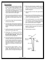
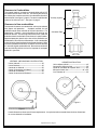
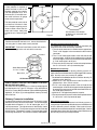
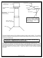
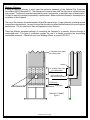
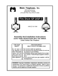
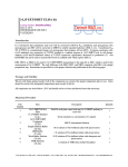
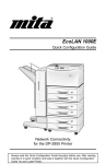
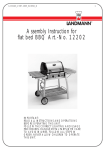
MALM FIREPLACES, INC.
Clearview Glass
ASSEMBLY AND INSTALLATION INSTRUCTIONS
Tested to U/L Standard 737
SAFETY NOTICE
If this fireplace is not properly installed, a house fire may result. To reduce the risk of fire, follow
the installation instructions. Contact local building or fire officials about restrictions and
installation inspection requirements in your area.
This stove must be connected to (1) a chimney complying with the requirements for Type HT
chimneys in the Standard for Chimneys, Factory-Built, Residential Type and Building Heating
Appliance, UL 103, or (2) a code-approved masonry chimney with a flue liner.
Please read this entire manual before you install and use your new fireplace. Failure to follow
instructions may result in property damage, bodily injury, or even death.
DO NOT INSTALL THIS UNIT IN A MOBILE HOME.
1. Carefully remove all components from the shipping cartons
and inspect for damage. If any damage is noted contact the
shipping company or your dealer immediately. DO NOT
INSTALL THIS UNIT IF DAMAGED OR MISSING PARTS.
2. Protect the flooring near the intended place of installation
with an old rug, blanket, or cardboard. Place the firebox on
this material.
3. Mix and install the Malmcrete hearth refractory as follows:
a. Obtain a sturdy water-tight mixing container such as a
wheelbarrow or large wash tub, a bucket or can for
transporting the mixture, a cement trowel, and a source for
clean mixing water. It is suggested that the Malmcrete be
mixed outside to avoid spillage or splatters in the dwelling.
b. Pour the dry Malmcrete mixture into the mixing container.
c. Use 1 quart water for each bag.
d. Add 1/2 to 3/4 of the water to the dry mix and mix thourghly.
Add additional water in small increments, mixing
throughly between additions. Do not add more water than
is necessary to get a somewhat dry mixture; to much
water in the mix may cause the refractory to crack excessively, and will reduce the strength of the refractory. To
test for proper water content, cut vertically into the mixture
with the trowel, push the trowel sideways to open a 3 inch
deep by 2 inch wide cut in the mixture, then slide the trowel
back up out of the cut. The cut should stay open with very
little "slumping" back into the cut. Next, run the trowel over
the surface of the mixture with the blade at a slight angle
to the surface of the mixture, like spreading butter. The
mixture should become relatively smooth with few voids
after 6 or 7 passes of the trowel using moderate
pressure. Water should not float to the top of the
mixture.
e. Transfer the mixture to the hearth (floor) area inside the
firebox, spreading the mixture out as it is added. Use the
trowel to spread the mix into the firebox area. Continue
to add refractory until there is a minimum of 2 inches thick
over the entire hearth area. To measure the depth of the
mix, place a piece of tape 2 inches from the pointed end
of a long nail. Insert the nail vertically through the mix
every 6 inches
(front to back and
side to side) across
the hearth; the mix
Refractory
should come to a
2"
uniform height up
the nail, at or slightly
above the tape.
Trowel in the nail holes when completed.
Shape the refractory to the contour of the Imperial hearth.
If the refractory will not stay in place wait untill the
refractory has set slightly. Check the refractory every few
minutes to see if it has set enough to stay in place.
f. Allow the mix to cure at least 48 hours. Additional curing
time is necessary in cool temperatures. The longer
Malmcrete is allowed to cure before the first fire is lit, the
stronger and more durable it will become.
g. Make the first 3 or 4 fires very small and of short duration
to allow the refractory to adjust to the high temperature
of a fire.
Glass Installation
Wear eye protection during the assembly of
this unit. Check all glass and parts for damage. Replace any damaged parts prior to
continuing the installation. Do not assemble
this unit with any damaged parts. If you
should happen to break a glass panel, it must
only be replaced with ceramic glass.
8. Slide the gasketed edge completely into the
channel on the side of the door. The left edge of
the glass should now fit into the button at the
bottom of the glass.
1. The door panel has had the latch assembly
and hinges installed at the factory. Remove
the hinges leaving the glued on plate in position.
10. Repeat steps 8 and 9 with the right door panel.
The gasket will be on the left side of the panel
with the not polished edge at the top.
2. Place the lower hinge in the hole in the firebowl,
with the washer under it.
11. The remaining panels can now be installed.
The edge that is not polished is placed at the
top. As each panel is installed replace the
glass retainer in place but do not tighten.
3. Insert the upper hinge into the hole at the top
of the door opening. Holding the upper hinge
in place, slide the glass door panel into the
hinges.
4. Hold the door panel in the closed position to
allow access to the hinge screws.
9. Lower the glass into the lower glass button
channel.
12. After all the glass panels are installed center the
panels to reduce any gaps that may be between the glass panels.
13. Tighten the glass retainers.
5. Maintaining a 1/8" clearance to the left door
post, tighten the screws in the hinges snugly.
DO NOT OVER TIGHTEN. Re-adjust as
necessary for proper alignment.
6. Note that two panels have gasket material on
one edge. These pieces go on either side of
the door. Make certain that these two pieces
are placed completly into the channel on
either side of the door. Failure to do this will
make the rest of the glass installation impossible.
Hood
Retainer
and Screw
7. First loosen the glass retainers. This is a
metal strip secured by one screw in the
middle. Start with the left door panel. The
gasket must be on the right side of the panel.
Imperial Carousel - Page 2
Glass
Lower Glass
Button
Upper
Glass
Channel
Clearance to Combustibles
The Imperial requires a clearance to combustible walls of 42"
measured from the back of the unit. For locating the center of
the chimney the measurement is 63" from the backwall and 63"
to the sidewall. See figure 1, page 2. For corner installation the
center of the chimney is 63". See figure 2, page 2.
Chimney System
Clearance to Non-combustibles
The Imperial clearance to a combustible wall may be reduced
with proper wall protection.
Accepted methods for wall
protection would allow reduction of the wall clearances. For
appearance if desired a non-combustible wall covering can
placed on the wall. The covering should consist of a listed wall
protection board installed to the manufacturer's specifications.
Approved protection boards at the time of this publication are
Wonderboard, Dura Rock and Homosote. A non-combustible
material can then be placed over the wall protection board. With
most of the protection boards the clearance can be reducedby
2/3 from the original combustible wall. Be certain to check with
your local building officials and or fire inspector for accepted
methods in your area.
SIDEWALL AND BACKWALL INSTALLATION
Unit to Sidewall ----------------------------------------- 42"
Unit to Backwall ---------------------------------------- 42"
Connector to Sidewall -------------------------------- 58"
Center of Connector to Sidewall ------------------- 63"
Connector to Backwall ------------------------------- 58"
Center of connector to Backwall ------------------- 63"
Connector Pipe
Unit
CORNER INSTALLATION
Unit to Adjacent Walll --------------------------------- 42"
Connector to Adjacent Wall ------------------------- 58"
Center of Connector to Adjacent Wall ------------ 63"
Minimum Hearth Size ------------------------- 48" x 54"
Or a Diameter of --------------------------------------- 54"
58"
42"
58"
42"
Figure 2.
Figure 1.
Hearth dimensions shown are minimum requirements. It may be desired to exceede these minimum dimensions
for a more decorative installation.
Imperial Carousel - Page 3
Hearth Requirements
A floor protector is required to
protect the floor in front of the
fireplace opening from sparks.
The floor protector must be a
minimum of 2 1/2 inch thick common solid brick over 26 gauge
sheet metal or equivalent.
The floor protector must extend
a minimum of 16 inches in front
of the fireplace opening and 8
inches to either side of the fireplace and 8 inches behind the
back of the unit. Refer to Figure
#3.
48"
16" From Door
16"
8"
Door
Fire Bowl
54"
8"
8"
8"
8"
8"
Figure 3
54" Diameter Circle Hearth.
8" Minimum is measured from
the fire-box
Hood Assembly
Position the hood on the basic unit. Secure hood to basic
unit using the 13 sheet metal screws provided.
IMPORTANT: Failure to install these screws will result in
permanet damage to the unit and void the warranty.
Hood
Sheet Metal Screws
13- 14 x 1/2 Hex.
Basic Unit
All Screws Must Be Installed
DO NOT CONNECT THIS UNIT TO A CHIMNEY FLUE SERVING ANOTHER APPLIANCE.
This stove must be connected to (1) a chimney complying with
the requirements for Type HT chimneys in the Standard for
Chimneys, Factory-Built, Residential Type and Building Heating
Appliance, UL 103, or (2) a code-approved masonry chimney
with a flue liner.
Chimney Connector Installation
It is required to install a 8 inch all-fuel class "A" chimney system
prior to the chimney connector installation. The connector pipe
included with the Imperial is 1 - 8" x 30" starter pipe, and 1 - 8"
x 30" slip connector. The slip connector is identified by 3 holes
at the top of the pipe. The slip connector has one flair at the top
with the 3 holes. The bottom is smooth. The starter pipe section
has flairings at both ends. The male end is always at the bottom.
Simpson Dura-Vent Chimney System
It is required to use a Dura-Vent Universal Connector part
number 8874 to install the chimney connector.
1. The universal connector is installed into the support box.
The 8" x 30" slip pipe is then connected to the universal
connector.
2. The 8" x 30" starter pipe section is then slid over the slip
connector pipe. Slide the 30 inch pipe over the slip pipe
only far enough as necessary to facilitate installation of the
8" x 30" starter pipe in to the unit.
3. There must be a minimum of 2 inches of overlap between
the 8" x 30" and 8" x 30" slip connector pipe.
Metalbestos or Security
When using Metalbestos or Security chimney systems it is
required to use the Metalbestos DS-CPA Single Wall Conector
pipe. Security users must use the UP adapter.
1.Installation of the Metalbestos DS-CPA or the Security UP
adapter must be done first.
2.Attach the 8" x 30" slip connector to the DS-CPA or UP
adapter with 3 - #8 x 3/8 inch screws.
3.The 8" x 30" starter pipe section is then slid into the slip
connector pipe. Slide the 30 inch pipe into the slip pipe only
far enough as necessary to facilitate installation of the 8" x
30" starter pipe into the unit.
4.Slide the 8" x 30" pipe down onto the Imperial.
5.There must be a minimum of 2 inches of overlap between the
8" x 30" and 8" x 30" slip connector pipe.
Other Chimney Systems
There are many other manufacturer's of chimney systems. It
is beyond the scope of this publication to cover installation with
all of the different systems available. Most systems have a
method of connection to the Imperial's connector pipe. Confirm
installation procedures with your dealer or the manufacturer of
the chimney system you have purchased.
Imperial Carousel - Page 4
Insulated Class "A"
Chimney System
Insulated Pipe
Ceiling
Single Wall Chimney
Adapter
Support Box
Sheet Metal
Screw
Slip Connector
Slip Connector. Sheet
Metal Screw to
Chimney Connector.
Dura-Vent Universal Adapter,
Security UP Adapter, Metalbestos DS-CPA ,Or Single Wall
Chimney Adapter
Starter Section Fits
Into Hood
Hood
The above illustration represents the installation procedure for dripless pipe installation. This installation
method of installing the connector pipe with the male end down allows for any moisture to remain on the
inside of the connector pipe.
IMPORTANT: THE SINGLE WALL CONNECTOR PIPE MUST NEVER PASS
THROUGH A COMBUSTIBLE CEILING OR WALL.
At first glance you may become concerned that smoke will escape the pipe and enter the room. This is
not how the system will work. The vacum in the chimney system will always pull air into the chimney. If
you experience a downdraft with your installation it indicates that additional chimney height or a specialty
draft cap be added to your chimney system. Contact your dealer for further information regarding
downdrafts.
Imperial Carousel - Page 5
Masonry Chimney
If using a masonry chimney, it must meet the minimum standards of the National Fire Protection
Association (NFPA) Standard 211. The chimney must have at least a 5/8" fire clay liner or a listed chimney
liner system. The chimney must be inspected for cracks, loose mortar, or any other signs of deterioration.
It is best to have the chimney inspected by a professional. Make certain the chimney is cleaned prior to
installation of this fireplace.
The size of the chimney should be between 36 and 96 square inches. Larger chimneys should be relined
to meet these requirements. Incorrect sizing of the chimney may affect the draft and result in poor fireplace
performance. Do not install more than one appliance to any chimney.
There are different accepted methods of connecting the fireplace to a masonry chimney through a
combustible wall. This type of installation requires the use of a thimble to protect the surrounding
combustible materials. Check with your local building officials or consult NFPA211.
2" Clearance From Studs
To Chimney Wall
Header
12" Of Brick From Liner
To Combustibles
5/8" Fireclay Liner
Minimum or Equivalent
12" Minimum
Sill/Support
12" Minimum
MASONRY THIMBLE
Figure 4
Imperial Carousel - Page 6
OPERATING INSTRUCTIONS
Failure to properly use and maintain this appliance may void the
manufacturer's warranty and could result in a house fire.
WARNING: This free standing fireplace is a heat
producing appliance and may cause severe burns if
touched. Keep children away. Do Not over fire. If any
portion of the unit or flue starts to glow you are over
firing. This is a free standing fireplace, do not use for
any other purpose.
1. The first few fires should be small in order to
properly cure the painted surfaces and refractory.
During the first few fires, some smoking may occur
as the paint cures. You may wish to open a
window to minimize discomfort during this curing
period.
2. DO NOT BURN TRASH OR GARBAGE IN THIS
UNIT. When building a fire, be sure the damper is
fully opened and sufficient combustion air is available. Place dry kindling on dry wadded paper
then ignite with a match. Add progressively larger
pieces of wood until the fire is well established.
Leave the damper fully open. Close only after the
fire has burned out completely. Add additional
firewood as needed to maintain the fire.
3. The fire screen must be in place during operations. THIS FIREPLACE STOVE HAS NOT BEEN
TESTED FOR USE WITH DOORS. TO REDUCE
THE RISK OF FIRE OR INJURY, DO NOT INSTALL DOORS.
4. DO NOT ELEVATE THE FIRE. A grate should
not be used.
5. CAUTION: Heating the air in a closed building
decreases the relative humidity of the air, which
will dry wood and other combustible materials.
This drying lowers the ignition temperature of
these materials thus increasing fire hazards. To
reduce the risk of fire, some provision should be
made for replenishing moisture to the air whenever a structure is being heated for extended
periods.
6. Be sure to provide combustion air into the dwelling
when using this or any other wood burning appliance. A partially open window or outside air
register in the vicinity of the unit would be acceptable. Combustion air must be supplied in conformance with the Uniform Mechanical Code.
7. CAUTION: NEVER USE GASOLINE, GASOLINE
TYPE LANTERN FUEL, KEROSENE, CHARCOAL LIGHTER FLUID, OR SIMILAR LIQUIDS
TO START OR “FRESHEN UP” A FIRE IN THIS
HEATER. KEEP ALL SUCH LIQUIDS WELL
AWAY FROM THE HEATER WHILE IN USE.
8. DISPOSAL OF ASHES: Ashes should be placed
in a metal container with a tight fitting lid. The
closed container of ashes should be placed on a
noncombustible floor or on the ground, away from
all combustible materials, pending final disposal.
The ashes should be retained in the closed container until all cinders have thoroughly cooled.
9. READ MAINTENANCE INSTRUCTIONS.
IN CASE OF A CHIMNEY FIRE
A safe and correct installation and extra care will help
prevent a fire, but accept the idea that there could be
a fire. Be prepared to handle it. Make certain
everyone in the house is familiar with the warning
signs of a chimney fire:
1. Call the Fire Department immediately, before doing anything else.
2. Discharge a dry chemical extinguisher into the
fireplace opening. If an extinguisher is not available, toss baking soda into the opening. Do not
pour water on the fire.
3. Close all air intakes to the firebox and leave closed
until the fireplace, stove or stove pipe is completely cooled.
4. Watch for sparks on the roof. If necessary, hose
down the roof around the chimney.
DO NOT pour water down or on the chimney.
5. After the fire is completely out, inspect the chimney for any signs of damage. If you are not
certain, have your local Fire Department inspect
the chimney for you. Never use a flammable liquid
to kindle or rekindle a fire.
6. Never use coal in a fireplace. Coal should be used
only in stoves especially designed to burn coal. If
the toxic gases produced enter the room they can
be fatal.
Imperial Carousel - Page 7
MAINTENANCE INSTRUCTIONS
Failure to properly use and maintain this appliance may void the
manufacturer's warranty and could result in a house fire.
1.Always keep the area around the unit clean and clear of
furniture and other objects. Keep all furniture a minimum
of 48 inches away from the heater.
2.Periodically the entire unit, chimney connector, and chimney system must be inspected for leaks, broken or malfunctioning parts, and loose connections. If any problems
are noted, contact your dealer for repair services. Do not
operate the unit until repairs have been completed.
CREOSOTE FORMATION AND THE NEED FOR
REMOVAL.
When wood is burned slowly, it produces tar and other
vapors, which combine with moisture to form creosote.
Creosote vapors condense in the relatively cool chimney
flue, and creosote residue accumulates on the flue lining.
When ignited, this creosote can make an extremely hot
fire. The chimney connector and chimney should be
inspected at least twice monthly during the heating season
to determine if creosote buildup has occurred. If creosote
has accumulated, it should be removed to reduce the
chance of a chimney fire.
HOW TO REMOVE CREOSOTE.
1.Clean the chimney with brushes and equipment available
at local fireplace shops.
2.Chemical chimney cleaners are used by adding them to
the fire, but they are not intended for use in chimneys
already containing heavy soot deposits. Rather, they are
intended to inhibit soot buildup. They can be used in metal
chimneys provided the manufacturers instructions are
strictly followed. Generally these commercial cleaners
are quite effective.
3.Call a professional chimney sweep in your area. They
possess the experience and tools necessary to make the
task easy.
Maintenance other than the items specifically mentioned
herein are to be performed by a qualified serviceman only.
Contact your dealer. For further information on using your
heater safely, obtain a copy of the National Fire Protection
Association publication "Using Coal and Wood Stoves
Safely," NFPA HS-10-1978. The address of the NFPA is
Batterymarch Park, Quincy, MA 02269. File these instructions for future reference.
NEVER STORE OR ALLOW PAPERS,
KINDLING, FIREWOOD OR ANY
OTHER COMBUSTIBLES WITHIN 48
INCHES OF UNIT.
MALM FIREPLACES, INC.
368 YOLANDA AVENUE
SANTA ROSA, CALIFORNIA 95404
(707) 523-7755
FAX: (707) 571-8036
[email protected]
June 1992
Imperial Carousel - Page 8