1
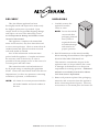
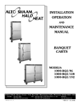
Banquet Carts Electric Models: 1 000-BQ2/96 1000-BQ2/128 1000-BQ2/192 1000-BQ2/96 1000-BQ2/128 • INSTALLATION • OPERATION • MAINTENANCE 1000-BQ2/192 W164 N9221 Water Street • P.O. Box 450 • Menomonee Falls, Wisconsin 53052-0450 USA PHONE: 262.251.3800• 800.558.8744 USA / CANADA FAX:262.251.7067•800.329.8744 U . S . A . www.alto-shaam.com printed in u.s.a. ONLY MN-29578 • 01/12 Delivery . . . . . . . . . . . . . . . . . . . . . . . . . . . . . . . . . . . . . . . 1 Unpacking . . . . . . . . . . . . . . . . . . . . . . . . . . . . . . . . . . . . . 1 Safety Procedures and Precautions. . . . . . . . . . . . . . . . . . 2 Installation Site Installation. . . . . . . . . . . . Clearance Requirements. . . . . Dimension Drawings, weights Options and Accessories. . . . . Electrical Specifications . . . . . . . . . . . . . . . . . . . . . . . . . & capacities. . . . . . . . . . . . . . . . . . . . . . . . . . . . . . . . . . . . . . . . . . . . . . . . . . . . . . . . . . . . . . . . . . 3 3 4 5 6 Operating Instructions Start-Up . . . . . . . . . . . . . . . . . . . . . . . . . . . . . . . . . . . . 7 Holding Procedures. . . . . . . . . . . . . . . . . . . . . . . . . . . . 8 General Holding Guidelines. . . . . . . . . . . . . . . . . . . . . . 9 Care and Cleaning Cleaning and Preventative Maintenance. . Protecting Stainless Steel Surfaces. . . . . . Cleaning Agents . . . . . . . . . . . . . . . . . . . . Cleaning Materials . . . . . . . . . . . . . . . . . . Clean Daily. . . . . . . . . . . . . . . . . . . . . . . . . . . . . . . . . . . . . . . . . . . . . . . . . . . . . . . . . . . . . . . . . . . . . 10 10 10 10 11 Sanitation Sanitation/Food Safety . . . . . . . . . . . . . . . . . . . . . . . . 12 Service Thermostat Accuracy . Trouble Shooting. . . . . Cable Heating Kits . . . Service Parts List . . . . Service Views. . . . . . . . . . . . . . . . . . . . . . . . . . . . . . . . . . . . . . . . . . . . . . . . . . . . . . . . . . . . . . . . . . . . . . . . . . . . . . . . . . . . . . . . . . . . . . . . . . . . . . . . . . . . . . . . . . . . . . . . . . . . . . . 13 14 15 16 17 Wire Diagrams Always refer to the wire diagram(s) included with the unit for most current version. Warranty Transportation Damage and Claims . . . . . . . Back Cover Limited Warranty. . . . . . . . . . . . . . . . . . . . . . Back Cover DELIVERY UNPACKING This Alto-Shaam appliance has been thoroughly tested and inspected to ensure only the highest quality unit is provided. Upon receipt, check for any possible shipping damage and report it at once to the delivering carrier. See Transportation Damage and Claims section located in this manual. This appliance, complete with unattached items and accessories, may have been delivered in one or more packages. Check to ensure that all standard items and options have been received with each model as ordered. Save all the information and instructions packed with the appliance. Complete and return the warranty card to the factory as soon as possible to ensure prompt service in the event of a warranty parts and labor claim. This manual must be read and understood by all people using or installing the equipment model. Contact the Alto-Shaam Tech Team Service Department if you have any questions concerning installation, operation, or maintenance. 1. Carefully remove the appliance from the carton or crate. NOTE: All claims for warranty must include the full model number and serial number of the unit. 1000-BQ2 ® ® NOTE: Do not discard the carton and other packaging material until you have inspected the unit for hidden damage and tested it for proper operation. 2. Read all instructions in this manual carefully before initiating the installation of this appliance. DO NOT DISCARD THIS MANUAL. This manual is considered to be part of the appliance and is to be provided to the owner or manager of the business or to the person responsible for training operators. Additional manuals are available from the Alto-Shaam Tech Team Service Department. 3. Remove all protective plastic film, packaging materials, and accessories from the appliance before connecting electrical power. Store any accessories in a convenient place for future use. series operation & care manual • 1 SAFETY PROCEDURES AND PRECAUTIONS Knowledge of proper procedures is essential to the safe operation of electrically and/or gas energized equipment. In accordance with generally accepted product safety labeling guidelines for potential hazards, the following signal words and symbols may be used throughout this manual. 1. This appliance is intended to cook, hold or process foods for the purpose of human consumption. No other use for this appliance is authorized or recommended. 2. This appliance is intended for use in commercial establishments where all operators are familiar with the purpose, limitations, and DANGER associated hazards of this appliance. Operating Used to indicate the presence of a hazard that WILL cause severe personal injury, death, or substantial property damage if the warning included with this symbol is ignored. WARNING instructions and warnings must be read and understood by all operators and users. 3. Any troubleshooting guides, component views, and parts lists included in this manual are for general reference only and are intended for use by qualified technical personnel. 4. Thismanualshouldbeconsideredapermanent part of this appliance. This manual and all supplied instructions, diagrams, schematics, Used to indicate the presence of a hazard that CAN cause personal injury, possible death, or major property damage if the warning included with this symbol is ignored. parts lists, notices, and labels must remain with the appliance if the item is sold or moved to another location. CAUTION NOTE Used to indicate the presence of a hazard that can or will cause minor or moderate personal injury or property damage if the warning included with this symbol is ignored. For equipment delivered for use in any location regulated by the following directive: DO NOT DISPOSE OF ELECTRICAL OR ELECTRONIC EQUIPMENT WITH OTHER MUNICIPAL WASTE. CAUTION Used to indicate the presence of a hazard that can or will cause minor personal injury, property damage, or a potential unsafe practice if the warning included with this symbol is ignored. N O T E : Used to notify personnel of installation, operation, or maintenance information that is important but not hazard related. 1000-BQ2 series operation & care manual • 2 INSTALLATION SITE INSTALLATION This appliance, complete with unattached items and accessories, may be delivered in one or more packages, Check to insure that all the following items have been received as standard with each unit: Item BQ2/96 BQ2/128 BQ2/192 Shelves 4 4 8 Shelf Clips 4 4 8 Shelf Slides 8 8 16 DANGER IMPROPER INSTALLATION, ALTERATION, ADJUSTMENT, SERVICE, OR MAINTENANCE COULD RESULT IN SEVERE INJURY, DEATH, OR CAUSE PROPERTY DAMAGE. READ THE INSTALLATION, OPERATING AND MAINTENANCE INSTRUCTIONS THOROUGHLY BEFORE INSTALLING OR SERVICING THIS EQUIPMENT. This appliance is designed for the purpose of maintaining hot food at a temperature for safe consumption. It must be used on a level surface in a location that will permit the the banquet cart to function for its intended purpose and allow adequate access for proper cleaning and maintenance. CAUTION TO PREVENT PERSONAL INJURY, The unit must not be installed in any area where it may be affected by steam, grease, dripping water, high temperatures, or any other severely adverse conditions. WEIGHT • 1000-BQ2/96 net ship USE CAUTION WHEN MOVING OR LEVELING THIS APPLIANCE. CLEA R A NCE R EQ UIR EM ENTS contact factory 400 lbs (181 kg) Full perimeter bumper accommodates all clearance requirements. series operation & WEIGHT • 1000-BQ2/128 net contact factory ship contact factory WEIGHT • 1000-BQ2/192 net contact factory ship 690 lbs (313 kg) 1000-BQ2 care manual • 3 INSTALLATION SITE INSTALLATION 37-15/16" (964mm) 64-1/2" (1638mm) 7-9/16" (192mm) 67-5/8" (1716mm) 48-5/16" (1226mm) *International - 29-1/8" (739mm) 59-5/8" (1514mm) 30-13/16" (783mm)* CORD LENGTH 120V - 60" (1525mm) 208-240V - 96" (2438mm) 230V - 96" (2438mm) 1000-BQ2/96 Max. Load Capacity 240 lbs. (109 kg) 240 qts. (304 lt) 22-5/16" (565mm) 27-5/8" (701mm) 45-13/16" (1164mm) 64-1/2" (1638mm) 48-5/16" (1226mm) 7-9/16" (192mm) 67-5/8" (1716mm) *International - 29-1/8" (739mm) 59-5/8" (1514mm) 30-13/19" (783mm)* CORD LENGTH 120V - 60" (1525mm) 208-240V - 96" (2438mm) 230V - 96" (2438mm) 1000-BQ2/128 Max. Load Capacity 320 lbs. (145 kg) 240 qts. (304 lt) 35-1/2" (901mm) 22-5/16" (565mm) 68-11/16" (1744mm) 64-13/16" (1646mm) 67-5/8" (1716mm) 48-5/16" (1226mm) 7-9/16" (192mm) *International - 29-1/8" (739mm) 59-7/16" (1509mm) 30-13/16" (783mm)* CORD LENGTH 120V - 72" (1829mm) 208-240V - 96" (2438mm) 230V - 96" (2438mm) 1000-BQ2/192 22-5/16" (565mm) 57-1/2" (1459mm) Max. Load Capacity 480 lbs. (218 kg) 480 qts. (608 lt) 1000-BQ2 series operation & care manual • 4 INSTALLATION Options and Accessories Plate Carriers, Chrome Plated ( each holds four (4) preplated 1000-BQ2/96 Capacity meals ) Uncovered “P” Carriers Plate Diameter: Max. 10" (254mm) Min. 7-3/4" (197mm) Vertical rung spacing: 2-5/8" (67mm) 1000-BQ2/128 Capacity 1000-BQ2/192 Capacity DC-2868 DC-2868 DC-2868 24 carriers 32 carriers 48 carriers 96 preplated meals 128 preplated meals 192 preplated meals Covered “C” Carriers DC-2869 DC-2869 DC-2869 Plate Diameter: Max. 9-3/4" (248mm) Min. 7-3/4" (197mm) 24 carriers 32 carriers 48 carriers Vertical clearance between top and bottom carrier: 11-5/8" (295mm) 96 preplated meals 128 preplated meals 192 preplated meals Uncovered “EP” Carriers Plate Diameter: Max. 12-1/2" (318mm) Min. 9-1/2" (241mm) Vertical rung spacing: 2-5/8" (67mm) DC-23580 DC-23580 DC-23580 16 carriers 24 carriers 32 carriers 64 preplated meals 96 preplated meals 128 preplated meals Covered “EC” Carriers DC-23676 DC-23676 DC-23676 Plate Diameter: Max. 12-1/2" (318mm) Min. 9-1/2" (241mm) 16 carriers 24 carriers 32 carriers Vertical clearance between top and bottom carrier: 11-5/8" (295mm) 64 preplated meals 96 preplated meals 128 preplated meals Shelf Support (2 req’d for each shelf) 1061 1061 1061 Shelf Support Clip (1 req’d for each shelf) 11533 11533 11533 Wire Shelf, Chrome Plated SH-2835 SH-22727 SH-2835 Door Lock with Key LK-22567 LK-22567 LK-22567 5013816 5013816 5013816 Security Devices - includes tamper-proof screws, control panel security cover, and door lock Plate Capacity (16 plates high, 3" plate height) 8" - 8-3/4" 176 Plates 8" - 8-3/4" 256 Plates 8" - 8-3/4" 128 Plates 9" - 10" 128 Plates 9" - 10" 192 Plates 9" - 10" 96 Plates 10-1/4" - 12-3/4" 96 Plates 10-1/4" - 12-3/4" 128 Plates 10-1/4" - 12-3/4" 64 Plates 12" - 12-3/4" 64 Plates BQ2-96 BQ2-192 BQ2-128 1000-BQ2 series operation & care manual • 5 INSTALLATION ELECTRICAL CONNECTION DANGER DANGER ELECTRICAL CONNECTIONS MUST BE MADE BY A QUALIFIED SERVICE TECHNICIAN IN ACCORDANCE WITH APPLICABLE ELECTRICAL CODES. ENSURE POWER SOURCE MATCHES VOLTAGE STAMPED ON APPLIANCE NAMEPLATE. DANGER 1. A n identification tag is permanently mounted on the cabinet. To avoid electrical shock, this appliance MUST be adequately grounded in accordance with local electrical codes or, in the absence of local codes, with the current edition of the National Electrical Code ANSI/ NFPA No. 70. In Canada, all electrical connections are to be made in accordance with CSA C22.1, Canadian Electrical Code Part 1 or local codes. 2.P lug cabinet into a properly grounded receptacle ONLY, positioning the unit so the power supply cord is easily accessible in case of an emergency. 3. I f necessary, a proper receptacle or outlet configuration as required for this unit, must be installed by a licensed electrician in accordance with applicable, local electrical codes. NOTE: CE approved appliances must be connected to an electrical circuit that is protected by an external GFCI outlet. For CE approved units: To prevent an electrical shock hazard between the appliance and other appliances or metal parts in close vicinity, an equalization-bonding stud is provided. An equalization bonding lead must be connected to this stud and the other appliances / metal parts to provide sufficient protection against potential difference. The terminal is marked with the following symbol. ELECTRICAL • 1000-BQ2/96 voltage phase cycle/hz amps kW Hard wired models must be equipped with a country certified external allpole disconnection switch with sufficient contact separation. If a power cord is used for the connection of the productanoilresistantcordlikeH05RNorH07RN or equivalent must be used. & plug included 5-15p 15A- 125V plug 208-240 (agcy)1 at 208 1 at 240 1 nema 6-15p 15A - 250V plug 60 60 60 7.0 5.9 6.8 1.6 1.2 1.6 230 (agcy) 1 50/60 6.5 1.5 nema cee 7/7 220-230V plug ELECTRICAL • 1000-BQ2/128 voltage phase cycle/hz ampskW 120 (agcy) 1 60 17.5 2.1 Hard wired models: cord 120 (agcy)1 60 12.51.5 208-240 (agcy)1 60 8.8 2.1 208 1 60 7.7 1.6 240 1 60 8.9 2.1 230 (agcy) 1 50/60 8.4 2.0 cord & plug included nema 5-20p 20A- 125V plug nema 6-15p 15A - 250V plug cee 7/7 220-230V plug ELECTRICAL • 1000-BQ2/192 voltage phase 120 (agcy) 1 cycle/hz ampskW 60 24.0 2.9 power switch in low position 16.0 1.9 power switch in high position 25.0 max 3.0 208-240 (agcy)1 at 208 1 at 240 1 60 60 60 13.5 11.8 13.6 3.3 2.5 3.3 230 (agcy) 1 50/6013.0 3.0 cord & plug included 5-20p 20A- 125V plug nema 5-30p 30A - 125V plug nema nema 6-15p 15A - 250V plug cee 7/7 220-230V plug Wire diagrams are located inside the top of the unit. 1000-BQ2 series operation & care manual • 6 OPERATION OPERATING INSTRUCTIONS Heat Indicator Light 4. L oad the cabinet with hot food only. The purpose of the holding cabinet is to maintain hot food at proper serving temperatures. Only hot food should be placed into the cabinet. Before loading the unit with food, use a food thermometer to make certain all food products I are at an internal temperature range of 140° to 160°F (60° to 71°C). All food not within the proper temperature range should be heated before loading into the o holding cabinet. Digital Display I o On/Off Power Switch Temperature Display Key Up/Down Arrow Keys 1. P REHEAT AT 200°F (93°C) FOR 30 MINUTES BEFORE LOADING FOOD. 5. C heck to make certain the cabinet door is securely closed, and using the Up and Down Arrow Keys, set the temperature to 160°F (71°C). THIS WILL NOT NECESSARILY BE THE FINAL SETTING. Push power switch to “ON” position. The unit will begin operating at the previous set temperature. The proper temperature range for the food being held will depend on the type and quantity of product. Whether or not the door vents should be open or closed will also depend on the type of food being held. When holding food for prolonged periods, it is advisable to periodically check the internal temperature of each item to assure maintenance of the proper temperature range. Reset the holding temperature accordingly. 2. Press the Up or Down Arrow Keys to 200°F (93°C). Pressing and releasing the Arrow Keys will increase the set point by 1 degree. Pressing and holding the Arrow Key will increase set point by 10 degrees. When Arrow Key is released, a new set point temperature is set. The Set temperature will appear in the Digital Display and the Heat Indicator Light will illuminate. Press the Temperature Display Key for three seconds at any time to display the Actual inside air temperature. Press the Temperature Display Key at any time to display the alternate temperature. The factory default is Fahrenheit. To change to Celsius: To toggle between Set and Actual: Factory default is to display Set temperature in the Digital Display. To display Actual temperature: Press and hold the Temperature Display Key and the Up Arrow Key for 5 seconds. The control will show ACT , then show the Actual temperature. Repeat to toggle to Set point SET . Press the Temperature Display Key at any time to display the alternate temperature. 3. W hen the inside air temperature reaches the desired holding temperature, the Heat Indicator Light will turn off. 1000-BQ2 TO TOGGLE BETWEEN FAHRENHEIT AND CELSIUS 1. Press and hold the Temperature Display Key and the Down Arrow Key for 5 seconds. . 2. T he control will show for 3 seconds to verify C selection and then show the temperature. (Set Point or Actual, whichever the user has selected) in ºC. 3. Repeat to toggle to Fahrenheit. Note: With a power failure, factory test, etc., the control will retain the ºC or ºF setting selected by the user when power is restored. series operation & care manual • 7 OPERATING INSTRUCTIONS HOLDING PROCEDURE Heat Indicator Light C.Load the plates in the upper section of the banquet cart first. Digital Display D.Securely close the doors of the banquet cart after loading each series of plates. I E. When loading the upper section I of the banquet cart, the door on the lower section should remain closed. o On/Off Power Switch F. When loading the lower section o of the banquet cart, the door on the upper section should remain closed. Up/Down Arrow Keys Temperature Display Key 4.Reset the thermostat to desired temperature. After the cart has been completely filled with product, check to make certain the doors are securely closed, and reset the thermostat to to the desired holding temperature or the suggested 180°F (82°C). 1. Preheat at 200°F for 30 minutes. Allow a minimum of 30 minutes for preheating before loading the banquet cart with product. The proper temperature range for the products being held, and whether or not to open or close the door vents, will depend on the type and quantity of product. When holding food for prolonged periods, it is advisable to periodically check the internal temperature of each item with a food thermometer to assure maintenance of the proper temperature range of 140° to 160°F (60° to 71°C). 2. Load the cart with hot food only. The purpose of the banquet cart is to maintain hot food at proper serving temperature. Only hot food should be placed into the banquet cart. Before loading the cart with food, use a food thermometer to make certain all products have reached an internal temperature range of 140° to 160°F (60° to 71°C). Any food product not within the proper temperature range should be heated before loading into the banquet cart. For best results, use a Halo Heat Low Temperature Cooking and Holding Oven set at 250° to 275°F (121° to 135°C), or a Combitherm oven, to bring the product within the correct temperature range. 3.Load covered plates or carriers into the banquet cart. After the food has reached proper serving temperature: A.Unload the items from the lower section of the cart first, and work up toward the top of the cart. B. When unloading the lower section of the banquet cart, the door on the upper section should remain closed. C.When unloading the upper section of the cart, the door on the lower section should remain closed. A.Use HEATED plates only. B. Load each series of four (4) plates into the banquet cart as soon as assembled and as quickly as possible to retain maximum heat. 1000-BQ2 5.Unload covered plates, trays or plate carriers as needed. D.Securely close the doors of the cart after each product removal. series operation & care manual • 8 OPERATING INSTRUCTIONS General Holding Guideline Chefs, cooks and other specialized food service personnel employ varied methods of cooking. Proper holding temperatures for a specific food product must be based on the moisture content of the product, product density, volume, and proper serving temperatures. Safe holding temperatures must also be correlated with palatability in determining the length of holding time for a specific product. Halo Heat maintains the maximum amount of product moisture content without the addition of water, water vapor, or steam. Maintaining maximum natural product moisture preserves the natural flavor of the product and provides a more genuine taste. In addition to product moisture retention, the gentle properties of Halo Heat maintain a consistent temperature throughout the cabinet without the necessity of a heat distribution fan, thereby preventing further moisture loss due to evaporation or dehydration. When product is removed from a high temperature cooking environment for immediate transfer into equipment with the lower temperature required for hot food holding, condensation can form on the outside of the product and on the inside of plastic containers used in self-service applications. Allowing the product to release the initial steam and heat produced by high temperature cooking can alleviate this condition. To preserve the safety and quality of freshly cooked foods however, a maximum of 1 to 2 minutes must be the only time period allowed for the initial heat to be released from the product. HOLDING TEMPERATURE RANGE MEAT 1000-BQ2 CELSIUS 130°F 54°C BEEF ROAST — Med/Well Done 155°F 68°C BEEF BRISKET 160° — 175°F 71° — 79°C CORN BEEF 160° — 175°F 71° — 79°C PASTRAMI 160° — 175°F 71° — 79°C PRIME RIB — Rare STEAKS — Broiled/Fried 130°F 54°C 140° — 160°F 60° — 71°C RIBS — Beef or Pork 160°F 71°C VEAL 160° — 175°F 71° — 79°C HAM 160° — 175°F 71° — 79°C PORK 160° — 175°F 71° — 79°C LAMB 160° — 175°F 71° — 79°C CHICKEN — Fried/Baked 160° — 175°F 71° — 79°C DUCK 160° — 175°F 71° — 79°C TURKEY 160° — 175°F 71° — 79°C GENERAL 160° — 175°F 71° — 79°C POULTRY FISH/SEAFOOD FISH — Baked/Fried 160° — 175°F 71° — 79°C LOBSTER 160° — 175°F 71° — 79°C SHRIMP — Fried 160° — 175°F 71° — 79°C 120° — 140°F 49° — 60°C 160° — 175°F 71° — 79°C 80° — 100°F 27° — 38°C BAKED GOODS BREADS/ROLLS MISCELLANEOUS CASSEROLES DOUGH — Proofing Most Halo Heat holding equipment is provided with a thermostat control between 60° and 200°F (16° to 93°C). If the unit is equipped with vents, close the vents for moist holding and open the vents for crisp holding. If the unit is equipped with a thermostat indicating a range of between 1 and 10, use a metal-stemmed indicating thermometer to measure the internal temperature of the product(s) being held. Adjust the thermostat setting to achieve the best overall setting based on internal product temperature. FAHRENHEIT BEEF ROAST — Rare EGGS —Fried 150° — 160°F 66° — 71°C FROZEN ENTREES 160° — 175°F 71° — 79°C HORS D'OEUVRES 160° — 180°F 71° — 82°C PASTA 160° — 180°F 71° — 82°C PIZZA 160° — 180°F 71° — 82°C POTATOES PLATED MEALS 180°F 82°C 140° — 165°F 60°— 74°C 60° — 93°C SAUCES 140° — 200°F SOUP 140° — 200°F 60° — 93°C VEGETABLES 160° — 175°F 71° — 79°C THE HOLDING TEMPERATURES LISTED ARE SUGGESTED GUIDELINES ONLY . ALL FOOD HOLDING SHOULD BE BASED ON INTERNAL PRODUCT TEMPERATURES . ALWAYS FOLLOW LOCAL HEALTH TEMPERATURE REQUIREMENTS . series operation & care manual • 9 ( HYGIENE ) REGULATIONS FOR ALL INTERNAL CARE AND CLEANING CLEANING AND PREVENTIVE MAINTENANCE PROTECTING STAINLESS STEEL SURFACES CLEANING AGENTS It is important to guard against corrosion in the care of stainless steel surfaces. Harsh, corrosive, or inappropriate chemicals can completely destroy the protective surface layer of stainless steel. Abrasive pads, steel wool, or metal implements will abrade surfaces causing damage to this protective coating and will eventually result in areas of corrosion. Even water, particularly hard water that contains high to moderate concentrations of chloride, will cause oxidation and pitting that result in rust and corrosion. In addition, many acidic spills left to remain on metal surfaces are contributing factors that will corrode surfaces. Use non-abrasive cleaning products designed for use on stainless steel surfaces. Cleaning agents must be chloridefree compounds and must not contain quaternary salts. Neverusehydrochloricacid(muriaticacid)onstainless steel surfaces. Always use the proper cleaning agent at themanufacturer’srecommendedstrength.Contactyour local cleaning supplier for product recommendations. Proper cleaning agents, materials, and methods are vital to maintaining the appearance and life of this appliance. Spilled items should be removed and the area wiped as soon as possible but at the very least, a minimum of once a day. Always thoroughly rinse surfaces after using a cleaning agent and wipe standing water as quickly as possible after rinsing. PREVENTATIVE MAINTENANCE 1. Ensure that the correct Operation and Care Manual is available to all users. 2. Ensure that all users have been properly trained in unit’soperation. 3. Donotexceedtheunit’scapacity. 4. Inspect condition of plug and cord. Replace if damaged. 5. Clean dust from outer vents surrounding the unit. 6. Check door gasket integrity. Are there any tears? Is the CLEANING MATERIALS The cleaning function can usually be accomplished with the proper cleaning agent and a soft, clean cloth. When more aggressive methods must be employed, use a non-abrasive scouringpadondifficultareasand make certain to scrub with the visible grain of surface metal to avoid surface scratches. Never use wire brushes, metal scouring pads, or scrapers to remove residue. 9. Check control panel overlay condition. Are there any tears or excessive wear on the graphic? Does the control work properly when buttons are pushed? 10. Check that all control LEDs light up as applicable. 11. Is the Set Temperature comparable to the Actual temperature displayed? If not, control needs calibration. Call Service. Contact Service for immediate repair if any of the above problems exist. CAUTION gasket worn or loose? Make sure seal is tight to unit body. Replace gasket if integrity is compromised. 7. Check air temperature sensor mount on the interior of RS NO chamber. Is the metal guard in place? Are the wires in good condition? RA PE SC 8. Check caster or leg condition. Ensure mounting bolts and assembly is secure. NO series operation & S ST E EL P A DS 1000-BQ2 BRU S NO IR E HE W TO PROTECT STAINLESS STEEL SURFACES, COMPLETELY AVOID THE USE OF ABRASIVE CLEANING COMPOUNDS, CHLORIDE BASED CLEANERS, OR CLEANERS CONTAINING QUATERNARY SALTS. NEVER USE HYDROCHLORIC ACID (MURIATIC ACID) ON STAINLESS STEEL. NEVER USE WIRE BRUSHES, METAL SCOURING PADS OR SCRAPERS. care manual • 10 CARE AND CLEANING The cleanliness and appearance of this unit will contribute considerably to operating efficiency and savory, appetizing food. Good equipment kept clean works better and lasts longer. 1. D isconnect unit from power source, and let cool. 2. R emove all detachable items such as plate carriers, shelves and side racks. Clean these items separately with a good grease solvent or commercial detergent. Rinse well and dry. 3. C lean interior metal surfaces of the unit with a damp, clean cloth and any good commercial detergent or grease solvent at the recommended strength. Spray heavily soiled areas with a water soluble degreaser and let stand for 10 minutes, then remove soil with a plastic scouring pad. Rinse by wiping with a sponge and clean warm water to remove all residue. Remove excess water with sponge and wipe dry with a clean cloth or air dry. Replace side racks and shelves. 5. I nterior can be wiped with a sanitizing solution after cleaning and rinsing. This solution must be approved for use on stainless steel food contact surfaces. 6. T o help maintain the protective film coating on polished stainless steel, clean the exterior of the unit with a cleaner recommended for stainless steel surfaces. Spray the cleaning agent on a clean cloth and wipe with the grain of the stainless steel. Always follow appropriate state or local health (hygiene) regulations regarding all applicable cleaning and sanitation requirements for foodservice equipment. DANGER DISCONNECT UNIT FROM POWER SOURCE BEFORE CLEANING OR SERVICING. NOTE: A void the use of abrasive cleaning, compounds, chloride based cleaners, or cleaners containing quaternary salts. Never use hydrochloric acid (muriatic acid) on stainless steel. DANGER AT NO TIME SHOULD THE INTERIOR OR EXTERIOR BE STEAM CLEANED, HOSED DOWN, OR FLOODED WITH WATER OR LIQUID SOLUTION OF ANY KIND. DO NOT USE WATER JET TO CLEAN. 4. C lean control panel, door vents, door handles, and door gaskets thoroughly since these areas harbor food debris. Rinse by wiping with sponge and clean warm water. Wipe dry with a clean cloth. SEVERE DAMAGE OR ELECTRICAL HAZARD COULD RESULT. WARRANTY BECOMES VOID IF APPLIANCE IS FLOODED 1000-BQ2 series operation & care manual • 11 SANITATION Foodflavorandaromaareusuallysocloselyrelatedthat itisdifficult,ifnotimpossible,toseparatethem.There is also an important, inseparable relationship between cleanlinessandfoodflavor.Cleanliness,topoperating efficiency,andappearanceofequipmentcontribute considerably to savory, appetizing foods. Good equipment that is kept clean, works better and lasts longer. Most food imparts its own particular aroma and many foods also absorb existing odors. Unfortunately, during this absorption there is not distinction between GOOD andBADodorsThemajorityofobjectionableflavorsand odors troubling food service operations are caused by bacteria growth. Sourness, rancidity, mustiness, stale or otherOFFflavorsareusuallytheresultofgermactivity. Theeasiestwaytoinsurefull,naturalfoodflavoris through comprehensive cleanliness. This means good controlofbothvisiblesoil(dirt)andinvisiblesoil (germs).Athroughapproachtosanitationwillprovide essential cleanliness. It will assure an attractive appearanceofequipment,alongwithmaximumefficiency and utility. More importantly, a good sanitation program provides one of the key elements in the prevention of food-borne illnesses. A controlled holding environment for prepared foods is justoneoftheimportantfactorsinvolvedintheprevention of food-borne illnesses. Temperature monitoring and control during receiving, storage, preparation, and the service of foods are of equal importance. The most accurate method of measuring safe temperatures of both hot and cold foods is by internal product temperature. A quality thermometer is an effective tool for this purpose, and should be routinely used on all products thatrequireholdingataspecifictemperature. A comprehensive sanitation program should focus on the training of staff in basic sanitation procedures. This includes personal hygiene, proper handling of raw foods, cooking to a safe internal product temperature, nd the routine monitoring of internal temperatures from receiving through service. Most food-borne illnesses can be prevented through proper temperature control and a comprehensive program of sanitation. Both these factors are important to build quality service as the foundation of customer satisfaction. Safe food handling practices to prevent foodborne illness is of critical importance to the health and safety of your customers. HACCP,anacronymforHazardAnalysis(at)Critical Control Points, is a quality control program of operating procedures to assure food integrity, quality, and safety. Taking steps necessary to augment food safety practices is both cost effective and relatively simple. While HACCP guidelines go far beyond the scope of this manual, additional information is available by contacting: CENTER FOR FOOD SAFETY AND APPLIED NUTRITION FOOD AND DRUG ADMINISTRATION 1-888-SAFEFOOD INTERNAL FOOD PRODUCT TEMPERATURES HOT FOODS DANGER ZONE 40° TO 140°F (4° TO 60°C) CRITICAL ZONE 70° TO 120°F (21° TO 49°C) SAFE ZONE 140° TO 165°F (60° TO 74°C) COLD FOODS DANGER ZONE SAFE ZONE ABOVE 40°F (ABOVE 4°C) 36° TO 40°F (2° TO 4°C) FROZEN FOODS DANGER ZONE ABOVE 32°F (ABOVE 0°C) CRITICAL ZONE 0° TO 32°F (-18° TO 0°C) SAFE ZONE 0°F or below (-18°C or below) 1000-BQ2 series operation & care manual • 12 SERVICE THERMOSTAT ACCURACY The electronic thermostat is a precise instrument and is designed to offer trouble free service. If you suspect the temperature inside the holding compartment does not match the temperature indicated on the digital display, follow the instructions listed below. 1.C heck to make certain the unit voltage matches the power source. A power source less than that required to operate the unit will result in inaccurate temperatures. 2.Verify the temperature inside the holding compartment with a qualify thermal indicator. A. W ith the exception of the wire shelves, completely empty the holding compartment. B. M ake certain the holding cabinet sensor, located inside the holding compartment at the left side of the unit, is completely clean. C. S uspend the thermal indicator in the center of the holding compartment. D. A llow the temperature set on the electronic thermostat to stabilize for a minimum of one hour before comparing the digital display with the reading on the thermal indicator. DO NOT OPEN THE CABINET DOOR(S) DURING THE TEMPERATURE STABILIZATION PERIOD. If the reading on the thermal indicator does not match the digital display, there may be a problem with the air sensor. See troubleshooting guide in this manual; or call the factory service department for advice. DANGER CAUTION DISCONNECT UNIT FROM POWER SOURCE BEFORE CLEANING OR SERVICING. 1000-BQ2 series operation THIS SECTION IS PROVIDED FOR THE ASSISTANCE OF QUALIFIED SERVICE TECHNICIANS ONLY AND IS NOT INTENDED FOR USE BY UNTRAINED OR UNAUTHORIZED SERVICE PERSONNEL. & care manual • 13 SERVICE TROUBLESHOOTING Error Code Description Possible Cause E-30 Cavity air sensor reading < 5°F. Verify sensor integrity. Cavity air sensor shorted See sensor test instructions below. Cavityairsensorreading>517°F.Verifysensorintegrity. Cavity air sensor open See sensor test instructions below. Product probe is shorted Product probe reading < 5°F. Verify sensor integrity. Oven will cook in time only See sensor test instructions below. Product probe is open ProductProbereading>517°F.Verifysensorintegrity. Oven will cook in time only See sensor test instructions below. Under temperature Unithasnotreachedset-pointformorethan90minutes. E-31 Over temperature E-50 Temp. measurement error E-10 E-11 E-20 E-21 Unit has been higher than 25°F above the maximum cavity set-point for more than 2 minutes. Note: Holding Cabinets with this error code are morethan145°Fhigherthanthemaximumset-point. Contact factory. E-51 Temp. measurement error Contact factory. E-60 Real time clock error Data set to factory default. Ensure that date and time are correct if applicable. E-61 Real time clock error Contact factory. E-70 Configuration connector error (DIP switch) Refer to wiring diagram for the particular model and ensure dip switches on the control match the settings called out on the WD. If the dip switch settings are correct according to the print replace the control. E-78 Voltage low Voltagebelow90VACona125VACunit,orbelow190VACona 208-240VACunit.Correctvoltage. E-79 Voltage high Voltage over 135 VAC on a 125 VAC unit, or over 250 VAC on a 208-240VACunit.Correctvoltage. E-80 EEPROM Error Ensure that all temperatures and times are properly set. Contact factory if problem persists. E-81 EEPROM Error Contact factory. Contact factory. E-82 EEPROM Error E-83 EEPROM Error Contact factory. E-85 EEPROM Error All timers, if previously on, are now off. Possible bad EEPROM. E-86 EEPROM Error Stored HACCP memory corrupted. HACCP Address reset to 1. Possible bad EEPROM. Contact factory if problem persists. E-87 EEPROM Error Stored offsets corrupted. Offsets reset to 0. Control may need a recalibration. Possible bad EEPROM. Contact factory if problem persists. E-88 EEPROM Error All timer set-points are reset to 1 minute. Timers, if previously on, are now off. Possible bad EEPROM. E-90 Button stuck Abuttonhasbeenhelddownfor>60seconds.Adjustcontrol.Errorwill reset when the problem has been resolved. E-dS Datakey error Datakey digital signature incompatible. Cycle power, and install compatible Datakey if error persists. E-dT Datakey error Datakey incompatible with control. Install compatible Datakey. E-dU Datakey unplugged Install Datakey and cycle power to control to clear error. Note: If in doubt, always cycle the power to the control and contact factory if the problem persists. To test probe and air sensor: Tes t probe and air sensor by placing sensor in ice water bath and using an ohmmeter set on the ohm scale. The reading should be 100 ohms resistance. If it is more than 2 ohms higher or lower, sensor needs to be replaced . 1000-BQ2 series operation & care manual • 14 SERVICE SERVICE VIEW - 1000-BQ2/192 Shown 33 3 8 7 40 14 22 31 5 47 21 36 49 26 12 DETAIL A 32 9 48 A 10 1 46 28 39 4 27 17 18 16 24 38 11 41 13 36 29 35 Part numbers and drawings are subject to change without notice. 1000-BQ2 series operation & care manual • 15 25 SERVICE SERVICE PARTS LIST MO D E L > ITE M 1 2* 3 4 5 6* 7 8 9 10 11 12 13 14 15* 16 17 18 19* 20* 21 22 23* 24 25 26 27 28 29 30* 31 32 33 34* 35 36 37* 38 39 40 41 42* 43* 44* 45* 46 47 48 49 50* 51* 52* *not shown D ESC R I PT I O N SHELF SLIDE SHELF CLIP BRACKET, SENSOR MTG. SIDE PANEL CASING BACK FRAME BRACKET BACK PANEL TOP COVER TOP CLIP SUPPORT BOTTOM CLIP SUPPORT BOTTOM PANEL SPOT ASSB FRONT TRIM ASSEMBLY DOOR ASSEMBLY SENSOR MOUNTING BLOCK T-BLOCK BUMPER, PERIMETER, RUBBER REAR BUMPER HALF FRONT BUMPER BUMPER, ALUMINUM FRAME BUSHING, STRAIGHT, STRAIN RELIEF CONTROL CORDSET 120V, 15 AMP 120V, 20 AMP 120V, 30 AMP 230V 208-240V CONNECTOR, #14 FERRULE 6" (152mm) RIGID CASTER 6" (152mm) CASTER, SWIVEL, PLATE HANGER 6-1/2" ROPE CLEAT 7/16 BLACK NYLON HANDLE, OFFSET MAG LATCH HANDLE, TRANSPORT HINGE, 1-3/8" OFFSET, PAIR, CHROME 10-32 THREADED INSERT NUT, 6-32 HEX, S/S PANEL, OVERLAY, SIMPLE CONTROL BQ PROBE RIVET, BLIND, #44, STNLS SCREW, 10-32 X 3/4, NF PHIL, FLAT M/S, #18-8 S/S SCREW, 10-32X1-1/2, NF,PHIL, FLAT M/S, 18-8 S/S 10-32 X 1/4" PAN HD GROUND SCREW SCREW, HEX HEAD, 5/16-18 X 1" LONG 1/4-20 X 3/4" SHCS PCN SCREW, 6-32 X 1/2", NC PHIL, FLAT, 5/16-18 X 5/8" SERR. HEX HD SCREW 6-32 X 1 1/4" ROUND HD 8-32 X 1/4" PHIL SCREW 1/4-20 X 3/4" FLANGED HD SCREW, 10-32 X1/2, NF PHIL TRUSS M/S, 18-8 SS SHELF, NICKEL CHROME SPACER, SNAP-IN, 7/16" SWITCH, ROCKER, 125-277V, 20A WASHER, 6-32, FLAT, NYL 5/16" FLAT WASHER STAR LOCK WASHER WASHER, LOCK, 5/16" DIA. 1000-BQ2 1000-BQ2/96 PART NO. QTY 1061 8 11533 4 1008272 1 1012106 2 1012107 1 — — — — 1012109 1 1012308 5 1012309 5 5013362 1 5013358 1 5013417 1 BK-27878 1 BK-3019 1 BM-24766 11 — — — — BM-28029 1 BU-3964 1 CC-34970 1 CD-3232 1 — — — — CD-3922 1 CD-3551 1 CR-34829 3 CS-2042 2 CS-2231 2 E2097HR 2 HD-2566 1 HD-26792 1 HG-22338 1 HG-22672 4 NU-2361 4 PE-29511 1 PR-34494 1 RI-2100 28 SC-2072 6 SC-2073 14 SC-2190 1 SC-2191 4 SC-22339 8 SC-2239 2 SC-2351 16 SC-2365 2 SC-2459 29 SC-25286 2 — — SH-2835 4 SP-29392 6 SW-34769 1 WS-23148 4 WS-23725 6 WS-2467 1 WS-2867 6 series operation & care manual 1 0 0 0 -B Q 2 / 1 2 8 PART NO. QTY 1061 8 11533 4 1008272 1 1012106 2 1012145 1 — — — — 1012144 1 1012308 5 1012309 5 5013461 1 5013403 1 5013417 1 BK-27878 1 BK-3019 1 BM-24766 12 — — — — BM-28030 1 BU-3964 1 CC-34970 1 — — CD-3397 1 — — CD-3922 1 CD-3551 1 CR-34829 3 CS-2042 2 CS-2231 2 E2097HR 2 HD-2566 1 HD-26792 1 HG-22338 1 HG-22672 4 NU-2361 4 PE-29511 1 PR-34494 1 RI-2100 28 SC-2072 6 SC-2073 14 SC-2190 1 SC-2191 4 SC-22339 8 SC-2239 2 SC-2351 16 SC-2365 2 SC-2459 29 SC-25286 2 — — SH-22727 4 SP-29392 6 SW-34769 1 WS-23148 4 WS-23725 6 WS-2467 1 WS-2867 6 • 16 1 0 0 0- BQ2/192 P A R T NO. QTY 1061 16 11533 8 1008272 2 1012106 2 1012107 1 1012120 2 1012121 1 1012122 1 1012308 10 1012309 10 5013362 1 5013358 2 5013417 2 BK-27878 2 BK-3019 1 BM-24766 16 BM-27494 1 BM-27495 1 — — BU-3964 1 CC-34970 2 — — CD-3397 1 CD-33366 1 CD-3922 1 CD-3551 1 CR-34829 3 CS-2042 2 CS-2231 4 E2097HR 2 HD-2566 2 HD-26792 4 HG-22338 2 HG-22672 4 NU-2361 8 PE-29511 2 PR-34494 2 RI-2100 68 SC-2072 12 SC-2073 24 SC-2190 1 SC-2191 8 SC-22339 8 SC-2239 4 SC-2351 28 SC-2365 2 SC-2459 31 SC-25286 2 SC-2661 12 SH-2835 8 SP-29392 12 SW-34769 2 WS-23148 8 WS-23725 10 WS-2467 1 WS-2867 10 SERVICE Cable Heating Replacement Service Kit........ No. 4880 1000-BQ2/96 (125V) requires one (1) kit (129' of cable) 1000-BQ2/192 (125V)requires one (1) kit for one (1) cavity or two (2) kits for both cavities (129' of cable per cavity) Service kit includes: CB-3045 CR-3226 IN-3488 BU-3105 BU-3106 SL-3063 TA-3540 ST-2439 NU-2215 Cable Heating Element......................................................134 feet Ring Connector.............................................................................. 4 Insulation Corner.................................................................. 1 foot Shoulder Bushing........................................................................ 12 Cup Bushing................................................................................... 4 Insulating Sleeve............................................................................ 4 High Temperature Electrical Tape..................................... 1 roll 10.32 Stud........................................................................................ 4 Hex Nut.......................................................................................... 8 Cable Heating Replacement Service Kit........ No. 4881 1000-BQ2/96 (208-240V) requires one (1) kit (204' of cable) 1000-BQ2/128 (120V) requires two (2) kits (360' of cable) 1000-BQ2/192 (208-240V) requires one (1) kit for one (1) cavity or two (2) kits for both cavities (204' of cable per cavity) Service kit includes: CB-3045 CR-3226 IN-3488 BU-3105 BU-3106 SL-3063 TA-3540 ST-2439 NU-2215 Cable Heating Element.....................................................210 feet Ring Connector........................................................................... 12 Insulation Corner.................................................................. 1 foot Shoulder Bushing........................................................................ 12 Cup Bushing................................................................................ 12 Insulating Sleeve......................................................................... 12 High Temperature Electrical Tape..................................... 1 roll 10.32 Stud..................................................................................... 12 Hex Nut........................................................................................ 24 Cable Heating Replacement Service Kit........ No. 4879 1000-BQ2/128 (208-240V) requires one (1) kit (120' of cable) Service kit includes: CB-3045 Cable Heating Element......................................................112 feet CR-3226 Ring Connector.............................................................................. 6 IN-3488 Insulation Corner.................................................................. 1 foot BU-3105 Shoulder Bushing.......................................................................... 6 BU-3106 Cup Bushing................................................................................... 6 SL-3063 Insulating Sleeve............................................................................ 6 TA-3540 High Temperature Electrical Tape...................................... 1 roll ST-2439 Stud 10.32........................................................................................ 6 NU-2215 Hex Nut........................................................................................ 12 DANGER DISCONNECT UNIT FROM POWER SOURCE BEFORE CLEANING OR SERVICING. 1000-BQ2 series operation & care manual • 17 1000-BQ2 series operation & care manual • 18 1000-BQ2 series operation & care manual • 19 1000-BQ2 series operation & care manual • 20 1000-BQ2 series operation & care manual • 21 1000-BQ2 series operation & care manual • 22 1000-BQ2 series operation & care manual • 23 1000-BQ2 series operation & care manual • 24 1000-BQ2 series operation & care manual • 25 1000-BQ2 series operation & care manual • 26 TRANSPORTATION DAMAGE and CLAIMS All Alto-Shaam equipment is sold F.O.B. shipping point, and when accepted by the carrier, such shipments become the property of the consignee. Should damage occur in shipment, it is a matter between the carrier and the consignee. In such cases, the carrier is assumed to be responsible for the safe delivery of the merchandise, unless negligence can be established on the part of the shipper. 1. Make an immediate inspection while the equipment is still in the truck or immediately after it is moved to the receiving area. Do not wait until after the material is moved to a storage area. 2. Do not sign a delivery receipt or a freight bill until you have made a proper count and inspection of all merchandise received. 3. Notealldamagetopackagesdirectlyonthecarrier’sdeliveryreceipt. 4. Make certain the driver signs this receipt. If he refuses to sign, make a notation of this refusal on the receipt. 5. If the driver refuses to allow inspection, write the following on the delivery receipt: Driver refuses to allow inspection of containers for visible damage. 6. Telephonethecarrier’sofficeimmediatelyuponfindingdamage,andrequestaninspection.Mailawrittenconfirmationofthe time, date, and the person called. 7. Save any packages and packing material for further inspection by the carrier. 8. Promptly file a written claim with the carrier and attach copies of all supporting paperwork. We will continue our policy of assisting our customers in collecting claims which have been properly filed and actively pursued. We cannot, however, file any damage claims for you, assume the responsibility of any claims, or accept deductions in payment for such claims. LIMITED WARRANTY Alto-Shaam, Inc. warrants to the original purchaser only that any original part that is found to be defective in material or workmanship will, at Alto-Shaam'soption,subjecttoprovisionshereinafterstated,bereplacedwithaneworrebuiltpart. The parts warranty period is as follows: For the refrigeration compressor on Alto-Shaam Quickchillers™,five(5)yearsfromthedateofinstallation. For the heating element on Halo Heat® cooking and holding ovens, as long as the original purchaser owns the oven. This excludes holding only equipment. Forallotherparts,one(1)yearfromthedateofinstallationorfifteen(15)monthsfromtheshippingdate,whicheveroccursfirst. Thelaborwarrantyperiodisone(1)yearfromthedateofinstallationorfifteen(15)monthsfromtheshippingdate,whicheveroccursfirst. Alto-Shaam will bear normal labor charges performed during standard business hours, excluding overtime, holiday rates or any additional fees. To be valid, a warranty claim must be asserted during the applicable warranty period. This warranty is not transferable. THIS WARRANTY DOES NOT APPLY TO: 1. Calibration. 2. Replacement of light bulbs, door gaskets, and/or the replacement of glass due to damage of any kind. 3. Equipment damage caused by accident, shipping, improper installation or alteration. 4. Equipment used under conditions of abuse, misuse, carelessness or abnormal conditions, including but not limited to, equipment subjectedtoharshorinappropriatechemicals,includingbutnotlimitedto,compoundscontainingchlorideorquaternarysalts,poorwater quality, or equipment with missing or altered serial numbers. 5. Damage incurred as a direct result of poor water quality, inadequate maintenance of steam generators and/or surfaces affected by water quality. Water quality and required maintenance of steam generating equipment is the responsibility of the owner/operator. 6. Damage caused by use of any cleaning agent other than Alto-Shaam's Combitherm® Cleaner, including but not limited to damage due to chlorine or other harmful chemicals. Use of Alto-Shaam's Combitherm® Cleaner on Combitherm® ovens is highly recommended. 7. Any losses or damage resulting from malfunction, including loss of product, food product, revenue, or consequential or incidental damages of any kind. 8. Equipment modified in any manner from original model, substitution of parts other than factory authorized parts, removal of any parts including legs, or addition of any parts. This warranty is exclusive and is in lieu of all other warranties, express or implied, including the implied warranties of merchantability and fitness for a particular purpose. In no event shall Alto-Shaam be liable for loss of use, loss of revenue or profit, or loss of product, or for any indirect, special, incidental, or consequential damages. No person except an officer of Alto-Shaam, Inc. is authorized to modify this warranty or to incur on behalf of Alto-Shaam any other obligation or liability in connection with Alto-Shaam equipment. E ffe c tive N ovember 1, 2011 RECORD THE MODEL AND SERIAL NUMBER OF THE APPLIANCE FOR EASY REFERENCE. ALWAYS REFER TO BOTH MODEL AND SERIAL NUMBER IN ANY CONTACT WITH ALTO-SHAAM REGARDING THIS APPLIANCE. Model: ______________________________________________ Date Installed: ______________________________________________________ Voltage: ______________________________________________ Purchased From: ___________________________________________ Serial Number: _____________________________________________________________________________________________________________ W164 N9221 Water Street PHONE: ● P.O. Box 450 ● Menomonee Falls, Wisconsin 53052-0450 ● U.S.A. 262.251.3800 • 800.558-8744 USA/CANADA FAX: 262.251.7067 • 800.329.8744 U.S.A. ONLY www.alto-shaam.com PRINTED IN U.S.A.