1
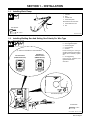
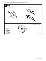
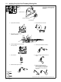
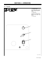
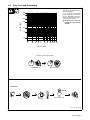
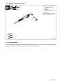
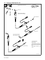
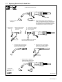
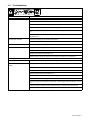
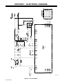
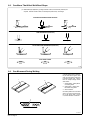
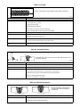
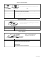
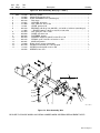
June 1996
Form: OM-1314
Effective With Serial No. KG171523
OWNER’S
MANUAL
Millermatic® 155 And M-15 Gun
230 Volt Wire Welder
Rated Welding
Output
Amperage
Range
Maximum
Open-Circuit
Voltage DC
Amperes Input at
Rated Load Output 115 V, 60 Hz,
Single-Phase
KVA
KW
Weight
Overall
Dimensions
Length: 17 in
(432 mm)
130 A @ 20.5 Volts
DC, 30% Duty Cycle
40 − 170
20.5
(0.27)*
33
4.7
(.05)*
4
(.04)*
80 lb
(36.3 kg)
Width: 10 in
(254 mm)
Height: 15-1/2 in
(394 mm)
Wire Type
And Dia
Solid/
Stainless
Flux Cored/
Aluminum
Calculated Wire
Speed Range At
No Load
Max Wire Feed Speed While Welding
.023 − .035 in
(0.6 − 0.9 mm)
.030 − .045 in
(0.8 − 1.1 mm)
126 − 722 IPM
(3.2 − 18.3 m/min)
500 IPM
(12.7 m/min)
* While idling
cover_om 4/95 − ST-800 091-C
© 1996 MILLER Electric Mfg. Co.
PRINTED IN USA
SECTION 1 − INSTALLATION
1-1. Installing Work Clamp
1
1
2
3
4
Insulator
Bolt
Smaller Hole
Work Clamp Tabs
Bend tabs around work cable.
6
2
5
Tools Needed:
5
6
Work Cable From Unit
Nut
3
4
3/8, 7/16 in
Ref. ST-025 190-D
1-2. Installing Welding Gun And Setting Gun Polarity For Wire Type
1
2
3
4
5
. Follow wire manufacturer’s recommendation.
Loosen securing nut. Insert gun
end through opening until it bottoms
against drive assembly. Tighten
nut.
Solid Steel Or
Aluminum Wires
(GMAW−With Gas)
Flux Cored Wires
(FCAW−Without Gas)
Gun Opening
Gun Trigger Receptacle
Gun Securing Nut
Drive Assembly
Gun End
6
Gun Trigger Plug
Insert plug into receptacle, and
tighten threaded collar.
Close door.
Straight Polarity
DCEN
Reverse Polarity
DCEP
1
2
Front Panel Openings
3
4
Tools Needed:
6
5
5/16 in
ST-149 328-B / Ref. ST-159 270
OM-1314 Page 5
1-3. Electrical Service Guide
Input Voltage
230
Input Amperes At Rated Output
20.5
Max Recommended Standard Fuse Or Circuit Breaker Rating In Amperes
25
Min Input Conductor Size In AWG/Kcmil
14
Max Recommended Input Conductor Length In Feet (Meters)
64 (19)
Min Grounding Conductor Size In AWG/Kcmil
14
Reference: 1996 National Electrical Code (NEC)
S-0092-J
1-4. Selecting A Location And Connecting Input Power
1
Rating Label
Supply correct input power.
2
3
Plug
Receptacle
Connect plug to receptacle.
4
18 in (457 mm) of
space for airflow
4
Line Disconnect Device
See Section 1-3.
Y Special installation may be
required where gasoline or
volatile liquids are present −
see NEC Article 511 or CEC
Section 20.
L1
L2
Y Always connect
grounding
conductor first.
= GND/PE
3
L1
L2
1
2
230 VAC, 1
Y Do not move or operate unit
where it could tip.
ssb2.2* 1/94 − ST-801 504
OM-1314 Page 6
1-5. Installing Wire Spool And Adjusting Hub Tension
Standard Wire Spool
1 Lb Wire Spool
When a slight force is needed
to turn spool, tension is set.
Tools Needed:
15/16 in
S-0499
OM-1314 Page 7
1-6. Installing Drive Roll And Threading Welding Wire
Install drive roll onto shaft with desired groove in, and one set screw
facing flat side of shaft. Tighten both
set screws.
1
Install drive roll.
For Flux Cored Wire
For Solid Wire
2
Open pressure assembly.
3
Pull and hold wire; cut off end.
6 in
(150 mm)
4
Push wire thru guides into gun;
continue to hold wire.
5
Close and tighten pressure assembly,
and let go of wire.
6
Remove gun nozzle and contact tip.
7
Turn power On.
8
Press gun trigger until wire comes out
of gun.
9
Reinstall contact tip and nozzle.
10 Feed wire to check drive roll
pressure. Tighten knob enough to
prevent slipping. Cut off wire; leave
1/4−1/2 in (6−13 mm). Close and
latch door.
Tools Needed:
WOOD
Ref. ST-149 266-B / Ref. ST-149 326-B / Ref. 150 093-A / Ref. 180 968 / S-0627-A
OM-1314 Page 8
SECTION 2 − OPERATION
2-1. Controls
1
Wire Speed Control
Use control to select a wire feed
speed. As Voltage switch setting increases, wire speed range also increases.
2
Voltage Switch
The higher the selected number,
the thicker the material that can be
welded. Do not switch while
welding.
3
Power Switch
1
2
3
Ref. ST-180 968
OM-1314 Page 9
NOTES
OM-1314 Page 10
2-2. Duty Cycle And Overheating
Duty Cycle is percentage of 10 minutes that unit can weld at rated load
without overheating.
300
If unit overheats, thermostat(s)
opens, output stops, and cooling
fan runs. Wait fifteen minutes for
unit to cool. Reduce amperage or
duty cycle before welding.
250
DC AMPERES
200
Y Exceeding duty cycle can
damage unit or gun and void
warranty.
150
100
75
50
10
15
20
25 30
40
50 60 70 80 100
% DUTY CYCLE
30% Duty Cycle At 130 Amperes
3 Minutes Welding
7 Minutes Resting
Overheating
A or V
0
15
Minutes
OR
Reduce Duty Cycle
duty1 4/95 − SB-180 844
OM-1314 Page 11
SECTION 3 − MAINTENANCE & TROUBLESHOOTING
3-1. Maintenance
. Maintain more often
Y Disconnect power
before maintaining.
during severe conditions.
3 Months
Repair Or
Replace
Cracked
Cables
And Cords
Replace
Damaged Or
Unreadable
Labels
Clean And
Tighten
Weld
Connections
6 Months
Blow Out Or
Vacuum Inside
stat_maint − 2/96
3-2. Fuse F1
1
2
Y Turn Off unit, disconnect input power. Unlatch door and
remove wrapper.
1
2
Circuit Board PC1
Fuse F1 (See Parts List For
Rating)
If F1 opens, wire drive motor shuts
down. Replace F1 if open.
Reinstall wrapper, and latch door.
Tools Needed:
3/8 in
Ref. ST-801 552
3-3. Short Circuit Shutdown
If contact tip is shorted and sticks to workpiece, the unit shuts down, but fan runs. To resume operation, release gun
trigger, turn Off unit, and remove contact tip from workpiece. Check contact tip and replace if damaged. Turn On unit to
continue operation.
OM-1314 Page 12
3-4. Replacing Gun Contact Tip
Y Turn Off power before
replacing contact tip.
1
2
Nozzle
Contact Tip
Cut off welding wire at contact tip.
Remove nozzle.
Remove contact tip and install new
contact tip. Reinstall nozzle.
2
1
Tools Needed:
ST-149 326-B
3-5. Unicable Repair
To repair or replace unicable, order Unicable Clamp Kit, part number 172 017. Kit includes all required instructions,
clamps, inner support tube, compression clip, switch leads, and connectors.
OM-1314 Page 13
3-6. Cleaning Or Replacing Gun Liner
Tools Needed:
Y Disconnect gun from unit.
3/8 in
Head Tube
Remove nozzle, contact tip,
adapter, and wire outlet guide.
3/8 in
Wire Outlet Guide
Remove liner.
Lay gun cable out straight
before installing new liner.
To Reassemble Gun:
Insert new liner.
Install and tighten wire outlet guide.
Blow out gun casing.
Cut liner off 3/4 in (20 mm) (3/8 in
[9.5 mm] for aluminum) from head
tube.
Install adapter, contact tip, and
nozzle.
Ref. ST-800 797-A
OM-1314 Page 14
3-7. Replacing Switch And/Or Head Tube
Y Disconnect gun from unit.
3
1
4
2
Remove handle
locking nut.
Secure head
tube in vice.
5
Remove shock washers
from front and rear of
head tube.
6
Slide handle.
Remove switch housing. Note: If installing new
switch, push switch lead connectors onto terminal of
new switch (polarity is not important). Install switch
back into handle, and secure with handle locking nut.
If replacing head tube, continue to end of figure.
Loosen jam nut. Remove
from vice and turn head
tube out by hand.
Do not disturb cable connection between
cable connector and connector nut.
7
Install both existing shock washers
to new head tube and hand-tighten
head tube into connector cable.
9
8
Place head tube in vice and tighten
to within 1/8 in (3.2 mm) spacing between connector cable and body.
Remove from vice. Reposition
handle and install switch housing.
Secure with handle locking nut.
Tools Needed:
3/4 in
Ref. ST-800 795-A
OM-1314 Page 15
3-8. Cleaning Or Repairing Drive Assembly
Y Turn Off power before
cleaning or repairing drive
assembly.
1
2
Wire Spool
Nozzle
Cut welding wire off at nozzle.
Retract wire onto spool and secure.
3
4
5
6
7
Pressure Roll Arm
Cotter Pin
Pin
Screw
Bearing
Remove bearing. Install new bearing and secure with screw. Reinstall
arm onto pin and secure with cotter
pin.
8
9
Setscrew
Drive Roll
Remove drive roll.
1
Push drive roll onto shaft with
desired groove in. Turn drive roll so
one setscrew faces flat side of
shaft, and tighten both setscrews.
2
5
6
8
7
10 Wire Inlet Guide
Remove guide by pressing on
barbed area or cutting off one end
near housing and pulling it out of
hole. Push new guide into hole from
rear until it snaps in place.
Close door.
3
4
9
10
8
Tools Needed:
5/64 in
Ref. ST-150 093-A / ST-149 266-B
OM-1314 Page 16
3-9. Troubleshooting
Welding Trouble
No weld output; wire does not feed.
Remedy
Secure power cord plug in receptacle (see Section 1-4).
Check and replace power switch if necessary.
Check fuse F1, and replace if necessary (see Section 3-2).
Replace building line fuse or reset circuit breaker if open (see Section 1-4).
Secure gun trigger plug in receptacle or repair leads, or replace trigger switch (see Section 1-2 and/or
3-7).
Thermostat TP1 open (overheating). Allow fan to run; the thermostat will close when the unit has cooled
(see Section 2-2).
No weld output; wire feeds.
Connect work clamp to get good metal to metal contact.
Replace contact tip (see Section 3-4).
Low weld output.
Connect unit to proper input voltage or check for low line voltage (see Section 1-4).
Low, high, or erratic wire speed.
Readjust front panel settings (see Section 2-1).
Change to correct groove in drive roll (see Section 1-6).
Readjust drive roll pressure (see Section 1-6).
Replace inlet guide, contact tip, and/or liner if necessary (see Sections 3-8, 3-4 and/or 3-6).
Wire Drive/Gun Trouble
Remedy
Electrode wire feeding stops during Straighten gun cable and/or replace damaged parts (see Section 3-6).
welding.
Adjust drive roll pressure (see Section 1-6).
Readjust hub tension (see Section 1-5).
Replace contact tip if blocked (see Section 3-4).
Clean or replace wire inlet guide or liner if dirty or plugged (see Section 3-8, and Section 3-6).
Replace drive roll if worn or slipping (see Section 1-6).
Secure gun trigger plug in receptacle or repair leads, or replace trigger switch (see Section 1-2 and/or
3-7).
Check and clear any restrictions at drive assembly and liner (see Section 3-8, and Section 3-6).
Have nearest Factory Authorized Service Agent check drive motor.
OM-1314 Page 17
SECTION 4 − SAFETY PRECAUTIONS FOR ARC WELDING
OM-1314 − 6/96
safety_som1 4/95
4-1. Symbol Usage
Means Warning! Watch Out! There are possible hazards with this
procedure! The possible hazards are shown in the adjoining symbols.
Y Marks a special safety message.
. Means NOTE; not safety related.
This group of symbols means Warning! Watch Out! possible ELECTRIC SHOCK, MOVING PARTS,
and HOT PARTS hazards. Consult symbols and related instructions below for necessary actions to
avoid the hazards.
4-2. Arc Welding Hazards
WARNING
The symbols shown below are used throughout this manual to call attention to and identify possible
hazards. When you see the symbol, watch out, and follow the related instructions to avoid the hazard. The
safety information given below is only a summary of the more complete safety information found in the
Safety Standards listed in Section 4-4. Read and follow all Safety Standards.
Only qualified persons should install, operate, maintain, and repair this unit.
During operation, keep everybody, especially children, away.
ELECTRIC SHOCK can kill.
Touching live electrical parts can cause fatal shocks
or severe burns. The electrode and work circuit is
electrically live whenever the output is on. The input
power circuit and machine internal circuits are also
live when power is on. In semiautomatic or
automatic wire welding, the wire, wire reel, drive roll
housing, and all metal parts touching the welding
wire are electrically live. Incorrectly installed or
improperly grounded equipment is a hazard.
1. Do not touch live electrical parts.
2. Wear dry, hole-free insulating gloves and body protection.
3. Insulate yourself from work and ground using dry insulating mats
or covers big enough to prevent any physical contact with the
work or ground.
4. Disconnect input power or stop engine before installing or
servicing this equipment. Lockout/tagout input power according
to OSHA 29 CFR 1910.147 (see Safety Standards).
5. Properly install and ground this equipment according to its
Owner’s Manual and national, state, and local codes.
6. Always verify the supply ground − check and be sure that input
power cord ground wire is properly connected to ground terminal
ARC RAYS can burn eyes and skin;
NOISE can damage hearing; FLYING
SLAG OR SPARKS can injure eyes.
NOISE
Arc rays from the welding process produce intense
visible and invisible (ultraviolet and infrared) rays
that can burn eyes and skin. Noise from some
processes can damage hearing. Chipping, grinding,
and welds cooling throw off pieces of metal or slag.
7. When making input connections, attach proper grounding
conductor first − double-check connections.
8. Frequently inspect input power cord for damage or bare wiring −
replace cord immediately if damaged − bare wiring can kill.
9. Turn off all equipment when not in use.
10. Do not use worn, damaged, undersized, or poorly spliced cables.
11. Do not drape cables over your body.
12. If earth grounding of the workpiece is required, ground it directly
with a separate cable − do not use work clamp or work cable.
13. Do not touch electrode if you are in contact with the work, ground,
or another electrode from a different machine.
14. Use only well-maintained equipment. Repair or replace damaged
parts at once. Maintain unit according to manual.
15. Wear a safety harness if working above floor level.
16. Keep all panels and covers securely in place.
17. Clamp work cable with good metal-to-metal contact to workpiece
or worktable as near the weld as practical.
ARC RAYS
2. Wear a welding helmet fitted with a proper shade of filter to protect
your face and eyes when welding or watching (see ANSI Z49.1
and Z87.1 listed in Safety Standards).
3. Wear approved safety glasses with side shields.
4. Use protective screens or barriers to protect others from flash
and glare; warn others not to watch the arc.
5. Wear protective clothing made from durable, flame-resistant
material (wool and leather) and foot protection.
1. Use approved ear plugs or ear muffs if noise level is high.
FUMES AND GASES can
hazardous to your health.
in disconnect box or that cord plug is connected to a properly
grounded receptacle outlet.
be
Welding produces fumes and gases. Breathing
these fumes and gases can be hazardous to your
health.
1. Keep your head out of the fumes. Do not breathe the fumes.
2. If inside, ventilate the area and/or use exhaust at the arc to
remove welding fumes and gases.
3. If ventilation is poor, use an approved air-supplied respirator.
4. Read the Material Safety Data Sheets (MSDSs) and the
manufacturer’s instruction for metals, consumables, coatings,
cleaners, and degreasers.
5. Work in a confined space only if it is well ventilated, or while
wearing an air-supplied respirator. Always have a trained
watchperson nearby. Welding fumes and gases can displace air
and lower the oxygen level causing injury or death. Be sure the
breathing air is safe.
6. Do not weld in locations near degreasing, cleaning, or spraying
operations. The heat and rays of the arc can react with vapors to
form highly toxic and irritating gases.
7. Do not weld on coated metals, such as galvanized, lead, or
cadmium plated steel, unless the coating is removed from the
weld area, the area is well ventilated, and if necessary, while
wearing an air-supplied respirator. The coatings and any metals
containing these elements can give off toxic fumes if welded.
OM-1314 Page 1
CYLINDERS can explode if damaged.
Shielding gas cylinders contain gas under high
pressure. If damaged, a cylinder can explode. Since
gas cylinders are normally part of the welding
process, be sure to treat them carefully.
1. Protect compressed gas cylinders from excessive heat,
mechanical shocks, slag, open flames, sparks, and arcs.
2. Install cylinders in an upright position by securing to a stationary
support or cylinder rack to prevent falling or tipping.
3. Keep cylinders away from any welding or other electrical circuits.
WELDING
explosion.
can
cause
fire
or
Welding on closed containers, such as tanks,
drums, or pipes, can cause them to blow up. Sparks
can fly off from the welding arc. The flying sparks,
hot workpiece, and hot equipment can cause fires
and burns. Accidental contact of electrode to metal
objects can cause sparks, explosion, overheating,
or fire. Check and be sure the area is safe before
doing any welding.
1. Protect yourself and others from flying sparks and hot metal.
2. Do not weld where flying sparks can strike flammable material.
3. Remove all flammables within 35 ft (10.7 m) of the welding arc. If
this is not possible, tightly cover them with approved covers.
4. Be alert that welding sparks and hot materials from welding can
easily go through small cracks and openings to adjacent areas.
4.
5.
6.
7.
Never drape a welding torch over a gas cylinder.
Never allow a welding electrode to touch any cylinder.
Never weld on a pressurized cylinder − explosion will result.
Use only correct shielding gas cylinders, regulators, hoses, and
fittings designed for the specific application; maintain them and
associated parts in good condition.
8. Turn face away from valve outlet when opening cylinder valve.
9. Keep protective cap in place over valve except when cylinder is in
use or connected for use.
10. Read and follow instructions on compressed gas cylinders,
associated equipment, and CGA publication P-1 listed in Safety
Standards.
5. Watch for fire, and keep a fire extinguisher nearby.
6. Be aware that welding on a ceiling, floor, bulkhead, or partition
can cause fire on the hidden side.
7. Do not weld on closed containers such as tanks, drums, or pipes,
unless they are properly prepared according to AWS F4.1 (see
Safety Standards).
8. Connect work cable to the work as close to the welding area as
practical to prevent welding current from traveling long, possibly
unknown paths and causing electric shock and fire hazards.
9. Do not use welder to thaw frozen pipes.
10. Remove stick electrode from holder or cut off welding wire at
contact tip when not in use.
11. Wear oil-free protective garments such as leather gloves, heavy
shirt, cuffless trousers, high shoes, and a cap.
12. Remove any combustibles, such as a butane lighter or matches,
from your person before doing any welding.
4-3. Additional Installation, Operation, And Maintenance Hazards
FIRE OR EXPLOSION can result from
placing unit on, over, or near
combustible surfaces.
1. Do not locate unit on, over, or near combustible
surfaces.
2. Do not install unit near flammables.
FALLING EQUIPMENT can cause
serious personal injury and equipment
damage.
1. Use lifting eye to lift unit only, NOT running gear,
gas cylinders, or any other accessories.
2. Use equipment of adequate capacity to lift unit.
3. If using lift forks to move unit, be sure forks are long
enough to extend beyond opposite side of unit.
HOT PARTS can cause severe burns.
1. Do not touch hot parts bare handed.
2. Allow cooling period before working on gun or
torch.
MOVING PARTS can cause injury.
1. Keep away from moving parts such as fans.
2. Keep all doors, panels, covers, and guards closed
and securely in place.
MAGNETIC
CURRENTS
operation.
FIELDS FROM HIGH
can affect pacemaker
1. Pacemaker wearers keep away.
2. Wearers should consult their doctor before going
near arc welding, gouging, or spot welding
operations.
OM-1314 Page 2
MOVING PARTS can cause injury.
1. Keep away from moving parts.
2. Keep away from pinch points such as drive rolls.
FLYING PIECES OF METAL or DIRT can
injure eyes.
1. Wear safety glasses with side shields or face
shield.
WELDING WIRE can cause puncture
wounds.
1. Do not press gun trigger until instructed to do so.
2. Do not point gun toward any part of the body, other
people, or any metal when threading welding wire.
HIGH-FREQUENCY RADIATION can
interfere with radio navigation, safety
services,
computers,
and
communications equipment.
1. Have only qualified persons familiar with electronic
equipment perform this installation.
2. The user is responsible for having a qualified
electrician promptly correct any interference
problem resulting from the installation.
3. If notified by the FCC about interference, stop using
the equipment at once.
4. Have the installation regularly checked and
maintained.
5. Keep high-frequency source doors and panels
tightly shut, keep spark gaps at correct setting, and
use grounding and shielding to minimize the
possibility of interference.
OVERUSE can cause OVERHEATED
EQUIPMENT.
SIGNIFICANT DC VOLTAGE exists after
removal of input power on inverters.
1. Allow cooling period.
2. Reduce current or reduce duty cycle before
starting to weld again.
3. Follow rated duty cycle.
1. Turn Off inverter, disconnect input power, and
discharge input capacitors according to
instructions in Maintenance Section before
touching any parts.
STATIC ELECTRICITY can
parts on circuit boards.
damage
1. Put on grounded wrist strap BEFORE handling
boards or parts.
2. Use proper static-proof bags and boxes to store,
move, or ship PC boards.
BUILDUP OF SHIELDING GAS can harm
health or kill.
1. Shut off shielding gas supply when not in use.
4-4. Principal Safety Standards
Safety in Welding and Cutting, ANSI Standard Z49.1, from American
Welding Society, 550 N.W. LeJeune Rd, Miami FL 33126
Safety and Health Standards, OSHA 29 CFR 1910, from
Superintendent of Documents, U.S. Government Printing Office,
Washington, D.C. 20402.
Recommended Safe Practices for the Preparation for Welding and
Cutting of Containers That Have Held Hazardous Substances,
American Welding Society Standard AWS F4.1, from American
Welding Society, 550 N.W. LeJeune Rd, Miami, FL 33126
National Electrical Code, NFPA Standard 70, from National Fire
Protection Association, Batterymarch Park, Quincy, MA 02269.
Safe Handling of Compressed Gases in Cylinders, CGA Pamphlet
P-1, from Compressed Gas Association, 1235 Jefferson Davis
Highway, Suite 501, Arlington, VA 22202.
Code for Safety in Welding and Cutting, CSA Standard W117.2, from
Canadian Standards Association, Standards Sales, 178 Rexdale
Boulevard, Rexdale, Ontario, Canada M9W 1R3.
Safe Practices For Occupation And Educational Eye And Face
Protection, ANSI Standard Z87.1, from American National Standards
Institute, 1430 Broadway, New York, NY 10018.
Cutting And Welding Processes, NFPA Standard 51B, from National
Fire Protection Association, Batterymarch Park, Quincy, MA 02269.
4-5. EMF Information
Considerations About Welding And The Effects Of Low Frequency
Electric And Magnetic Fields
The following is a quotation from the General Conclusions Section of
the U.S. Congress, Office of Technology Assessment, Biological
Effects of Power Frequency Electric & Magnetic Fields − Background
Paper, OTA-BP-E-53 (Washington, DC: U.S. Government Printing
Office, May 1989): “. . . there is now a very large volume of scientific
findings based on experiments at the cellular level and from studies
with animals and people which clearly establish that low frequency
magnetic fields can interact with, and produce changes in, biological
systems. While most of this work is of very high quality, the results are
complex. Current scientific understanding does not yet allow us to
interpret the evidence in a single coherent framework. Even more
frustrating, it does not yet allow us to draw definite conclusions about
questions of possible risk or to offer clear science-based advice on
strategies to minimize or avoid potential risks.”
To reduce magnetic fields in the workplace, use the following
procedures:
1. Keep cables close together by twisting or taping them.
2. Arrange cables to one side and away from the operator.
3. Do not coil or drape cables around the body.
4. Keep welding power source and cables as far away as
practical.
5. Connect work clamp to workpiece as close to the weld as
possible.
About Pacemakers:
The above procedures are also recommended for pacemaker
wearers. Consult your doctor for complete information.
OM-1314 Page 3
SECTION 5 − ELECTRICAL DIAGRAM
SB-180 784-A
Figure 5-1. Circuit Diagram
OM-1314 Page 4
SECTION 6 − WELDING METHODS & TROUBLESHOOTING
mod4.1* 9/92
A. Welding Methods
6-1. Holding And Positioning Welding Gun
. Cradle gun and rest hand on workpiece. Place tip of wire on seam before lowering helmet and pressing trigger. Welding wire is not energized until gun trigger is pressed.
Wire Extension (Stickout)
1/4 − 1/2 in (6 − 13 mm)
GROOVE WELDS
90°
0°-15°
90°
End View Of Work Angle
Side View Of Gun Angle
FILLET WELDS
45°
0°-15°
45°
End View Of Work Angle
Side View Of Gun Angle
S-0421-A
OM-1314 Page 5
6-2. Conditions That Affect Weld Bead Shape
. Weld bead shape depends on gun angle, direction of travel, wire extension (stickout), travel speed, thickness of base metal, wire feed speed (weld current), and voltage.
GUN ANGLES AND WELD BEAD PROFILES
10°
10°
Push
Perpendicular
Drag
WIRE EXTENSIONS (STICKOUT)
Short
Normal
Long
FILLET WELD WIRE EXTENSIONS (STICKOUT)
Short
Normal
Long
GUN TRAVEL SPEED
Slow
Normal
Fast
S-0634
6-3. Gun Movement During Welding
1
2
A single stringer bead is satisfactory for most narrow groove weld
joints. For wide groove weld joints
or bridging across gaps, a weave
bead or multiple stringer beads
works better.
1
Stringer Bead − Steady Movement Along Seam
2
Weave Bead − Side To Side
Movement Along Seam
3
Weave Patterns
Use weave patterns to cover a wide
area in one pass of the electrode.
Do not let weave width exceed
2-1/2 times diameter of electrode.
3
S-0054-A
OM-1314 Page 6
6-4. Weld Bead Characteristics
Poor Weld Bead
1
2
4
3
1
Large Spatter Deposits
2
Rough, Uneven Bead
3
Slight Crater During Welding
4
Bad Overlap
5
Poor Penetration
5
S-0053-A
Good Weld Bead
1
5
2
3
4
1
Fine Spatter
2
Uniform Bead
3
Moderate Crater During
Welding
Weld a new bead or layer for each
1/8 in (3.2 mm) thickness in metals
being welded.
4
No Overlap
5
Good Penetration Into Base
Metal
Ref. S-0052-B
B.
Welding Troubleshooting
Table 6-1. Excessive Spatter
Excessive Spatter − scattering of molten metal particles that cool to
solid form near weld bead.
S-0636
Possible Causes
Corrective Actions
Wire feed speed too high.
Select lower wire feed speed.
Voltage too high.
Select lower voltage range.
Wire extension (stickout) too long.
Use shorter wire extension (stickout).
Workpiece dirty.
Remove oil, moisture, rust, and paint, etc. from work surface before welding.
Insufficient shielding gas at welding arc. Increase flow of shielding gas at regulator/flowmeter and/or prevent drafts near welding arc.
Dirty welding wire.
Use clean, dry welding wire.
Eliminate oil or lubricant on welding wire.
OM-1314 Page 7
Table 6-2. Porosity
Porosity − small cavities or holes resulting from gas pockets in weld metal.
S-0635
Possible Causes
Inadequate shielding gas coverage.
Corrective Actions
Check for proper gas flow rate.
Remove spatter from gun nozzle.
Check gas hoses for leaks.
Eliminate drafts near welding arc.
Place nozzle 1/4 to 1/2 in (6-13 mm) from workpiece.
Hold gun near bead at end of weld until molten metal solidifies.
Wrong gas.
Use welding grade shielding gas; change to different gas.
Dirty welding wire.
Use clean, dry welding wire.
Eliminate oil or lubricant on welding wire.
Workpiece dirty.
Remove oil, moisture, rust, and paint, etc. from work surface before welding.
Use a more highly deoxidizing welding wire (contact supplier).
Welding wire extends too far out of
nozzle.
Be sure welding wire does not extend more than 1/2 in (13 mm) beyond nozzle.
Table 6-3. Incomplete Fusion
Incomplete Fusion − failure of weld metal to fuse completely with base metal or
a preceeding weld bead.
S-0637
Possible Causes
Corrective Actions
Workpiece dirty.
Remove oil, moisture, rust, and paint, etc. from work surface before welding.
Insufficient heat input.
Select higher voltage range and/or adjust wire feed speed.
Improper welding technique.
Place stringer bead in proper location(s) at joint during welding.
Adjust the work angle or widen groove to access bottom during welding.
Momentarily hold arc on groove side walls when using weaving technique.
Keep arc on leading edge of weld puddle.
Use correct gun angle of 0 to 15 degrees.
Table 6-4. Excessive Penetration
Excessive Penetration − weld metal melting through base metal and hanging underneath weld.
Excessive Penetration
Possible Causes
Excessive heat input.
Good Penetration
Corrective Actions
Select lower voltage range and reduce wire feed speed.
Increase and/or maintain steady travel speed.
OM-1314 Page 8
Table 6-5. Lack Of Penetration
Lack Of Penetration − shallow fusion between weld metal and base metal.
Lack of Penetration
Good Penetration
S-0638
Possible Causes
Corrective Actions
Improper joint preparation.
Material too thick. Joint preparation and design must provide access to bottom of groove while maintaining proper welding wire extension and arc characteristics.
Improper weld technique.
Maintain normal gun angle of 0 to 15 degrees to achieve maximum penetration.
Keep arc on leading edge of weld puddle.
Be sure welding wire does not extend more than 1/2 in (13 mm) beyond nozzle.
Insufficient heat input.
Select higher wire feed speed and/or select higher voltage range.
Reduce travel speed.
Table 6-6. Burn-Through
Burn-Through − weld metal melting completely through base metal resulting in
holes where no metal remains.
Possible Causes
Excessive heat input.
Corrective Actions
Select lower voltage range and reduce wire feed speed.
Increase and/or maintain steady travel speed.
Table 6-7. Distortion
Distortion − contraction of weld metal during
welding that forces base metal to move.
Base metal moves
in the direction of
the weld bead.
Possible Causes
Excessive heat input.
Corrective Actions
Use restraint (clamp) to hold base metal in position.
Make tack welds along joint before starting welding operation.
Select lower voltage range and reduce wire feed speed.
Increase travel speed.
Weld in small segments and allow cooling between welds.
OM-1314 Page 9
Table 6-8. Waviness Of Bead
Waviness Of Bead − weld metal that is not parallel and does not cover joint formed
by base metal.
Possible Causes
Corrective Actions
Welding wire extends too far out of
nozzle.
Be sure welding wire does not extend more than 1/2 in (13 mm) beyond nozzle.
Unsteady hand.
Support hand on solid surface or use two hands. Practice technique.
OM-1314 Page 10
Fig 7-2
43
1
Fig 7-3
42
46
41
45
47
48
49
50
44
2 3
4
5
6
40
39
7
12
11
38
10
13
8
15
14
37
16
9
36
17
23
24
19
35
20
18
22
34
33
21
32
25
31
26
30
27 28
29
SECTION 7 − PARTS LIST
ST-801 633
Figure 7-1. Main Assembly
OM-1314 Page 11
Item
No.
Dia.
Mkgs.
Part
No.
Description
Quantity
Figure 7-1. Main Assembly
. . . 1 . . . . . . . . . . 131 315 . . DRIVE ASSEMBLY, wire (Fig 7-3) . . . . . . . . . . . . . . . . . . . . . . . . . . . . . . . . . . . . . 1
. . . 2 . . . . . . . . . . 010 909 . . NUT, 375-16 . . . . . . . . . . . . . . . . . . . . . . . . . . . . . . . . . . . . . . . . . . . . . . . . . . . . . . . 1
. . . 3 . . . . . . . . . . 010 910 . . WASHER, flat .406 ID x 0.81 OD . . . . . . . . . . . . . . . . . . . . . . . . . . . . . . . . . . . . . . 2
. . . 4 . . . . . . . . . . 073 355 . . SPRING, cprsn .625 OD x 0.93 W . . . . . . . . . . . . . . . . . . . . . . . . . . . . . . . . . . . . 1
. . . 5 . . . . . . . . . . 111 998 . . PIN, cotter hair .120dia x 2.3 . . . . . . . . . . . . . . . . . . . . . . . . . . . . . . . . . . . . . . . . . 1
. . . 6 . . . . . . . . . . 111 929 . . HUB, spool . . . . . . . . . . . . . . . . . . . . . . . . . . . . . . . . . . . . . . . . . . . . . . . . . . . . . . . . . 1
. . . 7 . . . . . . . . . . 147 562 . . BAFFLE, center . . . . . . . . . . . . . . . . . . . . . . . . . . . . . . . . . . . . . . . . . . . . . . . . . . . . 1
. . . 8 . . . FM . . 117 014 . . MOTOR, fan 230V 50/60 Hz 2600RPM . . . . . . . . . . . . . . . . . . . . . . . . . . . . . . . . 1
. . . 9 . . . . . . . . . . 005 656 . . BLADE, fan 6.000 4wg 30 deg . . . . . . . . . . . . . . . . . . . . . . . . . . . . . . . . . . . . . . . . 1
. . . 10 . . . CR2 . . 108 358 . . CONTACTOR, def prp 25A 2P 24V . . . . . . . . . . . . . . . . . . . . . . . . . . . . . . . . . . . . 1
. . . 11 . . . SR2 . . 180 791 . . RECTIFIER, si 1PH 140A 200PIV . . . . . . . . . . . . . . . . . . . . . . . . . . . . . . . . . . . . . 1
. . . 12 . . . . . . . . . . 147 461 . . PANEL, front . . . . . . . . . . . . . . . . . . . . . . . . . . . . . . . . . . . . . . . . . . . . . . . . . . . . . . . 1
. . . 13 . . . . R1 . . 000 101 . . RHEOSTAT, WW 25W 25 ohm . . . . . . . . . . . . . . . . . . . . . . . . . . . . . . . . . . . . . . . 1
. . . 14 . . . . S2 . . 180 777 . . SWITCH, rotary 6 pin 1P 600V . . . . . . . . . . . . . . . . . . . . . . . . . . . . . . . . . . . . . . . 1
. . . 15 . . . RC3 . . 048 282 . . RECEPTACLE w/SOCKETS . . . . . . . . . . . . . . . . . . . . . . . . . . . . . . . . . . . . . . . . . 1
. . . 16 . . . . . . . . . . 147 560 . . PANEL, side lower . . . . . . . . . . . . . . . . . . . . . . . . . . . . . . . . . . . . . . . . . . . . . . . . . . 1
. . . 17 . . . . T1 . . 180 786 . . TRANSFORMER, power main . . . . . . . . . . . . . . . . . . . . . . . . . . . . . . . . . . . . . . . . 1
. . . 18 . . . PC1 . . 172 543 . . CIRCUIT CARD, (consisting of) . . . . . . . . . . . . . . . . . . . . . . . . . . . . . . . . . . . . . . . 1
. . . 19 . . . . F1 . . 073 426 . . . . FUSE, mintr slo-blo 5A 250V . . . . . . . . . . . . . . . . . . . . . . . . . . . . . . . . . . . . . . . 1
. . . 20 . . . CR2 . . 080 388 . . . . RELAY, encl 24VAC 3PDT 10A/120VAC . . . . . . . . . . . . . . . . . . . . . . . . . . . . . . 1
. . . . . . . . . . . . . . . . 173 299 . . CLIP, hold-down relay . . . . . . . . . . . . . . . . . . . . . . . . . . . . . . . . . . . . . . . . . . . . . . . 1
. . . 21 . . . . . . . . . . 110 375 . . STAND-OFF, support PC card . . . . . . . . . . . . . . . . . . . . . . . . . . . . . . . . . . . . . . . . 4
. . . 22 . . . . . . . . . . 147 563 . . WRAPPER . . . . . . . . . . . . . . . . . . . . . . . . . . . . . . . . . . . . . . . . . . . . . . . . . . . . . . . . 1
. . . 23 . . . . . . . . . . 089 899 . . LATCH, slide flush . . . . . . . . . . . . . . . . . . . . . . . . . . . . . . . . . . . . . . . . . . . . . . . . . . 1
. . . 24 . . . . . . . . . . 134 327 . . LABEL, warning general precautionary . . . . . . . . . . . . . . . . . . . . . . . . . . . . . . . . . 1
. . . 25 . . . . . . . . . . 126 415 . . CLAMP, saddle . . . . . . . . . . . . . . . . . . . . . . . . . . . . . . . . . . . . . . . . . . . . . . . . . . . . . 1
. . . 26 . . . . . . . . . . 126 416 . . HANDLE, molded plastic . . . . . . . . . . . . . . . . . . . . . . . . . . . . . . . . . . . . . . . . . . . . . 1
. . . 27 . . . . . . . . . . 111 443 . . BUSHING, strain relief . . . . . . . . . . . . . . . . . . . . . . . . . . . . . . . . . . . . . . . . . . . . . . . 1
. . . 28 . . PLG1 . 152 118 . . CORD SET, 250V 6-50P 126A 3/c . . . . . . . . . . . . . . . . . . . . . . . . . . . . . . . . . . . . 1
. . . 29 . . . . . . . . . . 605 227 . . NUT, 750-14 knurled . . . . . . . . . . . . . . . . . . . . . . . . . . . . . . . . . . . . . . . . . . . . . . . . 1
. . . 30 . . . . . . . . . . 180 849 . . PANEL, rear . . . . . . . . . . . . . . . . . . . . . . . . . . . . . . . . . . . . . . . . . . . . . . . . . . . . . . . . 1
. . . 31 . . . GS1 . . 128 751 . . VALVE, 230VAC 2 way . . . . . . . . . . . . . . . . . . . . . . . . . . . . . . . . . . . . . . . . . . . . . . 1
. . . 32 . . RC2,3 . 181 649 . . RESISTOR, WW fxd 40W 25 ohm . . . . . . . . . . . . . . . . . . . . . . . . . . . . . . . . . . . . 2
. . . 33 . . . VR1 . . 090 288 . . VARISTOR w/TERMINALS . . . . . . . . . . . . . . . . . . . . . . . . . . . . . . . . . . . . . . . . . . . 1
. . . 34 . . . . C1 . . 162 245 . . CAPACITOR, elctlt 140000uf . . . . . . . . . . . . . . . . . . . . . . . . . . . . . . . . . . . . . . . . . 1
. . . 35 . . . . . . . . . . 022 160 . . CLAMP, capacitor 3.000dia . . . . . . . . . . . . . . . . . . . . . . . . . . . . . . . . . . . . . . . . . . . 1
. . . 36 . . . . Z1 . . 180 793 . . STABILIZER . . . . . . . . . . . . . . . . . . . . . . . . . . . . . . . . . . . . . . . . . . . . . . . . . . . . . . . 1
. . . 37 . . . . . . . . . . 180 850 . . BASE . . . . . . . . . . . . . . . . . . . . . . . . . . . . . . . . . . . . . . . . . . . . . . . . . . . . . . . . . . . . . 1
. . . 38 . . . . . . . . . . 147 548 . . NUT, speed push-on type . . . . . . . . . . . . . . . . . . . . . . . . . . . . . . . . . . . . . . . . . . . . 12
. . . 39 . . . . . . . . . . 146 753 . . BEZEL, front/rear . . . . . . . . . . . . . . . . . . . . . . . . . . . . . . . . . . . . . . . . . . . . . . . . . . . 2
. . . 40 . . . . . . . . . . 010 368 . . CLAMP, work 200A . . . . . . . . . . . . . . . . . . . . . . . . . . . . . . . . . . . . . . . . . . . . . . . . . 1
. . . 41 . . . . . . . . . . 026 843 . . INSULATOR, vinyl blk . . . . . . . . . . . . . . . . . . . . . . . . . . . . . . . . . . . . . . . . . . . . . . . 2
. . . 42 . . . . . . . . . . 600 325 . . CABLE, weld cop strd No. 6 . . . . . . . . . . . . . . . . . . . . . . . . . . . . . . . . . . . . . . . . . 16ft
. . . 43 . . . . . . . . . . 169 903 . . M-15 GUN, (Fig 7-2) . . . . . . . . . . . . . . . . . . . . . . . . . . . . . . . . . . . . . . . . . . . . . . . . 1
. . . 44 . . . . . . . . . . 111 644 . . BUSHING, strain relief . . . . . . . . . . . . . . . . . . . . . . . . . . . . . . . . . . . . . . . . . . . . . . . 1
. . . 45 . . . . S1 . . 116 830 . . SWITCH, rocker DPST 10A 250VAC . . . . . . . . . . . . . . . . . . . . . . . . . . . . . . . . . . 1
. . . 46 . . . . . . . . . . . . . . . . . . . . . NAMEPLATE, (order by model and serial number) . . . . . . . . . . . . . . . . . . . . . . 1
. . . 47 . . . . . . . . . . . . . . . . . . . . . KNOB, pointer (included w/Item 14) . . . . . . . . . . . . . . . . . . . . . . . . . . . . . . . . . . . 1
. . . 48 . . . . . . . . . . 097 922 . . KNOB, pointer .875dia x .250 . . . . . . . . . . . . . . . . . . . . . . . . . . . . . . . . . . . . . . . . . 1
. . . 49 . . . TE1 . . 122 385 . . TERMINAL ASSEMBLY, (consisting of) . . . . . . . . . . . . . . . . . . . . . . . . . . . . . . . . 1
. . . 50 . . . . . . . . . . 174 504 . . . . LINK, jumper . . . . . . . . . . . . . . . . . . . . . . . . . . . . . . . . . . . . . . . . . . . . . . . . . . . . . 2
. . . . . . . . . . . . . . . . 113 149 . . CONNECTOR, rect 156 14skt . . . . . . . . . . . . . . . . . . . . . . . . . . . . . . . . . . . . . . . . 1
. . . . . . . . . . . . . . . . 110 160 . . CONNECTOR, rect 156 6skt . . . . . . . . . . . . . . . . . . . . . . . . . . . . . . . . . . . . . . . . . 1
. . . . . . . . . . . . . . . . 000 067 . . TIP, contact scr .030 wire x 1.125 . . . . . . . . . . . . . . . . . . . . . . . . . . . . . . . . . . . . . 2
. . . . . . . . . . . . . . . . 000 068 . . TIP, contact scr .035 wire x 1.125 . . . . . . . . . . . . . . . . . . . . . . . . . . . . . . . . . . . . . 3
. . . . . . . . . . . . . . . . 087 299 . . TIP, contact scr .023 wire x 1.125 . . . . . . . . . . . . . . . . . . . . . . . . . . . . . . . . . . . . . 3
. . . . . . . . . . . . . . . . 166 575 . . WRENCH, hex .078 across . . . . . . . . . . . . . . . . . . . . . . . . . . . . . . . . . . . . . . . . . . 1
. . . . . . . . . . . . . . . . 135 615 . . BUSHING, nylon .390 ID x .750 OD x .750 lg . . . . . . . . . . . . . . . . . . . . . . . . . . . 2
BE SURE TO PROVIDE MODEL AND SERIAL NUMBER WHEN ORDERING REPLACEMENT PARTS.
OM-1314 Page 12
1
2
3
4
5
6
7
6
8
9
10
11
13
14
15
25
27
26
12*
20
23
22
24
16
21
28
18
17
17
19
9
8
10
11
16
18
*Includes Item 17
19
ST-801 140
Figure 7-2. M-15 Gun
OM-1314 Page 13
Item
No.
Part
No.
169 903
...
...
...
...
...
...
...
...
...
...
...
...
...
...
...
...
...
...
...
...
...
...
...
...
...
...
...
...
...
...
...
...
...
1
2
2
2
3
4
5
6
7
8
9
9
10
10
11
12
13
14
15
16
17
18
19
20
21
22
23
24
25
25
26
27
28
. . . . . 169 715
. . . ♦087 299
. . . . . 000 067
. . . ♦000 068
. . . . . 169 716
. . . . . 170 470
. . . . . 170 471
. . . . . 169 717
. . . . . 169 718
. . . . . 169 738
. . . . . 169 719
. . . . . 169 732
. . . . . 169 720
. . . . . 169 733
. . . . . 169 721
. . . . . 172 017
. . . . . 169 735
. . . . . 169 742
. . . . . 169 743
. . . . . 169 740
. . . . . 169 746
. . . . . 169 737
. . . . . 169 741
. . . . . 180 433
. . . . . 180 551
. . . . . 180 427
. . . . . 173 521
. . . . . 079 974
. . . ♦172 257
. . . . . 172 258
. . . . . 079 975
. . . . . 169 723
. . . . . 169 739
Description
Figure 7-2. M-15 Gun (Fig 7-1 Item 43)
. . NOZZLE, slip type .500 orf flush . . . . . . . . . . . . . . . . . . . . . . . . . . . . . . . . . . . . . . . . . . . 1
. . TIP, contact scr .023 wire x 1.125 . . . . . . . . . . . . . . . . . . . . . . . . . . . . . . . . . . . . . . . . . . 2
. . TIP, contact scr .030 wire x 1.125 . . . . . . . . . . . . . . . . . . . . . . . . . . . . . . . . . . . . . . . . . . 2
. . TIP, contact scr .035 wire x 1.125 . . . . . . . . . . . . . . . . . . . . . . . . . . . . . . . . . . . . . . . . . . 2
. . ADAPTER, contact tip . . . . . . . . . . . . . . . . . . . . . . . . . . . . . . . . . . . . . . . . . . . . . . . . . . . . 1
. . RING, retaining . . . . . . . . . . . . . . . . . . . . . . . . . . . . . . . . . . . . . . . . . . . . . . . . . . . . . . . . . . 1
. . O-RING . . . . . . . . . . . . . . . . . . . . . . . . . . . . . . . . . . . . . . . . . . . . . . . . . . . . . . . . . . . . . . . . 1
. . WASHER, shock . . . . . . . . . . . . . . . . . . . . . . . . . . . . . . . . . . . . . . . . . . . . . . . . . . . . . . . . . 2
. . TUBE, head . . . . . . . . . . . . . . . . . . . . . . . . . . . . . . . . . . . . . . . . . . . . . . . . . . . . . . . . . . . . . 1
. . NUT, locking handle . . . . . . . . . . . . . . . . . . . . . . . . . . . . . . . . . . . . . . . . . . . . . . . . . . . . . . 2
. . NUT, jam (gun end) . . . . . . . . . . . . . . . . . . . . . . . . . . . . . . . . . . . . . . . . . . . . . . . . . . . . . . 1
. . NUT, jam . . . . . . . . . . . . . . . . . . . . . . . . . . . . . . . . . . . . . . . . . . . . . . . . . . . . . . . . . . . . . . . 1
. . CONNECTOR, cable (gun end) . . . . . . . . . . . . . . . . . . . . . . . . . . . . . . . . . . . . . . . . . . . . 1
. . CONNECTOR, cable . . . . . . . . . . . . . . . . . . . . . . . . . . . . . . . . . . . . . . . . . . . . . . . . . . . . . 1
. . NUT, connector . . . . . . . . . . . . . . . . . . . . . . . . . . . . . . . . . . . . . . . . . . . . . . . . . . . . . . . . . . 2
. . M15 UNICABLE CLAMP KIT, (consisting of) . . . . . . . . . . . . . . . . . . . . . . . . . . . . . . . . . 1
. . . . CLIP, compression . . . . . . . . . . . . . . . . . . . . . . . . . . . . . . . . . . . . . . . . . . . . . . . . . . . . . 2
. . . . TUBE, support . . . . . . . . . . . . . . . . . . . . . . . . . . . . . . . . . . . . . . . . . . . . . . . . . . . . . . . . . 2
. . . . CLAMP, inner . . . . . . . . . . . . . . . . . . . . . . . . . . . . . . . . . . . . . . . . . . . . . . . . . . . . . . . . . . 2
. . . . CLAMP, jacket . . . . . . . . . . . . . . . . . . . . . . . . . . . . . . . . . . . . . . . . . . . . . . . . . . . . . . . . . 2
. . . . CONNECTOR, switch lead . . . . . . . . . . . . . . . . . . . . . . . . . . . . . . . . . . . . . . . . . . . . . . 2
. . HANDLE . . . . . . . . . . . . . . . . . . . . . . . . . . . . . . . . . . . . . . . . . . . . . . . . . . . . . . . . . . . . . . . . 2
. . STRAIN RELIEF, cable . . . . . . . . . . . . . . . . . . . . . . . . . . . . . . . . . . . . . . . . . . . . . . . . . . . 2
. . CORD, trigger assembly (consisting of) . . . . . . . . . . . . . . . . . . . . . . . . . . . . . . . . . . . . . 1
. . . . BLOCK, terminal rear inc/dec . . . . . . . . . . . . . . . . . . . . . . . . . . . . . . . . . . . . . . . . . . . . 1
. . . . CORD, trigger . . . . . . . . . . . . . . . . . . . . . . . . . . . . . . . . . . . . . . . . . . . . . . . . . . . . . . . . . 1
. . CONNECTOR, feeder (consisting of) . . . . . . . . . . . . . . . . . . . . . . . . . . . . . . . . . . . . . . . 1
. . . . O-RING, .500 ID x .103CS rbr . . . . . . . . . . . . . . . . . . . . . . . . . . . . . . . . . . . . . . . . . . . 2
. . KIT, liner monocoil .023/.025 wire x 15ft (consisting of) . . . . . . . . . . . . . . . . . . . . . . . . 1
. . KIT, liner monocoil .030/.035 wire x 15ft (consisting of) . . . . . . . . . . . . . . . . . . . . . . . . 1
. . . . O-RING, .187 ID x .103CS rbr . . . . . . . . . . . . . . . . . . . . . . . . . . . . . . . . . . . . . . . . . . . 1
. . GUIDE, outlet . . . . . . . . . . . . . . . . . . . . . . . . . . . . . . . . . . . . . . . . . . . . . . . . . . . . . . . . . . . 1
. . SWITCH, trigger . . . . . . . . . . . . . . . . . . . . . . . . . . . . . . . . . . . . . . . . . . . . . . . . . . . . . . . . . 1
♦OPTIONAL
BE SURE TO PROVIDE MODEL AND STYLE NUMBER WHEN ORDERING REPLACEMENT PARTS.
OM-1314 Page 14
Quantity
Item Dia.
No. Mkgs.
Part
No.
Description
Quantity
Figure 7-3. Drive Assembly, Wire (Fig 7-1 Item 1)
. . . 1 . MOT .
... 2 ........
... 3 ........
... 4 ........
... 5 ........
... 6 ........
... 7 ........
... 8 ........
..............
... 9 ........
. . . 10 . . . . . . . .
. . . 11 . . . . . . . .
. . . 12 . . . . . . . .
. . . 13 . . . . . . . .
. . . 14 . . . . . . . .
. . . 15 . . . . . . . .
. . . 16 . . . . . . . .
. . . 17 . . . . . . . .
..............
173 446 . . . MOTOR, 12VDC . . . . . . . . . . . . . . . . . . . . . . . . . . . . . . . . . . . . . . . . . . . . . . . . . . . . . .
129 893 . . . INSULATOR, housing drive . . . . . . . . . . . . . . . . . . . . . . . . . . . . . . . . . . . . . . . . . . . . .
126 838 . . . DRIVE ASSEMBLY, wire (consisting of) . . . . . . . . . . . . . . . . . . . . . . . . . . . . . . . . . .
090 416 . . . . PIN, hinge . . . . . . . . . . . . . . . . . . . . . . . . . . . . . . . . . . . . . . . . . . . . . . . . . . . . . . . . . .
124 817 . . . . HOUSING, wire drive . . . . . . . . . . . . . . . . . . . . . . . . . . . . . . . . . . . . . . . . . . . . . . . .
151 828 . . . . PIN, cotter hair .054 x .750 . . . . . . . . . . . . . . . . . . . . . . . . . . . . . . . . . . . . . . . . . . .
112 031 . . . . LEVER, pressure roll . . . . . . . . . . . . . . . . . . . . . . . . . . . . . . . . . . . . . . . . . . . . . . . . .
090 443 . . . . BEARING, ball rdl sgl row .866 OD x .447 width x .315 bore (consisting of) . .
111 622 . . . . . . SPACER, bearing .196 ID x .310 OD x .500 collar . . . . . . . . . . . . . . . . . . . . . .
010 224 . . . . PIN, spring CS .187 x 1.000 . . . . . . . . . . . . . . . . . . . . . . . . . . . . . . . . . . . . . . . . . .
058 549 . . . . GUIDE, wire inlet 1/16 . . . . . . . . . . . . . . . . . . . . . . . . . . . . . . . . . . . . . . . . . . . . . . .
085 242 . . . . FASTENER, pinned . . . . . . . . . . . . . . . . . . . . . . . . . . . . . . . . . . . . . . . . . . . . . . . . . .
085 244 . . . . WASHER, cupped stl .328 ID x .812 OD x .125 . . . . . . . . . . . . . . . . . . . . . . . . . .
090 415 . . . . SPRING, cprsn .720 OD x .070 wire x 1.250 . . . . . . . . . . . . . . . . . . . . . . . . . . . .
092 237 . . . . KNOB, adj tension . . . . . . . . . . . . . . . . . . . . . . . . . . . . . . . . . . . . . . . . . . . . . . . . . . .
119 028 . . . ROLL, drive V groove combination . . . . . . . . . . . . . . . . . . . . . . . . . . . . . . . . . . . . . .
602 169 . . . SCREW, set stl sch 8-32 x .187 cup point . . . . . . . . . . . . . . . . . . . . . . . . . . . . . . . .
114 415 . . . SCREW, mach stl phflh 10-24 x .625 . . . . . . . . . . . . . . . . . . . . . . . . . . . . . . . . . . . .
166 575 . . . WRENCH, hex .078 . . . . . . . . . . . . . . . . . . . . . . . . . . . . . . . . . . . . . . . . . . . . . . . . . . .
1
1
1
1
1
1
1
1
1
1
1
1
1
1
1
1
2
1
1
2
1
3
4
5
Includes Items
6 thru 14
17
14
13
12
8
11
10
9
16
15
6
7
SC-121 448-C
Figure 7-3. Drive Assembly, Wire
BE SURE TO PROVIDE MODEL AND SERIAL NUMBER WHEN ORDERING REPLACEMENT PARTS.
OM-1314 Page 15