1
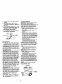
Owner's Manual
]CRRFTSMRN'J
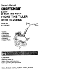
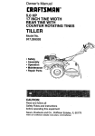
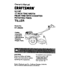
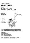
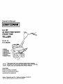
5.5 HP
24 INCH TINE WIDTH
FRONTTINE
TILLER
Model No.
/
917.292480
•
•
•
•
•
•
Safety
,_--_ _[ ("
_.4_
Assembly
___/_7_/_
Operation
,_-w<..
_/
Maintenance
('_,_'_,_
Espa6ol
"--_'_J_(
([ _//_f/'_
Repair Parts
_/-_ _<__ .=_-_(_.o.))
differently
built engines.
Beforeoperates
you start the
This
productfrom
haspreviously
a low emission
engine which
engine, read and understand this Owner's Manual.
CAUTION:
Read and follow all Safety
Rules and Instructions before
operating this equipment.
Sears, Roebuck
and Co., Hoffman Estates, II 60179
Visit our Craftsman website:www.sears.com/craftsman
Maintenance .......................................
11
Service and Adjustments .................... 13
Storage ..........................................
3& 16
Troubleshooting
................................. 17
illustrated Parts List ............................ 36
Parts Ordering ..................... Back Cover
Warranty ...............................................
2
Safety Rules .........................................
2
Product Specifications .......................... 4
Assembly ..............................................
5
Operation .........................................
3&7
Maintenance Schedule ...................... t 1
LIMITED ONE YEAR WARRANTY
ON CRAFTSMAN
TILLER
For one (1) year from date of purchase, when this Craftsman Tiller is maintained,
lubricated, and tuned up according to the operating and maintenance instructions in
the owner's manual, Sears will repair free of charge any defect in material or workmanship.
This Warranty does not cover;
• Expendable items which become worn during normal use, such as tines, spark
plugs, air cleaners and belts.
• Repairs necessary because of operator abuse or negligence, including bent
crankshafts and the failure to maintain the equipment according to the instructions
contained in the owner's manual.
• If this Craftsman Tiller is used for commercial or rental purposes, this Warranty
applies for only thirty (30) days from the date of purchase.
Warranty service is available by returning the craftsman power mower to the nearest
sears service center/deparfment in the united states. This warranty applies only while
this product is in use in the united states,
This Warranty gives you specific legal rights, and you may also have other rights which
vary from state to state.
SEARS, ROEBUCKAND
CO., D/817WA, HOFFMAN ESTATES, IL 60179
IMPORTANT: This cutting machine is capable of amputating hands and feet and
throwing objects. Failure to observe the following safety instructions could result in
serious injury or death.
TRAINING
• Read the Owner's Manual carefully, Be
thoroughly familiar with the controls
and the proper use of the equipment,
Know how to stop the unit and disengage the controls quickly.
• Never allow children to operate the
equipment. Never allow adults to
operate the equipment without proper
instruction,
• Keep the area of operation clear of all
persons, particularly small children,
and pets,
PREPARATION
• Thoroughly inspect the area where the
equipment is to be used and remove all
foreign objects.
• Disengage all clutches and shift into
neutral before starting the engine
(motor).
o, Do not operate the equipment without
wearing adequate outer garments.
Wear footwear that will improve footing
on slippery surfaces.
• Handle fuel with care; it is highly
flammable.
• Use an approved fuel container.
• Never add fuel to a running engine or
hot engine.
• Fill fuel tank outdoors with extreme
care. Never fill fuel tank indoors.
• Replace gasoline cap securely and
clean up spilled fuel before restarting.
2
• Use extensioncords and receptacles
as specifiedby the manufacturer for all
unitswith electricdrive motorsor
electricstartingmotors,
• Never attemptto make any adjustments
while the engine (motor) is running
(except where specificallyrecommended by manufacturer).
OPERATION
• Do not put hands or feet near or under
rotatingparts.
• Exerciseextreme caution when
operatingon or crossinggravel ddves,
walks, or roads. Stay alert for hidden
hazards or traffic.Do not carP/passengers.
• Afterstdkinga foreignobject,stop the
engine (motor),remove the wire from
the spark plug,thoroughlyinspectthe
tiller for any damage, and "repairthe
damage before restartingand operating the tiller.
• Exemisecautionto avoid slippingor
falling.
• If the unitshouldstartto vibrate
abnormally,stop the engine (motor)
end check immediatelyfor the cause.
Vibrationis generallya warningof
trouble.
• Stop the engine (motor) when leaving
the operatingposition.
• Take all possibleprecautionswhen
leaving the machineunattended.
Disengage the tines, shift intoneutral,
and stop the engine.
• Beforecleaning, repaidng,or inspecting, shut off the engine and make
certainall movingparts have stopped.
Disconnectthe spark plug wire, and
keep the wire away from the plug to
preventaccidental starting.Disconnect
the cord on electricmotors.
• Do not runthe engine indoors;exhaust
fumes are dangerous.
• Never operate the tiller withoutproper
guards,plates, or othersafety protective devicesin place.
• Keep childrenand pets away.
• Do not overload the machine capacity
by attempting to till too deep at too fast
a rate.
• Never operate the machine at high
speeds on slippery surfaces. Look
behind and use care when backing.
• Never allow bystanders near the unit.
• Use only attachments end accessories
approved by the manufacturer of the
tiller.
• Never operate the tiller without good
visibility or light.
• Be careful when tilling in hard ground.
The tines may catch in the _]round and
propel the tiller forward. If this occurs,
let go of the handlebars and do not
restrain the machine.
MAINTENANCE
AND STORAGE
• Keep machine, attachments, end
accessories in safe working condition.
• Check shear pins, engine mounting
bolts, and other bolts at frequent
intervals for proper tightness to be sure
the equipment is in safe working
condition.
• Never store the machine with fuel in the
fuel tank inside a building where
ignition sources are present, such as
hot water and space heaters, clothes
dryers, and the like, Allow the engine to
cool before storing in any enclosure.
• Always refer to the operator's guide
instructions for important details it the
tiller is to be stored for an extended
period.
ALook for this symbol to point out
important safetyprecautions, It means
GAUTIONH! BECOMEALERTlit YOUR
SAFETY IS INVOLVED.
ACAUTION: Always disconnect spark
plug wire and place wire where it cannot
contact spark plug in order to prevent
accidental starting when setting up,
transporting, adjusting or making repairs.
AWARNING: Engine exhaust, some of its
constituents, and cedain vehicle components contain or emit chemicals known to
the State of California to cause cancer
and birth defects or other reproductive
harm.
PRODUCT SPECIFICATIONS
GASOLINE
C,APACITY:
3 QTS
UNLEADED
REGULAR
OIL(API-SF-SJ):
SAE 30
CAPACITY:20 OZ,) (ABOVE32°F)
SAE 5W-30
SPARKPLUG:
(BELOW 32°F)
CHAMPION
(GAP: .030')
RJ19LM OR J19LM
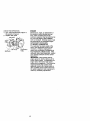
:ONGRATULATIONS on your purchase
of a Sears Tiller.It has been designed,
engineered and manufacturedto give
you the best possibledependabilityand
performance.
Should you experience any problems
you cannot easily remedy,please
contacta Sears or other qualified
Service Center. We have competent,
well-trainedtechniciansand the proper
tools to serviceor repairthis unit.
Please read and retainthis manual. The
instructionswill enable you to assemble
and maintainyour tiller properly.Always
observethe "SAFETY RULES".
Yournew tiller has been assembledat
the factory with exceptionof those parts
left unassembledfor shippingpurposes.
To ensure safe and properoperationof
your tillerall parts and hardware you
assemble mustbe tightenedsecurely.
Use the correcttoolsas necessaryto
insure propertightness.
CUSTOMER
RESPONSIBILITIES
• Read and observe the safety rules.
• Follow a regular schedule in maintaining, cadng for and using your tiller.
• Follow the instructions under the
"Customer Responsibilities" and
"Storage" sections of this Owner's
Manual.
_WARNING:
This unit is equipped with
an internal combustion engine and
should not be used on or near any
unimproved forest-covered, brushcovered or grass covered land unless the
engine's exhaust system is equipped with
a spark arrestsr meeting applicable local
or state laws (if any). If a spark arrester is
used, it should be maintained in effective
working order by the operator.
In the state of California the above is
required by law (Section 4442 of the
California Public Resources Code),
Other states may have similar laws.
Federal laws apply on federal lands. A
spark arrester for the muffler is available
through your nearest Sears service
center (See REPAIR PARTS section of
this manual).
These accessorieswere available when the tillerwas pumhased. They are also
available at mostSears Retail outletsand Service Centers. Most Sears Stores can
order repairparts for you when you providethe model numberof your tiller.
ENGINE
f
TILLER MAINTENANCE
BELT
TINES
SHEAR PIN
i
4
HAIRPIN CLIP
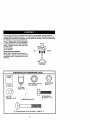
Your new tiller has been assembled at the factory with exception of those parts left
unassembled for shipping purposes. To ensure safe and proper operation of your tiller
all parts and hardware you assemble must be tightened securely. Use the correct tools
as necessary to Ensureproper tightness.
TOOLS
REQUIRED
FOR ASSEMBLY
FRONT
A socket wrench set will make assembly
easier. Standard wrench sizes are listed.
(1) Utility knife
(1) Pair of pliers
(2) 1/2 Wrench
OPERATOR'S
POSITION
When right or left hand is mentioned in
this manual, it means when you are in the
operating position (standing behind tiller
handles).
LEFT
_
RIGHT
OPERATOR'S
POSITION
CONTENTS
OF HARDWARE
PACK
©
©
(2) Flange Locknuts
5/16-18UNC
(1) Manual
-©
(2) Lock
Washers
(1) Plastic
Cable
Clip
i
5/16
(1) Bottle Engine Oil
(2) Carriage
Bolts
5/16-18
5
UNC x 2-3/8
Gr. 5
(2) Hex Nuts
5/16-16
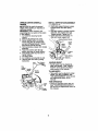
UNPACK CARTON & INSTALL
HANDLE
• iLCAUTION:Be carefulof exposed
staples when handlingor disposingof
cadoning material.
IMPORTANT: When unpackingand
assemblingtiller,be carefulnot to stretch
or kink cable(s).
1. Cut cable ties securinghandle
column.
2. Remove all packingfrom cation.
3. Secure handle columnto handle
mountusingtwo (2) carriage bolts
and two (2) flange Iocknuts. Tighten
both flange Iocknutssecurely.
4. Remove packing material from handle
assembly.
5. Route tine controlcable through
plasticcable clip on handle column.
6, Insertplasticcable clip into hole in
handle column.
7, Cut away carton.
8. Cut cable ties securingtillerto skid.
9. Remove tillerfrom skid by pulling
backwards.
INSTALL DEPTH STAKE ASSEMBLY
1. Loosen nut "A".
2. Insert stake suppod between engine
bracket halves with stake spring
down.
3. Bolt stake support to engine brackets
with bolts, lock washers and nuts.
Tighten securely. Tighten nut "A".
4. Depth stake must move freely. If it
does not, loosen support bolt.
ine BracketHalves
"A"
Support
Bolt
"Stake Spring
.ock Washers,
and hex Nuts
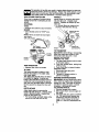
HANDLE HEIGHT
• Handle height may be adjustedto
better suit operator. (See "HANDLE
HEIGHT" in the Service and Adjustments sectionof this manual).
TILLING WIDTH
• Tillingwidthmay be adjustedto better
handle your tillingconditions(See
"FINE ARRANGEMENT_ in the Service
and Adjustmentssection of this
manual).
TINE OPERATION
Tine
C_tro_
- Handle
Cable_i
_
Depth
Column
" _'Flange
Locknut
6
• Check tine operationbeforefirst use.
(See "FINE OPERATION CHECK"in
the Serviceand Adjustmentssectionof
this manual),
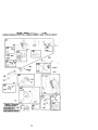
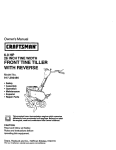
KNOW YOUR TILLER
READ THIS OWNER'S MANUAL AND SAFETY RULES BEFORE OPERATING
YOUR TILLER
Compare the illustrationswith your tillerto familiarizeyourselfwith the locations of
various controls and adjustments. Save this manual for future reference.
TILUNC;
F_WARD
_£UTr_L
REvEqs_
CAUTX_N
ENGINE
_:_NE
fAST
SLOW
CHOKE
_UEL
_L
ST_
_)
FonNardTine
Control
Choke Control
Control
Tine Shield
Depth
Recoil
Handle
Our tillers conform to the safety standards of the American National Standards Institute.
FORWARD TINE CONTROL - Engages
tines in forward direction,
CHOKE CONTROL - Used when starting
a cold engine.
THROTTLE CONTROL - Used to control
engine speed.
DEPTH STAKE - Controls forward speed
and the depth at which tiller will dig.
RECOIL STARTER HANDLE - Used to
start the engine.
Theoperation
ofanytillercanresultinforeignobjects
thrown
intotheeyes
whichcanresultinsevere
eyedamage.
Awayswearsafety
glasses
oreye
shields
beforestarting
yourtillerandwhiletilling.Werecommend
a wide
visionsafetymaskoverspectacles
orstandard
safety
glasses.
HOWTOUSEYOURTILLER
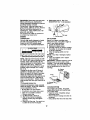
WHEELS
Knowhowtooperate
allcontrols
before Adjust wheels by removingthe hairpin
adding
fuel and oil or attempting to start
clip and clevis pin. Change wheel
engine.
STOPPING
TINES
position. Replace the hairpinclip and
clevis pin.
• For normaltilling,set wheels at the
secondor third holefrom the top.
\
HairpinClipand
• Release Une control to stop movement.
ENGINE
• Move throttle control to =STOP" position.
NOTE: Never use choke to stop engine.
Tine Control
"Off" (UP) Position
"On" (DOWN) Position _
Depth
Stake
HairpinClip
and Clevis Pin
"
TO TRANSPORT
ACAUTION:
Before lifting or transporting
allow tiller engine and muffler to cool.
Disconnect spark plug wire. Drain
gasoline from fuel tank.
AROUND THE YARD
1. Tip depth stake forward until it is held
by the stake spdng.
2. Push tiller handles down, raising tine._
off the ground.
3. Push or pull tiller to desired location.
AROUND TOWN
Contmt
Chokq
Control
TINE OPERATION
• Squeeze Une control to handle.
TILLING
1. Disconnect spark plug wire.
2. Drain fuel tank.
3. Transport in upright position to
prevent oil leakage.
BEFORE STARTING ENGINE
The speed and depth of tilling is regulated by the position of the depth stake
and wheel height.
The depth stake should always be below
the wheels for digging, it serves as a
brake to slow the tiller's forward motion to
enable the tines to penetrate the ground.
Also, the more the depth stake is lowered
into the ground the deeper the tines will
dig.
IMPORTANT: Be very careful not to allow
dirt to enter the engine when checking or
adding oil or fuel. Use clean oil and fuel
and store in approved, clean, covered
containers, use clean fill funnels,
FILL ENGINE WITH OIL
DEPTH STAKE
1. Remove hangtag from engine.
2. With engine level, remove engine oil
filler plug.
3. Fill engine with oil to point of overflow
ing. For approximate capacity see
=PRODUCT SPECIFICATIONS" on
page 4 of this manual. All oil must
meet A.P.I. Service Classification SFSJ.
Adjust depth stake by removing the
hairpin clip and clevis pin. Change depth
stake to desired position. Replace the
clevis pin and hairpin clip.
• For normal tilling, set depth stake at the
second or third hole from the top.
8
4, Tilt tiller back on its wheels and then
re-level.
5, With engine level, refill to point of
overflowing if necessary. Replace oil
filler plug.
• For cold weather operation you should
change oil for easier starting (See "OIL
VISCOSITY CHART" in the Maintenance section of this manual).
• To change engine oil, see the Maintenance section of this manual.
Oil Leve_
TO START
ENGINE
_CAUTION:
Keep fine control in "OFF"
position when starting engine.
When starting engine for the first time or if
engine has run out of fuel, it will take
extra pulls of the recoil starter to move
fuel from the tank to the engine.
1. Make sure spark ptug wire is properly
connected.
2. Place throttle control in "FAST"
position.
3. Move choke control to full "CHOKE"
position. Grasp recoil starter handle
with one hand and grasp tiller handle
with other hand, Pull rope out slowly
until engine reaches start of compression cycle (rope will pull slightly
harder at this point).
4. Pull recoil starter handle quickly. Do
not let starter handle snap back
against starter. Repeat if necessary.
NOTE: If engine fires but does not start,
move choke control to half choke position.
Pull recoil starter handle until engine
starts.
5. When engine starts, slowly move
choke control to "RUN" position as
engine warms up.
NOTE: A warm engine requires less
choking to start.
6. Move throttle control to desired
running position.
7. Allow engine to warm up for a few
minutes before engaging fines.
NOTE: If at a high altitude (3000 feet) or
in cold temperatures (below 32°F), the
carburetor fuel mixture may need to be
adjusted for best engine performance.
See "TO ADJUST CARBURETOR" in the
Service and Adjustments section of this
manual.
NOTE: If engine does not start, see
troubleshooting points.
_Plug
ADD GASOLINE
• Fill fuel tank. Use fresh, clean, regular
unleaded gasoline. (Use of leaded
gasoline will increase carbon and lead
oxide deposits and reduce valve life.)
IMPORTANT; When operating in temperatures below 32°F(0°C), use fresh, clean,
winter grade gasoline to help insure good
cold weather starting.
_I_,WARNING: Experience indicates that
alcohol blended fuels (called gasohol or
using ethanol or methanol) can attract
moisture which leads to separation and
formation of acids during storage. Acidic
gas can damage the fuel system of an
engine while in storage. To avoid engine
problems, the fuel system should be
emptied before storage of 30 days or
longer. Drain the gas tank, start the
engine and let it run until the fuel lines
and carburetor are empty. Use fresh fuel
next season, See Storage section of this
manual for additional information. Never
use engine or carburetor cleaner products in the fuel tank or permanent
damage may occur.
_CAUTION:
Fill to within 1/2 inch of top
of fue! tank to prevent spills and to allow
for fuel expansion. If gasoline is accidentally spilled, move machine away from
area of spill. Avoid creating any source of
ignition until gasoline vapors have
disappeared.
Do not overfill. Wipe off any spilled oil or
fuel. Do not store, spill or use gasoline
near an open flame.
Spa_ Plug
r_ __
',Jf_÷
Choke \
Control
_
__
_"
Starter---""_ °_:_
9
Thro_e
Control
BREAKING IN YOUR TILLER
Break-inyour belt(s), pulleys and tine
control beforeyou actuallybegin tilling.
• Start engine,tip tines off groundby
pressinghandles down and engage
line controlto startline rotation.Allow
tines to retate for five minutes.
• Check tine operationand adjustif
necessary. See "TINEOPERATION
CHECK"in the Service and Adjustmentssectionof this manual.
TILLING HINTS
4gl,
CAUTION: Until you are accustomedto
handlingyourtiller,start actual field use
with throttlein slow position.
To help tiller moveforward, lift up the
handlesslightly(thus liftingdepth stake
out of ground).To slow down the tiller,
press down on handles.
It you are strainingor tilleris shaking,the
wheels and depthstake are not set
propedyin the soil being tilled.The
propersettingof the wheels and depth
stake is throughtrialand error and
depends uponthe soil condition. (The
harder or wetterthe ground,the slower
the engine and line speed needed. Under
these poor conditions,at fast speed the
tillerwill run and jumpover the ground).
A propedyadjusted tiller will dig with little
effortfrom the operator.
• Tillingis digginginto, turningover, and
breakingup packed soilbefore
planting. Loose, unpackedsoil helps
root growth.Best tillingdepth is 4"-6".
A tillerwill also clear the soil of unwanted vegetation.The decomposition
of this vegetablematter endchesthe
so=l. Dependingon the climate (rainfall
and wind), it may be advisableto till the
soilat the end of the growingseason to
further conditionthe soil.
• Soil conditionsare importantfor proper
tilling.Tines will not readilypenetrate
dry, hard soilwhich may contributeto
excessive bounce and difficulthandling
of your tiller.Hard soil shouldbe
moistenedbefore tilling;however,
extremelywet soil will "bell-up"or
clumpduringtilling.Wait untilthe soil is
less wet in orderto achieve the best
results.When tillingin the fall, remove
vines and long grassto preventthem
from wrappingaround the line shaft
and slowingyour tillingoperation.
* You will find tilling much easier, if you
leave a row untilled between passes.
Then go back between tilted rows
There are two reasons for doing this.
First, wide turns are much easier to
negotiate than about-faces. Second,
the tiller won't be pulling itself, and
you, toward the row next to it.
• Set depth stake and wheel height for
shallow tillingwben working extremely
hard soil or sod. Then work across the
first cuts at normal depth.
CULTIVATING
Cultivating is destroyingthe weeds
between rows to preventthemfrom
robbingnourishmentand moisturefrom
the plants.At the same time, breaking up
the upper layer of soilcrust willhelp
retainmoisturein the soil. Best digging
depthis 1"-3".
• You willprobablynot need to use the
depthstake. Begin by tippingthe depth
stake forward untilit is held by the
stake spdng.
• Cultivateup and downthe rows at a
speed whichwill allowtines to uproot
weeds and leave the ground in rough
condition,promotingno further growth
of weeds and grass.
lO
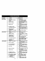
MAINTENANCE
SCHEDULE
FILL IN DATES
AS YOU COMPLETE
REGULAR SERVICE
Check Engine OII Level
v'
v"
Change Engine Oil
Oil Pivot PoinLs
Inspect Spark Attester / Muffler
Inspect Air Screen
Cle_n or Replace Air Cleaner Cartridge
I/2
Clean Engine Cylinder Fins
I1_
Replace Spark Plug
I/
1 - Cf_angemote often when operal_ngunder a heavy load ot in high ambienl ternpefatures.
2 • Service more often when operating in dirty or dusty conditions
GENERAL
LUBRICATION CHART
RECOMMENDATIONS
The warranty on this tiller does not cover
items that have been subjected to
operator abuse or negligence. To receive
full value from the warranty, the operator
must maintain tiller as instructed in this
manual.
Some adjustments will need to be made
periodically to properly maintain your
tiller.
All adjustments in the Service and
Adjustments section of this manual
should be checked at least once each
season.
• Once a year you should replace the
spark plug, clean or replace air filter,
and check tines and belts for wear. A
new spark plug and clean air filter
assure proper air-fuel mixture and help
your engine run better and last longer.
BEFORE
* _ne Contml
*" Engine
EACH USE
" SAE 30 OR 10W-30 Motor Oil
** Refer to Maintenance =ENGINE" section
1. Check engine oil level.
2. Check tine operation.
3. Check for loose fasteners.
LUBRICATION
Keep unit well lubricated (See =LUBRICATION CHART").
11
_CAUTION: Disconnectspark plug wire
before performingany maintenance
(except carburetoradjustment)to prevent
accidentalstartingof engine.
Prevent fires! Keep the enginefree of
grass, leaves, spilledoil, or fuel. Remove
fuel from tank beforetippingunitfor
maintenance. Clean mufflerarea of all
grass,dirt, and debris.
Do not touch hot muffleror cylinderfins
as contactmay cause burns.
ENGINE
LUBRICATION
Use only high qualitydetergentoil rated
with API serviceclassificationSF-SJ.
Select the oil'sSAE viscositygrade
accordingto your expected temperature.
SAEVISCOSITY
GRADES
NOTE: Although multi-viscosity oils (5W30, 10W-30, etc.) improve starting in cold
weather, these multi-viscosity oils will
result in increased oil consumption when
used above 32°F (0°C). Check your
engine oil level more frequently to avoid
possible engine damage from running
low on oil.
Change the oil after every 50 hours of
operation or at least once a year if the
tiller is not used for 50 hours in one year.
Check the crankcase oil level before
starting the engine and after each five (5)
hours of continuous use. Add SAE 30
motor oil or equivalent. Tighten oil filler
plug securely each time you check the oil
level.
TO CHANGE ENGINE OIL
Determine temperature range expected
before oil change. All oil must meet API
service classification SF-SJ.
• Be sure tiller is on level surface.
• Oil will drain more freely when warm.
• Catch oil in a suitable container.
1. Remove drain plug.
2. Tip tiller fonvard to drain oil.
3. After oil has drained completely,
replace oil drain plug and tighten
securely.
4. Remove oil filler plug. Be careful not
to allow dirt to enter the engine.
5. Refillengine with oil. See =FILL
ENGINE WITH OIL" in the Operation
Oil
Drain
Rug,
Oil Filler Plug
AIR CLEANER
Service air cleaner cartridgeevery
twenty-fivehours,more often if engine is
used in very dustyconditions.
I. Loosen air cleaner screw.
2. Remove air cleaner cover.
3. Carefullyremove air cleaner cartddge.
Be careful. Do not allowdirt or debris
to fall intocarburetor.
4. Clean by tappinggentlyon a flat
surface.
NOTE: If verydirtyor damaged,replace
cartridge.
5. Clean and replace cover. Tighten
screw securely.
ACAUTION: Petroleumsolvents,such as
kerosene, are not to be used to clean
cartridge. They may cause detedoration
of the cartridge. Do not oil cartridge, Do
not use pressudzedair to clean or dry
cartridge.
Air Cleaner
Cover
.Screw.
COOLING SYSTEM
Your engine is air cooled. For proper
engine performance and long life keep
your engine clean.
• Clean air screen frequently using a
stiff-bdstled brush.
• Remove blower housing and clean as
necessary.
• Keep cylinder fins free of dirt and chaff.
12
Muffler
Cynr}der Fins
\
\
BIowsr
Houe o
_] ! _t_/,_/Air
Screen
Spark plug type and gap setting are
shown in "PRODUCT SPECIFICATIONS"
on page 4 of this manual.
TRANSMISSION
Your transmission is sealed and will not
require lubrication unless serviced.
CLEANING
MUFFLER
Do not operate tiller without muffler. Do
not tamper with exhaust system. Damaged mufflers or spark arresters could
create a fire hazard. Inspect periodically
and replace if necessary. If your engine is
equipped with a spark arrester screen assembly, remove every 50 hours for cleaning and inspection. Replace if damaged.
SPARK PLUG
Replace spark plugs at the beginning of
each tilling season or after every 50
hours of use, whichever comes first.
_kCAUTION:
Disconnect spark plug wire
from spark plug and place wire where it
cannot come into contact with plug.
TILLER
TO ADJUST HANDLE HEIGHT
Factory assembly has provided lowest
handle height. Select handle height best
suited for your tilling conditions. Handle
height wil! be different when tiller digs
into soil,
1. If a higher handle height is desired,
loosen the four nuts securing handle
panel to engine brackets.
2. Slide handle panel to desired location.
3. Tighten the four nuts securely.
Do not clean your tiller when the engine
and transmission are hot. We do not
recommend using pressurized water
(garden hose, etc.) to clean your unit
unless the gasket area around the
transmission and the engine muffler, air
filter and carburetor are covered to keep
water out. Water in engine will shorten
the useful life of your tiller.
• Clean engine, wheels, finish, etc. of all
foreign matter.
• Keep finished surfaces and wheels free
of all gasoline, oil, etc.
• Protect painted surfaces with automotive type wax,
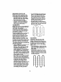
TINE ARRANGEMENT
Yourouter tinescan be assembledin
several differentways to suit yourtillingor
cultivatingneeds.
_]kCAUTION: ]3nesare sharp. Wear
glovesor other protectionwhen handling
tines.
NORMALTILLING - 24" PATH
• Assemble holes "A" in tine hubs to
holes "B" in tine shaft.
_
Engine Brackets
Handle
ClevisPin
HairpinClip
Outer Tins
_lnner
MID-WIDTH TILLING o22" PATH
• Assemble holes "A" in tine hubs to
holes "C" in tine shaft,
nel
.
uts(Also 2
on Left Side
of Tiller
13
Tine
NARROW TILLING/CULTIVATING
12-3/4" PATH
• Remove outer tines.
Ioo
-
NOTE: If =ON" position check requtred
adjustment, recheck "OFF" position
adjustment to insure tines do not rotate
when control is =OFF" (up).
"nneControl"OFF" Position
ool
"lineControlCable
NOTE: When reassembling outer tines,
be sure right tine assembly (marked =R")
and left tine assembly (marked %") are
mounted to correct side of tine shaft.
TINE OPERATION
CHECK
AWARNING:
Disconnect spark plug wire
from spark plug to prevent starting while
checking tine operation.
For proper tine operation, tine control
lever must be against control body and all
slack removed from inner wire of control
cable when control is in the "OFF" (up)
position,
If lever and cable are loose, loosen cable
clip at lower end of cable. Pull up on
cable to remove slack, without extending
spring on end of cable, and retighten
cable clip.
FINAL CHECK "OFF" POSITION
\
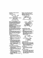
TO REMOVE BELT GUARD
1. Remove screws from side of belt
guard.
2. Pull bolt guard out and away from unit.
3. Replace belt guard by reversing
above procedure. Be sure slot in
bottom of belt guard is under head of
tine shield bolt and all nuts are
tightened securely.
1. With tine control "OFF" (up), push
down on handle to raise tines off the
ground.
Scrsw
2. Slowly pull recoil starter handle while
observing tines. Tines should not
rotate,
Screw
3. If tines rotate, inner wire of control
cable is too tight which is extending
:_._ /"_)'_
Screw
lower spring and engaging tines.
TO REPLACE V-BELT
Loosen cable clip and push down on
cable only enough to relieve spring
Replace V-belt if it has stretched considtension. Tighten cable clip,
erably or if it has cracks or frayed edges,
4, Recheck in =OFF" position and adjust
1. Belt guard must be removed to service
if necessary.
belt. See "TO REMOVE BELT
GUARD" in this section of manual
FINAL CHECK "ON" POSITION
BELT REMOVAL
5. With fine control "ON" (held down to
handle) push down on handle to raise
2. Remove V-belt from transmission
tines off the ground.
pulley first and then from engine
6, Slowly pull recoil starter handle while
pulley. •
observing tines. Tines should rotate
BELT
REPLACEMENT
forward.
3.
Install
new V-beif to engine pulley first
7. If tines do not rotate, inner wire of
then to transmission pulley. Be sure
control cable is too loose. Loosen
belt is positioned on inside groove of
cable clip and pull cable up to remove
both pulleys, inside all belt guides and
slack and retighten clip.
rests on idler pulley.
8. Recheck in =ON" position and adjust if
14
necessary.
CHECK TINE OPERATION
4. See "TINE OPERATION
this section of manual.
5. Replace belt guard
Belt Guide
CHECK" in
Engine
\
Idler Pulley
Belt'
Transmission
Pulley
ENGINE
Maintenance, repair, or replacementof
the emissioncontroldevices and systems, whichare being done at the
customers expense,may be performedby
any non-roadangina repair establishmentor individual.Warranty repairsmust
be performed by an authorizedengine
manufacturer's service outlet.
TO ADJUST CARBURETOR
The carburetorhas been preset at the
factoryand adjustmentshouldnot be
necessary. However,engine performancecan be affectedby differencesin
fuel,temperature, altitudeor load. If the
carburetordoes need adjustment, contact
yournearest authorizedservice center/
department
IMPORTANT: Never tamper withthe
engine governor, whichis factoryset for
properengine speed. Overspeedingthe
engine above the factory high speed
setting can be dangerous. If you thinkthe
engine-governedhigh speed needs
adjusting,contactyour nearest sears or
otherqualifiedservice center which has
the properequipmentand experience to
make any necessaryadjustments.
15
Immediately prepare your tiller for storage
at the end of the season or if the unit will
not be used for 30 days or more.
ACAUTION:
Never store the tiller with
gasoline in the tank inside a building
where fumes may reach an open flame or
spark. Allow the engine to cool before
storing in any enclosure.
TILLER
1. Clean entire tiller (See "CLEANING" in
the Maintenance sectionofthis
manual).
2. Inspect and replace belts, if necessary
(See belt replacement instructions in
the Service and Adjustments section
of this manual).
3. Lubricate as shown in the Maintenance section of this manual.
4. Be sure that all nuts, bolts and screws
are securely fastened. Inspect moving
parts for damage, breakage and wear.
Replace if necessary.
5. Touch up all rusted or chipped paint
surfaces; sand lightly before painting.
ENGINE
FUEL SYSTEM
IMPORTANT: It is important to prevent
gum deposits from forming in essential
fuel system parts such as the carburetor,
luel filter, fuel hose, or tank during
storage, also, experience indicates that
alcohol blended fuels (called gaaohol or
using ethanol or methanol) can attract
moisture which leads to separation and
iormation of acids during storage. Acidic
_as can damage the fuel system of an
_=nginewhile in storage.
1. Drain the fuel tank.
2. Start the engine and let it run until the
fuel lines and carburetor are empty.
, Never use engine or carburetor cleaner
products in the fuel tank or permanent
damage may occur.
• Use fresh fuel next season.
NOTE: Fuel stabilizer is an acceptable
alternative in minimizing the formation of
fuel gum deposits during storage. Add
stabilizer to gasoline in fuel tank or
storage container. Always follow the mix
ratio found on stabilizer container. Run
engine at feast 10 minutes after adding
stabilizer to allow the stabilizer to reach
the'carburetor. Do not drain the gas tank
and carburetor if using fuel stabilizer.
ENGINE OIL
Drain oil (with engine warm) and replace
with clean oil. (See "ENGINE" in the
Maintenance section of this manual).
CYLINDER
1. Remove spark plug.
2. Pour I ounce (29 ml) of oil through
spark plug hole into cylinder.
3. Pull starter handle slowly several
times to distribute oil.
4. Replace with new spark plug.
OTHER
• Do not store gasoline from one seasor
to another.
• Replace your _asoline can if your can
starts to rust. Rust and/or dirt in your
gasoline will cause problems.
• If possible, store your unit indoors and
cover it to give protection from dust an
dirt.
• Cover your unit with a suitable protective cover that does not retain moisturr
Do not use plastic. Plastic cannot
breathe which allows condensation to
form and will cause your unit to rust.
IMPORTANT: Never cover tiller while
engine and exhaust areas are still warm.
16
PROBLEM
Will not start
CORRECTION
CAUSE
1. Out of fuel.
2. Engine not "CHOKED"
properly.
3. Engine flooded,
4. Dirty air cleaner.
5. Wate'r in fuel.
6. Clogged fuel tank.
7. Loose spark plug wire.
8. Bad spark plug or
improper gap.
9. Carburetor out of adjustment.
Hard to start
1. Throttle control not set
properly.
2. Dirty air cleaner.
3. Bad spark plug or
improper gap.
4. Stale or dirtyfuel.
5. Loose spark plug wire.
6. Carburetor out of
adjustment.
Loss of power
1. Engine is overloaded.
2. Dirty air cleaner,
3. Low oil level/dirty oil.
4. Faulty sparkplug,
5. Oil in fuel.
6. Stale or dirty fuel.
7. Water in fuel.
8. Clogged fuel tank.
9. Spark plug wire loose.
10. Dirty engine air screen.
lf. Dirty/clogged muffler.
12. Carburetor out of
adjustment.
13. Poor compression.
17
1. Fill fuel tank.
2. See "TO START ENGINE"
in the Operation section.
3. Wait several minutes before
attempting to start.
4. Clean or replace air cleaner
cartridge.
5. Drain fuel tank and carburetor, and refill tank with fresh
gasoline.
6. Remove fuel tank and clean.
7. Make sure spark plug wire is
seated properly on plug.
8. Replace spark plug or adjust
gap.
9. Make necessary adjustments.
1. Place throttlecontrolin
"FAST" position,
2. Clean or replaceair cleaner
cartridge.
3. Replace spark plug or adjust
gap.
4. Drain fuel tank and refill
with fresh gasoline.
5, Make sure spark plug wire is
seated properlyon plug.
6. Make necessary adjustments.
1. Set depth stake and wheels
for shallower tilling.
2. Clean or replace air cleaner
cartridge.
3. Check oil level/change oil.
4. Clean and regap or change
spark plug.
5. Drain and clean fuel tank
and refill, and clean carburetor.
6. Drain fuel tank and refill with
fresh gasoline.
7. Drain fuel tank and carburetor, and refill tank with fresh
gasoline.
8. Remove fuel tank and clean.
9. Connect and tighten spark
plug wire.
10.Clean engine air screen.
11. Clean/replace muffler.
12. Make necessary adjustments.
13. Contact a Sears or other
qualified service center.
PROBLEM
Engine
overheats
CAUSE
CORRECTION
1. Low oil level/dirty oil.
2. Dirty engine air screen.
3. Dirty engine.
4. Partially plugged muffler.
5. Improper carburetor
adjustment.
Excessive
bounce/dlfficult
handling
I. Ground too dry and hard.
2. Wheels and depth stake
incorrectly adjusted,
1. Check oil level/change oil.
2. Clean engine air screen.
3. Clean cylinder fins,
airscreen, muffler area.
4. Remove and clean muffler.
5. Adjust carburetor to richer
position.
1. Moisten ground or wait
for more favorable soil
conditions.
2. Adjust wheels and depth
stake.
Soil balls up or
clumps
t. Ground too wet.
1. Wait for more favorable
soil conditions.
Engine runs but
tiller won't move
t. Tine control is not
1. Engage tine control.
Engine runs but
labors when
tilling
engaged.
2. V-belt not correctly
adjusted.
3. V-belt is off pulley(s).
I. Tilling too deep.
2. Throttlecontrolnot
propedy adjusted.
3. Carburetorout of
adjustment,
18
2. Inspect/adjust V-belt.
3, Inspect V-belt.
1. Set depth stake for shallower tilling.
2. Check throttle control setting.
3. Make necessary adjustments.
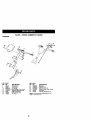
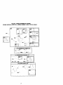
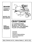
TILLER -- MODEL NUMBER 917.292480
HANDLES
18
KEY
NO,
1
3
12
13
14
18
19
20
PART
NO,
137118
9_6R
98000129
STD533107
110514X
3066J
151229
154805
KEY
NO.
21
29
35
36
37
38
DESCRIPTION
Panel,Control
Grip,Handle
Nut, Flange
Bolt, Carriage 5/16-18x3/4
Assembly, Panel and Tube
Cable, Tine Control
Lever, Control, Tine
Pin, Pivot
PART
NO.
12000027
12000059
72010520
73970500
165197
152094
DESCRIPTION
Ring,Clip
Retainer, Ring
Bolt 5/16-18 x 2-1/2
Locknut, Flange 5/16-18 UNC
Clip,Cable
Assembly, Handle Column
NOTE: All component dimensions
inches. 1 inch = 25,4 mm
36
given in U.S.
TILLER- - MODEL NUMBER 917.292480
BELT GUARD AND PULLEY ASSEMBLY
KEY
NO.
PART
NO.
DESCRIPTION
1
2
3
4
5
6
7
8
9
10
11
12
23230506
130812
17211006
74610812
17490440
174898
170488
139155
165768X558
109227X
9484R
9180R
Screw Set 5/16-18 x 3/8 Patch
Sheave, Engine
Screw, Tap Hex Head
Bolt, Hex Head 1/2-20 x 3/4
Bolt, Thd Roller 1/4-20 x 2-1/2
Shield, Inner Belt Guard
Screw Hex Wsh Hd #8-18 x 1/2
Spacer Split
Guard, Belt
Pad, Idler
Clip,Cable
V-Belt
KEY
NO.
PART
NO.
DESCRIPTION
13
14
16
17
18
19
20
21
25
12000028
151223
12000036
STD541237
161806
175377
STD52.3712
106968X
73350500
Ring, Retainer
Sheave,Transmisison
Ring, Klip
Nut, Hex, Jam 3/8-16
Pulley, Idler
Arm, Idler
Bolt, Hex Head 3/8-16 x 1,114
Shaft, Idler Arm
Nut, Hex, Jam 5/16-18
NOTE: All _omponent dimensions
inches. I inch = 25.4 mm
"4'7
given in U.S.
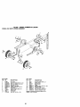
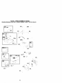
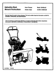
TILLER - - MODEL NUMBER 917.292480
WHEEL AND DEPTH STAKE ASSEMBLY
8
7
6
7
17
19 20
20
19
17
KEY PART
NO. NO.
DESCRIPTION
1
2
3
4
5
6
7
8
9
10
11
Pin, Clevis
Bolt, Hex Head 5/16-18 x 1-1/4
Bolt, Hex Head 5/16-18 x 3/4
Nut, Hex 5/16-16
Washer, Lock 5/16
Locknut, w/washer 3/8-16
Clip, Hairpin
Support, Depth Stake, R,H,
Stake, Depth
Pin, Clevis
Bolt, Hex 3/8-16 x 1-5/4
9194R
74760520
STD583107
STD541031
STD551131
STD541437
4921H
1952J
122233X
326J
74780628
KEY PART
NO. NO.
13
15
16
17
18
19
20
21
22
1951J
5388J
121117X
9188R
STD551037
9190R
STD541437
74760516
STD541431
DESCRIPTION
Support, Depth Stake, L.H.
Spring, Stake
Bolt, Shoulder
Washer 13/32 x 13/16 x 11 Ga
Bracket, Wheel
Locknut, Crown 3/8-16
Bolt, Hex Head 5/16-18 x 1
Locknut, w/insert 5/16-18
NOTE: All component dimensions given in U.S.
inches, 1 inch = 25.4 mm
38
TILLER- - MODEL
NUMBER 917.292480
TINE ASSEMBLY
2
KEY PART
NO, NO.
DESCRIPTION
1
2
3
4
Tine, Outer, R.H.
Retainer, Spring Zinc
Tine, Inner, R.H.
Tine, Inner, L.H.
156926
3146R
156924
156923
KEY PART
NO. NO.
DESCRIPTION
5
6
Tine, Outer, L.H.
Pin, Clevis
156925
4929H
NOTE: All component dimensions given in U.S.
inches. 1 inch = 25.4 mm
TILLER - - MODEL NUMBER 917.292480
TRANSMISSION
11
14
14
15
11
12
KEY
NO.
PART
NO.
DESCRIPTION
1
2
3
5
6
7
8
9
10
11
74760524
STD523732
STD5510_7
STD541437
9_06R558
165835
165834
STD551131
STD541031
74760544
Bolt, Hex 5/16-19 x 1-1/2 Gr. 2
Bolt, Fir), Hex 3/9-18 x 3-1/4
Washer 13/32 x13/16 x11
Locknut, w/washer 3/8-18
Shield,TIne
Bracket, Engine, R,H,
Bracket, Engine, LH.
Washer, Lock 5/16
Nut, Hex 5/16-18
Bolt, Hex Head 5/16-18 x 2-3/4
12
176112
Transmission
KEY
NO.
PART
NO.
14
15
9173R
73970500
16
17
18
19
20
19091412
19092016
STD551125
74610412
.....
DESCRIPTION
Spacer, Split
Nut, Lock Hex Flange
5/16-19UNC
Washer 9/32 x 7/8 x 12 G_,
Washer 9/32 x 1-1/4 x 16 Ga.
Washer, Lock 1/4
Bolt, Hex 1/4-28 x 3/4 Gr, 5
Engtne(SeeBreakdown)
BriggsMode1110402,0206-E1
NOTE: All component dimensions given in U,S.
inches• 1 inch = 25,4 mm
4O
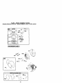
TILLER - - MODEL NUMBER 917.292480
DECALS
lO
KEY
NO,
PART
NO.
DESCRIPTION
2
4
5
6
7
8
9
10
11
12
--
166214
166215
137539
120431X
176783
120075X
167156
171078
162215
166217
176742
Decal, Logo
Decal, Belt Guard Tine Shield HP
Decal, Cntrl Phi lost,
Decal, Hand Placement
Decal, Engine Oper.
Decal, Warning, Rotating Tines
Decal, Engine B&S Intek
Decal, Rewind Intek
Decal, TIne Shielrl Warning
Decal Control Panel
Manual, Owner's (Eng,/Span)
,4t
TILLER - - MODEL f;u.i,_.i
_. ,. r..;,.,480
ENGINE, BRIGGS & STRATTON -- MODEL NUMBER 110402, TYPE NO. 0206-E1
307 _
24
,:
12 I
_
_
r_
Z
_li_....
22 -_
REQUIRESSPECIALTOOLS
TO INSTALL, SEE REPAIR
NSTRUCTON MANUAL.
_
718_
26 I
742'_
I_
_
32 _ 30 _,
;i:Iii!/_,/'i!
32A
1106eOWNER'S
MANUAL
I
7 ¸__I¸ ¸-
_;_' ' _._',_
42
TILLER - - MODEL NUMBER 917.292480
ENGINE, BRIGGS & STRATTON - MODEL NUMBER 110402, TYPE NO. 0206-E1
_,
'
!
_1_!
f
I
_i !
365
'
1633A
•
j
6331:!
6921
18d_
163
\
I
.... I
130'_ :
", _/
95 ''_
_: I 1171
276'_
276,_
I
__ 276'_"
51 /_"
137 _
, _
977 CARBURETOR._,_GASKET633
[_ISET
___633A
I
121 CARBURETOR OVERHAUL KIT
137i;
_;
104
127
6331:
633A _' |
;
358 ENGINE GASKET SET
i,
20
:
',
993
1022
"_
\
3
•
_
);
J
TILLER - - MODEL NUMBER 917.292480
ENGINE, BRIGGS & STRATTON -- MODEL NUMBER 110402,TYPE NO. 0206-E1
209
-_-_J 562
, i,
2221
427
505 '?' I
281
f
_"•
663
°,
773_,_
66271,
_
8'_
, _
'%_,
_
Im_l_._
'
209A
\
188_
. _ _,
j
_,
_/-
/
t
356 "
836A'_
621 _
832
300 y
613_
883 _ ;-_"
425
968
334 _'
971
163 7
44
_!
TILLER--MODELNUMBER
917.292480
ENGINE,
BRIGGS
&STRATTON
-- MODEL NUMBER 110402, TYPE NO. 0206-E1
!
_;
_
__S_
592_
,_
689 ,I_
456 i_
597
11036 EMISSIONS
LABEL
I
23
1005
48
1095 VALVE GASKET SET
45
TILLER-- MODELNUMBER
917.292480
ENGINE,
BRIGGS
&STRATTON
--MODEL
NUMBER
110402,
TYPENO.0206-E1
KEY
NO,
1
3
5
7
11
12
13
15
16
18
20
21
22
23
24
25
27
28
29
30
32
32A
33
34
35
36
40
45
PART
NO.
693811
299819
693643
695166
692600
692549
691137
691686
693797
694466
692550
281658
691662
692987
222698
690021
694167
694168
694169
499631
692786
692786
692787
691866
499423
499424
692562
691664
695759
499642
499641
691304
691304
692194
690977
48
46
693404
26
51
55
58
692555
691421
692259
60
65
95
97
98
281434
690837
691636
690024
398185
•
•+
•
•
•
DESCRIPTION
Cylinder Assembly
Seal-Oil (Magneto Side)
Head-Cylinder
Gasket-Cylinder Head
Tube-Breathar
Gasket-Crankcase
Screw (Cylinder Head)
Plug-Oil Drain
Crankshaft
Cover-Crankcase
Seal-Oil (PTO Side)
Cap-OilFill
Screw (Engine Surnp)
Flywheel
Key-Flywheel
Piston Assembly (Standard)
Piston Assembly .010" O.S.)
Piston Assembly (.020" O.S.)
Piston Assembly (.030" O.S.)
Ring Set-Piston (Standard)
Ring Set-Piston (.610" O.S.)
Ring Set-Piston (.020"O.S.)
Ring Set-Piston (.030" O.S.)
Lock-Piston Pin
Pin-Piston
Rod-Connectin._
D=pper-Connectmg Rod
Screw Connecting Rod)
Screw Connecting Rod)
Valve-Exhaust
Valve-Intake
Spring-Valve (Intake)
Spring-Valve (Exhaust)
Retainer-Valve
Tappet-Valve
Short
Block (Replacement
Camshaft
Engine)
Q:I:+ Gasket-Intake
Housing-Rewind Starter
Rope-Starter (Cut to
Required Length)
Gdp-Starter Rope
Screw (Rewind Starter)
Screw (Throttle Valve)
Shaft-Throttle
Kit-Idle Speed
KEY
NO.
104
108
109
117
121
122
125
127
130
133
134
137
146
155
161
163
186
187
188
189
190
209
209A
219
220
222
227
238
271
276
281
300
304
306
307
PART
NO.
DESCRIPTION
691242
O Pin-Float Hinge
692567
Valve-Choke
690023
Shaft-Choke
694975
Jet-Main (Standard)
695157
Kit-Carburetor Overhaul
693749 • _ Spacer-Carburetor
696065
Carburetor
691739
O Plug-Welch
691181
Valve-Throttle
398187
Float-Carburetor
398188
Q Kit-Needle/Seat
693981 Q:_ Gasket-Float Bowl
690979
Key-Timing
695882
Plate-Cylieder Head
696063
Base-Air Cleaner
696024
Gasket-Air Cleaner
692317
Connector-Hose
693401
Line-Fuel (Molded)
690877
Screw (Control Bracket)
694543
Ball-Rocker Arm
692127
Screw (Fuel Tank)
691278
Spring-Governor
692571
Spring-Governor
693578
Gear-Governor
691724
Washer (=GovernorGear)
694253
Bracket-control
692573
Control Lever-Governor
691300
Cap-Valve
694256
Lever-Control
271716 Q1: SaalingWasher
694252
Panel-Control
693593
Muffler
696066
Housin-g-Blower
693610
Shield-Cylinder
690345
Screw (Cylinder Shield)
•
High Speed:
Speed: 1900-2100
3000.3200
RPM Settings:Low
Included in Engine Gasket Set, Key. No.
358
Included in Carburetor Overhaul Kit, Key.
No. 121
Included in Carburetor Gasket Set, Key.
No. 977
included in Valve Gasket Set, Key. No.
1096
Q
_
+
NOTE:
46
All component dimensions given in U.S.
inches 1 inch = 25.4 turn
TILLER - - MODEL NUMBER 917.292480
ENGINE, BRIGGS & STRATTON - MODEL NUMBER 110402,TYPE NO. 0206-E1
KEY
NO.
332
333
334
337
356
358
363
365
383
415
425
427
445
455
456
459
504
505
552
562
592
597
801
808
613
615
618
619
621
632
PART
NO.
690662
692605
691061
491055
692390
695155
19069
692568
19374
693463
692583
694255
491588
692591
692299
281505
694254
891251
892345
891112
690800
591696
95162
497680
691666
692576
692547
891108
692310
893408
DESCRIPTION
Nut (Flywheel)
Armature-Magneto
Screw(Armature Magneto)
Spark Plug
Wire-Stop
Engine Gasket Set
Flywheel Puller
Screw (Carburetor)
Wrench-Spark Plug
Plug
Screw (Air Cleaner Cover)
Nut (Control Bracket)
Filter.Air Cleaner Cartridge
Cup-Flywheel
Plete-Paw! Friction
PawI-Ratchet
Washer Set
Nut (Governor Control Lever)
Bushing-Governor Crank
Bolt (Governor Control Lever)
Nut (Rewind Starter)
Screw (Pawl Friction Plate)
Clamp-Hose
Starter-Rewind
Screw (Muffler)
Retainer-Governor Shaft
Crank-Governor
Screw (Cylinder Head Plate)
Switch-Stop
Spdng/Link-Mechanical
Governor
633 893867 et Seal-Choke/Throttle
Shaft
633A 691321 Q:_ Seal-Throttle Shaft
635
692076
Boot-Sparkplug
663
694593
Screw (Control Panel)
668 694257
Spacer
676 393757
Deflector-Muffler
677 690661
Screw (Muffler Deflector)
689 691855
Bpring-Fdction
692 690572
Spring-Detent
718
690959
Ptn-Locating
741
692565
Gear-Timing
KEY
NO.
742
746
773
830
832
836
836A
851
868
883
914
914A
957
968
971
972
975
977
993
1005
1019
1022
1023
1026
1029
1034
1036
1058
1095
1182
1210
PART
NO.
692564
692566
694258
694544
693583
690661
693624
493880
692044
691893
692198
692557
694281
692584
690370
894280
493640
695156
691892
692592
694851
691890
499924
693517
691230
691343
695041
274263
695289
692590
498144
DESCRIPTION
Retainer-E Ring
Gear-Idler
Retainer
Stud(RockerArm)
Guard-Muffler
Screw (Muffler Guard)
Screw (Muffler Guard)
TerminaI-Sparkplug
*+ Seal-Valve
*+ Gasket-Exhaust
Screw (Rocker Cover)
Screw (RockerCover)
Cap-Fuel Tank
Cover-Air Cleaner
Screw (Air Cleaner Base)
Tank-Fuel
Bowl-Float
Set-Carburetor Gasket
,+ Gasket-Cylinder Head Plate
Fan-Flywheel
Kit-Label
.+ Gasket-Rocker Cover
Cover-Rocker
Rod-Push
Arm-Rocker
Guide-Push Rod
Label.Emissions
Owner's Manual
Set-Valve Gasket
Screw (Flywheel Fan)
Assembly-Pulley/Spring
(Pulley)
1211 498144
Assembly-Pulley/Spring
(Spring)
RPM Settings:Low Speed: 1900-2100
High Speed: 3000-3200
Included in Engine Gasket Set, Key. No,
388
Q
Included in Carburetor Overhaul Kit, Key.
No. 121
:_
Included in Carburetor Gasket Set, Key.
No. 977
+
Included in Valve Gasket Set, Key. No.
1095
NOTE:
47
All component dimensions given in U.S.
inches 1 inch = 25.4 mm
Get it fixed, at your home or ours!
For repair of major brand appliances in your own home...
no matter who made it, no matter who sold it!
1-800-4-MY-HOME
s. Ao_i_,,day
or night
(1-800-469-4663)
www.sears.com
To bring in products such as vacuums,
lawn equipment and electronics for repair, call for
the location of your nearest Sears Parts & Repair Center.
1-800-488-1222
Anytime, day or night
www.sears.com
For the replacement parts, accessories and owner's manuals
that you need to do-it-yourself, call Sears PartsDirectSM!
1-800-366-PART
(1`800-366-7278)
6 am-
11 p.m, CST,
7 days a weak
www.sears.condpar tsdirect
To purchase or inquire about a Sears Service Agreement:
1-800-827-6655
7 a.rn.- 5 p.m.CST,Mon.- Sat.
Para pedir serviciode reparaci6na domicilio,
y para ordenar piazas con entrega a domicilio:
1`888-SU-HOGAR
TM
(1-888-784-6427)
Au Canada pour service an fran(;ais:
1.877-LE-FOYER
s"
(1-877-533-6937)
SEARS ]
HomeCentral _
O Sears, Roebuck
176742
and CO
11.8.00 TF
® RegisteredTrademark I TMTrademark of Sears, RoebuCkand Co.
® Marca Registrada ! lu Marca de F_briCa de Sears, Roebuck and CO.
"]b'_'_ted in U.S.A.