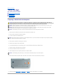
1
Dell™ Latitude™ D810 Service Manual
Before You Begin
System Components
Memory Modules, Mini PCI Card, Modem, and Modules
Internal Card With Bluetooth® Wireless Technology
The Coin-Cell Battery
Hard Drive
Center Control Cover
Display Assembly
Keyboard
Palm Rest
Smart Card Reader
PC Card Reader
Speakers
Microprocessor Thermal-Cooling Assembly
Microprocessor Module
Video Card Assembly
Fans
System Board
Flashing the BIOS
Pin Assignments for I/O Connectors
Notes, Notices, and Cautions
NOTE: A NOTE indicates important information that helps you make better use of your computer.
NOTICE: A NOTICE indicates either potential damage to hardware or loss of data and tells you how to avoid the problem.
CAUTION: A CAUTION indicates a potential for property damage, personal injury, or death.
Information in this document is subject to change without notice.
© 2005 Dell Inc. All rights reserved.
Reproduction in any manner whatsoever without the written permission of Dell Inc. is strictly forbidden.
Trademarks used in this text: Dell, the DELL logo, and Latitude are trademarks of Dell Inc.; Microsoft and Windows are registered trademarks of Microsoft Corporation; Bluetooth is a
trademark owned by Bluetooth SIG, Inc. and is used by Dell Inc. under license.
Other trademarks and trade names may be used in this document to refer to either the entities claiming the marks and names or their products. Dell Inc. disclaims any
proprietary interest in trademarks and trade names other than its own.
Model PP02X
February 2005 Rev. A00
Back to Contents Page
Back to Contents Page
Before You Begin
Dell™ Latitude™ D810 Service Manual
Preparing to Work Inside the Computer
Recommended Tools
Computer Orientation
Screw Identification
Preparing to Work Inside the Computer
CAUTION: Many repairs may only be done by a certified service technician. You should only perform troubleshooting and simple repairs as
authorized in Dell's product documentation, or as directed by Dell's online or telephone service and support team. Damage due to servicing that is
not authorized by Dell is not covered by your warranty. Read and follow the safety instructions that came with the product.
NOTICE: To prevent static damage to components inside your computer, discharge static electricity from your body before you touch any of your
computer's electronic components. You can do so by touching an unpainted metal surface.
NOTICE: Handle components and cards with care. Do not touch the components or contacts on a card. Hold a card by its edges or by its metal
mounting bracket. Hold a component such as a microprocessor by its edges, not by its pins.
NOTICE: To avoid damaging the computer, perform the following steps before you begin working inside the computer.
1.
Ensure that the work surface is flat and clean to prevent scratching the computer cover.
2.
Save any work in progress and exit all open programs.
3.
Turn off the computer and all attached devices.
NOTE: Ensure that the computer is off and not in a power management mode. If you cannot shut down the computer using the computer operating
system, press and hold the power button for 4 seconds.
4.
If the computer is connected to a docking device, undock it.
5.
Disconnect the computer from the electrical outlet.
6.
To avoid possible damage to the system board, wait 10 to 20 seconds and then disconnect any attached devices.
7.
Disconnect all other external cables from the computer.
8.
Remove any installed PC Cards from the PC Card slot.
9.
Close the display and turn the computer upside down on a flat work surface.
NOTICE: To avoid damaging the system board, you must remove the main battery before you service the computer.
10.
Slide and hold the battery-bay latch release on the bottom of the computer, and then remove the battery from the bay.
11.
Remove any installed memory modules, MiniPCI cards, and modules, including a second battery if one is installed.
Recommended Tools
The procedures in this manual require the following tools:
l
#1 Phillips screwdriver
l
¼-inch flat-blade screwdriver
l
Small plastic scribe
l
Flash BIOS update program floppy or CD
Computer Orientation
1
back
2
right
3
front
4
left
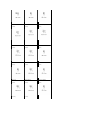
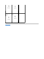
Screw Identification
When you are removing and replacing components, print this section as a tool to lay out and keep track of the screws. The placemat provides the number of
screws and their sizes.
Optional Module:
Modem:
Hard Drive:
(1 each)
(1 each)
(2 each)
Microprocessor Fan:
Keyboard:
Display Assembly:
(1 each)
(2 each)
(2 each)
Video Card Fan:
Display Latch:
Display Panel Cable:
(1 each)
(2 each)
(1 each)
Display Panel:
Speakers:
PC Card Reader
(8 each)
(1 each)
(4 each)
Palm Rest:
System Board:
Smart Card Reader
(4 each)
(3 each)
(1 each)
(13 each)
(1 each)
Internal card with
Bluetooth™ wireless
technology
(1 each)
Back to Contents Page
Button Board
(2 each)
Back to Contents Page
Flashing the BIOS
Dell™ Latitude™ D810 Service Manual
1.
Ensure that the AC adapter is plugged in and that the main battery is installed properly.
2.
Insert the flash BIOS update program floppy or CD and turn on the computer.
Follow the instructions that appear on the screen. The computer continues to boot and updates the new BIOS. When the update is complete, the
computer automatically reboots.
3.
Press <F2> during POST to enter the system setup program.
4.
Press <Esc>, select Save changes and reboot, and then press <Enter> to save configuration changes.
5.
Remove the flash BIOS update program floppy or CD from the drive and restart the computer.
Back to Contents Page
Back to Contents Page
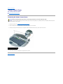
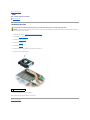
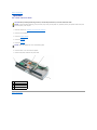
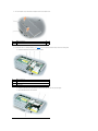
Internal Card With Bluetooth® Wireless Technology
Dell™ Latitude™ D810 Service Manual
CAUTION: Before performing the following procedures, read the safety instructions in your Product Information Guide.
NOTICE: To avoid electrostatic discharge, ground yourself by using a wrist grounding strap or by periodically touching an unpainted metal surface (such
as the back panel) on the computer.
If you ordered an internal card with Bluetooth® wireless technology with your computer, the card is already installed.
Removing the Card With Bluetooth Wireless Technology
1.
Follow the instructions in "Preparing to Work Inside the Computer."
2.
Remove the main battery.
3.
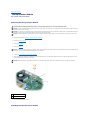
Locate the small access door in the battery compartment.
1
small access door
4.
Press the latch on the small access door and lift the door out.
5.
Remove the screw holding the Bluetooth wireless technology card.
6.
Grasp the card and disconnect it from the connector cable.
7.
Remove the card from the computer.
1
coin-cell battery
2
screw for card with Bluetooth wireless technology
3
card with Bluetooth wireless technology
Back to Contents Page
Back to Contents Page
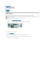
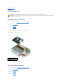
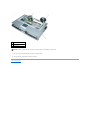
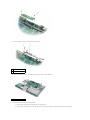
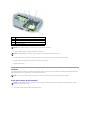
Center Control Cover
Dell™ Latitude™ D810 Service Manual
CAUTION: Before performing the following procedures, read the safety instructions in your Product Information Guide.
NOTICE: To avoid electrostatic discharge, ground yourself by using a wrist grounding strap or by periodically touching an unpainted metal surface (such
as the back panel) on the computer.
1
1.
Follow the instructions in "Preparing to Work Inside the Computer."
2.
Turn the computer top-side up and open it.
3.
Remove the center control cover:
a.
Open the display all the way (180 degrees) so that it lies flat against your work surface.
b.
Starting on the right side of the computer, use a plastic scribe or flat-blade screw driver to pry up the center control cover.
center control cover
c.
Lift the center control cover away from the computer, and lay it aside.
Back to Contents Page
Back to Contents Page
Coin-Cell Battery
Dell™ Latitude™ D810 Service Manual
CAUTION: Before you begin any of the procedures in this section, follow the safety instructions in your Product Information Guide.
A coin-cell battery maintains computer configuration, date, and time information. The battery can last several years.
The battery may need replacing if you have repeatedly reset the time and date information after turning on the computer or if a message appears that is
similar to one of the following:
Time-of-day not set - please run SETUP programs
or
Invalid configuration information -{
please run SETUP program
or
Strike the F1 key to continue, {
F2 to run the setup utility
To determine whether you need to replace the battery, reenter the time and date in system setup and exit the program to save the information. Turn off your
computer and disconnect it from the electrical outlet for a few hours; then reconnect the computer, turn it on, and enter system setup. If the date and time are
not correct in system setup, replace the battery.
You can operate your computer without a battery; however, without a battery, the configuration information is erased if the computer is turned off or
unplugged from the electrical outlet. In that case, you must enter system setup and reset the configuration options.
CAUTION: A new battery can explode if it is incorrectly installed. Replace the battery only with the same or equivalent type recommended by the
manufacturer. Discard used batteries according to the manufacturer's instructions.
To replace the battery:
1.
Record all the screens in the system setup program so that you can restore the correct settings in step 16.
2.
Shut down the computer through the Start menu.
3.
Ensure that your computer and attached devices are turned off. If your computer and attached devices did not automatically turn off when you shut
down your computer, turn them off now.
NOTICE: To disconnect a network cable, first unplug the cable from your computer, and then unplug it from the network wall jack.
4.
Turn off any attached devices and disconnect them from their electrical outlets.
5.
Disconnect the computer power cable from the wall outlet, and then press the power button to ground the system board.
CAUTION: To guard against electrical shock, always unplug your computer from the electrical outlet before opening the cover.
NOTICE: Before touching anything inside your computer, ground yourself by touching an unpainted metal surface, such as the metal at the back of the
computer. While you work, periodically touch an unpainted metal surface to dissipate any static electricity that could harm internal components.
6.
Turn the computer over and remove the main battery.
7.
Open the small access door in the main battery compartment.
8.
Locate the coin-cell battery next to the internal card with Bluetooth® wireless technology (optional).
9.
Use your fingers or a blunt, nonconducting object such as a plastic screwdriver to remove the battery by carefully prying it out of its socket .
10.
Disconnect the coin-cell battery connector.
11.
Insert the replacement battery into the socket and snap the battery into place.
12.
Connect the coin-cell battery connector to the replacement battery.
NOTICE: The connection to the replacement battery is keyed. Do not force the connection.
13.
Close the small access door.
14.
Insert the main battery and close the battery door.
NOTICE: To connect a network cable, first plug the cable into the network wall jack and then plug it into the computer.
15.
Connect your computer and devices to electrical outlets, and turn them on.
16.
Enter the system setup program and restore the settings you recorded in step 1.
17.
Properly dispose of the old battery. See the safety instructions in your Product Information Guide.
Back to Contents Page
Back to Contents Page
Microprocessor Module
Dell™ Latitude™ D810 Service Manual
Removing the Microprocessor Module
CAUTION: Before performing the following procedures, read the safety instructions in your Product Information Guide.
NOTICE: To avoid electrostatic discharge, ground yourself by using a wrist grounding strap or by periodically touching an unpainted metal surface (such
as the back panel) on the computer.
NOTICE: Do not touch the microprocessor die. Press and hold the microprocessor down on the substrate on which the die is mounted while turning the
cam screw to prevent intermittent contact between the cam screw and microprocessor.
NOTICE: To avoid damage to the microprocessor, hold the screwdriver so that it is perpendicular to the microprocessor when turning the cam screw.
1.
Follow the instructions in "Preparing to Work Inside the Computer."
2.
Remove the display assembly.
3.
Remove the keyboard.
4.
Remove the palm rest.
NOTICE: To ensure maximum cooling for the microprocessor, do not touch the heat transfer areas on the microprocessor thermal-cooling assembly. The
oils in your skin reduce the heat transfer capability of the thermal pads.
5.
Remove the microprocessor thermal-cooling assembly.
6.
Loosen the ZIF socket holding the microprocessor. To loosen the ZIF socket, use a small, flat- blade screwdriver and rotate the ZIF-socket cam screw
counterclockwise until it comes to the cam stop.
NOTICE: When removing the microprocessor module, pull the module straight up. Be careful not to bend the pins on the microprocessor module.
1
ZIF-socket cam screw
2
pin-1 corner
7.
Lift out the microprocessor module.
Installing the Microprocessor Module
NOTICE: Ensure that the cam lock is in the fully open position before seating the microprocessor module. Seating the microprocessor module properly in
the ZIF socket does not require force.
NOTICE: A microprocessor module that is not properly seated can result in an intermittent connection or permanent damage to the microprocessor and
ZIF socket.
1.
Align the pin-1 corner of the microprocessor module with the pin-1 corner of the ZIF socket, and insert the microprocessor module.
NOTE: The pin-1 corner of the microprocessor module has a triangle that aligns with the triangle on the pin-1 corner of the ZIF socket.
NOTICE: You must position the microprocessor module correctly in the ZIF socket to avoid permanent damage to the module and the socket.
When the microprocessor module is correctly seated, all four corners are aligned at the same height. If one or more corners of the module are higher
than the others, the module is not seated correctly.
2.
Tighten the ZIF socket by turning the cam screw clockwise to secure the microprocessor module to the system board.
3.
Perform the steps in "Removing the Microprocessor Module" in reverse order, beginning with step 5.
4.
Update the BIOS using a flash BIOS update program floppy or CD. For instructions on how to flash the BIOS, see "Flashing the BIOS."
Back to Contents Page
Back to Contents Page
Microprocessor Thermal-Cooling Assembly
Dell™ Latitude™ D810 Service Manual
Removing the Microprocessor Thermal-Cooling Assembly
CAUTION: Before performing the following procedures, read the safety instructions in your Product Information Guide.
NOTICE: To avoid electrostatic discharge, ground yourself by using a wrist grounding strap or by periodically touching an unpainted metal surface (such
as the back panel) on the computer.
NOTICE: Disconnect the computer and any attached devices from electrical outlets, and remove any installed batteries.
1.
Follow the instructions in "Preparing to Work Inside the Computer."
2.
Remove the display assembly.
3.
Remove the keyboard.
4.
Remove the palm rest.
5.
Loosen in consecutive order the four captive screws, labeled "1" through "4," that secure the microprocessor thermal-cooling assembly to the system
board.
1 captive screws (4)
2 microprocessor thermalcooling assembly
6.
Lift the microprocessor thermal-cooling assembly straight up and remove it from the system board.
Installing the Microprocessor Thermal-Cooling Assembly
1.
Place the microprocessor thermal-cooling assembly directly down onto the system board. Push straight down.
2.
Tighten the four captive screws, labeled "1" through "4," in consecutive order.
Back to Contents Page
Back to Contents Page
Center Control Cover
Dell™ Latitude™ D810 Service Manual
Removing the Center Control Cover
Removing the Center Control Cover
CAUTION: Before performing the following procedures, read the safety instructions in your Product Information Guide.
NOTICE: To avoid electrostatic discharge, ground yourself by using a wrist grounding strap or by periodically touching an unpainted metal surface (such
as the back panel) on the computer.
1.
Follow the instructions in "Preparing to Work Inside the Computer."
2.
Open the display all the way (180 degrees) so that it lies flat against your work surface.
3.
Starting on the right side of the computer, use a plastic scribe or flat-blade screw driver to pry up the center control cover.
1
center control cover
4.
Lift the center control cover away from the computer and lay it aside.
Back to Contents Page
Back to Contents Page
Display Assembly
Dell™ Latitude™ D810 Service Manual
Display Assembly
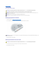
Display Bezel
Display Panel
Display Assembly
CAUTION: Before performing the following procedures, read the safety instructions in your Product Information Guide.
NOTICE: To avoid electrostatic discharge, ground yourself by using a wrist grounding strap or by periodically touching an unpainted metal surface (such
as the back panel) on the computer.
NOTICE: You must remove the display assembly before you remove the palm rest.
1.
Follow the instructions in "Preparing to Work Inside the Computer."
2.
Turn the computer over and remove the two M2.5 x 8-mm screws labeled "D" on the bottom of the computer.
3.
Turn over the computer and open the display.
4.
Remove the center control cover.
5.
Disconnect the display cable using the pull-tab, and release the cable from the cable-routing guides.
6.
Remove the antenna cable connector from its pocket on the computer base, and then gently disconnect the connector.
7.
Lift the display straight up out of the computer base.
1 display
2 pull-tab
3 display cable connector
4 antenna cable
5 computer base
6 system board connector
for display cable
Display Bezel
CAUTION: Before performing the following procedures, read the safety instructions in your Product Information Guide.
NOTICE: To avoid electrostatic discharge, ground yourself by using a wrist grounding strap or by periodically touching an unpainted metal surface (such
as the back panel) on the computer.
1.
Follow the instructions in "Preparing to Work Inside the Computer."
2.
Remove the display assembly.
3.
Use a plastic scribe to pry the six round display bumpers out of the screw holes located on the front of the bezel. Do not remove the oval bumpers.
4.
Remove the six M2.5 x 5-mm screws located on the front of the bezel under the bumpers.
NOTICE: Carefully separate the bezel from the top cover to avoid damage to the bezel.
5.
Separate the bezel from the top cover by lifting the inside edge of the bezel away from the top cover.
NOTE: You may need to use a plastic scribe to begin the separation.
Pull the bezel from the top edge toward the center of the panel to open the snaps. Push the bezel on the sides and bottom away from the center of the
panel to open the snaps.
NOTICE: To avoid damaging the bezel, start pulling the bezel up near the bottom of the display (near the Dell™ logo) and work around the display and
toward the release latch.
1 M2.5 x 5-mm screws (6) 4 display panel
2 display bumpers (6)
5 M2 x 3-mm screws (8)
3 display bezel
6 M2 x 3-mm display-cable ground screw
Display Panel
CAUTION: Before performing the following procedures, read the safety instructions in your Product Information Guide.
NOTICE: To avoid electrostatic discharge, ground yourself by using a wrist grounding strap or by touching an unpainted metal surface on the computer.
1.
Follow the instructions in "Preparing to Work Inside the Computer."
2.
Remove the center control cover.
3.
Remove the display assembly.
4.
Remove the display bezel.
Remove the eight M2 x 3-mm screws from sides of the display panel.
NOTE: The M2 x 3-mm screw located in the top left of the panel should be removed first and reinstalled first.
6.
Remove the M2 x 3-mm screw for the display cable ground, which is located at the bottom of the display panel.
7.
Lift the display panel straight up out of the top cover.
8.
Press in the tabs on both sides of the top display-cable connector, and pull the display cable connector away from the top flex-cable connector.
NOTE: Do not crimp or crunch cables during reinstallation.
1 top flex-cable connector
2 top display-cable
connector
3 tabs
9.
Use the pull-tab to disconnect the bottom flex-cable connector from the inverter display- cable connector.
1 inverter flex-cable
2 inverter display-cable
connector
3 pull-tab on bottom flexcable connector
Back to Contents Page
Back to Contents Page
Fan
Dell™ Latitude™ D810 Service Manual
Removing the Fan
Removing the Fan
CAUTION: Before performing the following procedures, read the safety instructions in your Product Information Guide.
NOTICE: To avoid electrostatic discharge, ground yourself by using a wrist grounding strap or by periodically touching an unpainted metal surface (such
as the back panel) on the computer.
1.
Follow the instructions in "Preparing to Work Inside the Computer."
2.
Remove the center control cover.
3.
Remove the display assembly.
4.
Remove the keyboard.
5.
Remove the palm rest.
6.
Remove the M2.5 x 5-mm screw from the top left corner of the fan.
7.
Disconnect the fan cable connector.
1
M2.5 x 5-mm screw
8.
Lift the fan straight up out of the computer.
When replacing the fan, follow the steps in reverse order.
Back to Contents Page
Back to Contents Page
Fans
Dell™ Latitude™ D810 Service Manual
CAUTION: Before performing the following procedures, read the safety instructions in your Product Information Guide.
NOTICE: To avoid electrostatic discharge, ground yourself by using a wrist grounding strap or by periodically touching an unpainted metal surface (such
as the back panel) on the computer.
Removing the Microprocessor Fan
1.
Follow the instructions in "Preparing to Work Inside the Computer."
2.
Remove the display assembly.
3.
Remove the keyboard.
4.
Remove the palm rest.
5.
Remove the M2.5 x 5-mm screw from the top left corner of the fan.
6.
Disconnect the fan cable connector.
1
M2.5 x 5-mm screw
2
fan cable connector
7.
Lift the fan straight up out of the computer.
Removing the Video Card Fan
1.
Follow the instructions in "Preparing to Work Inside the Computer."
2.
Remove the display assembly.
3.
Remove the keyboard.
4.
Remove the palm rest.
5.
Remove the M2.5 x 5-mm screw from the bottom right corner of the fan.
6.
Disconnect the fan cable connector.
7.
Lift the fan straight out of the computer.
1
M2.5 x 5-mm screw
2
fan cable connector
Back to Contents Page
Back to Contents Page
Hard Drive
Dell™ Latitude™ D810 Service Manual
CAUTION: If you remove the hard drive from the computer when the drive is hot, do not touch the metal housing of the hard drive.
CAUTION: Before working inside your computer, read the safety instructions in your Product Information Guide.
NOTICE: To prevent data loss, shut down your computer before removing the hard drive. Do not remove the hard drive while the computer is on, in
standby mode, or in hibernate mode.
NOTICE: Hard drives are extremely fragile; even a slight bump can damage the drive.
NOTE: Dell does not guarantee compatibility or provide support for hard drives from sources other than Dell.
Removing the Hard Drive and Carrier
1.
Follow the instructions in "Preparing to Work Inside the Computer."
2.
Turn the computer over. Use a standard #1 Phillips screwdriver to remove the two M3 x 3- mm screws.
NOTICE: When the hard drive is not in the computer, store it in protective antistatic packaging. See "Protecting Against Electrostatic Discharge" in your
Product Information Guide.
3.
Slide the hard drive out of the computer.
Removing the Hard Drive From the Carrier
CAUTION: If you remove the hard drive from the computer when the drive is hot, do not touch the metal housing of the hard drive.
1.
Use spring tension to gently pry the carrier open near the connector at the back of the carrier.
2.
Lift the hard drive out of the carrier.
Back to Contents Page
Back to Contents Page
Keyboard
Dell™ Latitude™ D810 Service Manual
CAUTION: Before performing the following procedures, read the safety instructions in your Product Information Guide.
NOTICE: To avoid electrostatic discharge, ground yourself by using a wrist grounding strap or by periodically touching an unpainted metal surface (such
as the back panel) on the computer.
1.
Follow the instructions in "Preparing to Work Inside the Computer."
2.
Turn the computer top-side up and open it.
1
display
2
center control cover
3
computer base
3.
Remove the center control cover.
4.
Remove the keyboard:
a.
Remove the two M2.5 x 5-mm screws across the top of the keyboard.
NOTICE: The keycaps on the keyboard are fragile, easily dislodged, and time-consuming to replace. Be careful when removing and handling the
keyboard.
b.
Lift the keyboard and slide it toward the back of the computer to disengage the tabs.
c.
Hold the keyboard up at an angle and slightly back to allow access to the keyboard connector.
d.
Pull up on the keyboard connector tab to disconnect the keyboard connector from the system board.
1
M2.5 x 5-mm screws (2)
2
keyboard
3
palm rest
4
keyboard tabs (5)
Back to Contents Page
Back to Contents Page
Palm Rest
Dell™ Latitude™ D810 Service Manual
CAUTION: Before performing the following procedures, read the safety instructions in your Product Information Guide.
NOTICE: To avoid electrostatic discharge, ground yourself by using a wrist grounding strap or by periodically touching an unpainted metal surface (such
as the back panel) on the computer.
1.
Follow the instructions in "Preparing to Work Inside the Computer."
2.
Remove the display assembly.
NOTICE: You must remove the display assembly before you remove the palm rest; the display hinges pass through the back of the palm rest.
3.
Remove the keyboard.
4.
Remove the 13 M2.5 x 8-mm screws from the bottom of the computer.
1
M2.5 x 5-mm screws (4)
2
top of the palm rest
5.
Remove the four M2.5 x 5-mm screws labeled "P" from the top of the palm rest.
6.
Disconnect the system board connector from the system board.
7.
Disconnect the touch pad connector from the system board.
1
touch pad connector
2
system board connector
3
computer base
NOTICE: Carefully separate the palm rest from the computer base to avoid damage to the palm rest.
8.
Use your fingers to separate the palm rest from the computer base.
9.
Lift the palm rest, pulling apart the snaps on the base.
Back to Contents Page
Back to Contents Page
PC Card Reader
Dell™ Latitude™ D810 Service Manual
CAUTION: Before performing the following procedures, read the safety instructions in your Product Information Guide.
NOTICE: To avoid electrostatic discharge, ground yourself by using a wrist grounding strap or by periodically touching an unpainted metal surface (such
as the back panel) on the computer.
Removing the PC Card Reader
1.
Follow the instructions in "Preparing to Work Inside the Computer."
2.
Remove the display assembly.
3.
Remove the keyboard.
4.
Remove the palm rest.
5.
Remove the four M2 x 3-mm screws securing the PC card reader to the system board.
6.
Use the pull-tab to disconnect the PC Card reader connector from the system board.
1
PC Card reader
2
M2 x 3-mm screws (4)
3
connector pull-tab
7.
Lift the PC card reader straight up out of the computer.
Back to Contents Page
Back to Contents Page
Pin Assignments for I/O Connectors
Dell™ Latitude™ D810 Service Manual
USB Connector
Video Connector
S-Video TV-Out Connector
Serial Connector
USB Connector
Pin Signal
1
USB5V+
2
USBP–
3
USBP+
4
GND
Video Connector
Pin Signal Pin Signal
1
CRT_R 9
5V+
2
CRT_G 10
GND
3
CRT_B 11
MONITOR_DETECT–
4
NC
12
DDC_DATA
5
GND
13
CRT_HS
6
GND
14
CRT_VS
7
GND
15
DDC_CLK
8
GND
S-Video TV-Out Connector
S-Video
Pin Signal
1
GND
2
GND
3
DLUMA-L
4
DCRMA-L
Composite Video
Pin
Signal
5
SP_DIF
6
DCMPS-L
7
SP_DIF
Serial Connector
Pin Signal Pin Signal
1
DCD
6
DSR
2
RXDA
7
RTS
3
TXDA
8
CTS
4
DTR
9
RI
5
GND
Back to Contents Page
Back to Contents Page
Smart Card Reader
Dell™ Latitude™ D810 Service Manual
CAUTION: Before performing the following procedures, read the safety instructions in your Product Information Guide.
NOTICE: To avoid electrostatic discharge, ground yourself by using a wrist grounding strap or by periodically touching an unpainted metal surface (such
as the back panel) on the computer.
Removing the Smart Card Reader
1.
Follow the instructions in "Preparing to Work Inside the Computer."
2.
Remove the display assembly.
3.
Remove the keyboard.
4.
Remove the palm rest.
5.
Locate the smart card reader and disconnect the smart-card ZIF connector from the system board.
1 smart card reader
2 M2 x 3-mm screw
3 smart-card ZIF connector
6.
Remove the single M2 x 3-mm screw in the neck of the smart card reader.
7.
Lift the smart card reader slightly and slide it out from under the tabs holding it in place.
Back to Contents Page
Back to Contents Page
Smart Card Reader
Dell™ Latitude™ D810 Service Manual
Removing the Smart Card Reader
Removing the Smart Card Reader
CAUTION: Before performing the following procedures, read the safety instructions in your Product Information Guide.
NOTICE: To avoid electrostatic discharge, ground yourself by using a wrist grounding strap or by periodically touching an unpainted metal surface (such
as the back panel) on the computer.
1.
Follow the instructions in "Preparing to Work Inside the Computer."
2.
Remove the center control cover.
3.
Remove the display assembly.
4.
Remove the keyboard.
5.
Remove the palm rest.
6.
Locate the smart card reader and disconnect the smart card ZIF connector from the system board.
1
smart card reader
2
M2 x 3-mm screw
3
ZIF connector
7.
Remove the single M2 x 3-mm screw in the neck of the smart card reader.
8.
Lift the smart card reader slightly and slide it out from under the tabs holding it in place.
When replacing the smart card reader, follow the steps in reverse order.
Back to Contents Page
Back to Contents Page
Speakers
Dell™ Latitude™ D810 Service Manual
CAUTION: Before performing the following procedures, read the safety instructions in your Product Information Guide.
NOTICE: To avoid electrostatic discharge, ground yourself by using a wrist grounding strap or by periodically touching an unpainted metal surface (such
as the back panel) on the computer.
1.
Follow the instructions in "Preparing to Work Inside the Computer."
2.
Remove the coin-cell battery.
3.
Remove the display assembly.
4.
Remove the keyboard.
5.
Remove the palm rest.
NOTICE: Handle the speakers with care to avoid damaging them.
6.
Remove the M2.5 x 5-mm screw from the speakers.
7.
Disconnect the speaker cable from the system board.
1
speakers
2
M2.5 x 5-mm screw
3
speaker cable connector
4
computer base
Back to Contents Page
Back to Contents Page
System Board
Dell™ Latitude™ D810 Service Manual
Removing the System Board
CAUTION: Before performing the following procedures, read the safety instructions in your Product Information Guide.
NOTICE: To avoid electrostatic discharge, ground yourself by using a wrist grounding strap or by periodically touching an unpainted metal surface (such
as the back panel) on the computer.
The system board's BIOS chip contains the Service Tag, which is also visible on a barcode label on the bottom of the computer. The replacement kit for the
system board includes a CD that provides a utility for transferring the Service Tag to the replacement system board.
NOTICE: Disconnect the computer and any attached devices from electrical outlets, and remove any installed batteries.
1.
Follow the instructions in "Preparing to Work Inside the Computer."
2.
Remove any installed modules.
3.
Remove the mini PCI card.
4.
Remove the modem.
5.
Remove the display assembly.
6.
Remove the keyboard.
7.
Remove the palm rest.
8.
Remove the video-card thermal cooling assembly.
9.
Remove the microprocessor thermal-cooling assembly.
10.
Remove the video card fan.
11.
Remove the microprocessor fan.
12.
Remove the memory.
13.
Remove the microprocessor.
14.
Remove the hard drive.
15.
Remove the smart card reader.
16.
Remove the PC Card carrier.
17.
Remove the speakers.
18.
Remove the two M2.5 x 5-mm screws from the button board.
19.
Remove the M2 x 3-mm screw from the system board support.
1
M2 x 3-mm screw
2
system board support
20.
1
Remove the three M2.5 x 5-mm screws that secure the system board to the computer base.
M2.5 x 5-mm screws (3)
21.
Remove the system board from the computer base.
a.
Ensure that you have disconnected all cables from the system board.
b.
Gently lift the board starting from the left side, and then pull to the left to dislodge the audio connectors from the holes in the base.
NOTE: You may need to press outward on the base near the audio connectors to provide enough clearance for the audio connectors.
c.
After the connectors are dislodged, lift the board out of the base.
Installing the System Board
1.
Perform all the steps in "Removing the System Board" in reverse order.
NOTICE: Before turning on the computer, replace all screws and ensure that no stray screws remain inside the computer. Failure to do so may result in
damage to the computer.
2.
Turn on the computer.
NOTE: After replacing the system board, enter the computer Service Tag into the BIOS of the replacement system board.
3.
Insert the floppy or CD that accompanied the replacement system board into the appropriate drive. Follow the instructions that appear on the screen.
Back to Contents Page
Back to Contents Page
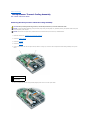
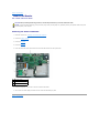
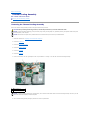
System Components
Dell™ Latitude™ D810 Service Manual
NOTICE: Only a certified service technician should perform repairs on your computer. Damage due to servicing that is not authorized by Dell is not
covered by your warranty.
NOTICE: Unless otherwise noted, each procedure in this document assumes that a part can be replaced or, if purchased separately, installed by
performing the removal procedure in reverse order.
1
display assembly
11 optical drive
2
display cable
12 battery
3
center control cover
13 computer base
4
keyboard
14 speakers
5
palm rest
15 hard drive
6
video-card assembly
16 PCMIA card slot
7
video-card assembly fan 17 smart card reader
8
button board
18 microprocessor
9
system board support
19 microprocessor fan
10 system board
Back to Contents Page
20 microprocessor thermal-cooling assembly
Back to Contents Page
Thermal-Cooling Assembly
Dell™ Latitude™ D810 Service Manual
Removing the Thermal-Cooling Assembly
Removing the Thermal-Cooling Assembly
There is one thermal-cooling assembly for both the integrated video and the processor.
CAUTION: Before performing the following procedures, read the safety instructions in your Product Information Guide.
NOTICE: To avoid electrostatic discharge, ground yourself by using a wrist grounding strap or by periodically touching an unpainted metal surface (such
as the back panel) on the computer.
NOTICE: Disconnect the computer and any attached devices from electrical outlets, and remove any installed batteries.
1.
Follow the instructions in "Preparing to Work Inside the Computer."
2.
Remove the hard drive.
3.
Remove the center control cover.
4.
Remove the display assembly.
5.
Remove the keyboard.
6.
Remove the palm rest.
7.
Loosen in consecutive order the eight captive screws. They are labeled "1" through "4" on each side of the thermal-cooling assembly.
1 captive screws (8)
2 thermal-cooling assembly
NOTICE: To ensure maximum cooling for the microprocessor, do not touch the heat transfer areas on the thermal-cooling assembly. The oils in your skin
reduce the heat transfer capability of the thermal pads.
8.
Lift the thermal-cooling assembly straight up and remove it from the system board.
When replacing the thermal-cooling assembly, follow the steps in reverse order.
Back to Contents Page
Back to Contents Page
Dell™ Latitude™ D810 Service Manual
Notes, Notices, and Cautions
NOTE: A NOTE indicates important information that helps you make better use of your computer.
NOTICE: A NOTICE indicates either potential damage to hardware or loss of data and tells you how to avoid the problem.
CAUTION: A CAUTION indicates a potential for property damage, personal injury, or death.
Information in this document is subject to change without notice.
© 2005 Dell Inc. All rights reserved.
Reproduction in any manner whatsoever without the written permission of Dell Inc. is strictly forbidden.
Trademarks used in this text: Dell, the DELL logo, and Dell Precision are trademarks of Dell Inc.; Microsoft and Windows are registered trademarks of Microsoft Corporation;
Bluetooth is a trademark owned by Bluetooth SIG, Inc. and is used by Dell Inc. under license.
Other trademarks and trade names may be used in this document to refer to either the entities claiming the marks and names or their products. Dell Inc. disclaims any
proprietary interest in trademarks and trade names other than its own.
Model PP02X
February 2005 Rev. A00
Back to Contents Page
Back to Contents Page
Memory Modules, Mini PCI Card, Modem, and Devices
Dell™ Latitude™ D810 Service Manual
Memory Modules
Mini PCI Card
Modem
Devices
Memory Modules
The computer has two memory slots, DIMM A and DIMM B. DIMM A (under the keyboard) holds the basic memory module as configured from the factory. If you
did not order additional memory, DIMM B (on the bottom of the computer) is empty. If you are adding memory, you will install a memory module in DIMM B (on
the bottom of the computer under the options cover). If you are upgrading memory, you may need to install memory in DIMM A and DIMM B.
Memory Module DIMM B
CAUTION: Before working inside your Dell™ computer, read the safety instructions in your Product Information Guide.
NOTICE: To prevent static damage to components inside your computer, discharge static electricity from your body before you touch any of your
computer's electronic components. You can do so by touching an unpainted metal surface.
NOTE: Memory modules purchased from Dell are covered under your computer warranty.
1.
Follow the instructions in "Preparing to Work Inside the Computer."
2.
Turn the computer over, loosen the two captive screws from the options cover (bottom door), and lift the cover.
1
captive screws (2)
2
options cover
NOTICE: To prevent damage to the memory module connector, do not use tools to spread the inner metal tabs that secure the memory module.
3.
If you are replacing a memory module, remove the existing module.
NOTICE: Handle memory modules by their edges, and do not touch the components on a module.
a.
Use your fingertips to carefully spread apart the securing clips on each end of the memory module connector until the module pops up.
b.
Remove the module from the connector.
1
securing clips (2 per connector)
2
memory module
4.
Ground yourself and install the new memory module:
a.
b.
Align the notch in the module with the slot in the center of the connector.
Slide the edge of the module firmly into the connector, and rotate the module down until you feel a click. If you do not feel the click, remove the
module and reinstall it.
NOTE: If the memory module is not installed properly, the computer does not boot. The Num Lock and Scroll Lock lights blink about 10 times.
5.
Replace the cover and screws.
NOTICE: If the memory module cover is difficult to close, remove the module and reinstall it. Forcing the cover to close may damage your computer.
6.
Insert the battery into the battery bay, or connect the AC adapter to your computer and an electrical outlet.
7.
Turn on the computer.
DIMM A Memory Module
CAUTION: Before working inside your Dell™ computer, read the safety instructions in your Product Information Guide.
NOTICE: To prevent static damage to components inside your computer, discharge static electricity from your body before you touch any of your
computer's electronic components. You can do so by touching an unpainted metal surface.
NOTE: Memory modules purchased from Dell are covered under your computer warranty.
1.
Follow the instructions in "Preparing to Work Inside the Computer."
2.
Remove the center control cover.
3.
Remove the keyboard. The memory module DIMM A is located under the keyboard.
NOTICE: To prevent damage to the memory module connector, do not use tools to spread the inner metal tabs that secure the memory module.
4.
If you are replacing a memory module, remove the existing module.
NOTICE: Handle memory modules by their edges, and do not touch the components on a module.
a.
Use your fingertips to carefully spread apart the securing clips on each end of the memory module connector until the module pops up.
b.
Remove the module from the connector.
1
securing clips (2 per connector)
2
memory module
5.
Ground yourself and install the new memory module:
a.
b.
Align the notch in the module with the slot in the center of the connector.
Slide the edge of the module firmly into the connector, and rotate the module down until you feel a click. If you do not feel the click, remove the
module and reinstall it.
NOTE: If the memory module is not installed properly, the computer does not boot. The Num Lock and Scroll Lock lights blink about 10 times.
6.
Replace the keyboard and center control cover.
7.
Insert the battery into the battery bay, or connect the AC adapter to your computer and an electrical outlet.
8.
Turn on the computer.
When You Have Installed the Memory Module(s)
If You Are Replacing Memory
As the computer boots, it detects the installed memory. The system configuration information remains the same.
If You Are Adding or Upgrading Memory
As the computer boots, it detects the change in memory and automatically updates the system configuration information.
Confirming Installed Memory
To confirm the amount of memory installed in the computer, use one of the following methods:
l
l
Click the Start button, click Help and Support, and then click Computer Information.
Access the System Setup Program by pressing <F2> immediately when the DELL™ logo appears. If you wait too long and the Windows logo appears,
continue to wait until you see the Windows desktop. Then shut down your computer and try again. See "Using the System Setup Program" in your
User's Guide.
Mini PCI Card
If you ordered a Mini PCI card at the same time that you ordered your computer, Dell has already installed the card for you.
CAUTION: Before working inside your computer, read the safety instructions in your Product Information Guide.
NOTICE: To prevent static damage to components inside your computer, discharge static electricity from your body before you touch any of your
computer's electronic components. You can do so by touching an unpainted metal surface.
NOTICE: Handle components and cards by their edges, and avoid touching pins and contacts.
1.
Follow the instructions in "Preparing to Work Inside the Computer."
2.
Turn the computer over, and loosen the captive screws on the options cover.
1
captive screws (2)
2
options cover
3.
If a Mini PCI card is not already installed, go to step 4. If you are replacing a Mini PCI card, remove the existing card:
a.
Disconnect the Mini PCI card from any attached cables.
1
antenna cables (2)
2
metal securing tabs
3
Mini PCI card connector
4
Mini PCI card
b.
Release the Mini PCI card by spreading the metal securing tabs until the card pops up slightly.
c.
Lift the Mini PCI card out of its connector.
1
Mini PCI card connector
2
Mini PCI card
3
antenna cables (2)
NOTICE: To avoid damaging the Mini PCI card, never place cables on top of or under the card.
NOTICE: The connectors are keyed to ensure correct insertion. If you feel resistance, check the connectors and realign the card.
4.
To install the Mini PCI card, align the Mini PCI card with the connector at a 45-degree angle, and press the Mini PCI card firmly into the connector. Press
down until you feel a click.
NOTE: If the Mini PCI card's antenna cables have insulation tubes over the connectors, remove the tubes.
5.
Connect the antenna cables to the Mini PCI card.
6.
Replace the cover and tighten the screw.
Modem
CAUTION: Before working inside your computer, read the safety instructions in your Product Information Guide.
CAUTION: To prevent static damage to components inside your computer, discharge static electricity from your body before you touch any of
your computer's electronic components. You can do so by touching an unpainted metal surface.
NOTICE: Handle components and cards by their edges, and avoid touching pins and contacts.
1.
Follow the instructions in "Preparing to Work Inside the Computer."
2.
Turn the computer over, and loosen the captive screws from the options cover.
1
captive screws (2)
2
options cover
3.
If a modem is not already installed, go to step 4. If you are replacing a modem, remove the existing modem:
a.
Remove the M2 x 3-mm screw securing the modem to the system board, and set it aside.
b.
Pull straight up on the attached pull-tab to lift the modem out of its connector on the system board, and disconnect the modem cable.
1
modem cable
2
modem
3
pull-tab
4
screw
5
system board connector
NOTICE: Cable connectors are keyed for correct insertion; do not force the connections.
4.
If you are installing a modem, connect the modem cable to the modem.
NOTICE: To prevent damage to the modem, press the modem into the connector directly over the connector.
5.
Align the modem with the screw hole, and press the modem into the connector directly over the connector on the system board.
6.
Replace the M2 x 3mm modem screw and secure the modem to the system board.
7.
Replace the options cover.
Devices
Your computer ships with an optical drive installed in the module bay. However, the device screw is not installed in the optical drive but packaged separately.
When you install your device in the module bay, you can install the device screw.
NOTE: You do not need to install the device screw unless you want to secure the device inside the computer for security purposes.
If the Device Screw Is Not Installed
NOTICE: To prevent damage to devices, place them in a safe, dry place when they are not installed in the computer. Avoid pressing down on them or
placing heavy objects on top of them.
1.
Press the device latch release so that the latch release pops out.
1
device latch release
2.
Pull the device by the latch release to remove the device from the module bay.
If the Device Screw Is Installed
1.
If the computer is connected to a docking device (docked), undock it. See the documentation that came with your docking device for instructions.
NOTICE: To prevent damage to devices, place them in a safe, dry place when they are not installed in the computer. Avoid pressing down on them or
placing heavy objects on top of them.
2.
Close the display and turn the computer over.
3.
Use a #1 Phillips screwdriver to remove the M2 x 3-mm screw from the bottom of the computer.
1
device latch release
4.
Press the device latch release so that the latch release pops out.
5.
Pull the device by the latch release to remove the device from the module bay.
NOTICE: Insert devices into the module bay before you dock and turn on the computer.
Back to Contents Page
Back to Contents Page
Video Card Assembly
Dell™ Latitude™ D810 Service Manual
Removing the Video Card Assembly
CAUTION: Before performing the following procedures, read the safety instructions in your Product Information Guide.
NOTICE: To avoid electrostatic discharge, ground yourself by using a wrist grounding strap or by periodically touching an unpainted metal surface (such
as the back panel) on the computer.
NOTICE: Disconnect the computer and any attached devices from electrical outlets, and remove any installed batteries.
1.
Follow the instructions in "Preparing to Work Inside the Computer."
2.
Remove the display assembly.
3.
Remove the keyboard.
4.
Remove the palm rest.
5.
Loosen the four M2.5 corner screws (marked with a triangle on the thermal-cooling assembly) from the video card assembly. These screws connect the
video-card thermal-cooling assembly to the system board.
1 M2.5 x 5-mm corner
screws
2 video card assembly
6.
Lift the video card assembly straight up and out of the computer.
Back to Contents Page