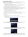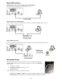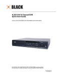
1
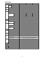
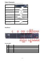
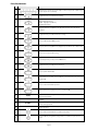
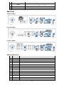
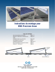
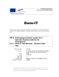
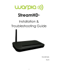
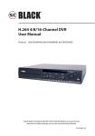
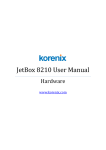
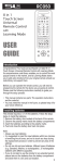
® H.264 4/8/16 Channel DVR Quick Start Guide Products: BLK-DH200400D, BLK-DH200800D, BLK-DH201600D PLEASE READ THIS GUIDE BEFORE USING YOUR RECORDER, and always follow the instructions for safety and proper use. Save this guide for future reference. BLK-D20xx00D_RQ 3/2/11 © 2011 Supercircuits, Inc. Specifications* ITEM Input Video Audio Alarm Output BLK-DH200400D BLK-DH200800D Channel, Input Level 4/8/16 channel composite video, 1.0 Vp-p, 75Ω Main Monitor Output 1 VGA (1280 x 1024 @ 60Hz), Spot 2 (Event, Live) Input & Output 4 CH line input & 1 CH line output Audio CODEC G.711 (ADPCM) Sensor Input 4ch (NC/NO selectable) Alarm Output 1 Alarm out by Sensor, Motion and Video Loss Compression H.264 Multi-operation Record Resolution QUADPLEX (Playback/Record/Network/Backup) D1 120 fps 120 fps 120 fps Half D1 120 fps 240 fps 240 fps CIF 120 fps 240 fps 480 fps Recording quality grade NETWORK, STANDARD, HIGH, SUPERIOR, ULTRA Recording Mode Continuous / Schedule / Motion/ Sensor/ Manual Pre & Post Recording Display Yes Frame rate ( /Sec) 30 fps/channel, 60 fields Multi-Decoding Playback Playback speed HDD Storage Serial port 1, 4, 8, 16 Single channel × 2, 4, 8, 16 Multi-channels × 2, 4 Capacity of 1 HDD 2TB Internal HDD 1 E-SATA Port 1 USB Port Backup User I/F 2 (1 front, 1 rear) USB flash drive Video and still image Network Input method Video and still image Front button, remote control, mouse, keyboard controller Console 1 RS-232C PTZ and DVR keyboard control 1 RS-485 Termination Network Network Access Yes Dynamic DNS Yes (free DDNS) Dual encoding for network streaming CIF 120 fps/100 fps Web viewer (1:1) Live, Search, Backup, PTZF Cam Control, Remote Setup Single site monitoring system: UMS Single Client (1:1) Live, Search, Backup, PTZF Cam Control, Remote Setup Multi-sites monitoring system: UMS Multi Client (1:n) Live, Search, Backup, PTZF Cam Control, Remote Setup DLS (Day Light Saving) & NTP Features Yes Internal Beep By Alarm, Motion, Video Loss, HDD error Multi-Language Yes (more than 13 languages) 3G mobile smartphone viewer Power BLK-DH201600D Yes Power Supply Voltage DC 12V 5A Operating temperature 41°F – 104°F (5°C – 40°C) Storage temperature Weight Unit Weight / Gross weight Dimension WxHxD 14°F – 122°F (-10°C – +50°C) 9.04 lbs. / 13.67 lbs. (4.1Kgs / 6.2Kgs) 15.0” x 13.4” x 2.83” (380mm x 340mm x 72mm) DVD RW drive disk compatibility CD-R/W, DVD-R/W * Specifications and exterior design are subject to change without notice. Page 2 Prroduct C Compone ents The e package conttains the DVR unit u and the components sho own below. DVR unit So oftware CD (with h user manual) / Quick Q Start Guide / HDD mounting sccrews ( 4 screws) Ad daptor (DC 12V 5A) 5 and power caable Mouse M Re emote control an nd batteries / HDD mounting brracket and Screw ws (1 et) se HDD Data Power Cable C (1) Frront Panel Front Panel L LEDs NO. Na ame Description A H1~16 CH Indicates thaat the channel is being recorded. B HDD Indicates thaat the system is accessing the hard disk. C ALARM Indicates thaat sensor(s) is/are e triggered or mo otion is detected. D NETWORK Indicates thaat a network clien nt is connected E ACKUP BA Indicates thaat a USB or DVD-R RW device contains stored data F OWER PO Indicating th hat the system is switched on. Page 3 Front Panel B Buttons No. Nam me Description 1 ey. For channel 11 1, press the +10 aand 1 key. For Channel keys. For channel 10, press the 0 ke channel 16,, press the +10 and 6 key. 2 In playbackk mode, press to rrewind the recorrding. 3 Press to sele ect an audio mod de: MUTE – Mu ute all 4 channels. SINGLE - Highlighted chann nel only. MIX - Mix alll 4 channels. 4 Jump/step backward. In plaayback mode, the e playback position moves 60 secconds backward. 5 In playbackk mode, press to ffast forward the recording. 6 Press to enaable/disable ALA ARM operation. 7 Jump/step forward. In playb back mode, the playback p position n moves 60 secon nds forward. 8 Press to start or stop manuaal recording. 9 In live display mode, press to t open the SEAR RCH menu. 10 In playbackk mode, press to p play/pause the fo ootage. 11 Press to ope en the SETUP me enu. 12 Enable/disaable the automattic sequence of display d of channe els in full screen, quad, 9-split display mod de. 13 Press to con ntrol Pan/Tilt/Zoo om operations. 14 Press to cap pture video in jpe eg format in live or playback mod de. 15 (LE EFT) Press to mo ove left or to chan nge the values in n Setup mode. It is also used as th he number 4 when enterring password. 16 (U UP) Press to mo ove up the menu in Setup mode. It is also used as the number 1 when w entering password. 17 (RIG GHT) Press to mo ove right or to change the values in Setup mode. It I is also used as the t number 2 when entering password. 18 (DO OWN) Press to mo ove down the me enu in Setup mod de. It is also used d as the number 3 when entering paassword. 19 Press to sele ect desired menu u item or to store e the setup value e. 20 Press for tem mporary storage e of the changed value or to returrn to the previous menu screen. Page 4 No. Nam me Description 21 USB port p 22 OPEN/C CLOSE Press to ope en or close the disk tray. 23 DVD drive d To save vide eo, insert a CD-R//DVD-R To save a sn napshot image or video clip on a USB flash drive, or o upgrade firmw ware with a USB flash drive, first connecct the USB flash drive d to the USB port. p Re ear Pane el BLK-DH200400D D DVR BLK-DH200800D D DVR BLK-DH201600D D DVR Re ear Panel C Connectorss No. Label Definition 1 VID DEO IN Video input terminals 2 CV VBS OUT Spot out term minal. Spot out 1:: Live view screen n. Spot out 2: On ne channel screen n with an event image. 3 AU UDIO IN Four connecttors for audio inp put. 4 AU UDIO OUT One connector for audio outp put. 5 VG GA VGA (Video Graphics G Array) output terminal. Connects C to the PC P VGA monitor. 6 RS S-232C For engineeriing use only. 7 ET THERNET Network term minal 8 SE ENSOR IN 4 connectors for sensor devicce connection. 9 AL LARM OUT 1 connector for f alarm device connection. Provvides simple On//Off switching byy using relay. (A, B) B 10 RS S-485 RS-485 contro ol terminal. (D+, D-) 11 PO OWER DC12V 12 US SB USB port 13 SA ATA External SATA A port 14 Co ooling fan Page 5 Sy ystem Installation and Se etup The following ssteps include the general procedure for installing an nd setting up p your system m. For specificc instructions on ps for the DVR R, refer to the user manual provided on the t CD with your y system. performing anyy of these step 1. Plan your entire installattion carefully, considering: Position of the cam meras to effecctively cover your surveilllance targets. Avoid locattions and orie entations wh here bright light might sh hine on or refflect onto the camera lens. bling to the DV VR. Is it easy for f an intrude er to disable th he cameras? Securitty of the cameera, and securrity of the cab Locatio on of the DVR R. Is it in a secu ure location? Is the temperrature and humidity accepttable? 2. Install your cameras in acccordance with the manuffacturer’s instructions. 3. Connect the video/audio o and power extension e cab bles to the cameras, and ro oute them to the location of o the DVR. Note deo extension n cables are usually u differeent at each en nd; the end with w the male power conneector attachess to that the vid the camera drop cable, the t end with the t female po ower connector attaches to o the power source and DV VR. 4. Place the DVR on a clean n, flat surface. Do not applyy power to thee DVR at this time. t 5. Plug th he USB mousee to the USB port p on the DV VR. Connecct a monitor to t the VGA co onnector on th he back of thee DVR. Connect the video exten nsion cable fro om each camera to a video o port on the back of your DVR. If the camera c locatio on has a micrrophone, also o attach the audio a cable to o an audio inp put connecto or on the backk of the DVR. 6. power extenssion cable to the t cameras to t the recomm mended poweer source to power p them on. o Attach the p 7. Power on th he DVR. Connecct the power adapter to the DC12V pow wer connectorr on the back of the DVR. Power on the monitor. V outlet. When W the DVR R is powering on, Connecct the power cable to the power adapter and to a sttandard 120 VAC an initialization wind dow will appeear. 8. ME window op pens, use the mouse to op pen the drop pdown menu and select th he language you y When the ffirst WELCOM prefer to usse, then click Next. N NOTE: You Y can also change c the lan nguage settin ng through th he setup menus. 9. In the second WELCOMEE window, use the mouse to open the dropdown menus m and sellect the date and time. Wh hen the correctt date and tim me is shown,, click Next. NOTE: The date d and timee setup in the DVR is use ed to timestamp recorded video. It is veryy important th hat this be sett correctly if video v recordin ngs are used as a evidence. 10. When the m main screen opens, o you sh hould see a video image from each cam mera. Use this image to re efine the man nual settings of the t camera. These T settingss include the camera c directtion, and mayy include focu us, zoom, and other setting gs. 11. Right click the t mouse an nywhere on the DVR scree en, or press th he SETUP buttton on the frront panel to enter the Setup Page 6 menu. In th he pop-up win ndow, click Se etup. 12. In the login n window, clicck the virtual keyboard button to open the keyboard d window. Use the keyboaard to click in the default ADM MIN password, “1111”, the en click OK. In n the LOGIN window, w click OK O again to open o the DVR Setup menus. Configure the t SETUP me enus to custo omize the DVR R settings for your system.. Refer to the user manual included on the CD for moree information n about DVR Setup S and system configurration settingss. Page 7 Network C Connectiions LA AN Connectio on – Using a crossover c cab ble without a switching h hub Connect to the syystem directly using u a crossovver type network cable. LA AN Connectio on – Using a switching s hu ub Connect to the syystem using a hub h (switching hub) and an Etthernet cable (10BASE-T/100B BASE-TX CAT 5 LAN cable). Intternet (ADSL L) Connection n Connect to the syystem using a ro outer or ADSL modem and an n Ethernet cablle (10BASE-T/10 00BASE-TX CATT 5 LAN cable). Sm martpho one Accesss Wh hen your DVR iss configured fo or access acrosss the Internet, you y can remoteely monitor and d control you u video securityy system over a Wi-Fi or 3G co onnection using the free smarrtphone app Blackhawk. Thiis app features:: View fro om 1 to 16 cam meras View im mages in portraiit or landscapee single channe el) Monitorr multiple locattions 3G/Wi-FFi compatible Forr more informaation, and to do ownload and in nstall the app, go g to: ® ® ® ® Apple iPhone , iPod d touch , or iP Pad : http://itu unes.apple.com m/app/blackhaw wk-for-iphone//id422091119??mt=8 Android d™ phones: http://www.andrroidzoom.com//android_appliications/tools/b blackhawk_tlcvv.html Page 8