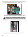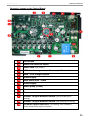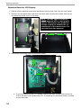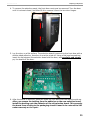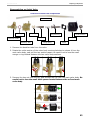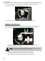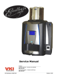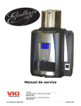
1
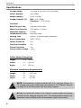
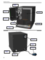
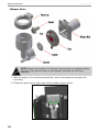
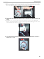
Service Manual Customer Service – 800.567.2951 VKI Publication# 100285-001 Technical Support – 888.854.0207 May 2015 Eccellenza Pod 2 Eccellenza Pod Table of Contents Contents Safety Information .............................................................................. 4 Specifications ...................................................................................... 6 Equipment Overview ........................................................................... 7 Rinse Cycles ........................................................................................ 9 Powder Rinse Cycle ........................................................................... 9 Brewer Rinse .................................................................................... 9 Maintenance ...................................................................................... 10 Daily.............................................................................................. 10 Weekly .......................................................................................... 10 Monthly ......................................................................................... 11 Every 6-12 Months .......................................................................... 11 Every 18 Months ............................................................................. 11 Sanitization – Milk System ............................................................... 12 Cleaning the Vacuum Duct (Powder System) ...................................... 13 Removing the Rear Panel .................................................................. 14 Removing the Top Panel .................................................................... 15 Removing the Front Panel ................................................................. 16 Draining the Water Tank ................................................................... 20 Replacing Components ...................................................................... 21 Brewer ........................................................................................... 21 Powder Dispensers .......................................................................... 23 Powder Dispenser Motors ................................................................. 25 Power Supply.................................................................................. 29 Control Board ................................................................................. 31 Connector Layout on the Control Board ......................................... 33 Selection Board or LCD Display ......................................................... 34 Water Tank .................................................................................... 39 Outlet Valve Manifold ....................................................................... 42 Disassembling the Dual Valve Manifold ......................................... 44 Disassembling an Outlet Valve ..................................................... 45 Inlet Valve ..................................................................................... 47 Air Pump ........................................................................................ 49 Replacing the Inline Check Valve .................................................. 50 Water Pump ................................................................................... 51 Powder Dispenser and Waste Bin Detection Switches ........................... 53 Whipper Motor ................................................................................ 54 Whipper Vacuum Fan ....................................................................... 59 Exhaust Fan ................................................................................... 61 Main Power Components .................................................................. 62 Fuse Holder (15 Amp) ................................................................. 63 Service Cord .............................................................................. 63 Main Power Switch ..................................................................... 64 Installing the Coin Changer System .................................................. 65 Install the Coin Changer Assembly .................................................... 68 Test the Machine and the Coin Changer System .................................. 69 Updating Equipment Firmware .......................................................... 70 Software Installation ....................................................................... 70 Hardware Installation ...................................................................... 70 Loading Programs onto the Load-n-Go Programmer ............................. 71 Loading New Firmware into the Eccellenza Pod ................................... 74 Error Messages.................................................................................. 77 Wiring Diagram ................................................................................. 79 Information in this document is subject to change without notice. 3 Eccellenza Pod Safety Information Safety Information Your safety is very important to us. It is imperative that you read and understand this safety information before proceeding with the installation, operation or servicing of this coffee maker. This equipment must be used specifically for the purpose for which it is designed. The manufacturer is not responsible for damage or injury resulting from improper use of this equipment. Always switch the machine power OFF and disconnect the service cord from the wall outlet when servicing this equipment, unless stated otherwise. This coffee maker is designed for indoor use ONLY and must never be installed outdoors. The installation of this equipment must comply with all municipal, state/provincial, and federal electrical and plumbing codes. Installation and servicing of this equipment must only be performed by qualified personnel. Do not attempt to install or service this equipment if you are not qualified as it may result in personal injury. There are no userserviceable parts inside the equipment. Do not attempt to lift or move this equipment by yourself. Use a hydraulic lift (or similar) or have a colleague provide assistance. This equipment must be installed in a location with an ambient temperature between 5°C-35°C (40°F-95°F). The main water supply pressure must be between a minimum of 20psi and a maximum of 100psi. This equipment must be positioned so that the wall plug and the main power switch are both easily accessible. Do not connect the coffee maker to a voltage supply other than the voltage indicated on the serial number decal. Do not immerse this coffee maker or any part of this equipment in liquid. Do not install the equipment in an area where water spray is present. This coffee maker must be installed securely on a level surface. If it does not appear to be a stable location, select another installation location. Keep hands clear of the dispensing area at the front of the coffee maker. Liquids being dispensed are extremely hot and can cause severe burns. Never disconnect the coffee maker by pulling on the service cord, and never use the coffee maker if the service cord is damaged. 4 Eccellenza Pod Safety Information If the service cord is damaged, it must be replaced with a new service cord that is available from your distributor or the manufacturer of this equipment. This equipment uses low voltage DC powered valves and motors. Do not connect components to a voltage supply other than the voltage indicated on their specifications. Never attempt to override the safety features incorporated into the equipment. They are there for your protection and should never be bypassed under any circumstances. Always switch the power off and disconnect the service cord when cleaning the interior of the coffee maker. Components inside the coffee maker can cause electrical shock resulting in personal injury. If the coffee maker is not working properly or appears to have a fault, switch off the power, disconnect the service cord and call an authorized technician immediately for service. Only qualified personnel should perform service on this equipment. Use caution when servicing the water heater or the outlet valves as they may be extremely hot and can cause severe burns. Use caution when working inside the coffee maker as there may be sharp edges on some components that can cause cuts. To prevent electrical shock, remove all jewelry (rings, watches, etc.) when servicing the coffee maker. Do not allow children to access this equipment. They are not aware of the potential dangers that exist. Never use ammonia based cleaners on machine surfaces as they will become discolored and/or damaged permanently. Use milder cleaning products, such as dish soap. Unauthorized modifications made to this coffee maker can result in serious personal injury and/or damage to the equipment, and voids all warranties and certifications. 5 Eccellenza Pod Specifications Specifications Voltage Rating 120 Volts AC @ 60hz (120 Volt Model) Heater Wattage 1400 Watts Weight (empty) 55 lbs (25 kg) Powder Capacity (2) Milk - 1 lb (450g) Chocolate – 1.2 lb (550g) Cup Sizes 3 Brew Time per Cup Less than 60 seconds Water Tank Capacity 0.79 gallons (3 liters) Waste Bin Capacity 50 Pods Temperature Control Electronic Probe Heating Time Approx. 15 minutes after installation Brew Temperature 198°F (92°C) Heater Protection Yes Overflow Protection Yes Circuit Protection Yes Certifications/Listings cCSAus Coffee Maker Dimensions Height: 17.8” (45 cm) Width: 15” (38 cm) Depth: 21 ” (53 cm) Minimum Installation Requirements Height: 18” (45.5 cm) Width: 15” (38 cm) Depth: 24” (61 cm) NOTE: This machine is factory preset with U.S. settings (Preset 1). To change this preset, follow the instructions in the “Presets” section on page 28 of the Eccellenza Pod Operating manual. NOTE: Any references made in this manual to coffee blends and powder products are for example purposes only. The actual products used in the equipment may be different than the examples used in this manual. 6 Eccellenza Pod Equipment Overview Equipment Overview LCD Display (2 x 20 characters) Strength Selection Buttons (Regular or Bold) Cup Size Selection Buttons (Small, Regular, Large) Front Fascia and Beverage Selection Area START button (starts brewing process) Door Lock LCD Screen Pod Door Selection Panel Cup Stand / Drip Tray 7 Eccellenza Pod Equipment Overview Powder Hoppers Door Lock Pod Door Set-Up Button Whipper Waste Bin Cup Stand / Drip Tray Exhaust Fan Main Power Switch Service Cord Water Inlet Valve 15A Fuse 8 Eccellenza Pod Rinse Cycles Rinse Cycles WARNING: Place a large cup under the dispensing spout area to catch the water that is dispensed during the rinse cycle. Powder Rinse Cycle NOTE: The powder rinse cycle is triggered automatically and is mandatory after removing and replacing the powder hoppers, or if the waste bin is removed for more than 10 seconds (default setting). To access the powder rinse cycle, 1. Enter the Set-Up mode and scroll to the Powder Rinse menu. 2. Place a large cup or leak-proof container under the dispensing spout. 3. Press the Enter () button to begin the rinse cycle. 4. Repeat step #3 if more rinsing is required. NOTE: The Powder System rinse menu automatically appears after the powder hoppers have been removed, refilled and replaced. Performing this cycle is mandatory and once it is completed, the machine will automatically revert to Standby (ready) mode. Brewer Rinse 1. Select the coffee beverage and press the Enter () button to open the brewer. 2. Instead of inserting a coffee pod into the brewer, insert the special brewer cleaning tablet into the brewer. 3. Press the Enter () button to activate the vend cycle. The hot water dissolves the cleaning tablet, which in turn cleans all of the areas in the brewer system with which it comes into contact. 4. Make several vends afterwards (without inserting anything into the brewer) to rinse out the cleaning solution. 5. Make one final vend using a coffee pod to test the brewer. 9 Equipment Overview Eccellenza Pod Maintenance To keep the equipment running efficiently and at peak performance, the following maintenance procedures must be performed at their specified intervals. It is recommended that equipment maintenance be scheduled at a time that would be the least disruptive to your customers. Whenever possible, replace the components requiring maintenance with new or refurbished ones, and then refurbish the older components at your shop. CAUTION: Never use ammonia based cleaners on machine surfaces as they will become discolored and/or damaged permanently. Use mild cleaning products, such as dish soap. Daily ► Empty the Drip Tray – empty the contents of the drip tray and rinse the tray and grill under clean running water. ► Empty the Waste Bin – empty the contents of the waste bin. ► Refill the Powder Hoppers – top off the powder hoppers. ► Perform a Whipper Rinse Cycle – this should be done immediately after refilling the powder hoppers to flush any product that may have fallen into the whipper. ► Wipe Exterior and Countertop – using the clean towel, wipe any coffee grounds and spills from the exterior of the machine and the countertop. Weekly ► Wipe Interior Walls and Door - using the clean towel, wipe any spills from the interior of the machine and the front door. ► Perform a Whipper Rinse Cycle – this should be done immediately after refilling the powder hoppers to flush any product that may have fallen into the whipper. ► Wipe Exterior and Countertop – using the clean towel, wipe any coffee grounds and spills from the exterior of the machine and the countertop. 10 Eccellenza Pod Maintenance Monthly ► Clean the Whipper System – disassemble the whipper system and clean the components with hot water. ► Clean the Brewer – to clean the brewer, make a vend as you normally would, however, instead of inserting a coffee pod into the brewer, you need to insert a special cleaning tab. The hot water dissolves the cleaning tab, which in turn cleans all of the areas in which it comes into contact. Make several vends afterwards (without inserting anything into the brewer) to rinse out the cleaning solution. Make one final vend using a coffee pod to test the brewer. ► Clean Hoses and Spouts – clean the exterior of all the product hoses and spouts with a wet towel. ► Thoroughly Clean the Interior – clean the interior walls, base and components with a clean wet towel. Every 6-12 Months ► Clean the Powder Hoppers – the hoppers should be emptied of product and given a thorough cleaning to remove stains and deposits that may have accumulated inside them. ► Clean the Brewer – to clean the brewer, make a vend as you normally would, however, instead of inserting a coffee pod into the brewer, you need to insert a special cleaning tab. The hot water dissolves the cleaning tab, which in turn cleans all of the areas in which it comes into contact. Make several vends afterwards (without inserting anything into the brewer) to rinse out the cleaning solution. Make one final vend using a coffee pod to test the brewer. ► Delime the Water Tank - to minimize servicing time, replace the water tank with a tank that has already been delimed, then clean the removed tank at the shop and use it the next time a tank replacement is required. ► Clean the Outlet Valves - to minimize servicing time, replace the outlet valves with valves that have already been cleaned, then clean the removed valves at the shop and use them the next time a valve replacement is required. ► Replace the Water Filter – the water filter should be replaced at least once a year, or when the water flow rate through the filter has decreased. This is an indication that the filter is starting to clog. Every 18 Months ► Replace the hose and grommet in the water tank – the 4" hose and the grommet that connect to the heat exchange tube inside the water tank, and the water pump tube elbow on the tank lid, will get harden and brittle over time and must be replaced. 11 Eccellenza Pod Equipment Overview Sanitization – Milk System Should the Eccellenza Pod’s milk system require sanitization, all of the following components must be removed and soaked in a sanitizing solution for 30 minutes. • • • • • Drip tray & grill Spouts Product hoses Whipper hose Whipper components NOTE: When ready for use, the end-use concentration of all quaternary chemicals in the solution is not to exceed 200ppm of active quaternary compound. To perform a sanitization of the machine components that have an impact on the milk system, a large leak-proof container, a spray bottle and SC Johnson J-512 sanitizer are required. 1. Fill the leak-proof container with a mixture of water and sanitizer – the mixture is 2ml of sanitizer per liter of water. 2. Remove the components identified above from the machine. 3. Place them inside the container with the sanitizing solution. Let them soak for 5 minutes. 4. While the components soak, fill a spray bottle with the sanitizing solution (2ml sanitizer per liter of water). 5. Lightly spray the solution to the exterior of the machine, the interior walls and interior of the front door, the whipper blade and base, and to the counter-top. Do not wipe away the solution – let it dry naturally. 6. After their 5 minute soak, remove the components from the leak-proof container and rinse them with clean warm water. 7. Re-install all of the components back into the machine. 12 Eccellenza Pod Maintenance Cleaning the Vacuum Duct (Powder System) 1. Open the front door and remove the two powder dispensers. 2. Lift the front of the upper vacuum duct plate (in the center of the dispenser base), and pull it towards you to remove it. 3. Remove the steam trap from the whipper system. 4. Lift the front of the lower vacuum duct plate and pull it towards you to remove it. 5. Rinse and thoroughly dry both the upper and lower vacuum duct plates. To install the vacuum duct plates, follow these same instructions in the reverse order. 13 Equipment Overview Removing the Rear Panel 1. Loosen the four screws securing the machine’s rear panel in place. 2. Lift and remove the rear panel. 3. Disconnect the inline wiring connector for the exhaust fan. 14 Eccellenza Pod Eccellenza Pod Maintenance Removing the Top Panel 1. Remove the four screws securing the machine’s top panel in place. There are two screws on each side of the panel. 2. Lift and remove the top panel. NOTE: When re-installing the top panel, make certain that the side with the protective film underneath is installed at the rear left (as illustrated below). 15 Equipment Overview Eccellenza Pod Removing the Front Panel 1. Remove the waste bin and open the front door of the machine. 2. Remove the top panel from the machine. 3. Remove the two screws securing the left side of the front panel. 4. Disconnect the wiring connector going to the front panel (this is for the LED wiring). 16 Eccellenza Pod Maintenance 5. Gently lift the front panel and pull the top of it towards you. This will unhook the right side of the front panel from the machine wall. 6. Disconnect the three hoses from their respective spouts. - Powder Hose - Coffee Hose - Hot Water Hose 7. Remove the front panel. 17 Eccellenza Pod Equipment Overview 8. To install the front panel, install notch at the bottom on the panel onto the lower post on the right wall of the machine. 9. Connect the three product hoses to the three spouts on the bottom of the front panel. - Powder Hose - Coffee Hose - Hot Water Hose 18 Eccellenza Pod Maintenance 10. Swing the top of the panel forward and install the notch at the top of the panel onto the upper post on the right wall of the machine. 11. Secure the left side of the front panel to the machine using two screws. 12. Connect the front panel wiring. 13. Install the top panel and the waste bin. 19 Eccellenza Pod Equipment Overview Draining the Water Tank 1. Remove the back panel and the top panel from the machine. 2. Remove the drain hose (and valve) from its clip. 3. With the drain valve closed, remove the black drain plug from the drain valve. Closed Open 4. Place the drain hose valve into a leak-proof container and open the valve to drain the water tank. 5. Once the tank has drained, close the drain valve and re-install the drain plug onto the valve. 6. Install the drain hose onto its clip, and re-install the back panel and top panel. 20 Eccellenza Pod Replacing Components Replacing Components Brewer 1. Remove the waste bin and open the front door of the machine. 2. Remove the top panel and remove the front panel. 3. Disconnect the inline connector on the wiring harness. 4. Disconnect the brewer outlet hose a. Remove the safety clip. b. Push in the collar on the quick-connect fitting and pull out the elbow. 21 Replacing Components Eccellenza Pod 5. Remove the two wing nuts securing the brewer to the machine. 6. Lift and remove the brewer assembly from the machine. To install the brewer back into the machine, follow these same instructions in the reverse order. WARNING: When reconnecting the outlet elbow to the brewer, you must install the safety clip under the collar of the fitting to secure the elbow in place. 22 Eccellenza Pod Replacing Components Powder Dispensers 1. With the machine front door open, rotate the spout caps to block each of the powder dispenser spouts. 2. Rotate the spout caps to block each of the powder dispenser spouts. 3. Remove the powder dispenser by sliding them out towards you. 23 Replacing Components Eccellenza Pod 4. Fill the replacement dispensers with their respective powders. Never pack the powders into the dispensers as this causes inconsistent gram throws, and in some cases, can cause a dispenser to jam. 5. When installing the powder dispensers, they must be properly engaged with the coupling on the motor (A) and the detection switch (B). If this is not done correctly, the machine displays a message asking you to install the powder 1 and/or the powder 2 dispenser(s). 6. Once installed, rotate the spout caps to unblock each of the dispenser spouts. NOTE: To reduce the risk of powder ‘bearding’ or clogging of the dispenser spouts, make sure the spouts are completely turned down (as illustrated above). A retainer on the upper vacuum duct plate will stop the spouts when they are in their proper position. 7. When the machine is put back into service, a powder rinse cycle will be required to flush any powder that may have fallen into the whipper bowl. 24 Eccellenza Pod Replacing Components Powder Dispenser Motors 1. Drain the water tank as you will need to move it during this process. 2. Remove the top panel, the rear panel and the two powder dispensers. 3. Remove the whipper support plate (four screws) to access the motor wiring. 4. Disconnect the inline wiring connector for the motor that is to be replaced. The blue wires are for the powder 1 motor and the red for the powder 2 motor. 25 Replacing Components Eccellenza Pod 5. Remove the screws securing the motor that is to be replaced (there are two screws per motor). 6. Locate the dispenser motors on the other side of the metal wall shown above. They are between the tank and the wall. 26 Eccellenza Pod Replacing Components 7. Carefully lift and slightly pull the empty water tank away from the wall on which the motors are installed. Do not force it away from the wall. 8. To remove the Powder 2 motor, pull it towards the water tank and turn it slightly so that both the coupling and the coil of the motor clear the wall. 27 Replacing Components Eccellenza Pod 9. To remove the Powder 1 motor, pull it towards you and twist it slightly clockwise. It may be necessary to turn it into the hot water hose to get the motor coupling and coil to clear the wall. 10. To install the new motors, follow this procedure in the reverse order. 11. After the new motors are mounted onto the wall, reseat the water tank back into its proper position. 12. Inspect the hoses on the two outlet valves to make certain they are properly secured to the valves. 13. Inspect the outlet end of the hot water and powder hoses to make certain they are properly secured to their respective component. 14. When reconnecting the inline power wiring connectors to their motors, make certain the blue wires are on the powder 1 motor and the red on the powder 2 motor. 15. Test the machine to make certain everything is functioning properly. 28 Eccellenza Pod Replacing Components Power Supply 1. Switch off the machine power and disconnect the service cord from the wall outlet. 2. Remove the waste bin and remove the rear panel. 3. The three screws that secure the power supply in place are located on left wall on the waste bin area. These screws require a smaller tipped Philips screwdriver than the one typically used for the other screws in the machine. 4. Slightly loosen the three screws securing the power supply to the wall. Do not remove these screws. 5. From the rear of the machine, lift up the power supply and pull it away from the wall on which it is mounted. Once cleared from the wall, pull the power supply towards you. 6. Disconnect the two wiring harnesses from the power supply. 29 Replacing Components Eccellenza Pod 7. Connect the two wiring harnesses to the new power supply (see image above). 8. Install the three mounting screws to the rear of the power supply (if missing). 9. Install the power supply onto the keyhole slots on the inner wall of the machine. 10. Drop the three screws into the keyhole slots and then tighten the screws. 11. Install the rear panel and the waste bin. 12. Connect the service cord to the wall outlet and switch the machine power on. 13. Test the machine to make certain everything is functioning properly. 30 Eccellenza Pod Replacing Components Control Board 1. Switch off the machine power and disconnect the service cord from the wall outlet. 2. Remove the rear service panel. 3. The control board is located on the inside of the right wall. Remove the screw that secures the control board in place. 4. Move the board to the left until it clears the metal edge and pull it towards you. 31 Replacing Components Eccellenza Pod 5. As you are removing the board, disconnect the wiring from their respective connectors on the board. 6. The new board can now be installed. As you are installing the new board, connect the wiring to their respective connectors on the board (see next page for layout of the board connectors). NOTE: The wiring connectors are matched with their respective connectors on the board assembly, reducing the likelihood of making connection errors. Make certain to push the wiring connectors firmly into the board connectors, ensuring that they are locked in place. 7. To secure the board in place, lock the rear of the board bracket into the slot on the metal shelf. Once done, secure the front of the board bracket with a screw. 8. Install the rear panel, connect the service cord to the wall outlet and power up the machine. 9. Test the machine to make certain everything is functioning properly. 32 Eccellenza Pod Replacing Components Connector Layout on the Control Board LCD Screen Waste bin detection switch Water tank (low power) LED’s for beverage area and brewer pod illumination MDB – coin changer system Power supply Main power wire – black Power supply Water pump (coffee) Powder motors Brewer Powder 2 hopper detection switch (yellow marking on wiring) Powder 1 hopper detection switch (red marking on wiring) Firmware update connector (for loading new firmware) Inset shows older style connector. 33 Eccellenza Pod Replacing Components Selection Board or LCD Display 1. Switch off the machine power and disconnect the service cord from the wall outlet. 2. Remove the top panel and open the front door and remove the screws that secure the selection board cover to the door. NOTE: The two upper screws are each equipped with a small plastic spacer. This spacer also holds the screws in place to simplify the reinstallation of the board cover. Do not lose these two spacers! 3. Disconnect the wiring from the selection board. a. If you are replacing the LCD display, remove the two screws that secure the LCD to the door and replace the LCD. If replacing the selection board, proceed to the next step. 34 Eccellenza Pod Replacing Components 4. To remove the selection panel, the front door must now be removed. Turn the door until it is almost closed, and then lift it to remove it from the two door hinges. 5. Lay the door on a flat surface. The selection board is secured to the front door with a double-sided adhesive, therefore it must be pried off. Using a flat head screwdriver, insert the tip between the selection board and the door, and carefully and slowly pry the board off the door. 6. After the board is removed, place the board on your table with the adhesive side up. After you remove the backing from the adhesive on the new selection board, install the backing onto the adhesive of the old selection board. This prevents the board from sticking to the packaging should it need to be returned to VKI under warranty or for repair. 35 Replacing Components Eccellenza Pod 7. Peel off the backing from the adhesive on the new selection board and install the backing onto the old selection board. 8. The inside of the front door is equipped with four small alignment tabs (one for each corner of the board). Lightly place the selection board onto these four alignment tabs. Once satisfied that it is in the proper position, apply light pressure with your fingers to the back of the board to make it stick to the door. Avoid touching any of the IC chips when applying the pressure. 9. Connect the wiring from the LCD to the selection board. 36 Eccellenza Pod Replacing Components 10. Re-install the front door onto the machine by sliding it down onto the hinges. 11. Connect the wiring from the machine onto the front selection board. NOTE: This particular connector is square (2 rows x 2 columns) and must be installed correctly. Pin one on the connector is identified with a small arrow and this arrow must be pointing to the top left pin on the board connector. 12. Switch the machine power ON, and check the contrast on the LCD screen. If the contrast needs to be adjusted, it can be done using the potentiometer next to the LCD connector on the selection board. Once set, switch the machine power OFF. 37 Replacing Components Eccellenza Pod 13. Make sure the two spacers are installed on the two top screws on the metal selection board cover. Do not install the board cover if these spacers missing! 14. Install the selection board cover onto the selection board and secure it in place with four screws – including the spacers on the two top screws. 15. Close the front door, reconnect the service cord to the wall outlet and power up the machine. 16. Test the machine to make certain everything is functioning properly. 38 Eccellenza Pod Replacing Components Water Tank 1. Switch the machine power off and unplug the service cord. 2. Turn off the water supply, and drain the water tank. 3. Remove the machine top panel and the rear panel. 4. Disconnect the wiring to the three water level probes, remove the temperature probe, and disconnect the water pump tube from the barbed elbow on top of the water tank. 5. Disconnect the valve wiring and the valve outlet hoses. Be careful that the hoses do not fall through their cutouts in the center wall. 39 Replacing Components Eccellenza Pod 6. Open the clamps and remove the inlet hose and the drain hose. 7. Lift the water tank up and out of the machine. 8. To install the replacement water tank, lower the tank onto its front and rear supports. Make certain that the tab on the bottom of the water tank is locked into the slot in the metal shelf. 9. Connect the inlet hose and the drain hose to the bottom of the water tank and secure them with plastic clamps. 10. Connect the outlet hoses onto the outlet valves. 40 Eccellenza Pod Replacing Components 11. Connect the wiring onto the outlet valves a) White pair ► Powder Valve b) Yellow pair ► Hot Water Valve 12. Connect the wiring to the three water level probes, install the temperature probe, and connect the water pump tube to the barbed elbow on top of the water tank. 13. Turn on the water supply, connect the service cord to the wall outlet and switch on the machine power. 14. Allow the water tank to fill and check for leaks. 15. Test the machine to make certain everything is functioning properly. 16. Install the rear panel and the top panel. 41 Replacing Components Eccellenza Pod Outlet Valve Manifold 1. Switch the machine power off and unplug the service cord. 2. Turn off the water supply, and drain the water tank. 3. Remove the rear panel and the top panel. NOTE: The Eccellenza Pod machine is equipped with a dual outlet valve manifold (two stacked outlet valves in one assembly - one for the powder and one for hot water). 4. Disconnect the valve wiring and the valve outlet hoses. Be careful that the hoses do not fall through their cutouts in the center wall. 5. Lift the water tank and pull the outlet valve manifold from the valve port on the water tank. The tank must be lifted high enough so that the valve clears the side wall. Use caution as there may still be a bit water remaining behind the valve when you remove it – this water may be extremely hot. 42 Eccellenza Pod Replacing Components 6. Install the new valve manifold onto the valve port of the water tank. Make certain the two O-rings are installed on the valve inlet and that the valve is pushed into the valve port as far as it can go. 7. Lower the water tank back onto its front and rear supports. 8. Connect the outlet hoses onto the outlet valves. 9. Connect the wiring onto the outlet valves a) White pair ► Powder Valve b) Yellow pair ► Hot Water Valve 10. Turn on the water supply, connect the service cord to the wall outlet and switch on the machine power. 11. Allow the water tank to fill and check for leaks. 12. Test the machine to make certain everything is functioning properly. 13. Install the rear panel and the top panel. 43 Replacing Components Eccellenza Pod Disassembling the Dual Valve Manifold 1. Remove the two black clips (top and bottom center clips) securing the two valves together, and gently pull the two valves apart. 2. Remove the two clips securing the valve end cap to the valve body and gently remove the end cap. There are two o-rings located between the valve body and the end cap, and they must be replaced when re-assembling the valve. 3. Remove the two clips securing the valve inlet to the valve body and gently remove the inlet. There is an o-ring located between the valve body and the inlet, and it must be replaced when re-assembling the valve. 44 Eccellenza Pod Replacing Components Disassembling an Outlet Valve Overview of Outlet Valve Components Breather Tube O-Ring Diaphragm Hex Nut & Washer Plunger Housing Coil Plunger Valve Body - Outlet Valve Body - Main Plunger Spring Spacer 1. Remove the breather tube from the valve. 2. Rotate the outlet section of the valve body counterclockwise to release it from the main valve body, and pull the two sections apart. Be careful not to lose the small orange o-ring located between the two valve body sections. 3. Remove the hex nut from the coil, and remove the coil from the main valve body. Be careful not to lose the small black spacer located between the coil and main valve body. 45 Replacing Components Eccellenza Pod 4. On the main valve body, twist the ground tab clockwise to free the plunger housing, and pull it away from the main valve body. This exposes the plunger and assembly. Be careful not to lose the small spring inserted into the end of the plunger. 5. Pull the plunger assembly out of the main valve body. This exposes the diaphragm installed onto the tip of the plunger. 6. Remove the diaphragm by pulling it off of the tip of the plunger. The spring on the other end of the plunger can also be removed. To re-assemble the outlet valve, follow these same instructions, but in the reverse order. 46 Eccellenza Pod Replacing Components Inlet Valve 1. Switch the machine power off and unplug the service cord from the wall outlet. 2. Disconnect the water supply and remove the inlet fitting from the inlet valve. 3. Remove the rear panel from the machine and drain the water tank. 4. Remove the circle clamp and remove the inlet valve’s outlet hose. 5. Disconnect the power wires from both of the inlet valve solenoids. 6. Compress the clip on the right side of the inlet valve, and push the right side of the valve through the opening in the metal and remove the valve. 47 Replacing Components Eccellenza Pod 7. To install the new valve, lock the valve’s left side clip to the left of the opening in the metal, and then push the right side of the valve until the right side clip locks in place. 8. Secure the valve outlet hose to the new inlet valve with a new Oetiker clamp. 9. Connect the power wires to the valve solenoids. 10. Attach an inlet fitting to the valve and connect the water supply. 11. Connect the service cord to a wall outlet and switch the machine power on – the water tank will start filling. 12. Check for leaks and, if any are present, repair them immediately. 13. Test the machine to make certain everything is functioning properly. 14. Install the rear panel onto the machine. 48 Eccellenza Pod Replacing Components Air Pump 1. Remove the top and rear panels. 2. The air pump is located on the left of the wall behind the brewer (the water pump is also located in this area, on the right side). 3. Cut the tie-wrap securing the air pump to the wall and disconnect the power wires and the outlet hose from the pump. 4. Connect the power wires to the new air pump. Note that this is a DC powdered pump and the wires must be placed on the correct terminals. Connect the white wire (positive) to the terminal with the ‘+’ marking, and connect the black wire (ground) to the other terminal. - + 49 Replacing Components Eccellenza Pod 5. Secure the air pump to the opening on the metal wall using a large tie-wrap. 6. Connect the outlet hose to the air pump. 7. Test the machine to make certain everything is functioning properly. Replacing the Inline Check Valve The air pump is equipped with a check valve that prevents water from flowing into the pump, but still allows air to flow out of the pump. To replace this check valve; 1. Cut the two tie-wraps on the check valve and pull the hose off each side. The check valve has now been removed. NOTE: The check valve must be installed in the proper direction or you risk damaging it and/or other components in the equipment. 2. Connect the pump side tubing to the flat side of the check valve. 3. Connect the other tube to the tapered side of the check valve. 4. Secure the tubing with a tie-wrap on each side of the check valve. 50 Eccellenza Pod Replacing Components Water Pump 1. Remove the top and rear panels. 2. Disconnect the water pump inlet hose from the fitting on top of the water tank. 3. Disconnect the water pump outlet hose from the inlet of the “Y” fitting (on the brewer side of the wall). 4. Disconnect the two power wires from the water pump. 5. Remove the four screws securing the water pump to the wall, and remove the pump. 51 Eccellenza Pod Replacing Components 6. Place the new water pump on the wall and secure it in place with four screws. 7. Connect the power wires to the water pump. Note that this is a DC powdered pump and the wires must be placed on the correct terminals. Connect the red wire (positive) to the terminal with the red marking, and connect the blue wire (ground) to the other terminal. + 8. Connect the water pump outlet hose to the inlet of the “Y” fitting (on the brewer side of the wall. 9. Connect the water pump inlet hose to the fitting on top of the water tank. 10. Test the machine to make certain everything is functioning properly. 11. Install the top panel and the rear panel onto the machine. 52 Eccellenza Pod Replacing Components Powder Dispenser and Waste Bin Detection Switches Three detection switches are used in this machine – one to detect the presence of the waste bin, and the other two to detect the presence of the powder dispensers. Should you need to replace any one of these detection switches: 1. Remove the waste bin, the two powder dispensers, the top panel and the rear panel. 2. Disconnect the wiring connector at the rear of the switch that is to be replaced. 3. Compress the clip at the front of the switch to unlock it and remove the switch. 4. Press the new switch into the cutout in the metal until the clip locks it in place. 5. Connect the wiring connector to the rear of the switch. 6. Re-install all of the panels, the powder dispensers and the waste bin and test the machine to make certain everything is functioning properly. 53 Replacing Components Eccellenza Pod Whipper Motor NOTE: Replace the impeller if it has been removed and re-installed multiple times as it may become loose on the whipper shaft and fall off during operation. 1. With the power to the machine switched off, remove the waste bin and open the front door. 2. Rotate the spout caps to block each of the powder hopper spouts. 54 Eccellenza Pod Replacing Components 3. Disconnect the outlet hose from the whipper chamber. 4. Remove the four screws securing the whipper plate to the machine and remove it. 5. Disconnect the inline power connector from the whipper motor. 6. Remove the steam trap (vacuum cap) from the whipper chamber. 55 Replacing Components Eccellenza Pod 7. Turn the small handle on the locking ring (on the whipper base) to the right until it stops. This unlocks the whipper chamber from the whipper base, allowing it to be pulled off. 8. Remove the screw securing the top of the whipper base to the machine wall, and turn the handle on the locking ring to the left until it stops. 56 Eccellenza Pod Replacing Components 9. While pressing down on the locking clip at the front of the plate, press down on the clip at the rear of the plate, and push it out through to the front. 10. Remove the base, gasket and impeller from the old motor and transfer it to the new motor. 11. Install the new motor into the cutout in the whipper mounting plate. Install the bottom of the assembly first, and then push the top of the assembly into the cutout until the plastic clip locks it in place. 12. Turn the handle on the locking ring completely to the right and secure the base to the wall with a screw. 57 Replacing Components Eccellenza Pod 13. Insert the whipper chamber into the base (making sure to also insert the chamber’s inlet into the adaptor), and turn the handle on the locking ring to the center position to secure the chamber. 14. Install the steam trap (vacuum cap) onto the whipper chamber. 15. Connect the inline wiring connector that supplies power to the whipper motor. 16. Install the whipper support plate onto the machine and secure it with four screws. 17. Connect the whipper outlet hose, and rotate the spout caps to open each of the powder hopper spouts. 18. Close the front door and install the waste bin. 19. Power on the machine. A rinse cycle is now required. 20. Perform a “Powder Rinse” cycle to flush any powder that may have fallen into the whipper chamber. 58 Eccellenza Pod Replacing Components Whipper Vacuum Fan 1. Switch off the machine power and disconnect the service cord from the wall outlet. 2. Remove the waste bin. 3. Disconnect the outlet hose from the whipper chamber. 4. Remove the four screws securing the whipper plate to the machine and remove it. 5. Disconnect the two power wires and the vacuum hose from the vacuum fan. 59 Replacing Components Eccellenza Pod 6. In the waste bin area, loosen the two screws securing the fan to the wall. It is not necessary to remove these screws. 7. Lift the fan and pull it to the left to remove it. 8. Install the new whipper vacuum fan and tighten the two screws to secure it to the wall. 9. Connect the two power wires and the vacuum hose to the fan. 10. Re-install the whipper plate and secure it with the four screws. 11. Test the machine to make certain everything is functioning properly. 60 Eccellenza Pod Replacing Components Exhaust Fan 1. With the power to the machine switched off, remove the machine’s rear panel. 2. Disconnect the inline wiring connector for the exhaust fan 3. The fan is secured to the rear panel with four screws and hex nuts. Remove the four exterior screws using a screwdriver, while holding their respective interior hex nuts with a nut driver or small wrench. To install the new exhaust fan, follow these same instructions in the reverse order. 61 Replacing Components Eccellenza Pod Main Power Components The service cord must be disconnected from the wall outlet when servicing these components. They remain live even when the main power is switched off at the rear of the machine. The main power components are all secured to the bottom rear of the machine. Removing the rear panel provides access to the fuse holder, the main power switch and the service cord. 1. Switch the machine power off and disconnect the service cord from the wall outlet. 2. Remove the rear panel of the machine. 3. The main power components are located at the bottom rear of the machine. 4. Replace the faulty component (see next two pages for detailed instructions on replacing each of these components). 62 Eccellenza Pod Replacing Components Fuse Holder (15 Amp) a. Disconnect the wiring from the fuse holder. b. Loosen the plastic hex nut that secures the fuse holder to the machine (see image). c. Remove the fuse holder and replace it with the new one. d. Transfer the fuse and the cap from the old fuse holder onto the new one (if required). e. Install the new fuse holder and secure it to the machine with the hex nut. f. Connect the wiring to the new fuse holder. Service Cord a. Disconnect the service cord wiring from the main power switch (switch tabs 1a and 2a). b. Disconnect the ground terminal from the grounding post on the metal wall. c. Compress the strain relief and pull the service cord out of the opening in the metal. d. Install the strain relief onto the service cord and insert the end of the new service cord through the opening in the metal. e. Connect the service cord wiring to the main power switch (switch tabs 1a and 2a). f. Connect the ground terminal to the grounding post on the metal wall. g. Compress the strain relief and pull the service cord into of the opening in the metal. 63 Replacing Components Eccellenza Pod Main Power Switch a. Disconnect the wiring from the main power switch. b. Compress the clips on the top of the switch, and push the switch through the opening in the metal. c. Insert the new switch into the opening on the metal, and snap it in place to secure it. d. Connect the wiring to the new power switch. i. Black wire (hot) -> connects to tab #1a on the switch ii. Black wires (hot) - dual terminal -> connects to tab #1 on the switch iii. White wires (neutral) -> connect to tabs #2 and #2a on the switch. 64 Eccellenza Pod Installing a Coin Changer System Installing the Coin Changer System The Eccellenza Pod uses the “MDB–Level 3” protocol to communicate with a compatible coin changer. VKI has thoroughly tested and validated ONLY the following coin changer for proper operation with the Eccellenza Pod (firmware 2.2 or higher): Coinco® - Guardian 6000 Series, Quantum Pro, CoinPro3 MEI® - Cashflow 7000 Series NRI® - Currenza C2 Conlux® - MCM5-1 It is highly recommended that you acquire the “Operation & Service” manuals for each of these changers from their manufacturer. This sophisticated changer is highly customizable and may require direct configuration through its own respective software, which is totally independent of the Eccellenza Pod software configuration. 1. Remove the two right side top panel screws, and remove the rear panel. 2. Disconnect and remove the exhaust fan from the original rear panel and install it onto the rear panel that accompanied the coin changer housing. 65 Installing a Coin Changer System Eccellenza Pod 3. Install the coin changer housing onto the right side of the machine and secure it by re-installing the two screws you removed from the top panel through the changer housing, the top panel and into the machine cabinet. For this operation, you will require a smaller stubby Philips screwdriver. 4. Connect one end of the supplied wiring extension to the MDB connector on the control board, and connect the other end to the wiring harness in the changer housing. 66 Eccellenza Pod Installing a Coin Changer System 5. Install the new rear panel to the back of both the machine and the coin changer housing. a. Make sure the cutout in the rear panel is installed over the wiring harness so as not to pinch the wiring between the cover and the machine chassis (the wiring should be sticking out of the cutout). Install the cover plate over the cutout to cover the wiring harness. b. Reconnect the exhaust fan wiring. c. Secure the rear panel onto the machine chassis using the screws provided. 67 Installing a Coin Changer System Eccellenza Pod Install the Coin Changer Assembly 1. Unlock the coin changer housing and pull the door open. 2. Loosen the three mounting screws on the inner wall of the housing. 3. Slide the coin changer over the three screws (there are three keyhole slots at the rear of the changer) and push down on it, making sure all three screws are inserted into the slot. 68 Eccellenza Pod Installing a Coin Changer System 4. Flip open the acceptor portion of the coin changer and tighten the three screws to secure the changer to the housing, and then close the acceptor portion. 5. Connect the coin changer wiring to the small connector in the changer housing. 6. Close and lock the door of the coin changer housing. Test the Machine and the Coin Changer System 1. To switch the machine from free mode to coin mode, enter the Set-Up mode and scroll to the Options menu and then select the Vending sub-menu and the Changer option. Change this setting to “On” to enable coin mode. 2. Insert several coins to test the coin changer system (insert more than the selling price of the beverage). The coins should be accepted and a credit will be displayed on the LCD screen. 3. Make a beverage selection and press the Start button to prepare the beverage. You should receive change if your credit exceeded the selling price of the beverage. 4. Insert a few more coins, only this time, press the coin reject button on the changer. The money inserted should now be returned to you in the coin return cup. 69 Error Messages Eccellenza Pod Updating Equipment Firmware To update the firmware in the Eccellenza Pod machine, a Load-n-Go handheld programmer (shown below) is required. Should multiple different firmware files become available for the Eccellenza Pod, you can load up to four of them onto this one programmer. NOTE: VKI Technologies does not sell this programmer. It can be purchased online at www.ccsinfo.com. Please visit this web site for more details. Software Installation 1. Insert the CD Rom provided into your computer drive. 2. Click on the ccsload folder and select setuccsload.exe. 3. Allow the installation process to complete. 4. Click on the USB-Drivers folder (on CD-Rom). 5. Select usbdrivers.exe and follow the instructions for installing the driver and adding the new hardware. 6. See the included Help File on the CD (CCSLoad.CHM) for more assistance after installation. Hardware Installation 1. Insert four AA batteries into the battery compartment in back of the Load-n-Go programmer. 2. Connect the Load-n-Go programmer to your PC via the USB cable provided. 3. Run the ccsload.exe software that was installed on your PC (a shortcut should have been left on your desktop). 70 Eccellenza Pod Error Messages Loading Programs onto the Load-n-Go Programmer 1. Connect the Load-n-Go programmer to your PC via the USB cable provided. 2. Run the ccsload.exe software that was installed on your PC to open the CSS Programmer Control Panel. 3. Once loaded, from the upper right area of the screen, select any of the four memory banks. 71 Error Messages Eccellenza Pod 4. Click on the Browse button and select the file from the Open dialog box (your PC) to be loaded into the programmer, and press the Open button. This step loads the file into the CSS Programmer Control Panel application. 5. Click on the Test button. A drop-down box opens with a list of compatible memory chips. From this list, you must select the PIC24FJ128GA006 memory chip. You must select the PIC24FJ128GA006 memory chip from the list displayed! If the proper chip is not selected, it will not be possible to update the machine’s firmware. 72 Eccellenza Pod Error Messages 6. Click on the “Write to Mem” button to write the specified file to the memory location that was selected. 7. The file will then be written to the programmer. A progress bar at the bottom of the window allows you to see how much of the file has been transferred. NOTE: Do not disconnect the programmer from the PC while the file is being written. 73 Error Messages Eccellenza Pod 8. After the file is written to the programmer, a confirmation message appears on the screen. If any errors prevented the file from being written, they will be displayed in this area. Also notice that at the lower right of the screen, it reads “Pass=1” – this indicates that one file has successfully passed the writing process. 9. If you are finished loading files into the programmer, we recommend that you close the CCS Programmer Control Software application on your PC first, and only then disconnect the USB cable from your PC. Loading New Firmware into the Eccellenza Pod 1. Switch off the power to the machine. 2. Remove the rear panel from the machine. 3. Locate the firmware update port in the center of the control board. Newer machines are equipped with an RJ25 connector (left image) and older machines use a special port on the control board (right image). 74 Eccellenza Pod Error Messages 4. On older machines, connect the special programming cable to the firmware update port in the center of the control board. Note that this connector must be installed in a specific way (illustrated below). On newer units, connect the phone type cable directly to the RJ25 connector on the control board. The three larger silver colored guide pins must align with the three contacts on the control board, and the four plastic clips on the connector must align with the four small holes in the control board. Once aligned, compress the sides of the connector slightly and push the connector onto the board until it locks in place. Newer machines (and control boards) are equipped with an RJ25 phone type connector. 75 Eccellenza Pod Error Messages 5. Connect other end of the cable to the programmer (uses a standard RJ25 telephone jack). 6. Switch the machine power on. 7. Press the “On/Off” button on the programmer. The green light will be on when the unit is powered. 8. Use the “Program Select” button to choose the memory bank in which your file was stored. One of the four LEDs will be illuminated to indicate the memory bank that is selected. 9. Press the “Load” button to start the firmware upload. The status LED will start flashing to indicate that the file is uploading. 10. When the upload is complete, the LED will stop flashing and turn green if the upload was successful or red if the upload failed. 11. If the upload was successful, switch off the power to the machine, disconnect the programming cable and switch the machine power back on. 12. If the upload failed, verify that you have the correct file on your PC and repeat the entire loading process (first from the PC to the programmer, and then from the programmer to the machine). NOTE: Once a file is loaded into the programmer, it will remain stored in the programmer until you write another file into that memory location. 76 Eccellenza Pod Error Messages Error Messages MESSAGE DISPLAYED CAUSE Beverage Unavailable A beverage cannot be dispensed. Brewer Error An error has been detected with the brewer. POSSIBLE REMEDIES • Make sure the waste bin is installed. • Make sure both of the powder hoppers are installed. • Verify the brewer motor wiring. • The brewer may be jammed. Repair or replace the brewer. • Press "START" () to cycle the brewer. • Reboot the machine (power off and on). Brewer Home Error. The brewer is not in the home or starting position. • The brewer may be jammed. Repair or replace the brewer. • An electrical connection to the brewer home switch is faulty. Button(s) Error An error has been detected with one of the selection buttons. • The front selection panel may need to be replaced. Call Key Operator The cashbox may be full. • Empty the cashbox and reset the Cashbox Total Counter Empty Waste Bin Waste bin may be full. Fill Powder 1 Powder 1 dispenser is low and required refilling. Fill Powder 2 Powder 2 dispenser is low and required refilling. • Reset the “Refill” message for the Powder 2 dispenser. Heating Water Water inside the hot water tank is heating. • Normal operating message and does not indicate an error. Insert Waste Bin The waste bin is missing. • Install the waste bin. Insert Powder 1 Powder 1 hopper is missing. • Install the powder 1 hopper. Insert Powder 2 Powder 2 hopper is missing. • Install the powder 2 hopper. Keypad Not Connected The keypad is not being detected. • Check the wiring to the keypad. • Empty the contents of the waste bin. • Reset the “Waste Bin” counter. • Refill the dispenser for powder 1. • Reset the “Refill” message for the Powder 1 dispenser. • Refill the dispenser for powder 2. • Empty and dry the overflow/cup tray. • Verify the water level probe adjustment. They may be set too high allowing too much water into the tank. Overflow Error A water overflow has been detected. • Water level probes may need to be cleaned. • Inlet valve may be leaking, constantly allowing water to enter the tank. Replace the inlet valve. • Water in the tank may be boiling. Lower the water temperature setting. 77 Eccellenza Pod Error Messages MESSAGE DISPLAYED CAUSE Overheat Error The water tank is overheating. Power Saving Mode – Press Start to Exit The machine is in Power Saving Mode. POSSIBLE REMEDIES • Check the temperature settings in the set-up. • The temperature probe may need to be replaced. • Press "START" () to exit Power Saving Mode. • Check the 15 amp fuse. Tank Not Heating Error The hot water tank is not heating. • Reset the thermal cut-off switch. • Verify wiring to heater element. • Check heater element. Temperature Probe Error The temperature probe is not functioning correctly. • Replace the temperature probe. Thermister Shorted Error The thermister is not functioning correctly. • Replace the thermister. Thermister Open Error The thermister is not functioning correctly. • Replace the thermister. • Clean the water level probes. Water Level Error The water tank is overfilling. • The water temperature may be too high – lower the temperature. • Inlet valve may be leaking – replace inlet valve. • At this point, the water tank is not full and this message has to be reset. To reset it, switch the power off and on. Water Source Error Indicates a problem with the main water supply not getting to the water tank. • If the problem persists, check all components on the water line (water filter, tubing, fittings, etc.). • Check inlet valve to make certain it is functioning properly. • In the case of a temporary disruption with the water supply, the coffee maker will reset itself after every hour. • The whipper motor may be jammed. Clean the whipper assembly. Whipper Error 78 An error has been detected with the whipper. • Verify wiring to the whipper assembly. • The whipper motor assembly may need to be replaced. Eccellenza Pod Service Manual Wiring Diagram 79 Service Manual 80 Eccellenza Pod