1
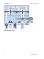
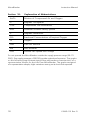
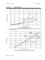
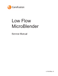
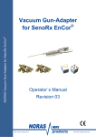
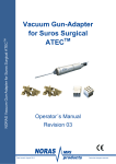
Low Flow MicroBlender and High Flow MicroBlender Instruction Manual MicroBlender Instruction Manual This document is protected by United States and International Copyright laws. This document may not be copied, reproduced, translated, stored in a retrieval system, transmitted in any form, or reduced to any electronic medium or machine-readable form, in whole or in part, without the written permission of CareFusion. Information in this document is subject to change without notice. This document is for informational purposes only and should not be considered as replacing or supplementing the terms and conditions of the License Agreement. © 2009–2010 CareFusion Corporation or one of its subsidiaries. All rights reserved. USA Authorized European CareFusion Representative 22745 Savi Ranch Parkway CareFusion Germany 234 GmbH Yorba Linda, California 92887-4668 Leibnizstrasse 7 97204 Hoechberg, Germany District Court Wuerzburg HRB7004 800.231.2466 tel +49.931.4972.0 tel +1.714.283.2228 tel +49.931.4972.423 fax +1.714.283.8493 fax carefusion.com Literature number: L2965–101 Revision D ii L2965–101 Rev. D Instruction Manual MicroBlender Contents Section 1: Introduction....................................................................... 1 Section 2: Operation Overview ........................................................... 2 Gas Inlets ........................................................................................ 3 Balance Module............................................................................... 3 Proportioning Module ..................................................................... 4 Alarm/Bypass .................................................................................. 4 Outlet Ports..................................................................................... 5 Bleed Outlet .................................................................................... 5 Section 3: Warnings, Cautions, and Notes............................................ 7 Section 4: Controls and Alarms ........................................................... 9 Section 5: Performance Checks ......................................................... 10 Low Flow MicroBlender Alarm / Bypass Check Reverse Flow Check.. 10 High Flow MicroBlender Alarm / Bypass Check ............................... 11 Reverse Flow Check ....................................................................... 12 Section 6: Troubleshooting Guide..................................................... 13 Section 7: Cleaning and Sterilizing .................................................... 15 Section 8: Maintenance and Service.................................................. 16 Section 9: Parts and Accessories ....................................................... 17 Section 10: Explanation of Abbreviations ............................................ 18 Section 11: Specifications................................................................... 19 Section 12: Warranty .......................................................................... 22 L2965–101 Rev. D iii MicroBlender Instruction Manual Low Flow MicroBlender and High Flow MicroBlender iv L2965–101 Rev. D Instruction Manual MicroBlender Section 1: Introduction The MicroBlender is a lightweight, compact, air-oxygen blender that provides precise mixing of medical-grade air and oxygen. The MicroBlender provides oxygen concentrations from two gas-outlet ports. Low Flow MicroBlender High Flow MicroBlender The MicroBlender can be used in conjunction with: Oxygen hoods Resuscitation bags Masks Transports Nasal cannulas Treatments L2965–101 Rev. D 1 MicroBlender Instruction Manual Section 2: Operation Overview The MicroBlender provides selection of oxygen concentrations by means of a single control knob located on the front of the unit. Oxygen concentrations ranging from 21 to 100% are available. Outlet Flow Range Bleed Flow Low Flow MicroBlender Primary, Left Side 3-30 LPM No Bleed Flow Auxiliary, Right Side 0-30 LPM 2.5-3.5 LPM High Flow MicroBlender Primary, Bottom 15-120 LPM No Bleed Flow Auxiliary, Right Side 2-100 LPM 10-12 LPM Auxiliary Outlet Primary Outlet Low Flow MicroBlender Outlets Auxiliary Outlet Primary Outlet High Flow MicroBlender Outlets 2 L2965–101 Rev. D Instruction Manual MicroBlender Gas Inlets The ports located on either side of the unit allow flexibility for the clinician. The MicroBlender operates by using two 30–75 PSI gas sources that enter the device through DISS or NIST connectors located on the bottom the unit. Air and oxygen hoses are connected directly onto the MicroBlender gas inlets. 30 - 75 PSI Inlet Connectors Each inlet connector incorporates a 30 micron particulate filter. After passing through the filter, the gases travel through duckbill check valves that prevent reverse gas flow from either the air or oxygen supply systems. 30 - 75 PSI Inlet Connectors The MicroBlender is tested for compliance with ISO 11195E (1995), clause 6, regarding reverse-gas flow as delivered. Balance Module The gases then enter the balance modules, which equalize the operating pressures of the air and oxygen. The diaphragm in the balance module responds to a difference in pressure and directs the movement (stroke) of each poppet contained within the air and oxygen chambers. The movement of each poppet adjusts the amount of gas fl owing through the balance module, equalizing the air and oxygen pressures. L2965–101 Rev. D 3 MicroBlender Instruction Manual Proportioning Module From the balance module, the gases flow into the proportioning module and mix according to the oxygen percentage selected with the MicroBlender control knob. This module consists of a double-ended poppet positioned between two valve seats. One valve seat controls the passage of air and the other valve seat controls the passage of oxygen into the MicroBlender outlets. At this point, the two gases have been blended according to the oxygen percentage selected by the control knob. Alarm/Bypass The alarm feature provides for an audible alarm if source pressures differ by 20 ±2 PSI or more. The primary purpose of the alarm is to audibly warn the operator of an excessive pressure drop or depletion of either source gas. The alarm will also activate when there is an elevation of either source gas resulting in a 20 ±2 PSI difference. Should both gas pressures (oxygen or medical air) increase or decrease simultaneously, and a 20 ±2 PSI differential is not seen, there will not be an audible alarm. If either source gas pressure drops, the output pressure of the blender will drop similarly, since the source gases are always balanced to that of the lower pressure. The bypass function operates in unison with the alarm. The alarm bypass poppet communicates directly with the air supply on one end and the oxygen supply on the other. When the two source gases are near equal in pressure, the alarm bypass poppet is positioned over the bypass channel, blocking the flow of both gases. The poppet will remain seated for unequal pressures up to 20 ±2 PSI. Once a 20 ±2 PSI difference occurs, the higher gas pressure will overcome the spring force and pressure of the poppet at its opposite end, thus creating a path (air or oxygen) to flow into the alarm channel. The gas with the higher pressure will also flow directly to the blender outlet port bypassing the Balance and Proportioning Modules. The gas is also directed to the bottom of the unit to the reed alarm, thus creating an audible warning. The oxygen concentration will be that of the gas at the higher pressure. The blender in the alarm/bypass mode will deliver the oxygen (100%) or medical air (21%) until the pressure has been restored to a differential of approximately 6 PSI. If the blender is set at 21% and the OXYGEN source pressure is reduced enough to produce a 20 ±2 PSI or greater differential, the unit may not alarm because it will continue to deliver 21% concentration according to the setting. If the control is moved slightly from the 21% setting, the alarm will sound. 4 L2965–101 Rev. D Instruction Manual MicroBlender Similarly, if the blender is set to deliver 100% concentration and AIR source pressure is reduced or lost, the unit may not alarm because it will continue to deliver the selected 100% concentration. If the blender is left connected to source gases but is not being used (i.e., no output flow or bleed flow) the unit will not alarm if a 20 ±2 PSI or greater pressure differential develops. If the blender is not in use, an alarm under these conditions will be an unnecessary distraction or nuisance. Outlet Ports On the Low Flow MicroBlender, two outlet ports are located on the right and left sides of the MicroBlender and allow low ranges from 0-30 LPM with bleed and 3 - 30 LPM without bleed respectively. On the High Flow MicroBlender, the primary outlet port is located on the bottom of the MicroBlender, and the auxiliary outlet is located on the right side of the MicroBlender, allowing ranges from 15 to 120 LPM without bleed and 2 to 90 LPM with bleed respectively. Bleed Outlet For the Low Flow MicroBlender, when a connection is made to the right side outlet port, for example, when a flow meter is attached, a bleed flow of 2.53.5 LPM is achieved. For the High Flow MicroBlender, when a connection is made to the right side outlet port, a bleed flow of 10-12 LPM is achieved. For both Blenders, the bleed flow exits the unit through a muffler port located on the bottom of the MicroBlender. L2965–101 Rev. D 5 MicroBlender Instruction Manual High Flow MicroBlender 6 L2965–101 Rev. D Instruction Manual MicroBlender Section 3: Warnings, Cautions, and Notes The MicroBlender should be operated by trained, qualified medical personnel under the direct supervision of a licensed physician. Before clinical application, the following WARNINGS, CAUTIONS and NOTES should be read and understood. Note: A specific point is made to assist the operator in understanding the equipment. Caution! Conditions may exist that could damage the MicroBlender or other pieces of equipment. Warning! Conditions may exist that could adversely affect the operator or patient. Note: Users are advised to use inlet pressure regulators with the MicroBlender to display system pressure. Allow equilibration time for FiO2 changes before analyzing gas. Caution! Always operate air/oxygen blenders with clean and dry medical grade gasses. Contaminant or moisture can cause defective operation. Air used for medical purposes must meet USP compressed air and/or ANSI Z86.1 1973 grade F, and water vapor content must not exceed a blender’s dew point of 5°F below the lowest ambient temperature to which the delivery system is exposed. Particulate content must not exceed that which would be downstream of a 15 micron absolute filter. Water vapor content of medical air or O2 supply to the MicroBlender must not exceed 5.63 grams H2O per cubic meter of non-condensable gas. L2965–101 Rev. D 7 MicroBlender Instruction Manual Warning! 8 If either the air or oxygen gas source fails, the MicroBlender alarm sounds, alerting the clinician that a condition has occurred that may significantly alter the FiO2 and flow output from the MicroBlender. If either the air or oxygen gas source pressure is reduced or increased creating a pressure differential of 20 ±2 PSI, the MicroBlender alarm sounds. This condition significantly alters the FiO2 and flow output from the MicroBlender. Always operate the MicroBlender with clean and dry medical grade gases. Air Inlet Filter/Water Trap (P/N 07426) is recommended for use with the MicroBlender. The patient gas must be monitored with an oxygen analyzer. DO NOT steam clean, autoclave, or otherwise subject the MicroBlender to temperatures above 145°F (62°C). DO NOT immerse the assembled MicroBlender in liquid decontamination agents. Consult a physician for appropriate FiO2 setting. DO NOT tape, obstruct, or remove the reed alarm outlet at any time. DO NOT occlude or obstruct the bleed port or muffler on the bottom of the MicroBlender. Adjustment of the oxygen concentration must be verified using an oxygen analyzer. L2965–101 Rev. D Instruction Manual MicroBlender Section 4: Controls and Alarms The MicroBlender delivers selected oxygen concentrations through two outlet ports. The outlet ports, although similar in appearance, have different flow range specifications. The two outlet ports provide a choice of flow ranges based on the application desired. Both outlets may be used simultaneously, provided the combined flows do not exceed the rated maximum flow capability of the MicroBlender. The use of a flow meter attached to either or both of the outlet ports may be used to control the flow of mixed gas. Control knob—allows selection of oxygen concentrations from 21 to 100% Low Flow MicroBlender High Flow MicroBlender (Front View) An audible alarm indicates a differential of 20 PSI has been reached between air and oxygen inlet gas pressures. L2965–101 Rev. D 9 MicroBlender Instruction Manual Section 5: Performance Checks Before placing the MicroBlender into clinical use, perform the following performance checks. Warning! flow If the MicroBlender does not function as described below, contact CareFusion (refer to the company information at the beginning of this manual). DO NOT use the MicroBlender until correct performance is verified. Low Flow MicroBlender Alarm / Bypass Check Reverse Flow Check Adjustment Response 1. Applying 30 -75 PSIG air/oxygen source gas. Adjust the control knob to 60% 1. Alarm/Bypass* should not activate (if gases are within 20 PSI of each other). 2. Disconnect the 50 PSIG air source from the MicroBlender. 2. Audible alarm, bypass* gas flow starts. 3. Reconnect the 50 PSIG** air source to the MicroBlender. 3. Audible alarm stops; bypass* gas flow stops flowing. 4. Disconnect the 50 PSIG** oxygen source from the MicroBlender. 4. Audible alarm, bypass* gas flow starts. 5. Reconnect the 50 PSIG** oxygen source to the MicroBlender. 5. Audible alarm stops; bypass* gas flow stops flowing. 6. Connect a flow meter and an oxygen analyzer to either outlet port; with the MicroBlender control knob set at 60%, adjust the outlet flow rate to 6 – 8 LPM. 6. Oxygen analyzer should read 60 ±3% when measured from the flow meter outlet. *Bypass flow should occur whenever the alarm sounds, but this condition can only be verified by measuring O2 concentrations with an oxygen analyzer. **Gas supply pressures of 50 PSIG provide optimal performance. 10 L2965–101 Rev. D Instruction Manual MicroBlender High Flow MicroBlender Alarm / Bypass Check Adjustment Response 1. Connect the 50 ±5 PSIG* air/ oxygen source gases. Adjust the control knob to 60%. Connect the flow meter to the auxiliary outlet and set the flow to 2 LPM. 1. Alarm/Bypass should not activate. 2. Connect an oxygen flow meter to the auxiliary outlet to activate the auxiliary bleed and disconnect the 50 PSIG* air source from MicroBlender. 2. Audible alarm NOTE: The MicroBlender must be flowing gas for the alarm to activate. 3. Reconnect the 50 PSIG* air source to the MicroBlender. 3. Audible alarm stops. Verify oxygen concentration with an oxygen analyzer. 4. Disconnect the 50 PSIG* oxygen source from the MicroBlender. 4. Audible alarm. 5. Reconnect the 50 PSIG* air source to the MicroBlender. 5. Audible alarm stops. Verify oxygen concentration (57% to 63%) with an oxygen analyzer. 6. Verify that the oxygen flow meter is set at 2 LPM. 6. Oxygen analyzer should read 57 to 63% when measured from the flow meter outlet L2965–101 Rev. D 11 MicroBlender Instruction Manual Reverse Flow Check 1. 2. 3. 4. 5. 12 Connect both gas supply hoses to the inlet connectors. Connect the oxygen hose to an oxygen pressure regulator, and submerge the free end of the air hose in a container of water. Do not make a connection to either outlet (so that they remain closed). Slowly adjust the oxygen pressure regulator to increase pressure from 0 to 50 PSIG* while looking for bubbles to rise from the submerged air hose connector. The presence of bubbles indicates leakage of the one-way valve and the need for repair. If there is no leakage, disconnect the oxygen from the regulator and submerge the end of the hose in water. Connect the air hose to an air pressure regulator and repeat the procedure. Repair if bubbles are present. *Gas supply pressures of 50 PSIG provide optimal performance. L2965–101 Rev. D Instruction Manual MicroBlender Section 6: Troubleshooting Guide Problem Potential Cause Corrective Action Oxygen concentration discrepancy between MicroBlender settings and analyzer. 1. Analyzer out of calibration. 1. Calibrate the analyzer 2. Flow requirements are below the specified LPM range. 2. Correct the flow. Verify that the correct outlet port is being used. Each outlet port has a different flow range. 3. Gas supply is contaminated. 3. Correct the contaminated gas supply. If repair is needed, contact CareFusion 4. MicroBlender is out of calibration. 4. Contact CareFusion for repair. 5. Bleed filter is obstructed, causing reduction of bleed. 5. Contact CareFusion 6. Air entrained into circuit by ventilator or accessory device. 6. Correct 1. Inlet pressure difference greater than 20 PSI. 1. Correct the pressure difference. 2. Alarm module is not calibrated properly. 2. Contact CareFusion for repair. 3. Inlet gas contamination, alarm module malfunction. 3. Contact CareFusion for repair. Reed plate improperly installed or damaged. Contact CareFusion for repair. Alarm sounding MicroBlender in bypass - no alarm. L2965–101 Rev. D 13 MicroBlender Instruction Manual Problem Potential Cause Corrective Action MicroBlender is accurate only when inlet gas pressures are equal. 1. Balance module not functioning properly. 1. Contact CareFusion for repair. 2. Both air and oxygen gas sources are below 30 PSIG. 2. Correct the low pressure condition. 14 L2965–101 Rev. D Instruction Manual MicroBlender Section 7: Cleaning and Sterilizing Note: User is to consult with the manufacturer of the ETO equipment for aeration time. Use an all purpose liquid cleaner on the exterior. Do not steam autoclave or otherwise subject the MicroBlender to temperatures over 145°F. Do not immerse the assembled Low Flow MicroBlender in liquid decontamination agents. Do not use any strong solvent cleaners on labels or markings. Blenders manufactured by CareFusion are compatible with ethylene oxide gas sterilization. L2965–101 Rev. D 15 MicroBlender Instruction Manual Section 8: Maintenance and Service Caution! The MicroBlender should only be serviced or calibrated by a CareFusion trained technician. CareFusion equipment is designed to provide the maximum amount of utilization with a minimum amount of maintenance. When determining the desired frequency of complete overhaul intervals, three variables must be considered: Frequency of use Cleanliness of compressed air source Use of an air inlet filter/water trap The MicroBlender, like other pieces of health care equipment, will require routine maintenance over a period of time. Before to placing the MicroBlender into clinical use, follow the performance-check guidelines outlined in Section 5. When using the MicroBlender with a compressed air source, an air inlet filter/water trap (P/N 07426 or equal) is recommended. Contaminants from hospital air lines may compromise the function of the MicroBlender. Caution! If the MicroBlender does not function as outlined in Section 5, contact CareFusion for service. Applicable parts used in the MicroBlender have been cleaned and de-greased for oxygen service. All lubricants used during assembly are designed for use in an oxygen enriched environment. Use only CareFusion specified lubricants when servicing this device. Elastomer components, such as diaphragms and o-rings, are designed to function satisfactorily for a minimum of two years. The need for cleaning and replacement depends on gas line conditions and is indicated by the MicroBlender not meeting its specified performance. 16 L2965–101 Rev. D Instruction Manual MicroBlender Section 9: Parts and Accessories Parts and Accessories MicroBlender Brackets Part No. Description 04322 Pole Mount 1 w/ Female Dovetail 05141 Dovetail Bracket, Accepts Built -in Bracket 05213 Dovetail Bracket, Wall Mount Female 09437 Rail Mount Adapter Bracket Optional Accessories Part No. Description 00060 Oxygen Supply Hose, 15 ft. 00066 Elbow Adapter 90° 01468 Y-Connector 9/16 – 18 Female and Male Threads for Dual Flow Meters 02899 Air Supply Hose, 15ft. 03867 Air Supply Hose, 3 ft. 07426 Air Inlet Filter/Water Trap L2965–101 Rev. D 17 MicroBlender Section 10: Instruction Manual Explanation of Abbreviations Air/O2 Mixture of Compressed Air and Oxygen °C Degrees Centigrade CGA Compressed Gas Association DISS Diameter Indexed Safety System °F Degrees Fahrenheit FiO2 Fractional Concentration of Inspired Oxygen O2 Oxygen LPM Liter Per Minute P/N Part Number PSIG Pounds Per Square Inch Gauge Do not operate the MicroBlender outside the supply pressure range (30–75 PSIG). Gas supply pressures of 50 PSIG provide optimal performance. The graphs on the following page illustrate typical flow performance characteristics of a representative sample for the Low Flow MicroBlender. The graphs are typical of a representative sample; slight variations among units should be expected. 18 L2965–101 Rev. D Instruction Manual Section 11: L2965–101 Rev. D MicroBlender Specifications 19 MicroBlender Gas Inlet Supply Pressure Instruction Manual Low Flow 30 – 75 psig High Flow 30 – 75 psig. Output flow rate will be diminished if either supply pressure is below 50 psig; output flow will increase if both supply pressures are above 50 psig. Oxygen Concentration Control Low Flow and High Flow 21 to 100% Auxiliary Outlet Flow Range Low Flow Right Side Outlet 0 – 30 LPM (Bleed 2.5 – 3.5 LPM) High Flow Right Side Outlet 2 – 120 LPM (Bleed 10 – 12 LPM) Primary Outlet Flow Range Low Flow Left Side Outlet 3 – 30 LPM (No Bleed) High Flow Bottom Port 15 – 120 LPM (No Bleed) Maximum available flow at 60% setting with 50 psig both inlets Low Flow >30 LPM High Flow >120 LPM Accuracy Low Flow and High Flow The accuracy is ±3% FIO2 at any set-point, provided the inlet supply pressures are between 30 and 75 psig and the difference between them does not exceed 20 psi. Stability Low Flow and High Flow O2 concentration shall not vary from a set-point by more than ±3% if either the inlet supply pressure or the output flow rate is changed within its range specified herein. Alarm/Bypass Activation Low Flow and High Flow When inlet gas pressures differ by 20 ±2 psi. 20 L2965–101 Rev. D Instruction Manual Alarm Sound Generator MicroBlender Low Flow Reed Alarm High Flow Alarm Sound Intensity Alarm/Bypass Reset Pressure Drop Weight Low Flow 80 dB minimum at 1 foot High Flow 80 dB minimum at 1 foot Low Flow When inlet gas pressure differential is 10 PSI or less High Flow When inlet gas pressure differential is 6 PSI or less Low Flow Less than 6 PSI at 50 PSIG inlet pressures and 10 LPM flow rate High Flow Less than 6 PSI at 50 PSIG inlet pressures and 40 LPM flow rate Low Flow 2.75 lb. (1 .25kg) High Flow D i m e n s i o n s (Excluding Fittings) Low Flow Height: 3 1/2 in. (8.9cm) Width: 2 1/4 in. (5.8cm) Depth: 3 5/8 in. (9.2cm) High Flow Height: 3 1/2 in. (8.9cm) Width: 2 1/4 in. (5.8cm) Depth: 4 1/2 in. (11.5cm) Note: Product specifications are subject to change without notice. L2965–101 Rev. D 21 MicroBlender Section 12: Instruction Manual Warranty THE PRODUCTS OF CAREFUSION CORPORATION (CAREFUSION HEREIN) ARE WARRANTED TO BE FREE FROM DEFECTS IN MATERIALS AND WORKMANSHIP AND TO MEET THE PUBLISHED SPECIFICATIONS. The liability of CareFusion under this warranty is limited to replacing, repairing or issuing credit, at the discretion of CareFusion, for the parts that become defective or fail to meet published specifications during the warranty period; CareFusion will not be liable under this warranty unless (A) CareFusion is promptly notified in writing by Buyer upon discovery of defects or failure to meet specifications; (B) the defective unit or part is returned to CareFusion, transportation charges prepaid by Buyer; (C) the defective unit or part is received by CareFusion for adjustment no later than four weeks following the last day of the warranty period; and (D) examination by CareFusion of such unit or part shall disclose, to its satisfaction, that such defects or failures have not been caused by misuse, neglect, improper installation, unauthorized repair, alteration or accident. Any authorization of CareFusion for repair or alteration by the Buyer must be in writing to prevent voiding warranty. CareFusion warranties as hereinabove set forth shall not be enlarged, diminished or affected by, and no obligation or liability shall arise or grow out of the rendering of technical advice or service by CareFusion or its agents in connection with Buyer’s order of the products furnished hereunder. Limitations of Liabilities In no event shall CareFusion be liable to Buyer for loss of profits, loss of use, consequential damage or damages of any kind based upon a claim for breach of warranty, other than the purchase price of any defective product covered hereunder. This warranty does not cover normal maintenance such as cleaning, adjustment or lubrication and updating of equipment or parts. This warranty shall be void and shall not apply if the equipment is used with accessories or parts not manufactured by CareFusion or authorized for use in writing by CareFusion, or if the equipment is not maintained in accordance with a prescribed schedule of maintenance. The warranty stated above shall extend for a period of one year from date of delivery, with the following exceptions: Electrical components for remote monitoring of physical variables such as temperature, pressure, oxygen saturation or flow are warranted for ninety (90) days from date of receipt. Elastomeric components and other parts or components subject to deterioration over which CareFusion has not control are warranted for sixty (60) days from date of receipt. The foregoing is in lieu of any other warranty, expressed or implied, including, without limitation, any warranty of merchantability, except as to title, and can be amended only in writing by a duly authorized representative of CareFusion. 22 L2965–101 Rev. D Low Flow MicroBlender and High Flow MicroBlender