1
FOREWORD
Goodoperation anda plannedmaintenance
programas outlined in this manualare vital in
obtainingmaximum
engineperformance
andlong enginelife. Theinstructions on the following
pageshavebeenwritten with this in mind,to give the operatora better understanding
of the
various problemswhichmayarise, andthe mannerin whichthese problemscanbest be solved
or avoided.
The operator is cautioned against the use of any pans, other than genuineWisconsin
parts, for replacementor repair. Thesepanshavebeenengineeredandtested for their
particular job, andthe useof any other pansmayresult in unsatisfactoryperformance
and
short engine life. Wisconsindistributors and dealers, becauseof their close factory
relations, canrenderthe best andmostefficient service.
THE LIFE OF YOURENGINEDEPENDS
ON THE CAREIT RECEIVES.
The MODEL,SPECIFICATION
and SERIALNUMBER
of your engine must be given when
ordering pans. The MODEL
and SPECIFICATION
numberare on the nameplate. The SERIAL
NUMBER
is stamped
either on the crankcaseor the engine’sidentification tag.
Copy the MODEL,SPECIFICATION
and SERIALNUMBER
in the spaces provided below so
that it will be availablewhenorderingpans.
MODEL
SPECIFICATION
SERIAL
NUMBER
To insure promptandaccurateservice, the following information mustalso be given:
the quantity of each pan and pan number.
1. State EXACTLY
2. State definitely whetherpansare to be shippedby express,freight or parcel post.
3. State the exactmailing address.
IMPORTANT
READTHESE INSTRUCTIONSCAREFULLY
All pointsof operationandmaintenance
havebeencoveredas carefully as possible,but if further
informationis required,sendinquiries to the factory for promptattention.
Whenwriting to the factory, ALWAYS
GIVE THE MODEL,SPECIFICATION
ANDSERIAL
NUMBER
of the engine referred to.
Startin_o andODeratin_oNewEngines
Carefulbreaking-inof a newenginewill greatlyincreaseits life andresult in troublefreeoperation.
A factory test is not sufficient to establishthe polishedbearingsurfaces,whichare so necessary
to the proper performance
andlong life of an engine.Thesecan only be obtainedby runninga
newenginecarefully andunderreducedloads for a short time.
¯ Besurethe engineis filled to the properlevel with a goodquality engineoil.
¯ For properprocedures
to follow whenbreaking-ina newengine,see ’Testing Rebuilt Engine’.
Thevariousbearingsurfacesin a newenginehavenot beenglazed,as they will be with continued
operation,andit is in this periodof "runningin" that special caremustbe exercised,otherwise
the highly desired glaze will never be obtained. A newbearing surface that has oncebeen
damaged
by carelessnesswill be ruined forever.
IMPORTANT
SAFETY
NOTICE
Properrepair is importantto the safe andreliable operationof an engine.This RepairManual
outlines basic recommended
procedures,someof whichrequire special tools, devicesor work
methods.
Improperrepair procedurescan be dangerous
andcould result in injury or death.
READ AND UNDERSTAND
ALL SAFETY PRECAUTIONSAND
WARNINGSBEFOREPERFORMINGREPAIRS ON THIS ENGINE
Warninglabels havealso beenput on the enginesto provideinstructions andidentify specific
hazardswhich,if not heeded,couldcausebodily injury or deathto youor other persons.These
labels identify hazardswhich maynot be apparentto a trained mechanic.Thereare many
potential hazardsfor an untrainedmechanic
andthere is no wayto label the engineagainstall
suchhazards.Thesewarningsin the RepairManualandon the engineare indentified by this
symbol:
z
WARNING
Operationsthat mayresult only in enginedamage
are identified in the RepairManualby this
symbol:
CAUTION
WisconsinMotors, LLCcannot anticipate every possible circumstancethat might involve
a potential hazard;therefore,the warnings
in this manual
are not all inclusive. If a procedure,
tool, device or work methodnot specifically recommended
by Wisconsinis used, you must
satisfy yourself that it is safe for you andothers. Youshouldalso ensurethat the engine
will not be damaged
or madeunsafe by the proceduresyou choose.
IMPORTANT:
Theinformation, specifications andillustrations in this manualare based
on information that wasavailable at the time it waspublished. The specifications,
torques, pressures of operation, measurements,
adjustments, illustrations and other
items can changeat any time. These changescan affect the service given to the
product. Get the completeand most current information before starting any job. For
parts, service, or information, contract WisconsinMotors, LLC, Memphis,Tennessee.
SAFETY PRECAUTIONS
¯ Neverfill fuel tankwhileengineis runningor hot;
avoidthepossibilityof spilledfuel causing
a fire.
Donot operateenginein a closedbuilding unless
the exhaustis pipedoutside.Thisexhaustcontains
carbonmonoxide,a poisonous,odorlessand
invisible gas,whichif breathedcauses
serious
illness andpossibledeath.
¯ Always
refuel slowlyto avoidspillage.
¯ When
starting engine,maintaina safe distance
from movingparts of equipment.
Nevermakeadjustmentson machinery
while it is
connected
to the engine,withoutfirst removing
the
ignition cablefromthe sparkplug. Turningthe
machinery
over by handduring adjusting or
cleaningmightstart the engineandmachinery
with
it, causing
seriousinjury to theoperator.
¯ Donot start enginewith clutch engaged.
Donot spin handcrank whenstarting. Keep
crankingcomponents
cleanandfree fromconditions
whichmightcausethe crankjaw to bind andnot
releaseproperly.Oil periodicallyto preventrust.
¯ Neverrun enginewith governordisconnected,or
operateat speedsin excessof 2800R.P.M.load.
¯ Precautionis the bestinsuranceagainst
accidents.
Keepthis bookhandyat all times,
fanzilia~ize
yourselfwiththe operating
i~.¢~ctio~s.
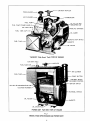
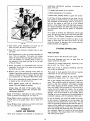
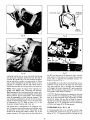
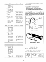
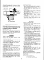
Model VH4D
3-1/4" Bore m 3-1/4" Stroke
107.7 cu. in. Displacement
2
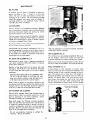
EXHAUST MUFFLER
P RE-CLEANER
AIR CLEANER
CARBURETOR
FUEL PUMP
OIL FILLER AND
BREATHER CAP
FUEL PUMP PRIMER HANDLE
AIR VENT HOLE
GASOLINE STRAINER
FUEL TANK CAP-----~
OIL SABER
~AGNETOSTOP SWITCH
MAGNETO
OIL FILTER
TAKE.OFF (Side
Mount Tank) VIEW OF ENGINE
AIR VENT HOLE
MUFFLER
FUEL
TANK CAP ~
AIR CLEANER
FUEL TANK
CHOKE BUTTON
VARIABLE SPEED
GOVERNORCONTROL
IGNITION SWITCH
OIL FILLER AND BREATHER
CYLINDER NUMBERS
FLYWHEEL SHROUD
OIL FILTER
E TO
OIL DRAIN PLUG
POWER UNIT
FAN END VIEW OF ENGINE
F~g.1
MODEl VH4D OPEN ENGINE AND POWER UNIT
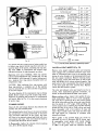
NOTE:
CYLINDERS, RINGS, PISTONS, PINS, TAPPETS, VALVES,
CAMSHAFT, BEARINGS AND ETC. ARE LUBRICATED BY
THE OIL SPRAY OR MIST THROWN OFF THE CONNECTING RODS AND CRANKSHAFT.
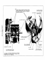
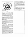
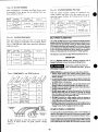
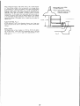
OIL
STANDARD LOCATION
OF OIL GAUGE SABER
OIL
STRAINER
OIL FILLER AND
BREATHER CAP
SPRAY NOZZLES
OPTIONAL LOCATION
OF OIL GAUGE SABER
OIL HEADER TUBE
OIL FILTER
OIL LINE TO
GOVERNOR
FULL AND LOW MARKS
ON OIL GAUGE SABER
CRANKSHAFT OIL
SLINGER
OIL PRESSURE RELIEF VALVE
SET FOR 15 POUNDS PRESSURE
WITH ENGINE AT OPERATING TEMPERATURE, OIL PRESSURE
IN HEADER WILL BE APPROXIMATELY 5 POUNDS. AN OIL
PRESSURE GAUGE IS NOT REQUIRED.
OIL
OIL
PUMP
STRAINER
SCREEN
DRAIN PLUG
OIL RETURN FROM
FILTER INTO CRANKCASE
GENERAL INFORMATION
and
DESIGN
HORSEPOWER
R.P.M.
1400
17.2
Wisconsinengines are of the four cycle type, in which each
of the four operations of intake, compression, expansion
andexhaustrequires a complete stroke. This gives one power
stroke per cylinder for each two revolutions of the crankshaft.
1600
1800
20.0
22.5
2000
2200
24.7
26.5
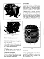
COOLING
2400
28.0
29.2
30.0
Cooling is accomplished by a flow of air, circulated
over the cylinders
and heads of the engine,
by a
combination fan-flywheel
encased in a sheet metal
shroud. The air is divided and directed by ducts and
baffle plates to insure uniform cooling of all parts.
Never operate an engine with any part of the
shroudingremoved.- this will retard air cooling.
Keepthe cylinder and head fins free from dirt and
chaff. Improper circulation
of cooling air will
cause engine to overheat.
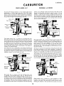
CARBURETOR
The proper combusUble mixture of gasoline
and air
is furnished by a balanced carburetor,
giving correct
fuel to air ratios for all speeds and loads.
IGNITION
SYSTEM
The spark for ignition of the fuel mixture is furnished
by a high tension magneto driven off the timing gears
at crankshaft
speed..The magneto distributor
rotor
turns at half-engine speed. The magneto is fitted with
an impulse coupling, which makes possible a powerful spark for easy starting.
Also, the impulse coupling
automatically retards the spark for starting,
thus eliminating possible kick back from engine while cranking.
Battery ignition (12 volt); distributor
is furnished
place of magneto on engines equipped with flywheel
alternator or belt driven generator. See Pages 12-15.
LUBRICATION SYSTEM(Fig.
2600
2800
the power take-off end of the crankshaft. The flywheel
end of the engine is designated the front end, and the
power take-off end, the rear end of the engine.
HORSEPOWER
Horsepower specified in the accompanying chart is for
an atmospheric temperature of 60° Fahrenheit at sea
level and at a Barometric pressure of 29.92 inches of
mercury.
For each inch lower the Barometric pressure drops,
there will be a loss in horsepower of 31/~%.
For each 10° temperature rise there will be a reduction in horsepower of 1%.
For each 1000 ft. altitude above sea level
be a reduction in horsepower of 3~/2%.
there
will
The friction
in new engines cannot be reduced to the
ultimate minimum during the regular block test, but
engines are guaranteed to develop at least 85 per cent
of maximum power when shipped from the factory.
The
power will increase as friction
is reduced during the
first few days of operation.
The engine will deyelop
at least 95% of maximum horsepower when friction
is
reduced to a minimum.
For continuous operation,
shown as a safety factor.
allow
20% of horsepower
3)
A gear type pump supplies oil to four nozzles which
direct oil streams against fins on the connecting rod
caps. Part of the oil enters the rod bearing through
holes in the rods, and the balance of the oil forms a
spray or mist which lubricates
the cylinder walls and
other internal parts of the engine. An external oil line
from the oil header tube in the crankcase lubricates
the governor and gear train.
GOVERNOR
A governor of the centrifugal
flyweight type maintains
the engine speed by varying the throttle
opening to
suit the load imposed upon the engine. These engines
are equipped with either
a fixed speed governor, a
variable speedcontrol to regulate the governed speed
of the engine, or an idle control.
ROTATION
The rotation
of the crankshaft
is clockwise when
viewing the flywheel or cranking end of the engine.
This gives counter-clockwise
rotation when viewing
STARTING
and
OPERATING
INSTRUCTIONS
Engines that are enclosed in a sheet metal house, as
shown in bottom view of Fig. 1, are called
power
units. Others are furnished without a house, as shown
in top view of Fig. 1, and are called open engines.
On engines with a house, the side doors must
always be removedwhenoperating.
This is necessary for circulating
cooling the engine.
sufficient
air
for
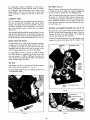
LUBRICATION
Before starting
a new engine, fill the oil base with
good "gasoline engine" oil, as specified in the =Grade
of Oil" chart. Fill through the breather tube shown in
Fig. 3, with 4 quarts of oil.
For run-in of new engines, use same oil
mendedin Grade of Oil Chart.
as recom-
After the engine has been run for a short time, the oil
lines and oil filter will have been filled with oil. Shut
GRADE OF OIL
SEASONOR TEMPERATURE
GRADEOF OIL
Spring, Summer
or Fall
+ 120°F to + 40°F
Winter
+ 40°F to + 15°F
+ 15°F to 0°F
BelowZero
Use Oils classified
SAE30
SAE 20-20W
SAE 10w
SAE 5W-20
as Service SE, SF, SGor CC
Newengine
4 Qts.
Crankcase Oil andfilter change
4 Qts.
Capacity
Less- filter or filter change 3~ Qts.
off the engine and check the oil level by means of
dip stick (oil gauge saber). If necessary, add enough
oil to bring level up to the full mark. The standard dip
stick location is below the oil filler-breather
tube, but
can be located on starting motor side upon request.
Use only high-grade highly refined oils, corresponding
in body to the S. A. E. (Society of Automotive Engineers)
Viscosity
Numbers listed
in Grade of Oil
Chart.
SERVICE CLASSIFICATION OF OIL
In addition to the S.A.E. Viscosity grades, oils are also
classified according to severity of engine service. Use oils
classified by the Americal Petroleum Institute as Serviae
SE, SFor SG. These types ofoil are for engines performing
under unfavorable or severe operating conditions such as:
high speeds, constant starting and stopping, operating in
extreme high or low temperatures and excessive idling.
Follow summer recommendations
housed in warm building.
in winter if engine is
Checkoil level every 8 hours of operation.
The old oil should be drained and fresh oil
after every 50 hours of operation.
added
tank is approximately 6 gallons.
Some of the poorer
grades of gasoline contain gum which will deposit on
valve stems, piston rings, and in the various small
passages in the carburetor,
causing serious trouble
in operating and in fact might prevent the engine from
operating at all.
Use only reputable,
well
known
brands
of
Unleaded
The gasoline should have an octane rating of at least 87.
Low octane gasoline will cause the engine to detonate, or
knock, and if operation is continued under this condition,
cylinders will score, valves will burn, pistons and bearings
will be damaged, etc.
Be sure that air vent in tank cap is not plugged with dirt, as
this would prevent fuel from flowing to the carburetor.
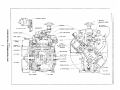
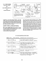
FUEL PUMPand PRIMING (Fig.
4)
The diaghragm type fuel pump, furnished on engines
with side mount or underslung fuel tanks, is actuated
by an eccentric
on the camshaft, as illustrated
in
cross section of engine, Fig. 2.
Hand Primer for hand crank engine is an accessory
furnished only upon request, and is a necessary function when starting a new engine for the first time, or
when engine has been out of operation for a period of
time. Gravity feed and electric
start engines do not
require hand priming.
When priming, a distinct
resistance
of the fuel pump
diaghragm should be felt when moving the hand lever
up and down. If this does not occur, the engine should
be turned over one revolution
so that the fuel pump
drive cam will be rotated from its upper position which
prevents movement of the pump rocker arm.
Assuming the gasoline strainer is empty, approximately 25 strokes of the primer lever are required to fill
the bowl. See Fig. 4. After strainer bowl is full, an
addiUonal 5 to 10 strokes are required to fill the
carburetor
bowl. When carburetor
is full the hand
primer lever will move more easily.
To drain oil, remove drain plug illustrated
in Fig. 3.
Oil should be drained while engine is hot, as it will
then flow more freely.
OIL PRESSURE
At engine operating temperature, the oil pressure will
be about 4 to 5 pounds per square inch, and due to
this low pressure system, an oil pressure gauge is
not required.
When the engine is cold the pressure
will be higher, and a relief valye is fitted to the oil
pump so that under these conditions
the maximum
pressure will be limited to 15 pounds.
FUEL
These engines can be furnished with either a gravity
feed tank mounted above the carburetor fuel level, a
side mount tank, or tank mounted below the engine.
In the latter two cases, a fuel pump is furnished.
The fuel tank should be filled
with a good quality
gasoline free from dirt and water. The capacity of the
gasoline.
Fig. 4
IGNITION SWITCH
Magnetoignition is standard on these engines, with a lever
typeswitch
onthesideofthemagneto,
which
isalways
inthe
onorrunning
position,
except
whendepressed
forstopping
theengine.
SeetopviewofFig.].
Onpower unit engines, a push button ignition switch is
mountedon the outside of the housepanel at the flywheelend.
See bottomview of Fig. 1. Whenstarting engine, the ignition
switch button is pulled out. To stop, pushin. This will apply
to both magneto
and batteryignition systems.
Racingan engineby disconnecting
the governor,or by
doinganythingto interfere with the governorcontrolled engine speed, is extremelydangerous.
The govemoris provided as a meansfor controlling the engine speed to suit the
load applied, and also as a safety measureto guard against
excessive speeds, whichmeasureto guard against excessive
speeds, whichnot only overstrain all workingparts, but which
whichnot only overstrain all workingparts, but whichmight
causewreckingof the engineand possibleinjury to bystanders.
STARTING
/~
a safe distance from moving
WARNING Maintain
parts of equipment.Knowhowto stop
All parts of the engine are designed to safely withstandany
speeds which might normally be required, but it must be
remembered
that the stresses set up in rotating parts, increase
with the square of the speed. That meansthat if the speedis
doubledthe stressed will be quadrupled;and if the speedsare
trebled, the stresses will be nine times as great.
the engine quickly in case of emergency.
/~
WARNING
Donot operateenginein a closedbuilding unlessit is properlyventilated.
STARTING PROCEDURE
1.
Checkcrankcaseoil level and gasoline supply. Openfuel
shut-off valve in fuel strainer or tank.
2.
Disengageclutch, if furnished.
minutesof runningat moderate
speed.Racingan engineor
gunningit, to hurry the warm-up
period, is verydestructive
to the polishedwearing
surfaceson pistons,rings, cylinders,
bearings, etc., as the properoil film on these varioussurfaces
cannot be established until the oil has warmedup and become
sufficiently fluid. This is especially importantonnewengines
and in cool weather.
Strict adherence
to the aboveinstructions cannotbe
too strongly urged, andgreatly increasedenginelife
will result as a rewardfor theseeasily appliedrecommendations.
STOPPING ENGINE
Pull variable speedcontrol ’/"handle out about half-way
andlock in place. Witha twospeedcontrol, start in full
load position - idle after enginestarts.
4.
Magnetoignition engines, less house, have a lever type stop
switch on the side of the magneto.Onthese, to etop engine,
depresslever and holddown
until enginestops.
Close choke by pulling choke button to extreme out
position.
5.
Pull out ignition switch button if tag reads To StopPush
In’, or, turn ignition switchto ’on’position.
6.
Depressstarter switchto start engine, or, turn switchto
’start’ position.
Powerunits and battery ignition engines,are furnishedwithan
ignition switch, "To Stop PushIn".
If the engine has beenrunninghard and is hot, do not stop it
abruptly fromfull load, but removethe load and allow engine
to run idle at 1000to 1200R.P.M.for three to five minutes.
This will reduce the internal temperatureof the engine much
faster, minimizevalve warping, and of course the external
temperature,including the manifoldand carburetor will also
reducefaster, due to air circulation fromthe flywheel.
IMPORTANT
Donot crank engine for morethan 30 seconds at a time
if engine fails to start, wait about 2 minutes between
crankingperiods to prevent starter fromover-heating.
Twomaintroubles resulting fromabruptly shutting off a hot
engine are vaporlockanddieaeling. Vaporlock will prevent
the flowof fuel in the fuel lines andcarburetorpassages,which
will result in hard starting. This can be overcome
by choking
the engine whencranking or waiting until the engine has
cooled off sufficiently to overcomethe vapor lock.
After engine starts, push chokebutton in gradually as
required for smoothrunning. Chokemust be completely
open (button in ) whenengine is warmedup.
Dieseling,is caused by the carbon deposits in the cylinder
headbeing heated up to such an extent that they continue to
fire the engine and keep it running after the ignition has
been shut off. By idling the engine, as previously mentioned, the carbondeposits cool off, break up and will blow
out through the exhaust.
If flooding should occur, open chokefully by pushing choke
button in and continue cranking. Less chokingis necessaryin
warmweather or whenengine is warm,than whencold.
WARM-UP PERIOD
The engine should be allowed to warmup to operating
temperaturebefore load is applied. This requires only a few
9
Fig. 8
Fig. 7
is in good condition; otherwise use a new gasket. See
Fig. 7, which shows the strainer mounted to the fuel
tank of a power unit. On open engines, the strainer is
mounted to the inlet of the fuel pump.
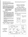
MEASURE BREAKER
POINT
GAP
WHEN~
OPEN. ADJUST TO
.015 INCH
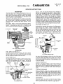
CARBURETOR ADJUSTMENT
BREAKER ARM-
The main metering jet in the carburetor is of the fixed type, that is, it requires no adjustment. The idle
needle should be adjusted for best low speed operation, while carburetor throttle is closed by hand. For
illustrations
and more information,
see Carburetor
Manufacturer’s
Instruction
Bulletin in the back of
this manual.
LOCKING
MAGNETO BREAKER POINT
CONTACT
ADJUSTING
SCREWS
PLATE~
SLOT
OPENENDVIEW OF FAIRBANKS-MORSE
MAGNETO
Fig. 9
so that it will seal properly. Do not force cover screws
too tightly otherwise cover may crack. For further information,
see Fairbanks-Morse
or Wico Magneto
Maintenance Manual in the back of this manual.
ADJUSTMENT
Magnetos are properly adjusted before leaving factory. The breeker points on the Fairbanks-Morse magneto and on the Wico magneto should be .0|5" at full
separation.
If the spark becomes weak after continued
operation,
it may be necessary
to readjust
these
points. To do this first
remove the end cover on the
magneto. The crankshaft should then be rotated with
the starting crank, (this also rotates the magneto),
until the breaker points are wide open. The opening
or gap should then be measured with a feeler gauge
as shown in Fig. 8 and if necessary reset. To readjust
points, first loosen the locking screws on the contact
plate enough so that the plate can be moved. Insert
the end of a small screw driver into the adiusting slot
at the bottom of the contact plate and open or close
the contacts
by moving the plate until the proper
opening is obtained. See Fig. 9. After tightening the
locking screws, recheck breaker point gap to make
sure it has not changed. If it is found that the breaker
points have become rough, they should be smoothed
with a breaker point file before the preceding adjustments are made. Replace magneto end cover carefully
MAGNETO IGNITION
SPARK
If difficulty
is experienced in starting the engine or
if engine misses firing, the strength of the ignition
spark may be tested by disconnecting the No. 1 ignition cable from the spark plug and holding the terminal about 1/8 inch away from the air shroud or any
other conveniently located metal part of the engine.
If the ignition cables have a molded rubber insulated
spark plug terminal at the end, as illustrated
in Fig.
lO, wedge a piece of bare wire up into the terminal
and let one end of the wire extend out. Turn the engine over slowly by the starting
crank two complete
revolutions
and watch for a strong spark discharge,
which should occur during the cycle at the instant the
impulse coupling on the magneto snaps. Repeat this
check with each of the other ignition cables. If there
is a weak spark, or none at all, check breaker point
opening as mentioned in preceding paragraph under
11
Next, remove the spark plug from No. 1 cylinder and
slowly turn the flywheel clockwise, at the same time
holding a finger over the spark plug hole, so that the
compression stroke can be determined from the air
blowing out of the hole.
The flywheel is marked with the letters ’DC’ near one
of the air circulating
vanes. This vane is further
identified by an ’X’ mark ~cast on the end.See Fig. 11.
When the air blows out o,f the No. 1 spark plug hole,
continue turning the crank until the edge of the marked vane on flywheel is on line with the mark on the
~ertical centerline of the shroud as shown on Fig. 11.
Leave flywheel in this position.
At this point the
~e),way for mounting the flywheel is also on top.
Reassemble spark plug.
Next, remove the inspection
hole plug from the magneto timing opening, located in the gear cover as
shown in Fig. 10.
Assuming that the magneto has been removed from
the engine, the following procedure should be followed before remounting.
HOLE PLUG
The Number 1 cylinder firing position of the magneto
must be determined. Insert the ignition cable into the
No. 1 tower terminal of the magneto end cap and hold
the spark plug terminal at the other end, about 1/8"
away from the magneto body. Turn the magneto gear
in a clockwise rotation, tripping the impulse coupling,
until the No. 1 terminal sparks, then hold the gear in
this position. Mount the magneto to the engine, meshing the gears so that when the magneto is in place,
the gear tooth marked with an ’X’ will be visible
through the lower half of the inspection hole in the
gear cover, as shown in Timing Diagram, Fig. 11.
Tighten the nut and capscrew for mounting the magneto to the gear cover, making sure the magneto
flange gasket is in place.
Fig. lO
=Magneto Breaker Point Adjustment’. If this does not
remedy the trouble, it may be necessary to install
a
new condenser.
See Magneto Manufacturer’s
Maintenance Instructions
in back of this manual.
FIRING
ORDER
’The firing order of the cylinders is 1-3-4-2,and the
magneto and battery type distributor rotate at one-half
engine speed, as is the case with conventional
=in
line" engines. The intervals between the firing of the
cylinders is 180 o. No. 1 cylinder is the one nearest to
the flywheel in the left bank of cylinders, when viewed from the flywheel end of the engine. No. 3 cylinder
is the other cylinder in this bank. No. 2 cylinder is
the one nearest to the flywheel in the right bank of
cylinders and No. 4is the other cylinder in this bank.
The cylinders
are numbered from 1 to 4 on the air
shroud near the spark plugs. The flywheel end of the
engine is designated the front and the power take-off
end, the rear of the engine.
The No. 1 terminal is identified
on the magneto cap.
The terminals follow the proper firing order of 1-3-4-2
in a clockwise direction
viewing the cap end. The
leads from the magneto should be connected to spark
plugs of corresponding numbers.
No. 1 cylinder is the cylinder nearest the fan-flywheel
of the engine in the left bank and No. 3 cylinder is the
other cylinder in that bank. No. 2 cylinder is across
the engine from No. 1 and No. 4 is across from No. 3.
When the magneto is properly timed the impulse coupling will snap when the ’DC’ and ’X’ marked vane of
the flywheel, line up with the mark on the flywheel
shroud which indicate the centerline of the No. 1 and
3 cylinders.
This can be checked by turning crankshaft over slowly by means of a hand crank. The impulse will also snap every 180° of flywheel rotation
thereafter.
MAGN ETa TIMING
The proper spark advance is 23 ° . To ,check timing
with a neon light, the running spark hdvance is indicated by a 3/8 inch slotted hole in the rim of the air
intake screen, 68° left of the flywheel shroud vertical centerline,
marked VH, or if screen is removed,
time to the lower half of the 1/4 inch elongated hole
on the face of flywheel shroud 23° below the centerline of No. 1 and No. 3 cylinders as illustrated
in
Fig. 11. The end of the ’X’ marked vane should be
whitened with chalk or paint for this operation.
DISTRIBUTOR - BATTERY IGNITION
On engines equipped with Flywheel Alternator or belt driven
alternator, battery ignition is used in place of magnetoignition. The distributor is of the automatic advance type, and
rotor turns at one-half engine speed in a counterclockwise
direction.
To Time hiagneto to Engine: Remove air intake
screen to expose timing ,marks on both flywheel and
shroud. See Magneto Timing Diagram, Fig. 11.
12
VERTICAL CENTERLINE
MARK
ON SHROUD FOR
TIMING MAGNETO.
No. 1 TERMINAL INDICATED ON
MAGNETO END CAP AS SHOWN.
OTHER TERMINALS FOLLOW FIRING ORDER IN CLOCKWISE ROTATION.
EDGE OF VANE IN LINE WITH
MARK ON SHROUD WHEN TIMING MAGNETO.
’X’ MARKED VANE ON
FLYWHEEL
NO 9--
NO
NO 3
~
4
1 CRANKPtN
0
CRANKSHAFT
GEAR
RUNNING SPARK ADVANCE
FOR CHECKING WITH NEON
LIGHT.
~N~_3 CR~,NKPIM
~MARKED
GEAR
TOOTH,
~THUS
~
THROUGH OPENING,
FLYWHEEL
IS LOCATED
DICATED
ABOVE.
VISIBLE
WI EN
AS
MAGNETO
FLYWHEEL KEYWAY
ON TOP
GEAR
2 CRANKPtN
Fig.
11,
MAGNETOTIMING DIAGRAM
removing screen. To make a stationary checkof the
timing-removethe screen over the flywheel air intake
opening by taking out the screws holding the screen in
The dislributor is mountedto an adapter attached to the gear
cover, or TopMounted- attached to the governorhousing.
~
d~
RECTIFIER
MODULE
The spark advance for normal speeds is 23° , the same
as for magneto ignition. Engine must be running at
2000 R.P.M. or over whenadjusting spark advance.
=~_z/
~
~
~--~
12 VOLT
REGULATOR
~ULE
~
ELECTRICAL WIRING CIRCUITS
NOTE:Beginning with engine serial No. 3987113, the
standard
wiringcircuits for all 12 voltelectrical equipment
is
negative ground polarity, in place of the previously
furnished positive ground. All 6 volt systems remain
positive ground.
AUTO.TIC
~u~
~_ ¯
~
I
~~
~
~.
’
SPARKPLUGS,
The Flywheel Alternator circuit illustrated in Fig. 12
always was and is a negative groundsystem. It replaces
the previously furnished gear driven generator which
was available both negative and positive ground.
I
~
~,C~nne~i~,,
~ConnB~ions
or LJg Is’~
h ’ -al chargesideo1 ammeter
(negative
terminal).
~ Conne~ E~uipment
~Jenoids Rer~
A
r .... "~.~" .......
START
,, SWITCH
,,(optionol)
SOLENOID
SWITCH
(optional)
Wiringdiagramand service parts information for obsolete gear driven type generator can be obtained by
writing Wisconsin Motors, LLC,Memphis,TN38133.
DISTRIBUTOR
DRIVE
Ht-TEMP SWITCH ~
(optional)
STARTING MOTOR
DISTRIBUTOR TIMING
A slotted opening has been added to the rim of the
flywheel screen to check runningsl~rk advan¢~without
Fig. 12, WIRINGDIAGRAM,
25ampFlywheelAlternator andBattery Ignition
13
NEON LAMP TIMING
SETGAP
The engine should be timed to the 23° advanced
position at not less than 2000 R.P.M.
The timing should be checked with a neon lamp connected
in series with No.1 spark plug. Chalkor paint the end of the
"X" marked vane on Ihe flywheel, white. Then with the
engine operating at 2000 R.P.M. or over, allow the flash
from the neon lamp to illuminate the whitened vane. At the
time of the flash, the leading edge of the vane should line
up with the lower half of the running spark advance
timinghole on the flywheel shroud, see Fig. 13. If it does
not, the advance arm clamp screw should be loosened,
and the distributor body turned slightly clockwise or
counterclockwise,as required, until the white flywheelvane
matchesup with the lower half of the advancetiming hole.
Be sure advance arm clamp screw is then carefully
tightened. If the engine is running below2000R.P.M.when
timing, the automaticadvancein the distributor will not be
fully advancedand the inaccurate timing maycause serious
damageto the engine whenoperating at high speeds. Mount
flywheel screen if removed- use slotted opening without
removingscreen for running spark advancecheck only.
Fig.16
SPARKPLUGS, Fig. 16
Incorrect gap, fouled or worn spark plug electrodes,
will have an adverse affect on engine operation. Removespark plugs periodically, clean, regap or replace
if necessary. Thread size is 18 ram.
Sparkplug gap- 0.030 of an inch.
Replacement plugs must be of the correct heat range,
like Champion No. D-16J, AC No. C86 commercial.
Tighten spark plugs, 25 to 30 {oat pounds torque.
HIGH TEMPERATURESAFETY SWITCH
POINT TYPE IGNITION
DISTRIBUTOR
As a safety precaution against overheating, engines
can be equipped with a high temperature switch
mountedto the cylinder head at the No. 4 spark plug.
The distributor breaker point gap should be .018 to .022
inches. To readjust breaker point gap, turn engine over by
meansof the starting crank until the distributor breaker arm
rubbingblock is on a high point of the cam. Loosen the
stationary contact locknut and screw fixed contact, in or
out, until correct gap is obtained. Tighten locknut and recheck gap.
Whencylinder head temperature becomes critically
high, the safety switch will automatically stop the engine by shorting out the ignition system. A waiting
period of about 10 minutes will be required before the
switch has cooled off sufficiently to re-start the engine. An overheated engine will score the cylinder
walls, burn out connecting rod and crankshaft bearings, also warp pistons and valves. The cause of the
overheating condition will have to be remedied before
the engine is re-started. See EngineOverheatsparagraph in Troubles, Causes and Remedies section.
Service Kit is available - see parts list section.
SOLID STATE IGNITION DISTRIBUTORS
ManyWisconsinengines are nowbeing equipped with a solid
state ignition distributor. Detailedtroubleshooting,repair and
parts information can be found in the rear section of this
manual.
KEEP ENGINE CLEAN -PREVENT OVERHEATING
(Agricultural andIndustrial Engines)
This engine is cooled by blasts of air which must be
allowed to circulate all around the cylinders and cylinder heads to properly cool the engine and thereby
keep it in good running condition. If dust, dirt or
chaff is allowedto collect in the cylinder shrouding
or in the V between
the cylinders, it will retard the
flow of air and cause the engine to overheat. Keep
flywheel screenand rotating screen clean, so as not
to restrict the intake of cooling air.
CHARGING SYSTEM
Enginescanbe equipped
with a 10 amp,25 amp,or 30 amp
flywheelalternatorsystem
or a 37 ampbelt drivenalterna.
tor. Instructionsare locatedin the rear of this manual.
RESTORING COMPRESSION
In a newengine or one whichhas beenout of operationfor
sometime, oil mayhave drained off the elyinders so that
compressionwill be weak, causing difficulty in starting. To
remedythis condition, removethe spark plugsandpourabout
a fluid ounceof crankcaseoil through
the spark plughole into
each cylinder. Turn engine over several times with the hand
crankto distribute oil over the cylinder wails. Assemble
spark
plugs and compressionshould be satisfactory.
With reference to Fig. 17; follow the cleaning and
maintenance instructions
pointed out, to obtain
trouble fre~ and satisfactory engine performance.
1. Removethese covers frequently and clean out all
dust, dirt and chaff. Be sure to replace covers.
15
maintaining satisfactory
gines. They are:
operation
of gasoline
en-
1. A proper fuel mixture in the cylinder.
2. 6ood compression in the cylinder.
3. 6ood spark, properly timed, to ignite
the mixture.
If all three of these conditions do not exist, the engine cannot be started.
There are other factors which
will contribute to hard starting; such as, too heavy a
load for the engine to turn over at a low starting
speed, a long exhaust pipe with high back pressure,
etc. These conditions may affect the starting,
but do
not necessarily
mean that the engine is improperly
adjusted.
As a guide to locating any difficulties
which might
arise, the following causes are listed under the three
headings: Fuel Mixture, Compression, and Ignition.
In each case, the causes of trouble are given in the
order in which they are most apt to occur. In many
cases the remedy is apparent,
and in such cases no
further remedies are suggested.
Fig. 17
2. Open these covers frequently
and clean
dust and chaff. Be sure to close covers.
out all
3. Keep this
and chaff.
of dust
space
between
cylinders
free
STARTINGDIFFICULTIES
FUEL MIXTURE
on this air cleaner regarding its
4. Read instructions
care. This is important.
The entire air cleaner
should be removed from the engine at least once a
year, and washed in a cleaning fluid to clean out
dirt gathered in the back fire trap in the top part
of the air cleaner.
No fuel in tank or fuel shut-off
Fuel pump diaphragm worn out,
supply carburetor with fuel.
Water, dirt, or gum in gasoline
flow of fuel to carburetor.
cartridge every other oil
6. Replace this oil filter
change. If operating conditions are extremely dusty
replace cartridge
every oil change. Be sure that
your replacement is a Wisconsin Micro-Fine filter.
Carburetor
especially
Always keep all parts of the engine clean.
This will prolong engine life, and give more
satisfactory operation.
Every 4 to 8 hours, depending on dust conditions,
check air cleaner and change oil. See Page lO.
Every 8 hours check crankcase oil level, Keep filled
to full mark on oil gauge sabre, but no more. See
Fig. 3.
with free
flooded,
caused by too much choking
if engine is hot. See ’Choke’, Page 9.
If, due to flooding, too much fuel should have entered the cylinder in attempting to start the engine, the
mixture will most likely be too rich to burn. In that
case, the spark plugs should be removed from the cylinders and the engine then turned over .several times
with the starting
crank, so the rich mixture will be
blown out through the spark plug holes. The choke on
the carburetor
should of course be left open during
this procedure.
The plugs should then be replaced
and starting tried again.
with fresh
TROUBLES
CAUSES
ANDREI~EDIES
to starting
interfering
if en-
Dirt or gum holding float needle valve in carburetor
open. This condition would be indicated if fuel continues to drip from carburetor
with engine standing
idle. Often tapping the float chamber of the carburetor very lightly with the handle of a screw driver or
similar tool will remedy this trouble. Do not strike
carburetor with any metal tools, it may cause serious
damage. Also if the mixture in the cyhnder, due to
flooding, is too rich, starting may be accomplished by
continued cranking, with the carburetor choke open.
Never operate engine with air shrouding removed.This will retard air cooling.
are essential
especially
Poor grade or stale gasoline that will not vaporize
sufficiently to form the proper fuel mixture.
7. Do not allow shrouding to become damaged or badly dented as this will retard air flow.
Three prime requisites
so pump does not
Carburetor not choked sufficiently,
gine is cold. See ’Choke’, Page 9.
5. Empty pre-cleaner
of accumulated dust and dirt
frequently. Do not use oil or water in pre-cleaner,
this must be kept dry.
Every 50 hours drain crankcase and refill
oil. See Lubrication, Pages 6 and 7.
valve closed.
and
16
To test for clogged fuel line, loosen fuel line nut at
carburetor slightly.
If line is open, fuel should drip
out at loosened nut.
Weak spark. See ’Magneto Ignition Spark’,
or ’Distributor-Battery
Ignition’, Page 12.
COMPRESSION
Magneto or distributor
Loose connections
at ignition
cable.
breaker points pitted
Poor compression.
See ’Compression’,
Page 17.
ENGINE SURGES OR GALLOPS
Carburetor flooding.
Governor spring hooked into wrong hole in lever. See
’Governor Ad/ustment’, Page 24. Governor rod incorrectly adjusted. See ’Governor/td/ustment’,
Page 24.
Cylinder dry due to engine having been out of use for sometime.
See "Restoring Compression’, Page 15.
Loose spark plugs or broken spark plug. In this case a hissing
noise will be heard when cranking engine, due to escaping gas
mixture on compression stroke.
ENGINE STOPS
Damagedcylinder head gasket or loose cylinder head. This will
likewise cause hissing noise on compression stroke.
Water, dirt or gum in gasoline.
Fuel tank empty.
Gasoline vaporized in fuel lines due to excessive
heat around engine (Vapor Lock). See "Stopping Engine’, Page 9.
Valve stuck open due to carbon or gumon valve stem. To clean
valve stems, see ’Valw’.s’, Page22.
Vapor lock in fuel lines or carburetor due to using
winter gas (too volatile) in hot weather.
clearance under valve
Air vent hole in fuel tank cap plugged. Engine scored
or stuck due to lack of oil.
Piston rings stuck in piston due to carbon accumulation. If rings
are stuck very fight, this will necessitate removing piston and
connecting rod assembly and cleaning parts. See "Piston and
Connecting Rod’ Page 21.
Ignition
troubles.
See ’Ignition’,
Page 17.
ENGINE OVERHEATS
Scored cylinders. This will require reboring of the cylinders and
fitting with new pistons and rings. If scored too severely, an
entirely new cylinder block may be necessary.
Crankcase oil supply low. Replenish
immediately.
Ignition spark timed wrong. See "Magneto Timing’,
Page 12, or "Distributor-Battery
Ignition’,
Page 12.
IGNITION
Low grade of gasoline.
See ’Magneto Ignition Spark’, Page ll or ’DistributorBattery Ignition’,
Page 12: No spark may also be attributed to the following:
Engine overloaded.
Ignition
plugs.
Part of air shroud removed from engine.
cable
Restricted
from magneto or spark
cooling air circulation.
Dirt between cooling fins on cylinder
Broken ignition
Ignition
disconnected
cables,
causing short circuits.
Engine operated in confined
is continually
recirculated,
too hot.
cables wet or soaked.
Spark plug insulators
broken.
Dirty or incorrect
Spark plug point gap wrong. See Page 15.
Restricted
on spark plug electrodes.
Magneto or distributor
breaker points pitted
Magneto or distributor
breaker arm sticking.
Magneto or distributor
condenser leaking
grade of crankcase oil.
exhaust.
ENGINE KNOCKS
Poor grade of gasoline
’Fuel’, Page 8.
Page 12,
Engine operating
ENGINE MISSES
Worn and leaking ignition
cables.
or of low octane rating.
in cylinder
head.
Spark advanced too far. See "Magneto Timing’,
12, or "Distributor-Battery
Ignition’, Page 12.
17
See
under heavy load at low speed.
Carbon or lead deposits
See Page 15.
space where cooling air
consequently becoming
Engine operated while detonating due to low octane
gasoline or heavy load at low speed.
or fused.
or grounded.
Spark timing wrong. See ’Magneto Timing’,
or "Distributor-Battery
Ignition’, Page 12.
Spark plug gap incorrect.
or head.
Carbon in engine.
Spark plugs wet or dirty.
Condensation
or worn.
Water in gasoline.
Compression check with a commercial compression test gauge
can show whether or not an engine has faulty compression.. We
do not consider it practical to publish a PSI compressionfigure
because of the variables involved: engine condition, methodof
testing, and RPMof test. Our recommendationis that whatever
gauge test is performed, a 10%variance betweencylinders would
indicate leaking rings, leaking valves or any of the following:
Valve tappets adjusted with insufficient
stems. See "Valve Tappets’, Page 23.
Page l l,
Page
possible,
totaling
applied.
Loose or burnt out connecting rod bearing.
Engine overheated
heading.
due to causes
under
previous
ACCESSORIES
Worn or loose piston pin.
ENGINE BACKFIRES
The air cleaner, oil filter,
magneto, and if an electric
starter
and generator are used, these should be removed first.
THROUGH CARBURETOR
Water or dirt in gasoline.
Remove clutch or clutch reduction unit if engine is
equipped with either of these accessories.
Engine cold.
Poor grade of gasoline.
Sticky inlet
valves.
See ’Valves’,
SHEET METAL HOUSE
Page 22.
On power units, remove the muffler and canopy first.
Disconnect air cleaner, choke, governor control and
instrument wires at the front house panel. The front
panel can be removed as part of the flywheel shroud,
as explained
in the following paragraphs
of disassembly.
Overheated valves.
Spark plugs too hot. See ’Spark Plug’, Page 15.
Hot carbon particles
operate the engine at light loads for a period
about eight hours, before maximumload is
in engine.
DISASSEMBLY AND REASSEMBLY
OF VH4D ENGINE
FLYWHEEL
After the flywheel screen has been removed, drive
out the starting
crank pin in the crankshaft and remove the flywheel nut and washer.
Engine re, pairs should be made only by a mechanic
who has had experience in such work. When disassembling the engine, it is advisable to have several boxes
available so that parts belonging to certain groups
can be kept together, such as, for instance, the cylinder head screws, etc. Capscrews of various lengths
are used in the engine, therefore great care must be
exercised in reassembly so the right screw will be
used in the various places,
otherwise
damage may
result.
The flywheel is mounted to a taper on the crankshaft.
Take a firm hold on the flywheel fins, pull outward
and at the same time strike the end of the crankshaft
with a babbitt
hammer, see Fig. 18. The flywheel
will slide off the taper of the crankshaft. Do not use
a hard hammer as it may ruin the crankshaft and bearings. When reassembling
the flywheel, be sure the
Woodruff key is in position on the shaft and that the
keyway in the flywheel is lined up accurately
with
the key.
Tighten the capscrews and nuts of the manifolds,
cylinder heads, gear cover, oil pan, connecting rods,
cylinder
blocks, main bearing plate and the spark
plugs to the specified torque readings indicated in
the following paragraphs of reassembly.
AIR SHROUDING
To disassemble air shrouding, refer to Fig. 19. First
remove cylinder
head covers and the screws mount-
While the engine is partly or fully dismantled, all of
the parts should be thoroughly cleaned. Remove all
accumulated dirt between the fins.
If it is desired to disassemble the engine, the following order should be substantially
adhered to. As disassembly progresses,
the order may be altered somewhat if desired, as will be self-evident
to the mechanic. Reassembly of the engine should be made in
the reverse order.
TESTING
REBUILT
ENGINE
Proper break-in will lead to trouble-free operation and
increased engine life. The factory test given to a new
engine is not sufficient to establish the polished bearing
surfaces which are so necessary for good performance
and long engine life. There is no quick way to force the
establishment of good bearing surfaces, and these can
only be obtained by running a new engine carefully and
under reduced speeds and loads for a short period of
time. Run the engine for a half hour without load at low
idle speed (1000 to 1200 R.P.M.). The speed should
then be increased gradually, to engine operating r.p.m.
still without load, for an additional two hours. If at all
Fig. 18
18
CYLINDER
HEAD
The cylinder head must be removed if it is necessary
to regrind valves, or to work on the piston, rings or
connecting rods. All of the cylinder head screws are
plainly in view and can be easily removed. Screws of
different
lengths are used but these can be properly
reassembled
according
to the various
lengths
of
cylinder head bosses.
In reassembly; remove all carbon and lead deposits
from combustion chamber. It is recommended that new
cylinder head gaskets be used as the old gaskets will
be compressed and hard and may not seal properly.
Use a mixture of graphite and oil on the cylinder head
screws to prevent them from rusting tight against the
cylinder block. Tighten cylinder head screws to 24
ft. Ibs. torque in the sequence shown in Fig. 21.
After complete assembly and engine is run in, retorque head screws.
Fig. 19
15
14
13
21
12
1
22 ~
F ig. 20
ing the flywheel shroud to the lower cylinder shrouds
and cylinder heat deflectors,
then remove the screws
holding the flywheel shroud to gear cover.
On power units, remove the front end panel together
with flywheel
shroud. Remove the rear end panel
complete with fuel tank. Balance of shrouding can
now be readily removed.
In Reassembly; use the thin head capscrews~ for
mounting the flywheel shroud, in the two holes close
to the horizontal centerline. This is for stntor clearance on engines with flywheel alternator.
6
FUEL TANK
If a side mount fuel tank is used, disconnect
line and remove tank assembly as illustrated
Fig. 20.
7
8
F ig. 21
fuel
in
GEAR COVER
Disconnect the governor linkage and remove governor
housing and gear-flyweight
assembly from shaft in
gear cover. Take out the ten gear cover capscrews
and drive out the two dowel pins as shown in Fig. 23.
The cover can then be taken off - exposing the gear
train as illustrated in Fig. 24.
CARBURETOR AND MANIFOLD
The carburetor
and manifold can be removed as a
complete unit. In reassemhly; tighten the manifold
nuts to |8 ft. lbs. torque. Tightening beyond specifications may cause the flanges to break.
19
OIL PUMP(Fig.
In reassembly;
inspect crankshaft
oil seal and replace if necessary. Be sure that oil sling is in place
on crankshaft,
then mount gear cover using a new
flange gasket. Tap the two dowel pins in place and
mount capscrews.
Tighten screws 14 to 18 ft. Ibs.
torque.
Remove locknut and driver gear from shaft. If gear is
too tight to remove by hand, use a puller, hammering
on end of shaft to loosen gear will damage pump.
Take out slotted pipe plug from bottom of crankcase.
By means of a 5/32 inch Allen wrench, remove lockscrew from pipe plug hole. Withdraw oil pump from inside crankcase. If pump fits too tight to remove by
hand, tap front of pump housing (not shaft), with hammer and brass rod.
CAMSHAFT GEAR
If it is necessary that the camshaft gear be removed,
first pry oil sling off crankshaft, and remove thrust
plunger and spring from end of camshaft. Take out
the three capscrews and lockwashers,
and remeve
gear from camshaft using a screw driver or similar
wedge tool.
PISTONS and CONNECTINGRODS(Figs.
28, 29, 32)
By meansof a 1/2" socket wrench, loosen and remove
the hex locknuts from connecting rod bolts. Then, by
tapping the ends of the bolts lightly,
the connecting
rod cap will break free from the bolts.
The camshaft gear has offset mounting holes to provide accurate assembly for valve timing. The gear can
only be put on the correct way for matching up the timing mark with that of the crankshaft gear. See Fig. 24.
IDLER
27)
Scrape off all carbon deposits that might interfere
removal of pistons from upper end of cylinder.
GEAR AND SHAFT
A tapped hole in the side of the crankcase contains
a setscrew for locking idler shaft in place. See Fig.
25. Remove screw with a 5/32" Allen wrench. Disassemble shaft and gear from case by means of the
3/8"-16 tapped puller hole in end of idler shaft.
CAMSHAFT
GEAR
with
Turn
GOVERNOR
GEAR
In reassembly; be sure oil groove in shaft is facing
up. Drive shaft into crankcase with soft metal hammer and maintain a .003 to .004 inch clearance between idler gear and shoulder of shaft. Lock shaft in
place with the Allen set screw.
OIL PAN
TIMING
MARKS
The engine can now be inverted so that the supports
and oil pan can be removed, see Fig. 26.
In reassembly; tighten
9 foot poundstorque.
oil pan mounting screws,
SHAFT
GEAR
6 to
IDLER
GEAR
OIL PUMPGEAR
F~g.24
IDLER GEAR
GEAR PULLER
3/8"-i6
GEAR
BOLT
COVER
ALLEN
SET SCREW
LOCATEDIN CRANKCASE
Fig. 25
Fig. 23
2O
STAMPED
NUMBERS
LOCATING LUGS
SHELL
BEARING
Fig. 26
Fig. 28
MARK ON CAP
OIL SPRAY NOZZLES
Fig. 29
Fig, 27
are 90° from the axis of the piston pin hole, with the
wide section of the piston skirt toward the maximum
thrust side, or opposite the crankshaft rotation,
See
Engine Sectional, Fig. 2.
crankshaft untilpiston is at top, then push connecting
rod and piston assembly upward and out thru top of
cylinder. Be careful not to mar the crank pin by allowing the rod bolts to strike or scrape across it. Place
caps on rods immediately so that they willnot be mismatched in reassembly. Be sure that shims (used in
babbitt bearing rods), are in place before cap is put on.
In reossembly; be sure piston and connecting rod assemblies are put back into the same bore from which
they were removed. Use a suitable
ring compressor
and stagger the piston ring gaps 90° apart around the
piston. Oil the pistons, rings, wrist pins, rod bearings
and cylinder walls before assembly.
NOTE: These models of engines were originally
furnished with babbitt cast connecting rod bearings.
Shell bearing rods are now being used for current production engines, and are interchangeable with babbitt
bearing rods for service replacement. Care should be
taken in reassembly to mount bearings properly. The
cap should be assembled to the rod so that the local.
ing lug of both bearing halves are on the same side
as illustrated
in Fig. 28. Refer to chart, Fig. 32, for
clearance between bearing and crank pin.
CAUTION: Identical
numbers are stamped on the side
of the rod with its corresponding cap. These numbers
must be on the same side of the connecting rod when
mounted in engine. Be sure that oil hole in connectiag rod cap is facing toward the oii spray nozzle, as
illustrated
in Fig. 29. Install new nuts on connecting
rod bolts and torque 22 to 28 foot pounds.
The piston skirt is cam-ground to an elliptical
contour. Clearance between the piston and cylinder must
be measured at the center of the thrust face at the
bottom of the piston skirt. Refer to Chart, Fig. 32, for
proper clearance. The thrust faces on the piston skirt
PISTONRINGS (Fig’s.
30, 31, 32)
If a ring expander tool is not available, install rings
by placing the open end of ring on piston first,
as
shown in Fig. 30. Spread ring only far enough to slip
21
PISTONTO CYLINDER
AT PISTONSKIRT THRUSTFACE
.003 to .004"
PISTONRING GAP
.010 to .020"
TOP RING
PISTONRING
SIDE CLEARANCE
IN GROOVES
.002 to .004"
SCRAPER
RING
OIL RING
PISTONPIN TO
CONNECTING
RODBUSHING
.002
to .004"
.001
to .003"
=
.0004 to .0012
.0000to .0008"
tight
PISTONPIN TO PISTON
CONNECTING
RODTO
CRANKPIN- SIDE CLEARANCE
PLACEOPENENDOF
RING ON PISTON
FIRST AS SHOWN
CONNECTING
RODSHELLBEARING
TO CRANKPIN DIA. (VERTICAL)
Fig. 30
CONNECTING
RODBABBITT
BEARINGTO CRANKPIN
11"I;56 DIA. GRIND
Fig. 31
Fig. 32, PISTON,RINGANDRODCLEARANCES
CHART
over piston and into correct groove, being careful not
to distort ring. Install bottom ring first and work toward the head of the piston, installing top ring last.
The word ’TOP’ on compression
and scraper rings
indicates direction of ring placement on piston.
VALVESand SEAT INSERTS (Fig.
33)
Remove valve tappet inspection
plate and compress
valve springs with a standard automotive type valve
lifter as illustrated.
Insert a rag in the opening at the
bottom of valve chamber so the retaining locks do not
fall into engine crankcase. Remove retaining locks,
seats, springs, valves and clean these, as well as the
ports and guides, of all carbon and gum deposits. Tag
each valve so that in reassembly they willbe mounted
in the same guide they were removed from. Replace
valves that are burned or pitted.
Beginning with serial
#5538322, three ring pistons
(chrome faced compressionring, scraper ring, oil ring
and expander), with improved oil control characteristics, replaces four ring pistons furnished with two
compression rings.
CAUTION: When replacing
four ring pistons
with
three ring pistons,
a complete set of four pistons
must be used. Do not mix three and four ring pistons
in the same engine.
The inlet and exhaust valve seat inserts can be removed, when replacement
becomes necessary,
by
means of Wisconsin Motor DF-66-A insert puller.
The outer diameter of the compression ring is chrome
plated. Mount scraper ring with scraper edge down,
otherwise oil pumping and excessive oil consumption
will result. Refer to Fig. 31 for the correct placement
of piston rings.
Before grinding valves, inspect valve guides for possible replacement.
Refer to Falve Guide paragraph.
The valve face is ground at 45°to the vertical center
line of the valve stem and the valve seat insert should
also be ground at a 45° angle. After grinding,
lap
valves in place until a uniform ring will show entirely
around the face of the valve. Clean valves and wash
block thoroughly with a hot solution
of soap and
water. Wipe cylinder walls with clean lint free rags
and light engine oil, especially
if cylinders were
rebated and honed.
BLOCKS
from between the
The cylinder blocks do not have to be removed unless
the cylinder bore is scored, out-of-round, or worn oversize more than 0.005 inch. In this event, the block
will have to be removed, rebated and fitted with oversize pistons and rings. This work should be done by
an authorized Wisconsin Service Center.
In Reassembly; tighten the cylinder
nuts, 40 to 50 foot pounds torque.
.0007to .0020"
_
OIL RINGWITH
EXPANDER
Clean all dirt and foreign deposits
cylinder fins and manifold ports.
.0012to .0033"
~’~
STANDARD
~ ~’/ CRANKPIN DIMENSIONS
CHROMEFACED
COMPRESSION
RING
SCRAPER
RING
CYLINDER
.009 to .016"
Valve guides in the cylinder
block are easily replaceable
by use of Wisconsin DF-72 driver tool.
In reassembly;
mount guides with inside chamfer
down. The valve stem has a clearance
of .003
to .0054 in the guide. When the clearance
becomes
block mounting
22
the tapered roller main bearings on the crankshaft.
This end play should be .002 to .004 inch when engine is cold. There is practically
no wear in these
bearings so that no readjustment
is necessary after
proper assembly.
VALVELIFTER
When reassembling
crankshaft,
the timing marks on
the crankshaft
gear and the camshaft gear must be
matched as shown in Fig. 24, otherwise engine will
not operate properly, or if timing is off considerably,
engine will not run at all.
The mounting holes for the main bearing plate are
off-set in such a manner that it can only be mounted
in the correct position.
Tighten main bearing plate
capscrews, 25 to 30 foot pounds torque.
CAMSHAFT
The camshaft must be withdrawn from the flywheel
end of the engine as shown in Fig. 35. When reassembling, be sure the spring and plunger are in place in
the end of the camshaft, as they hold the camshaft
in position
endwise. These parts are shown in the
sectional view of the engine, Fig. 2.
RETAINER
F ig. 33
.007", the guides should be driven
with new guides.
VALVE TAPPETS
out and replaced
The valve tappets are taken out after the camshaft is
removed. In reassembly, the tappets must of course
be inserted in proper position in crankcase, before
the camshaft is assembled.
These engines that have Stellite
exhaust valves and
inserts
are designated as Model VH4Dand are equipped with positive type exhaust valve rotators. The
action of the rotocap, which rotates the valve slightly
each time the valve opens, helps prevent sticky valve
and will impart a wiping action between the valve
face and valve seat, thereby preventing the build-up
of foreign deposits.
Valve rotation
will also avoid
prolonged exposure of any one sector of the valve
face to a local hot spot on the seat which will result
in lower and more uniform valve face-seat
temperatures.
After the cylinder blocks have been assembled to the
crankcase, adjust the valve tappets as shown in Fig.
36. With the tappets in their lowest positions, engine
cold, the clearance should be .008 inch for the inlet
and .0|6 inch for the exhoust, with or without Stellite
valves.
GOVERNOR -
OPERATION
The centrifugal flyball governor rotates on a stationary pin driven into the upper part of the timing gear
CRANKSHAFT
To remove the crankshaft,
first
remove the six capscrews in the main bearing plate at the take-off end
of the engine. This plate can then be pried off, and
crankshaft
removed from that end of crankcase. See
Fig. 34. Be sure to keep shims and gaskets in place
as these are necessary to give the proper end play to
BOLT
CAMSHAFT
PULL VALVE TAPPETS
IN OUTWARD
DIRECTION
Fig. 34
Fig. 35
23
ADJUSTMEN1
LOCKSCREW
OIL FILLER AND
INSPECTION PLATE
ADJUSTMENT
LOCK
OIL
LEVEL
PLUG
ADJUSTING RII
(TURN IN CLOC~
WISE DIRECTION
OIL DRAIN PLUG
CLUTCH
ENGAGING LEVER
(RELEASED POSITION:
Fig. 38
CLUTCH ADJUSTIvlENT
Fig. 39
If the clutch begins to slip, it should be readjusted,
otherwise it will become overheated
and damaged.
First remove the inspection plate which will expose
the notched adjusting ring. Release the clutch, by
pushing the engaging lever forward. Turn engine over
until the clutch ad[ustment lock is visible thru the
inspection
opening. Loosen adjustment Iockscrew,
one full turn. Keep the engine crankshaft from turning,
then, by means of a screw driver as shown in Fig. 39.
turn the adjusting ring, one notch at a time in a clockwise direction, until a very firm pressure is required
to engage the clutch with the lever. Be sure that the
clutch cams snap over-center
on final adjustment.
Securely tighten adjustment lockscrew. Assemble inspection plate, being sure that the gasket fits properly and is not broken.
ENGAGING LEVER
(Released Position)
-OPTIONALADJUSTING
ADJUSTING
ADJUSTMENT
LOCKSCREW
JG
LOCK
CLUTCHREDUCTIONUNIT
ADJUSTMENT
NOTCHES ON
ADJUSTING RING
The clutch in the clutch reduction unit is the same
as used in the clutch take-off assembly. The clutch
adjustment is made thru two pipe tap openings; one
for the adjustment Iockscrew and the other for turning
the adjusting ring, as illustrated
in Fig. 40. There
are four ½ inch square head pipe plugs in the housing, to provide a means of adjusting the clutch regardless
of what position the unit is mounted in.
Fig. 40
REDUCTION GEARS
Reduction gears are furnished with several different
ratios, some with spur gears, others with chains. All
are of the same general design, except that some are
furnished with clutches, others without, and for various installations
can be mounted with the take-off
shaft in either a 3, 6, 9 or 12 o’clock position. Use
the same grade of oil in the reduction unit as is used
in the engine crankcase.
Remove the two pipe plugs on the side of the housing (if not accessible,
use the two optional taps).
Disengage the clutch and turn engine over slowly
with a hand crank until the adjustment Iockscrew is
visible thru the pipe plug opening nearest to the engine. Loosen Iockscrew one full turn, or enough to
relieve the tension of the lock against the notches
on the adjusting ring. Then, turn engine over slightly
to expose the notches on adjusting ring. Keep engine
crankshaft from turning, while thru the adjacent pipe
plug opening, turn the adiusting ring with a screw
driver, one notch at a time in a clockwise direction
(viewing from take-off end), until a very firm pressure is required to engage the clutch with the lever.
Tighten adjustment lockscrew and mount pipe plugs,
when adjustment is completed.
Several plugs are
be properly taken
of the installation.
top to be used for
ing oil, and there
above the bottom,
See Fig. 41.
furnished so that lubrication
may
care of regardless of the position
There will always be one plug on
filling oil, a plug below for drainwill be one plug on the side slightly
to be used as an oil level plug.
The oil should always be filled when the engine is at
rest. Whenthe oil becomes dirty, it should, be drained,
while the engine is hot, and fresh oil added. The fre-
25
On engines where the pipe tap opening on the intake
manifold is inaccessible,
the rust preventative
may
be injected into the air intake on the carburetor while
the engine is running, so the mixture will be drawn
into the engine. The air cleaner connection will of
course have to be disconnected
from the carburetor
to do this.
OIL FILLER
All the oil should be drained from the crankcase
while the engine is warm, as the oil will then flow
more freely than when cold.
Drain fuel system, including gasoline lines, carburetor, fuel pump and tank of all gasoline, to prevent
lead and gum sediment interfering
with future operation.
OIL LEVEL PLUGS
The air cleaner or carburetor intake, as well as the
exhaust manifold and breather
openings, should be
taped or otherwise sealed off, for the duration of the
storage period.
OIL DRAIN PLUG
Fig. 41
quency at which these oil changes should be made
depends entirely
on the kind of service
in which
these gears are used, but even with light service the
change should be made at least once every five hundred hours of operation, adding sufficient
oil between
changes to keep the oil up to the oil level plug.
All exposed unpainted metal parts
with grease or heavy oil.
should be coated
Before starting the engine again the next season, the
crankcase
drain plug should again be removed, so
that any condensation, which may have collected during the winter, may be drained before new crankcase
oil is added.
STORAGEOF ENGINE FOR WINTER
When the season’s work is completed, the following
instructions
should be carried out very carefully to
protect the engine over winter.
A good plan, and one that is recommended, is to remove the crankcase
oil base in the spring before
starting the engine for the new season, and scrubbing
off all sediment which may have collected there.
The outside of the engine, including the cooling fins
on the cylinders
and heads, should be thoroughly
cleaned of all dirt and other deposits.
When replacing
be used.
The air cleaner, at the carburetor intake, should be
thoroughly cleaned of all oil and accumulated dust,
and the sediment removed from the oil cup at the
bottom of the cleaner.
the engine base, a new gasket
should
Be sure to fill the crankcasewith a goodquality
of crankcase oil to the high level point, before
starting the engine. Do not use any oil heavier
than SAE No. 30. Also be sure to put oll to the
proper level in the air cleaner.
To protect the cylinders,
pistons, rings and valves
and keep them from rusting and sticking,
a half and
half mixture of kerosene and good "gasoline engine"
oil (the same kind of oil as used in the crankcase of
the engine),
should be injected
into the pipe tap
opening on the intake manifold while the engine is
warm and running at moderate speed. About a quarter
of a pint is necessary,
or enough so that a heavy
bluish smoke will appear at the exhaust. The ignition
switch should then be shut off and the engine stopped. This fogging operation will leave a coating of
oil on the above mentioned parts, protecting them from
the atmosphere.
It is also recommended to use new spark plugs at the
beginning of the next season, especially
if the engine has given considerable service.
Refuel engine and follow the starting instructions
shown on preceding pages of this manual.
as
It is highly recommended
that machinesbe stored
inside a building through the winter. If this is
not possible, the engine should be protected from
snowand ice by a proper covering.
26
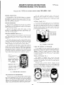
FUEL PUMPSERVICE INSTRUCTIONS
WISCONSINFUEL PUMPS, No. LP-38E, LP-38H and LP-38F (Cold Weather: -65°F)
For all 4 cylinder engine models
The fuel pump, like all other parts of the engine, is subject to wear and you will find that any time after 500 hours
of use, its efficiency
will gradually decrease. This is indicated by the engines faltering
at high speeds or when
heavy loads are suddenly applied.
The pump can easily be
restored to its normal efficiency
by the installation
of a
repair kit. Wisconsin LQ-46 (for LP-38E), LQ-47 (for
LP-38H) or LQ-46A (LP-38F, cold weather, -- 650).
1. Disconnect fuel lines from pump and remove fuel strainer if mounted to pump. Remove fuel pump from adapter
housing by taking out the two mounting screws.
2. File a groove across a point at the union of castings
(15 and 16). This is a positive
location of the fuel
INLET and OUTLET positions
when reassembling.
Remove six head to flange screws (3) and remove fuel
head. Take off screw (2), remove cover (7) and discard
cover gasket (4).
3. Turn fuel head (16) over and remove both valve assemblies (5), and gaskets (6). Note position of valves.
4. Clean head thoroughly with kerosene or diesel fuel and
a fine brush.
5. Place fuel head (16) with diaphragm surface up. Assemble new valve gaskets (6) and mount valve assemblies (5) in positions
shown on illustration.
Press
valves in evenly without distortion,
and stake in place.
6. Mount new cover gasket (4), cover (7) and washer
Securely tighten in place with cover screw (2).
7. Set fuel head assembly aside and proceed to rebuild
lower diaphragm section.
8. Insert the end of a small screw driver into the coils o£
rocker arm spring (12) and remove.
9. Hold mounting bracket (15) in the left hand, with the
rocker arm toward your body and the thumb nail on the
end of link (10). With the heel of right hand on diaphragm (1), compress the diaphragm spring (11), and
the same time pull toward your body. Unhook link (10)
from end of diaphragm and remove.
10. Remove rocker arm pin (13). Note that pin is larger
one end. Drive pin out by means of a punch from
small end.
11. Clean mounting bracket (15) with kerosene or diesel
fuel.
12. Assemble new link (10), bushing (9) and pin (13)
bracket (15) along with rocker arm (14). Stake rocker
arm pin (10) in bracket to keep it in place.
13. Place new diaphragm spring (11) into bracket (15).
peat in reverse order paragraph 9, using a new diaphragm (1). Assemble new rocker arm spring (12).
14. Mount this assembly to adapter on engine using new
flange gasket (17).
15. Crank the engine over to a position where the diaphragm
(1) is laying flat on the mounting bracket (15). Place
the fuel head assembly back in position so the locating
grooves of Step 2 are in Fine, and start the six head
screws approxirfiately
three turns. Again crank the engine over to where the diaphragm (1) is pulled down into mounting bracket (15) to its lowest position. Securely tighten the six head screws (3).
16. Mount fuel strainer to fuel inlet and connect fuel lines.
Ref.
No.
* 1
2
3
* 4
* 5
* 6
7
8
* 9
"10
"11
"12
"13
14
15
16
"17
NOTE: The LQ-46, LQ-47 or LQ-46-A Repoir Kit c~d the pcJ~ts
included
there-ln,
whichareIdendfled
by an asterisk
(*),
aretheonlypartsof thefuelpumpavailable
forservice.
27
Description
DIAPHRAGM
........................................................
COVER
SCREW
..................................................
SCREW,
headto bracketmounting
....................
GASKET,
cover (pulsator in LQ-47)................
VALVE
ASSEMBLY
............................................
GASKET
for valve..............................................
COVER
..................................................................
WASHER
for coverscrew..................................
BUSHING
for rockerarmp~n..............................
LINK
for rocker
arm............................................
SPRING
for diaphragm
........................................
SPRING
for rockerarm......................................
PINfor rocker
arm..............................................
ROCKER
ARM
....................................................
MOUNTING
BRACKET
......................................
FUEL
HEAD
........................................................
GASKET
for mounting
flange............................
No.
Req.
1
I
6
1
2
2
1
1
1
1
1
1
1
1
1
When assured that the problem is with the alternator,
follow the tests outlined in ’Trouble Shooting’.
WIRING CIRCUIT, Flg. 42, Flg. 43
The fool-proof type connectors used to prevent incorrect wiring from the stator to the rectifier and regulator
modules. To disconnect plugs, squeeze outer ends of
receptical and pull apart.
The rectifier
is insulated from ground, but the stator
and regulator
module are grounded to the engine
through their mounting surface. The regulator module
therefore should not be removed and mounted at some
remotelocation. This is a negative groundcircuit. Connect
grotmd strap from negative post of battery to starting motor
flange, or good clean grounding surface on engine.
FLYWHEEL ALTERNATOR
SERVICE PROCEDURE:
PRELINIMARY
TESTS
Wsual Inspection
should be made to eliminate
conditions that may be interpreted
as a defected
alternator.
Examine leads for broken or loose
connections,
and make sure modules are securely
mounted. The regulator
module must be mounted
to a metal surface for grounding purposes, (Test
5.0) while the rectitier module, although insulated
from ground, should be securely mounted for heat
dissipation.
The mounting surfaces must be clean
and free of contaminants, oil, grease, etc.
TROUBLE SHOOTING
FLYWHEELALTERNATOR
12 VOLT - 10 AMP and 25 AMP Systems
Trouble Shooting Procedure is a guide showing
methods of testing
the charging
components.
The
following chart of Tests 1.0 to 4.1 are with the engine
running, and substituting
known good components in
place of suspected faulty components. $totic Tests
5.0 thru 7.2, following the running tests,
are more
conclusive
but some test require special Wisconsin
Test Lights.
Problem:Battery Overcharge
I. 1 If voltage is greater than 13.5 volts
1.2 With engine running
at full RPM,check
battery
voltage
with DCVoltmeter.
I. 3 [[ the charge increases
beyond
13.5 volts.
CheckBattery. Use a Automotive battery in good
condition, fully charged and with clean, tight terminal connections.
CheckAmmeter. Be certain the ammeter is functioning correctly.
Amperage output is regulated
by engine speed. The maximum amperage output
for Model VH4Dis:
Maximum
RPM IOAMP System
2800
1.4 If the charge remains under 13.5
volts.
25 AMP Syetem
9 amps
Possible Cuase& Remedy
Test 1.0 Engine not running
check battery with
DC Voltmeter.
1.1 Place 12 volt light
bulb or carbon pile
across battery to reduce voltabe to below
13.5 volts.
1.3 Faulty regulator, l~eplace, -- static check
regulator
per "rest
No. 5.1.
1.4 Alternator functioning
properly. Check battery condition.
20 amps
SOLENOIDSWITCH_
7
SPARK PLUGS
MOTOR
12 VOLT
3
BATTERY
~"’~L-~--411
~’
I~--REGULATOR
~
I
Fig. 43, WIRINGDIAGRAM
RECTIFIER
WITH
~
I
R at’o
~ Ot ,
n
STARTER
10 AMPor 25 AMP
FLYWHEEL ALTERNATOR
(~ST
~--~
I "~
cHoK
ELECTRICAL SYSTEM
1
term.
ATOR
~.
Makeconnections; for lights at charge
side of ammeter
(negative terminal).
29
/
II
~
~ ~
SWITCH
HI-TEIP
(optional)
COIL
Problem: Low/No Charge
Test
2.0 Proceed with Test
1.0 and 1.1. It is
necessary
to
slightly
discharge
battery
t o make
system work.
2.1 With engine running
at full I~P~.~,, check
bat tery voltage
with DC Voltmeter.
2.2 If the charge rate
increases -2.3 If system does not
charge
2.4 If charge rate increased
with regulator disconnected.
2.5 If the charge rate
does not increase
with regulator disconnected.
Problem: Low/No Charge
Test
3.0
FLYWHEEL ALTERNATOR COMPONENTS
Possible Cause & Remedy
STATIC TESTS
Thefollowingtest equipment
is required:
DF83Analyzer- WisconsinPart, Fig. 44
DFS1Flashlite Tester - WisconsinPart, Fig 44
VOLT-OHM-MILLIAMMETER
Simpson 260 or equal.
functioning
2.2 Alternator
properly. [+attery was
fully charged.
engine with
2.3 Operate
regulator
disconnected (continue withTest
2.4).
2.4 Regulator was at fault.
I~eplace
regulator
module, - static check
regulator
per Test
No. 5.1.
2. 5 Regulator not at fault.
Check Rectifier
per
Test 3.0, 3.1 or static
check per Test 6.0.
Possible
TheDF83Analyzerwasdevelopedfor testing the solid
state ignition andflywheelalternatorcomponents
as furnished on Wisconsinengines. It is very efficiently and
economicallypowered
by four transistor radio type 9 volt
batteries. TheDFS1Flashlite Testeris usedprimarilyfor
checkingcontinuity.
RED
LE~
~+
Cause & Remedy
Test conditions
and procedure the
same as 1.0 and
1.1 it is necessary to slightly
discharge
battery
to make
system work.
[I
BLLEAAC~
-~
INDICATOR
~(
DF83 ANALYZER
3.1 Plug new Rectifier in system.
Run engine at full
RPM.
3.2 If the charge rate
increases
with
new rectifier
in
system.
module was at
3.2 Rectifier
fault.
Permanently install
new rectifier
module.
3.3 If the charge rate
does not increase
with new Rectifier --
not at fault.
3.3 Rectifier
Check Stator per Test
4.0.
DF81 FLASHLITETESTER
Problem: Low/No Charge
Possible
Test 4.0 With engine stopped, unplug all
connectors
between
modules
and stator.
Start
engine and run at
2400 RPM. W|th
AC voltmeter
check voltage between each of the
black stator leads
and ground.
4.1 If one of the two
voltages is zero
or they are over
10% apart. --
Fig. 44
Cause & Remedy
REGULATOR TESTS
Test 5.0 REGULATOR
GROUND
The YJ 60 Regulator modulemust be mountedto a
metal surface for groundingpurposes.Checkfor continuity with a VOM
(R x 1 scale) or test light.
TESTER
RED LEAD
4. 1 The stator is defective
and should be replaced.
Static check stator per
Tests 7.0, 7.1, 7.2.
To Regulator
Body
3O
TESTER
BLACK LEAD
To Ground
RESULT
DF 83-Light On
DF 81 -Light On
VOM-Continuity
Test
7.0
STATOR GROUND
Test
Like the Regulator, the YB 81 and YB 82 Stators must
be grounded. Stator ground can be checked with any
type continuity device.
TEST TESTER
NO. RED LEAD
I
2
Test
TESTER
BLACK LEAD
RESULT
To Ground
DF 83- Light On
DF81-Light On
VOM-Continuity
To Stator
Black Lead
To Other
Black Lead
7.1
To Ground
STATOR CONTINUITY
I
To Ground
2
To Ground
3
STATOR RUNNING VOLTAGE
With the engine stopped, unplug all connectors
between modules and stator.
Start the engine and run at
operating speed. Perform the following tests with an
AC voltmeter:
TEST
NO.
METER
METER
STATOR
RED LEAD BLACK LEAD DEFECTIVE IF:
Either
Reading
To Stator
To Ground
is O
Black Lead
or
To Other
ReadingsVary
To Ground
Stator
more than 10%
Black Lead
BELTDRIVENALTERNATOR
This test should be performed after 7.0 stator ground
test. Use continuity
equipment such as DF81 Flashlite or VOM. ResuJ’ts other than specified indicate a
defective stator.
TEST
TESTER
NO. RED LEAD
7.3
TESTER
BLACK LEAD
RESULT
The t2 vott- 37Amp
Automotivetype Altezrm~is optionally available
in place of the FlywheelAlternator. Nomaintenanceor adjustmentsare
required other thim periodically checkingfor loose, brokenor dirty
wire-terminalconnections,and for proper drive belt tension. Bearings
are pre-lubricated, no additional lubrication is necessary.TheRegulator is an all electronic transistorized devise, therefore no mechanical
contacts or relay adjustmentsare necessaryfor voltage regulation.
Thealternat~ is wiredinto the engineelectrical systemper Fig. 45.
To Stator
Red Lead
VOMo Continuity
To Other
To Ground
IMPORTANT
DF81 - Light On
To Stator
Black Lead
Black Lead
This is a Negative Groundsystem. Charging components will be
damagedif groundedwrongin connectingor jumpingbatteries.
Handlebattery carefully to preventacid
bums.Avoidsparks near battery - gas given
off by battery is explosive
/~
Test 7.2 CONTINUITYwith DF 83 Analyzer
4&-"-°¯.
Stator
Black Lead
Ground
-
On
Ground
-
On
Ground
Stator
Red Lead
-
On
Ground
Stator
Black Lead
Stator
Other
Black Lead
Ground
If light indication
fective.
If stator
test 7.3.
Stator
Black
Other
Lead
On
On
WARNING
PRECAIfrIONS
to be exercised in the use of belt driven alternator:
1. Observeproper polarity wheninstalling battery; negative battery
terminal mustbe grounded.Reverepolarity will deslroy the rectifier
diodesin alternator.
2. As a precautionarymeasure,disconnect groundbattery terminal when
chargingbatl~n’yin vehicle. Connecting
chargerin reversewill destroy
the rectifier diodesin the alternator.
3. DONo~under any circumstances, short the field terminal of the
alternator to ground,as permanent
damage
to the regulatorrmyoccur.
4. DONot, removethe alternator from the vehicle withoutfirst disconnecting the groundedbattery cable.
5. DoNot, operate engine with battery disconnected,or disconnect the
alternator outputlead while the alternator is operating, as aarnping
effect of the batterywill be lost. Thevoltagewill rise to an extremevalue
audpermanentdamageIo the regulator mayoccur.
6. DoNo~disconnect the voltage regulator while the alternator is
operating,becausethe large voltagetransient that occurswhendisconnection takes place maydamagethe regulator.
7. Cautioil: Outputwires from Alternator to Ammeter,and from Ammeter to batteryterminalonstarting solenoidmustbe of sufficientsize for
charging37 amps.UseNc~10 gagestrandedwire, or larger.
YBSI
YB82
30 AMP FLYWHEEL ALTERNATOR
ERMINAL
PLUG
Animproved30 ampflywheel alternator systemis nowavailable as an
optionou Vtt4Dengine~This improved30 ampsystemis capableof higher
outputat lowerenginespeedsover the 25ampflywheelalternator systean.
This new30 ampsystemcan be easily recognizedby the single regulator:
rectifw-r module.Thecombinationregulator-rectifier (YJ70)is mountea
to the cylinder shroudon the VH4D.
TheY J70 mustbe securely mounted
is other than shown, stator is dechecks out good, perform voltage
32
L-57, L.77
Seri s
CARBURETOR
ZENITH MODEL87A8
SERVICE INSTRUCTIONS
DESCRIPTION
The Zenith87-Seriesis a horizontal
carburetor
with a con~ carburetor,because
centricfuel bowl It is a ~balanced
all air for fuel chamberand meteringwell ventilation
and
idling must come through the air cleaner. Air cleaner
restrictions
have a minimuminfluenceon the fuel-airratio
~.
when a carburetoris thus =balanced
The main jet and dischargejet are centrallylocated.The
metering well which completelysurroundsthe discharge
jet is in the centerof the fuel bowl assembly.This constructionpermits extremelyhigh angle operationin any
direction.
The venturi,which is part of the throttlebody casting,
measures the volumeof air that passes through the carburetor.In selectingthe venturisize,the smallestsize
that will permitfull powerdevelopment
shouldbe used.
BOWL VENT
PASSAGE
PITOT TUBE
FUEL
LVE
SEAT
main jet. Fuel from t~e float chamber flows through the
main jet into the metering well. Fuel for idling is drawn
from this well through the calibration,
or metering orifice,
in the center of the idling jet. As the fuel reaches the
idling channel it is mixed with air whicl~ is admitted
through a calibrated
orifice in the channel from the inside
of the air intake to form an emulsion. This emulsion is
discharged into the air stream, to form the idling mixture,
through two holes one of which is controlled
by the idle
adjusting
needle.
Turning the adjusting
needle counterclockwise (out) permits more of the emulsion to reach the
air stream and make the idling mixture richer while turning
the needle in (clockwise) cuts off the amount of the emulsion reaching the air stream and makes the mixture leaner.
HIGH SPEED SYSTEM(Fig. 3)
As the throttle is opened, the suction on the idling system
diminishes,
but the increased volume of air entering the
engine through the venturi
creates
sufficient
vacuttm
(suction) on the discharge jet to draw an emulsion of fuel
and air from the metering well which receives its fuel from
the main jet and its air from the well vent. The flow
characteristics
of the discharge jet are influenced by the
size, location,
and number of holes in the sides of that
part of the jet which is in the metering well, as well as by
FUEL
VALVE
NEEDLE
FUEL
INLET
VENTURI
WELL
LOAT
MAI
Fig,
1 FUEL SUPPLYSYSTEM
METERING
W ELL
OPERATION
FUEL SUPPLY SYSTEM (Fig.
1)
Fuel under normat pressure
entering
the float
chamber
through the fuel valve seat is controlled by the twin float
which, moving on its axle, closes the needle valve when
the fuel reachesthe properlevelin the bowl
IDLE SYSTEM(Fig, 2)
At idling speeds the throttle plate is almost closed, thus a
very high suctionexistsat the edge of the throttleplate
where the idle dischargeholes are located.A11 fuel for
idlingand part throttleoperationis suppliedthroughthe
IDLE AIR
"’
’
:
LE DISCHARGE
"~ ~’~I~I~’~
~////////-~
Fig. 3 HIGH SPEEDSYSTEM
the sizes of the discharge jet orifice,
the size of the maim
jet, and the size of the well vent. The well vent is located
in the air intake and permits air to enter the top of the
metering well around the outside of the discharge jet. The
flow of fuel through the main jet is controlled by the size
of main jet opening.
CHOKESYSTEM(Fig.
4)
Startinga cold enginerequires a much richermixtureof
fuel and air. Moving the choke lever to close the choke
platerestricts
the air entering
the carburetor
(exceptat the
pitot tube, Fig. 1, to the bow1 vent) and increasesthe
suction on the idling system which makes the mixture
richer.
IDLE AIR
¯
N~
IDLE
ADJUSTING
STARTING THE ENGINE
Before cranking the engine, the carburetor
throttle
should
be opened a little
to expose both idle discharge holes to
suction. The choke should be fully closed until the engine
starts,
then opened a little
to prevent stalling
from being
over-choked,
then when the engine is fully warmed up the
choke can be returned
to wide open position
and the
throttle closed to the idling position.
ADJUSTMENTS
~ MAIN JET
Fig. 2 IDLE SYSTEM
Adjust the throttle
stop screw to obtain the desired idling
speed by turning screw in (clockwise)
to increase speed
and out (counter-clockwise)
to decrease engine speed.
Adjust the
the engine
clockwise)
to make it
idle adjusting needle to obtain smooth idling of
at idling speed. Turn the needle out (counterto make the mixture richer,
and in (clockwise)
leaner.
CHOKEPLATE
(CLOSEDPOSITION)
INSPECTION OF PARTS
1. Float Assembly -- Replace if loaded with gasoline,
damaged or if float axle bearing is worn excessively.
Inspect float lever for wear at point of contact with fuel
valve needle. Replace if wear is excessive.
VENTURI
2. Float Axle -- Replace if any wear has occurred on the
bearing surface.
3. Fuel Valve (Needle & Seat) Assembly -- Replace as
complete unit. Wear of any of these parts can seriously
affect the operation of the float.
4. Idle Adjusting
Needle- Inspect
tapered
end of the
needle to make sure it is smooth and free of grooves.
Replace if pitted or grooved.
5. Gaskets,
Seal and Retainer
-- Replace all gaskets,
throttle shaft seal and retainer each time the carburetor
is overhauled.
THROTTLE
PLATE
PARTIALLY
CLOSED
POSITION)
6. Check Specifications.
Verify the correctness
of the
following parts. Numbers will be found on the parts.
Main Jet, Idling Jet and Fuel Valve.
Fig. 4 CHOKESYSTEM
REASSEMBLY
ASSEMBLY OF THROTTLE BODY
1. Install
the fuel valve seat (31) and fibre washer (30),
using Zenith Tool No. C161-85.
2. Install the main discharge jet (32), using a small screwdriver.
3. Install fuel valve needle in seat (31), followed by float
(36) and float axle (35). NOTE: Insert tapered end
float axle (35) into float bracket on side opposite slot
and push through the other side. Press float axle (35)
into slotted side until the axle is centered in bracket.
4. FLOAT SETTING
a. Fuel Level, Check position
of float assembly (36),
for correct measurement to obtain proper fuel level by
using a depth gage. NOTE: Do not bend, twist,
or
apply pcessure on the float body.
b. With bowl cover assembly (26)in an inverted position,
viewed from free end of float (36), the float body must
be centered and at right angles to the machined surface. The float setting is measured from the machined
surface (no g~sket) of float bowl cover to top side
floatbody at highestpoint.This measurementshould
be 31/32% plus or minus 1/32".
c. Bending Float Lever. To increase
or decrease distance between float body (36)and machined surface
(26) use long nosed pliers
and bend lever close to
float body. NOTE: Replace with new float if position
is off more than 1/16".
throttle
body to fuel bowl assembly gasket (37)
5. Install
on machined surface of throttle body (26).
6. Install
idle adjusting needle (17) and spring (18). Screw
needle IN (clockwise) until it seats lightly against the
idle discharge hole, then back it out 1~/2 turns as a preliminary idle adjustment.
SERVICE AND REPAIR PROCEDURE
IDENTIFY
CARUBRETOR
Checkthenumbe~on themetal
idgmification disc pirm~d to th~ top of
thetRrottlc
bodyor indented
in iL Timplainnurnbc~
is theZenith
assembly number, the numb~with the lc[~cr "L" p~-fixcd to it is WisCon Total Powcr’s part numbcxfor the complemassembly.
EXPLODED VIEW (Page 3)
The exploded view identifies
the serviceable
component
parts of the carburetor and shows their relationship
to the
complete assembly. Use the key numbers on the exploded
view to identify and locate parts when performing both the
disassembly and assembly operations.
DISASSEMBLY
SEPARATE CARBURETOR BODIES
Remove the three
bowl assembly
screws (45,
separate fuel bowl (39) from throttle body (26).
46) and
DISASSEMBLE FUEL BOWL
1. Remove the main jet plug (43) and fibre washer (42),
using a 9/16" open end wrench.
2. Remove the main jet (41) and fibre washer (40), using
Zenith Tool No. C161-83 main jet wrench.
3. Remove the Idle Jet (38), using a small screwdriver.
4. Remove the bowl drain plug (44).
DISASSEMBLE THROTTLE BODY
I. Remove the float axle (35) by pressing against the end
with the blade of a screwdriver.
2. Remove the float (36).
3. Remove the fuel valve needle (31), using the fingers.
4. Remove the fuel bowl to throttle
body gasket (37).
5. Remove the main discharge
jet (32), using a small
screwdriver.
6. Remove the fuel valve seat (31) and fibre washer (30),
using Zenith Tool No. C161-85.
7. Remove the idle adjusting needle (17) and spring (18).
REASSEMBLE FUEL BOWL
I. Install
the main jet (41) and fibre washer (40), using
Zenith Tool No. C161-83 main jet wrench.
2. Install
the main jet hex plug (43) and fibre washer
(42), using a 9/16" open end wrench.
3. Install the idle jet (38), using a small screwdriver.
4. Install the bowl drain plug (44).
REASSEMBLE CARBURETOR BODIES
Install
the three bowl assembly screws (45, 46) through
the fuel bowl and into the throttle
body and draw down
firmly and evenly.
CLEANING
Thoroughly clean all metal parts in Bendix Metalclene or
Speedclene and rinse incleaning solvent. Blow out all passages in throttle
body and fuel bowl with reduced air pressure. Be sure all carbon deposits have been removed from
throttle
bore and idle discharge holes. Reverse the flow of
compressed air through all passages to insure the removal
of all dirt.
NEVER USE A DRILL OR WIRE TO CLEAN
OUT JETS OR IDLE HOLES.
SPECIAL TOOLS
The special tools recommended are:
1. C161-83 Main Jet Wrench.
2. C161-85 Fuel Valve Seat Wrench.
35
L-63Serles
CARBURETOR
WISCONSIN
L-63 SERIES
ZENITH MODEL68-7
needlein this passagecontrolsthe suctionon the idle jet and
therebythe idle mixture.Turningthe needlein closerto its seat
results in a greater suction with a smaller amount of air and
thereforea richermixture.Turningthe needleout away from its
seat increasesthe amountof air and reducesthe suction,and a
leanermixtureis delivered.
The fuel is atomizedand mixed with
the air in the passageleadingto the dischargeholesand enters
the air streamat thispoint.
The Zenith 68-7 Series carburetor is of an up-draft single venturi
design with a 1" S.A.E. barrel size and a 7/8" S.A.E. flange.
The carburetors
are made with selective
fuel inlet,
and with or
without a main jet adjustment. These carburetors
are ~balanced"
and "sealed",
and the semi-concentric
fuel bowl allows operation
to quite extreme angles without flooding or starving.
BOWL VENT
FUELINLET
WELL VENT
VENTURI
FUEL VALVE
SEAT
FUEL VALVE
NEEDLE
FLOAT
MAIN JET
Fig. 1
Fig. 3
Fuel supply system, Fig. 1, is made up of a threaded fuel inlet,
fuel valve seat, fuel valve needle, float and fuel bowl. Fuel travels through the fuel valve seat and passes around the fuel valve
and into the fuel bowl. The level of the fuel in the fuel chamber
~s regulated by the float through its control of the fuel valve.
The fuel valve does not open and close alternately
but assumes
an opening, regulated by the float, sufficient to maintain a proper
level in the fuel chamber equal to the demand of the engine according to its speed and load.
High speed system, Fig.3, controlsthe fuelmixtureat partthrottle speedsand at wide open throttle.This systemconsistsof a
venturi,controlling
the maximumvolumeof air admittedinto the
engine;the main iet, which regulatesthe flow of fuel from the
float chamber to the main dischargejet; the well vent, which
maintainsuniformmixtureratio under changingsuctionand engine speeds; and a main discharge jet, which delivers the fuel
into the air stream.
The inside bowl vent as illustrated
by the passage originating
in
~he air intake and continuing through to the fuel bowl, is a method
of venting the fuel bow1 to maintain proper air fuel mixtures even
though the air cleaner may become restricted.
This balancing is
frequently referred to as an "inside bowl vent".
The main jet controls the fuel delivery during part throttle
range
from about one-quarter
to full throttle
opening. To maintain a
proper mixture, a small amount of air is admitted through the well
vent into the discharge jet through air bleed holes in the discharge jet at a point below the level of fuel in the metering well.
The passage of fuel through the high speed system is not a complicated process.
The fuel flows from the fuel chamber thrbugh
the main jet and into the main discharge jet where it is mixed
with air admitted by the well vent, and the air-fuel
mixture is
then discharged into the air stream of the carburetor.
IDLE DISCHARGE HOLES
IDLE
NEEDLE
E PLATE
(Idle Position)
IDLE AIR
CHOKE
(OpenPosition)
IDLE JET
IDLE
PICK-UP
PASSAGE
Fig. 2
Idle system, Fig. 2, consistsof two idle dischargeholes,idle
¯ ir passage,idle adjustingneedle,idle jet, and fuel pick-up
passage.The fuel for idle is suppliedthroughthe main jet to a
well directlybelow the main dischargejet. The pick-uppassage
is connected
to thiswellby a restricted
drillingat the bottomof
this passage.The fuel travelsthroughthis channelto the idle
jet calibration.
The air for the idlemixtureoriginates
backof (or
from behind)the main venturi.The positionof the idle adjusting
36
Fig. 4
Choke system, Fig. 4, consists of a valve mounted on a shaft
located in the aiz entranceand operatedexternallyby a lever
mountedon the shaft.The chokevalveis used to restrictthe air
enteringthe carburetor.This increasesthe suctionon the jets
when startin{~
the engine. The choke valve is of a =semi=automatic s type, having a poppet valve incorporated in its design, which
is controlled
by a spring. The poppet valve opens automatically
when the engine starts
and admits air to avoid over-choking or
flooding of the engine. The mixture required for starting
is considerably
richer than that needed to develop power at normal
temperatures.
As the engine fires and speed and suction are increased, the mixture ratio must be rapidly reduced. This change
is accomplished through adjustment of the choke valve and the
automatic opening of the poppet valve to admit more air when the
engine fires.
MOVE GASKET AWAY FROM
L_
~
CONTACTSHEAD OF PiN
WITHOUT.PRESSURE.
1-5/32" + 1/32"
GASKET
FLOAT SETTING, Fig. 5
If float position is not to the dimension shown, use a long nose
pliers and bend lever close to float body, to obtain correct float
setting.
FUEL LEVEL
The liquid level in float chamber is 17/32 to 19/32 inch below
top of float bowl. This level was established
with a #35 fuel
valve seat at 1½ p.s.i,
and a sight tube approximately
1/4 to
9/32 inch i.d.
37
DISASSEI~BLY
ADJUSTMENTS,Fig.
1
Turn Idle speed screw (5), Fig. 3,in until throttle
valve
slightly opera With engine warmed up and running, turn adjusting screw in or out as required to obtain desired low idle speed
(1000 to 1200 r.p.m.).
Before disassembling: Clean outside of carburetorfrom all
reignmaterial.
When cleaninga completelyassembledcarburetor
do not blow with compressed air, you may collapse the float.
The Idle adjusting needle (14) should be seated lightly (clockwise), then backed out ] ._+ 1/8 turns as a preliminary setting.
With engine warmed up and running at about 1200 R.P.M., fine
tune idle mixture for smooth steady running.
For a complete disassembly, follow the sequence of part reference numbers in the carburetor
exploded view, Fig. 3. Nozz[e
Ref.9, Fig.1 is not removable.
The Main Metering Jet (4), for high speed operation
(not adjustable),
as standard equipment, and used
jority of engine applications.
However, an Adiustable
retor is available,
and the High Speed Adiustment
means of the Needle Assembly, Item 22A of Fig.
following manner:
IMPORTANT:Before removing Throttle
and Choke levers,
note
their position and location.
Optional mounting is available and
may differ from exploded view i11ustration.
CLEANING
1. As a preliminary setting,
1 to 1¼ turns open.
Wash all parts in a mild solvent or fuel. Blow air through orifices (holes) and channels in throttle
body and fuel bowl. Do
not probe with any sharp tools
which might damage small
metering holes.
turn needle out from its
2. With engine warmed up and running
throttle open suddenly.
at idle
Replace all worn or damaged parts -- use all new gaskets.
Note; Body Gasket (18) is put on before float is assembled,
and round opening in gasket fits into groove of Venturi (11).
speed,
Assemble Throttle
Valve (8) and Choke Valve (25) with
numbers facing to the outside, when valves are in the closed
MP0 R TANT: Be careful in tightening brass screws and fittings,
so as not to strip threads and screw driver slots.
Tighten firmly but not excessively.
Valve Seat (16) -- 40 to SO inch pounds torque
Main Jet (22) - SO to 60 inch pounds torque
2
With fuel bowl removed and float assembly in place, turn throttle
body upside down so that float assembly is on top. Check float
height with a depth gauge. Setting should be 1.0|0 inch -+ .020
above bowl gasket. If necessary, bend float arm (at float),
obtain correct height.
SPRING
+1
~
BUOYANCE
|
, SPRING
~:v{~)..
~J
crack
Optional Throttle
’ever (9) located
Be sure that Notch in Venturi is facing toward float needle
valve -- this is clearance for Main nozzle in throttle body.
~
seat about
before speeding up, open Main Jet
3. If engine hesitates
Needle 1/8 to 1/4 turn. Repeat until engine goes from idle
to high speed without hesitation.
REASSEMBLY
FLOAT SETTING, Fig.
is fixed
in the maJet carbuis made by
3, in the
FLOAT
BODY
Fig. 3 EXPLODED VIEW
Instructions and Service Parts Illustration
Fig. 2 FLOAT SETTING
39
MAGNETOSERVICE INSTRUCTIONS
FAIRBANKS-MORSE
TYPE FM-X4B7A
Y-97-$2 (With GD-93C-4 DRIVE GEAR) FORMODEL
VH4D
Wisconsin No.
GENERAL
DESCRIPTION
Coil and condenser
replacement
while simple
are not
re©ommended unless
adequate
test
equipment
is available.
N0 $*ttempt
should
be made to remove magnetic
rotor
from
housing unless specific
instructions
for releasing
the shaft
are available.
Fairbanks-Morse
Type FM-X4B7A Magneto
is designed
and engineered
to provide
quick easy starting
and maximum
dependability
of operation
with minimum service.
The compact a~nico magnetic
rotor
assures
an intensely
hot spark
under most operating
conditions,
SERVICE
INTERNAL TIMING,
PROCEDURE
Then test
the ignition
spark
while engine
is being
cranked.
If a strong
spark is observed,
the magneto is not
the cause of engine malfunction.
If no spark is seen,
proceed with servicing
magneto.
BREAKER POINTS,
FIG.
FIG.
2
If, for any reason,
the magneto ha-~ be~’n dismantled
to
the extent
that the distributor
gear has been removed the
teeth
must be properly
meshed with those of the magnetic
rotor
gear upon reassembly.
The gear teeth
are marked to
facilitate
internal
timing.
The single
marked tooth of the
rotor gear must mesh between the two teeth ,of the distributor
gear designated
by the letter
C.
The first
step in magneto field
servicing
is to examine
the magneto for corroded
high tension
towers,
broken wires,
or high tension
wires not pushed far enough into the magneto
tower to make good contact.
SERVICING
Y-97Series
Marked Tooth of
Rotor Gear Must
Mesh Between
The ’C’ Mark of
Distributor Gear
1
Remove the end cap cover,
distributor
rotor and the end
cap. Then inspect
the breaker
points
for pitting,
oxidation
and shorting.
If points
are worn or shorted,
they should be
replaced.
To remove the poiut
set, take
minal screw releasing
the breaker
condenser
lead.
Remove the fulcrum
the breaker
arm off the fulcrum
support locking screws and lift
off
out the breaker
arm terarm spring,
coil lead and
pin snap ring and slide
pin. Remove the contact
the contact
support.
Fig. 2,
The installation
of new points
is the reverse
of the removal. After the points
have been installed,
they should be
adjusted
to the correct
clearance
of 0.015 inch at high point
of cam. Be sure the points
are clean
and bright
before
adjusting
them. Insert
a screwdriver
in the slot of the support bracket
and pivot
it between the two small
bosses
on
the bearing
support
until
the desired
clearance
is obtained
Then clean the points
again before sealing
the magneto.
TIMING
THE
INTERNAL TIMING GEARS
MAGNETO
TO THE
ENGINE
If the magneto
has been removed
from the engine
for
servicing,
the operator
must follow the engine manufacturer’s
instructions
for timing the magneto to the engine.
Refer to
’Magneto
Timing’
in engine
instruction
manual.
When
installing
the magneto on the engine,
be sure the magneto
is properly
attached
and that the housing to engine gasket
is in good condition.
COIL
SPECIAL
CONDENSER
ADJUST
.015 INCH
BREAKER
SCREWS
PLATE
Fig. 1,
SERVICE
PLACE DISTRIBUTOR
ROTOR IN FIRING
POSITIOCq
No. I CYLINDER
- THEN -
SLOT
BREAKER POINT
NOT
3
Assemble
gear
as follows:
Remove magneto
end cap
cover and turn distributor
rotor until it is in firing position
for No. 1 cylinder.
Retain rotor in this position
and fit the
drive
gear to the impulse
coupling
lugs so that the prick
punch mark on front of gear is located
as shown.
ARM
CONTACT
ADJUSTING
FIELD
TO
LOCKING
GEAR, FIG.
The magneto
is equipped
with
a special
drive
gear
mounted directly
on the impulse coupling.
If it is necessary
to replace
the drive gear, special
care must be exercised
in
reassembly.
It is possible
to be off lgO ° in timing if gear is
improperly
mounted.
MEASURE
BREAKER
POINT
GAP WHEN
OPEN.
DRIVE
ADJUSTMENT
~_..~MOUN T GEAR
WITH ’PRICK
PUNCH’ MARKED
GEAR TOOTH
LOCATED THUS
i
RECOMMENDED
The cam wick, if dry or hard,
should be replaced
with a
new factory
impregnated
wick. Other than this
the magneto
does not require
field
lubrication.
No attempt
should be
made to oil or grease
the magneto bearings.
The magneto
lubricant
should be replaced
only during the overhaul
of the
magneto by a Fairbanks-Morse
authorized
service
station
using recommended lubricant
and factory
engineered
parts.
DRIVE
GEAR
Fig~ 3,
41
DRIVE GEAR MARKING AND ASSEMBLY
SERVICE PARTSLIST
PER-LUXYF50S1/YF50AS1 DISTRIBUTOR
DISTRIBUTOR
APPLICATION
YF50SI and YF5OCSI
YF50ASI and YF50DSI
VH4D, SIDEMOUNT
VH4D, TOP MOUNT
ITEM
NO. PART NO.
DESCRIPTION
--
20121003
20121016
i
--
2
........
20121006
20121020
........
QTY.
DISTRIBUTOR CAP & GASKET
(INCLUDES #i & #4)
1
VENTED
1
DISTRIBUTOR
CAP
ROTOR AND SPACER (INCLUDES
#2 & #5)
1
ROTOR
i
1
3
3
20120003
DUST COVER
*4
20120010
DISTRIBUTOR
*5
20120011
ROTOR SPACER
1
4
6
20120004
MAGNET ASSEMBLY
1
5
7
20120005
ELECTRONIC
SCREWS)
1
8
20120015
ADVANCE
WEIGHTS
9
20120012
ADVANCE
SPRING
--
20121001
GEAR KIT (INCLUDES #10, #II,
#12, #13)
CAP GASKET
MODULE (INCLUDES
SET
SET
1
1
1
i0
........
THRUST
ii
........
SPACER (YFSOASI ONLY)
1
12
........
GEAR
1
13
........
ROLL PIN
1
--
YL394-18
* ALSO SOLD SEPARATELY
WASHER
SET (SELECT ONE)
WIRE, EXTENSION (NOT SHOWN)
13
SHAFTENDPLAY: .001 ¯ - .015"