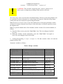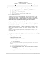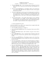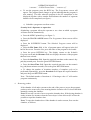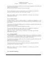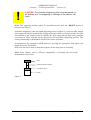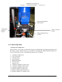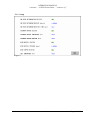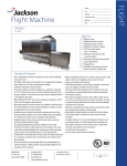
1
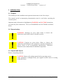
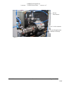
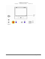
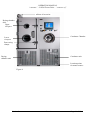
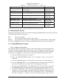
LSG60 Freeze Drier
Title
Customer
SS Reference
Fxxx
Customer Reference
N/A
INSTALLATION AND OPERATION MANUAL
1HZ246
Issue
1
Date
26/10/05
Severn Science Ltd
8 Brunel Way
Thornbury
Bristol
BS35 3UR
Tel 01454 414723
Fax 01454 281680
Please Read This Document before Operating the Machinery
OPERATION MANUAL
“customer” – LSG60 Freeze Drier – “contract ref”
CONTENTS
1.
DOCUMENTATION RECORDS
4
2.
INTRODUCTION
5
2.1
Purpose
5
2.2
General safety
5
2.3
Unpack and inspect
5
2.4
Installation and Commission
2.4.1
Initial setup
2.4.2
Electrical requirements
2.4.3
Mechanical requirements
2.4.4
Lifting and Handling Instructions
2.4.4.1
General
2.4.4.2
Separation of the LSG60
2.4.4.3
Moving of the separate LSG60 units
2.4.4.4
Re assembling the units
2.4.5
Additional Documents to be supplied
3.
OVERVIEW
3.1
4.
6
6
7
7
8
8
8
9
9
11
12
General Description
12
3.2
Main Interfaces
3.2.1
I/O Interface
3.2.2
Operator Interface
14
14
14
FUNCTIONS
17
4.1
Power up
17
4.2
System Access Control
17
4.3
Operation
4.3.1
Initial start up
4.3.2
Running automatic cycles
18
18
18
4.4
Creating/Editing the Recipe
23
4.5
Monitoring the Recipe
24
4.6
Creating/Editing the Program
4.6.1
Creating a new program
4.6.2
Inserting a segment
4.6.3
Deleting a segment
4.6.4
Save/Save as
24
24
26
26
26
4.7
27
Contents
Monitoring the Program
Issue: 1
Page 2 of 42
OPERATION MANUAL
“customer” – LSG60 Freeze Drier – “contract ref”
4.8
5.
6.
Trends
27
4.9
Setup
4.9.1
End Point Determination
4.9.2
Secondary Drying
4.9.3
Automatic Backfill
4.9.4
Automatic Stoppering
27
27
28
28
28
4.10
30
Manual Operation
4.11
Interlocks
4.11.1
Hardwired Interlocks
4.11.2
Software Interlocks
31
31
31
4.12
Alarms
4.12.1
Alarm Types
4.12.2
Alarm Display and Acknowledgement
31
31
31
4.13
Historical Logging
32
OPERATOR DISPLAYS
33
5.1
System Mimics
5.1.1
Home
5.1.2
Setup
5.1.3
Trend
33
33
34
35
5.2
36
Display Navigation
MAINTENANCE
37
6.1
Planned Maintenance
6.1.1
Daily Maintenance
6.1.2
Weekly Maintenance
6.1.3
Six monthly
6.1.4
Calibration
37
37
37
37
37
6.2
Recommended Spares
6.2.1
General
38
38
6.3
Edwards vacuum pump
39
6.4
Manufacturers literature
39
6.5
Self Diagnostic Facilities
39
7.
TECHNICAL SPECIFICATIONS
39
8.
ENVIRONMENT SPECIFICATIONS
40
9.
GLOSSARY
41
Contents
Issue: 1
Page 3 of 42
OPERATION MANUAL
“customer” – LSG60 Freeze Drier – “contract ref”
1. DOCUMENTATION RECORDS
Issue
Documentation Update Details
Date
Approval
1a
Project version 1a developed and issued
for internal review
25/10/05
JH
1
First formal issue to customer.
26/10/05
JH
2
Section 3.2 + section 4.12.2 Alarm socket
location added
15/11/05
JH
Section 2
Issue: 1
Page 4 of 42
OPERATION MANUAL
“customer” – LSG60 Freeze Drier – “contract ref”
2. INTRODUCTION
2.1 Purpose
This manual provides installation and operation instructions for the Freeze dryer.
This manual and all accompanying documentation must be read before operating the
vacuum system.
Important safety information is highlighted as WARNING and CAUTION instructions;
you must obey these instructions. The use of WARNINGS and CAUTIONS are defined
below.
2.2 General safety
!
!
WARNING: Warnings are given where failure to observe the
instruction could result in injury or death to persons.
CAUTION: Cautions are given where failure to observe the
instruction could damage to the equipment, associated equipment or
process. Refer to the accompanying manufacturers’ instruction
manuals for the technical data on individual components.
2.3 Unpack and inspect
Remove all packing material.
!
Section 2
CAUTION: Remove all packing material before operating system.
If the equipment is damaged notify your supplier and the carrier in writing
within three days.
Issue: 1
Page 5 of 42
OPERATION MANUAL
“customer” – LSG60 Freeze Drier – “contract ref”
2.4 Installation and Commission
2.4.1 Initial setup
I. Locate the freeze dryer in the required position, ensuring that the floor is adequate to
support the equipment and that due consideration is given to:
a) Air flow for ventilation (1metre min)
b) Access to framework panels. (1metre min)
c) Adequate space for maintenance. (1metre min)
!
CAUTION: The ventilation holes in the framework panels must not be
blocked or impeded in any way. If they are, overheating and damage may
result.
II. After placement, remove all panels to carry out initial inspection (see sections 3.3 and
3.4). The panels are fitted with lockable latches. To remove panels, unlock the latch
using the key provided, press the top end of the latch lever closest to key hole and lift
bottom end of lever away from panel.
III. Check the sight glass located on the vacuum pump body (refer to figure 4 and to the
manufacturer’s literature). The oil level must be between the MAX and MIN level
indicators.
IV. The vacuum pump exhaust is internally ducted to a stub pipe located on the rear panel
of the condenser unit. Exhaust gases must be ducted away for suitable disposal.
!
!
Section 2
CAUTION: Exhaust gases must be ducted away from the surrounding
atmosphere and suitably disposed.
CAUTION: Do not obstruct any vacuum pump exhaust port (refer to
manufacturer’s manual before operation).
Issue: 1
Page 6 of 42
OPERATION MANUAL
“customer” – LSG60 Freeze Drier – “contract ref”
!
CAUTION: Check that the Gas Ballast control has not been left in the fully
closed position (refer to manufacturer’s manual before operation).
V. The cooling circuit in the drying unit uses a heat transfer fluid (silicone oil). Check the
chamber insulation for signs of oil leaks and confirm that the oil reservoir is
approximately half full (see figure 4).
Severn Science Limited engineers to install and commission
2.4.2 Electrical requirements
!
CAUTION: The unit is factory configured for 415volts (32 amps per phase),
three phase supply. Check that your voltage supply is compatible. If you
operate the unit on the wrong voltage, you will damage it.
Voltage 415Vac
Frequency 50hz
Loading/power consumption 15 KW
Earthing Class 1 (supply earth required)
Fusing 32A
The freeze dryer is supplied with a 32A socket (3p+N+E). Connect this to a suitable socket.
Ensure that all framework panels are refitted before connecting to any services.
!
WARNING: Failure to refit all panels prior to connecting to mains power
may result in injury or death to the operator.
2.4.3 Mechanical requirements
Compressed air – 6 Bar min, ¼ BSP female
Cooling water - 10oC max, 1/2 BSP female, Flow and Return
Hot water defrost - 40oC min, 1/2 BSP female, Flow and Return
Nitrogen backfill – 1Bar, ⅜ BSP female
Pump exhaust – 25mm plain stub pipe
Section 2
Issue: 1
Page 7 of 42
OPERATION MANUAL
“customer” – LSG60 Freeze Drier – “contract ref”
2.4.4 Lifting and Handling Instructions
2.4.4.1 General
The LSG60 Freeze dryer is designed to be moved as two separate units. The drying
chamber assembly (left hand unit) and condenser assembly (right hand unit).
The freeze dryer assembly should therefore be split into these 2 component parts prior
to moving. The silicon oil reservoir fitted at the top and left hand side of the drying
chamber assembly, must be removed if moving this unit through areas with a height
restriction of less than 2110mm.
2.4.4.2 Separation of the LSG60
The LSG60 should be at ambient temperature with the condenser chamber fully drained.
The vacuum valve must be fully closed and the shelves in the fully lowered position
before commencing separation of the two units.
Ensure that power and all other services are safely and fully disconnected from the
LSG60 assembly.
The four jacking feet on each unit should all be in full contact with the ground.
2.4.4.2.1 Draining the Silicon oil fluid circuit
The most efficient means of draining the Silicon oil fluid circuit is by the use of a
vacuum pump and catchpot assembly.
The Silicon oil drain valve is located at the rear and bottom of the drying chamber
unit. The valve can be identified by its yellow handle.
Connect the vacuum pump and catchpot assembly at this point. By opening the valve
the Silicon oil can now be evacuated from the system.
Remove aluminium covers from top of each unit. If required, the Silicon oil reservoir
may now be carefully disconnected and removed.
All services that are connected between the condenser unit and the drying chamber
unit can now be disconnected:1. Unplug all of the (brown) Thermocouple cables from the top rear of the drying
chamber unit (see figure 1).
2. Disconnect the three pneumatic lines form the pneumatic control valves. And
disconnect / unplug the control valve electrical leads.
3. Disconnect the Nitrogen supplies to the control valves.
4. Unplug the two electrical connections to the Unic 10 valve actuator.
5. Immediately beneath the Unic 10 actuator head is an insulated Ø22mm copper
pipe. Remove the short piece of large diameter insulation and disconnect the Straight
union found beneath. A second Ø22mm copper pipe under the above item should
also be disconnected.
6. Remove the four clamps securing the ISO160 flexible metal pipeline to the Unic
10 valve body.
7. Disconnect the two Harting plugs. One to the side of the drying chamber and a
larger one to the rear.
8. Disconnect the Earth link.
Section 2
Issue: 1
Page 8 of 42
OPERATION MANUAL
“customer” – LSG60 Freeze Drier – “contract ref”
9. Disconnect the four grey flexible braided water cooling hoses.
10.Now remove the six 8.0 x 100 socket head capscrews securing the two units
together. Two are located in the top horizontal frame member. A further two in the
middle horizontal frame member. The remaining pair are in the front and rear
verticals, towards the base of the frame work.
11. Un bolt Drying chamber door interlock swith
12. Remove silicon fluid PT100 sensor from rear of chamber (located in pipe
junction) and thread back under pipe work.
13. Disconnect nitrogen inlet valve (V13) on chamber side and unplug Drying
chamber vacuum sensor.
The two units can now be moved apart.
Take great care when moving these units to avoid damage.
Cap and protect all open pipe work and connections.
Protect the ISO 160 valve from ingress of dirt and foreign bodies.
!
WARNING: Please note that the drying chamber unit is top heavy.
Exercise extreme caution when moving.
2.4.4.3 Moving of the separate LSG60 units
The primary means of moving should be by the use of a suitably rated fork lift truck.
For moving through doorways with restricted height and width (1945mm x 810mm
minimum) the use of specially designed transport castors are available from Severn
Science Ltd. When using these castors, they must be restrained in the frame work by
use of the ‘quick release pins’ supplied. These castors are designed for use on level
floors and at a maximum raised height of 8.0 - 10.0mm
(Floor to underside of frame base).
There are 4 Jacking feet positioned towards the corners of each unit. These can be
used (if required) for levelling of the units when finally positioned and re-assembled.
2.4.4.4 Re assembling the units
Reassembly of the two units is a reversal of the disconnect procedure. If used,
remove all transport castors.
Ensure that the two units are in their final position and that they are at the same
height.
All fittings must be clean dry and degreased prior to re-assembly. Application of a
smear of suitable pipe sealant (Loctite 577) should be applied to all compression
fitting olives before reconnection. Do not over tighten.
The Silicon oil fluid circuit must be vacuum filled to avoid any possibility of trapped
air in the system.
Section 2
Issue: 1
Page 9 of 42
OPERATION MANUAL
“customer” – LSG60 Freeze Drier – “contract ref”
PT100
Disconnects
Unic 10 valve actuator
22 mm Straight union
(Silicon oil circuit)
Figure 1
Section 2
Issue: 1
Page 10 of 42
XXX
OPERATION MANUAL
“customer” – LSG60 Freeze Drier – “contract ref”
Heat Exchanger water
cooling hoses
Figure 2
Silicon oil drain valve
2.4.5 Additional Documents to be supplied
Electrical circuit diagrams Publication ref 8408
P&ID publication ref 8484
P&ID Key publication ref 1HY085
Alarm schedule Publication ref 1HY086.
Interlock schedule Publication ref 1HY087.
Stoppering Jack choice ref 8516
Declaration of Conformity publication ref 3IW082-F010
Manufacturer’s Manuals – non specific
Section 2
Issue: 1
Page 11 of 42
OPERATION MANUAL
“customer” – LSG60 Freeze Drier – “contract ref”
3. OVERVIEW
3.1 General Description
The LSG60 Freeze Dryer is for the purpose of drying a wide range of approximately 150
aqueous products in a variety of different sizes of vials.
Freeze drying is a method used to dehydrate materials via a process involving the
sublimation of any water content (in the form of ice) under vacuum conditions. The process
can be subdivided into three (3) stages; freezing, primary drying, where the bulk of the water
content is removed by sublimation, and secondary drying where residual bound water is
removed at higher temperatures. LYOSCIENCE freeze dryers are capable of automatically
performing all these functions in a controlled and reproducible manner.
The equipment consists of a large vacuum drying chamber mounted alongside a refrigerated
condenser with integral vacuum pump. The drying chamber contains nine (9) refrigerated
shelves that can be moved up and down via an hydraulically operated ram for stoppering
processes. Both condenser and drying chambers are fitted with their own refrigeration
systems, with the capability of switching the condenser refrigeration duty to the drying
chamber. The temperature of the product shelves can be controlled between +60oC and –
60oC.
The condenser unit consist of a cylindrical chamber (290 X 860 mm) with a 160 mm
(ISO160) inlet port situated near the front of the chamber and a 40 mm (NW40)
outlet port positioned at the rear of the chamber. The chamber condensing coil is
cooled directly by an integral CFC free refrigeration system mounted in the base of
the unit. During freeze drying, water vapour that is extracted from the product, is
condensed onto the coil, resulting in the formation ice. The chamber has a total ice
capacity of ~15Kg between defrost cycles. The minimum temperature of the
chamber wall under vacuum conditions with no load applied is –80oC.
The condenser inlet is connected to the drying chamber via an electrically actuated
high vacuum butterfly valve. The chamber outlet is connected to the inlet of an
E2M28 vacuum pump. A transparent Perspex cover at the front of the condenser
allows the operator to inspect the ice build up and provides convenient access for
cleaning purposes.
The condenser chamber has a hot water defrost utility. An automatic defrost can be
incorporated into the Freeze Drying cycle.
An Edwards two stage oil-sealed rotary E2M28 vacuum pump is used to evacuate
both condenser and drying chambers. The pump outlet is fitted with a mist filter to
prevent oil mist escaping to the atmosphere. The exhaust of the filter is piped to a
stub connection at the rear of the freeze dryer, which in turn should be connected to
the end user’s exhaust extraction system.
Section 3
Issue: 1
Page 12 of 42
OPERATION MANUAL
“customer” – LSG60 Freeze Drier – “contract ref”
Oil collected in the mist filter is continuously returned into the gas ballast port of the
pump. The pump is operated on gas ballast to reduce the risk of water condensation
in the pump oil (refer also to manufacturers instructions).
The condenser temperature and pressure is monitored with a pirani gauge and a
PT100 respectively; data can be continuously displayed on the touch screen if
required.
The drying chamber is situated alongside the condenser unit (refer to figure 4). The chamber
is fitted with nine temperature controlled product shelves, a refrigeration / heater plant with
heat transfer fluid circuit and a shelf stoppering mechanism. A aluminium door at the front
of the chamber provides access for loading and unloading and is fitted with two toughened
glass view ports (refer to figure 2) which allows the operator to inspect the product during
the freeze drying process.
Each shelf contains an internal network of channels through which the heat transfer fluid can
flow freely and continuously. Heat is extracted or introduced into the fluid via the
refrigeration / heater plant and is then distributed to each shelf in parallel through a common
manifold and liquid re circulating pump. Sensors in the fluid circuit provide feedback for
closed loop temperature control. Temperature control is achieved by modulating the
open/closed state of a valve within the refrigeration system between –100% and 0%. Where
–100% is always open, 0% is always closed.
In order to prevent the cooling compressor from free running, when there is no cooling
demand for sustained periods of time (cooling valve closed), which could result in oil
starvation, a timer control is used. When the Cooling valve has not been called to open by
the PID control for 2 minutes, the Auxiliary compressor is turned off. When the Cooling
valve is next called to open the compressor restarts.
A PT100 sensor mounted in the fluid circuit provides temperature feedback for the loop.
.
The shelves are mechanically linked to a hydraulically actuated ram with variable pressure
settings. The ram moves the shelves up and down allowing automatic stoppering of vials
under vacuum and other controlled atmospheres. Operation of the ram is interlocked with a
safety switch on the front door ensuring that the actuating mechanism is disabled when the
door is opened.
Note: the switch should never be removed or tampered with.
Up to nine (9) product probe sensors (Type T) can be connected and attached to the shelves
or the product to enable continuous monitoring of the process.
The operation of the freeze dryer is controlled from the Eurotherm Visual Supervisor (T800)
and the Eurotherm 2500 modular process controller.
The Visual Supervisor combines process control, data acquisition, data logging, and setpoint
programming and operator functionality. Features include comprehensive event and alarm
management and local data logging facilities. The front-end colour touch screen provides the
Section 3
Issue: 1
Page 13 of 42
OPERATION MANUAL
“customer” – LSG60 Freeze Drier – “contract ref”
user interface. Navigation between the User screens is achieved using standard display
panes and function keys. User screen descriptions can be found later in this document.
The 2500 modular process controller provides the Input/output interface for the control
system, signal conditioning and PID control for the temperature.
These two instruments talk to each other via a serial (RS422) communication link.
The above setup provides a standard control solution for systems such as Freeze dryers.
3.2 Main Interfaces
3.2.1 I/O Interface
The Eurotherm 2500 Process Controller provides the interface for all sensors and plant
actuators.
A relay output is provided responding to any alarm activation, and is intended for connection
to a Building Management System (BMS).
The connection socket for the alarm relay is located on the service panel on the rear of the
freeze dryer.
Refer to page 3 of the Electrical circuit diagrams, Publication ref 8408, for connection details
3.2.2 Operator Interface
The Operator Interface (Visual Supervisor) provides a number of standard (Eurotherm
configured) screens and a number of User (Severn Science configured) screens. The user uses
a combination of these screens to control and monitor the Freeze Drying Process. This also
includes editing and loading Freeze Drying Recipes, monitoring/acknowledging Alarms and
security access.
Section 3
Issue: 1
Page 14 of 42
OPERATION MANUAL
“customer” – LSG60 Freeze Drier – “contract ref”
MENU
KEY
Figure 3
Section 3
Issue: 1
Page 15 of 42
OPERATION MANUAL
“customer” – LSG60 Freeze Drier – “contract ref”
Silicon oil reservior
Drying chamber
door
Upper
viewport
Condenser Chamber
Lower
viewport
Door swing
clamps
Drying
chamber unit
Condenser unit
Location points
for transit castors
Figure 4
Section 3
Issue: 1
Page 16 of 42
OPERATION MANUAL
“customer” – LSG60 Freeze Drier – “contract ref”
4. FUNCTIONS
4.1 Power up
Power up is achieved via the control power switch located below the operator interface (see
Figure 3)
A power indicator illuminates to confirm that control system is on. (see Figure 3)
The Visual Supervisor, after a short self-diagnostic routine, starts up automatically in one of
two different ways:
Hot start, when control power is returned within 1 hour (factory default) the system uses
data about the current program that the Visual Supervisor automatically saves in case of
power failure. Using this information, which is preserved through any power loss, the Visual
Supervisor is able to automatically restart the program from the point it was.
Cold start, the freeze dryer reverts to its default ‘Closed Down’ status as follows:
• Compressors off
• Circulation pump off
• Vacuum pump off
• Valves closed
• Freeze-drying cycle not running
• Shelf temperature setpoint set to -20 oC
Note: The stoppering facility cannot be operated however until the ‘RESET’ button is
pressed. (See figure 3)
System status display reads ‘Closed Down’ (see figure 7)
Power down is achieved via the control power switch located below the operator interface
(see Figure 3)
The power indicator extinguishes to confirm that control system is off.
System status: Visual supervisor, cooling compressors, fluid pump and vacuum pump off,
valves closed. Alarm contact open.
4.2 System Access Control
The Visual Supervisor is set to use individual user accounts. Accounts are configured by the
user and allocated to one of the standard access levels as follows:
1. Locked- Default level on power up. Read only with limited navigational ability.
Section 3
Issue: 1
Page 17 of 42
OPERATION MANUAL
“customer” – LSG60 Freeze Drier – “contract ref”
2. Operator- User is able to download recipes run cycles, view alarm history, historical
program trending, acknowledge alarms and edit user adjustable parameters.
3. Supervisor- As Operator but in addition can and edit recipes and customise the data
logging facility.
4. Administrator- allows individual security accounts to be set up with access rights
appropriate to each level of user.
Access- the user is able to log on by the following operation.
1. Access to Access screen = “MENU” key / “ACCESS” button or “ACCESS” pane.
2. Enter Identity.
3. Enter Password.
When user is logged on it is possible to then change their specific password by the following
operation.
1. Access to Access screen = “MENU” key / “ACCESS” button / “PASSWDS” button
or “ACCESS” pane/ “PASSWDS” button.
2. Enter and confirm new password.
3. Press Change button.
4.3 Operation
4.3.1 Initial start up
Initial start up- before freeze-drying cycles can be run the user first has to switch on the
Cooling compressors, Circulation pump, and Vacuum pump.
1. From the Mimic page, press the ‘START UP’ button.
The freeze dryer controls to the default parameters (see section 6.2.1.2 below)
System status display reads ‘Ready’ (see figure 7)
4.3.2 Running automatic cycles
Run automatic cycles- user is able to load recipes, and run/abort freeze-drying cycles.
The LYOSCIENCE freeze dryer divides the freeze drying cycle into two separate sequences,
the drying profile (program) and the End of Program Sequence (EPS)
Cycle = Program + EPS
Programs can be started as part of a Recipe or independently:
1.
Loading product
!
Section 3
WARNING: The chamber should not be loaded / unloaded when the
shelf temperature is less than 0oC. If it is essential to access the
chamber under these conditions then protective gloves or suitable
PPE should be worn.
Issue: 1
Page 18 of 42
OPERATION MANUAL
“customer” – LSG60 Freeze Drier – “contract ref”
!
CAUTION: The provided ‘stoppering jacks’ must be placed on all
shelves prior to stoppering or damage to the shelves will result
The freeze dryer can be used for both vial and bulk dying. The door to the dying chamber can
be opened by first unscrewing the two swing clamps (see figure 4). With the swing clamps
rotated clear the door can then be opened using the handle.
Note: Do not use excessive force to open the chamber door. If the drying chamber is under
vacuum (for instance when the freeze dryer is first delivered) it will not be possible to open
the chamber door.
Note: To open the chamber door if the chamber is under vacuum, first vent the chamber, as
follows:
a) From the Home screen, press the ‘Vent Valve’ icon. The icon changes from Red
to Green.
b) When the chamber reaches atmosphere, press the ‘Vent Valve’ icon again to
close. The icon changes from Green to Red.
2. Loading/Downloading a recipe- a recipe is a file that contains values for both the
program and the EPS
Parameter variables as follows:
Table 1: Recipe variables
Variable
PROG NAME
NEXT READY
EPD select
EPD rate mbar/s
Description
program to run
start program automatically
End Point Determination selected
End Point Determination fail rate
EPD retest [hrs]
SEC DRY select
SEC DRY temp [oC]
End Point Determination duration
between tests
Secondary Drying selected
Secondary Drying temperature
SEC DRY time [hrs]
Secondary Drying duration
BACKFILL select
BACKFILL press
Automatic Backfill selected
Automatic Backfill pressure setpoint
STOPPER select
FINISH temp [oC]
Automatic Stoppering selected
Cycle completion temperature
Section 3
Issue: 1
Limits
N/A
N/A
YES or NO
Max 10 mbar/s
Min 0.01 mbar/s
Max 60 hrs
Min 0.1 hrs
YES or NO
Max 60 oC
Min -40 oC
Max 60 hrs
Min 0.1 hrs
YES or NO
Max 10 mbar
Min 0.01 mbar
YES or NO
Max 60 oC
Page 19 of 42
OPERATION MANUAL
“customer” – LSG60 Freeze Drier – “contract ref”
Min -40 oC
The user is able to load/download a recipe by the following operation
i. Access to the Load/Save page = ‘MENU’ key / ‘RECIPE’ button
ii. Touch ‘File name’
iii. Select required file from the pick list
iv. Press enter
v.
To access the Recipe menu press the ‘LOAD’ button
Press the ‘DOWNLOAD’ button
The freeze drying cycle will start automatically. The recipe panel changes to blue.
The program panel changes to green indicting that the program is now running.
The time when the program is due for completion is also displayed together with
a number that indicates the number of segments that have been completed.
System status display reads ‘Program’ (see figure 7)
The freeze dryer will automatically run each segment of the selected program
until it is complete. On completion, the cycle will automatically run any End of
Program Sequences selected.
During End Point Determination (EPD) the program panel will change to blue
and the shelf temperature setpoint will remain unchanged. Program state
‘Complete’.
During any of the subsequent sequences the program panel will change to grey.
Program state ‘Idle’.
3. Running a cycle independently- a program can be initiated directly from the Program
menu.
There are three ways to run a program.
a) Run a program now
b) Run a program from a point
c) Schedule a program to run from a time
a) Run a program now
To run a program, first load the required program from the list of stored
profiles.
Section 3
•
Press the MENU printed key (see figure 3)
•
Press the PROGRAMMER button. The Programmer Menu screen will
be displayed.
•
Press the PROGRAM button. The Load/Save Program screen will be
displayed.
Issue: 1
Page 20 of 42
OPERATION MANUAL
“customer” – LSG60 Freeze Drier – “contract ref”
•
Press the file name field . A list of program names will appear in the left
half of the screen. From the list, press the name of the program to be
loaded.
•
Press the green RETURN key. The display returns to the Load /Save
screen and the file name field now displays the name of the program
that has been selected.
•
Press the LOAD button. At this stage, the selected program can either be
run or modified from the Programmer screen. The program name, and
the program status will also be displayed in the program panel in the
top left hand corner of the screen. At this stage, the program status is
‘idle’.
•
Press the RUN button. The program panel changes to green indicting
that the program is now running. The time when the program is due
for completion is also displayed together with a number that indicates
the number of segments that have been completed (see figure 1).
b) Run a program from a point
Select this function if you wish to run a program from a segment other than
the start point of the selected program.
Section 3
•
Press the MENU printed key (see figure 3)
•
Press the PROGRAMMER button. The Programmer Menu screen will be
displayed.
•
Press the PROGRAM button. The Load/Save Program screen will be
displayed.
•
Press the file name field . A list of program names will appear in the left
half of the screen. From the list, press the name of the program to be
loaded.
•
Press the green RETURN key. The display returns to the Load /Save
screen and the file name field now displays the name of the program that
has been selected.
•
Press the LOAD button. At this stage, the selected program can either be
run or modified from the Programmer screen. The program name, and the
program status will also be displayed in the program panel in the top left
hand corner of the screen. At this stage, the program status is ‘idle’.
•
Press the RUN FROM button. A screen headed with the name of the
program is loaded. The total running time for the program selected is
displayed. Press the Run From field (default setting is 00:00:00) and
input the time on the numeric keypad (in hours:minutes:seconds) after the
start of the program when the program should run from. Press the green
RETURN key when inputting is complete. Details of the segment which
will be running when the program starts will then be shown in the lower
half of the display.
Issue: 1
Page 21 of 42
OPERATION MANUAL
“customer” – LSG60 Freeze Drier – “contract ref”
•
To run the program, press the RUN key. The Programmer screen will
appear. The program panel changes to green indicting that the program is
now running. The time when the program is due for completion is also
displayed together with a number that indicates the number of segments
that have been completed (see figure ).
c) Schedule a program to run from a time
Security level : Operator or supervisor
Scheduling a program allows the operator to set a time at which a program
will start and run automatically.
• Press the MENU printed key (see figure 3)
• Press the PROGRAMMER button. The Programmer Menu screen will be
displayed.
• Press the SCHEDULE button. The Schedule Program screen will be
displayed.
• Press the File Name field. A list of program names will appear in the left
half of the screen. From the List, press the name of the program to be loaded.
• Press the green RETURN key. The display returns to the Schedule
Program screen and the file name field now displays the name of the program
that has been selected.
• Press the Start Date field. Input the required start date on the numeric key
pad (day:month:year). Press the green RETURN button.
• Press the Start Time field. Input the required start time on the numeric
key pad (hours:minutes:seconds). Press the green RETURN button.
• To change the number of iterations (number of complete cycle to be
performed sequentially), press the Iterations field. Input the required number
and press the green RETURN button.
Note : The default number of iterations is 1. Entering a value “0” will run the
program continuously.
4.
Removing product
If the chamber is left under vacuum at the end of the process (as per the program),
product can be removed by first ensuring that the isolation valve is closed and then
manually venting the chamber.
Note: Do not use excessive force to open the chamber door. If the drying chamber is
under vacuum (for instance when the freeze dryer is first delivered) it will not be
possible to open the chamber door.
Note: To open the chamber door if the chamber is under vacuum, first vent the
chamber, as follows:
Section 3
Issue: 1
Page 22 of 42
OPERATION MANUAL
“customer” – LSG60 Freeze Drier – “contract ref”
c) From the Home screen, press the ‘Vent Valve’ icon. The icon changes from
Red to Green.
d) When the chamber reaches atmosphere, press the ‘Vent Valve’ icon again to
close. The icon changes from Green to Red.
If the chamber is automatically vented to atmospheric pressure at the end of the
process (as per the program), no further action is required before removing the
product.
!
WARNING: The chamber should not be loaded/unloaded when
the shelf temperature is less than 0oC. If it is essential to access the
chamber under these conditions then protective gloves or suitable
PPE should be worn.
5. Aborting a cycle- the user is able to abort a running cycle at any stage by the following
operation
1. From the Mimic page, press the ‘ABORT’ button.
6. Close down-the user is able to switch off the compressors and fluid pump by the
following operation
1. From the Mimic page, press the ‘CLOSE DOWN’ button.
7. Emergency Stop- the user is able to isolate power to the Stoppering ram, by activating the
E-stop located on the front panel. After an emergency stop condition has occurred, the pressed
E-stop button must be released and the ‘RESET’ button pressed.
4.4 Creating/Editing the Recipe
1. Access to the Recipe Editor page = ‘MENU’ key / ‘RECIPE’ button / ‘EDIT’ button
2. Touching a value in a recipe column, allows a new value to be entered
3. Press the ‘SAVE’ button to save any changes or press the ‘SAVE AS’ to make a copy
of the file
Control variables as follows:
Table 2: Recipe Parameters
Variable
PROG NAME
NEXT READY
EPD select
EPD rate mbar/s
Section 3
Description
program to run
start program automatically
End Point Determination selected
End Point Determination fail rate
Issue: 1
Limits
N/A
N/A
YES or NO
Max 10 mbar/s
Page 23 of 42
OPERATION MANUAL
“customer” – LSG60 Freeze Drier – “contract ref”
EPD retest [hrs]
SEC DRY select
SEC DRY temp [oC]
End Point Determination duration
between tests
Secondary Drying selected
Secondary Drying temperature
SEC DRY time [hrs]
Secondary Drying duration
BACKFILL select
BACKFILL press
Automatic Backfill selected
Automatic Backfill pressure setpoint
STOPPER select
FINISH temp [oC]
Automatic Stoppering selected
Cycle completion temperature
Min 0.01 mbar/s
Max 60 hrs
Min 0.1 hrs
YES or NO
Max 60 oC
Min -40 oC
Max 60 hrs
Min 0.1 hrs
YES or NO
Max 10 mbar
Min 0.01 mbar
YES or NO
Max 60 oC
Min -40 oC
Access level of supervisor or greater is required to make recipe edits.
4.5 Monitoring the Recipe
The Recipe Monitor page can be accessed by touching the MONITOR key from the recipe menu.
The following columns are displayed:
RCP
The recipe variable
SP
The value held in the recipe for each variable
SP(live)
The current live value for each variable. Where the SP and SP(live) values differ,
the value is highlighted in red, providing a useful diagnostic should a recipe download fail.
4.6 Creating/Editing the Program
4.6.1 Creating a new program
The method used to create new programs is based on editing an existing program and
saving the modified program under a new name. When creating a new program for the
first time, use the program called “F010” which has been installed into the Controller
memory prior to shipping. To load the ‘F010’ program, follow the instructions below:
a) Press the MENU printed key (see figure 3)
b) Press the PROGRAMMER button. The Programmer Menu screen will be
displayed.
c) Press the PROGRAM button. The Load/Save Program screen will be displayed.
d) Press the file name field . A list of program names will appear in the left half of
the screen. From the List, press the name of the program to be edited.
e) Press the green RETURN key. The display returns to the Load /Save screen and
the file name field now displays the name of the program that has been selected.
f) Press the LOAD button. At this stage, the selected program can either be run or
modified. To edit the program, press the EDIT button. Details of the program will
appears in the form of a table (referred to as the Editor Screen). Each column of
the table represents a segment of the freeze drying process and each row
Section 3
Issue: 1
Page 24 of 42
OPERATION MANUAL
“customer” – LSG60 Freeze Drier – “contract ref”
describes the freeze drying conditions of either temperature or pressure (pressure
is controlled by the high vacuum valve which is either open or closed). Individual
cells (denoted SP cells) define the temperature or pressure set points for any
particular segment. The top row of cells (referred as ‘segment headings’) define
the duration and the function name (e.g., freezing, primary drying etc) of each
segment.
To configure the segment headings follow the instructions below:
a) Press the segment heading that must be modified. A box displaying data about the
segment will appear. To change the segment name press the segment field. Use
the keyboard to input the required name. To change the segment duration press
the Duration field and use the keyboard to input the required time (hours:
minutes : seconds).
b) Press the green RETURN key. The Program Editor page reappears, showing the
new segment name and duration.
Repeat for any segment heading as necessary.
Note : Changing the duration will not be permitted if the “Ramp @ ” function has been
selected previously anywhere in that segment.
To configure the segment SP cells follow the instructions below:
a) Press the SP cell that must be modified. A box displaying data about the cell will
appear. Press the Type field. A list of optional functions will be displayed. The
choice of functions available include Dwell, Step, Ramp and Ramp@. These
function are described in more detail in Table 3).
b) Select the function that is required and press the green RETURN key.
c) Depending on the function selected, time and temperature set point values can
then be modified by pressing the appropriate field and entering the value on the
numeric keypad (refer to Table 3). Press the DONE button to update the program
table (the set point data and code is displayed in each cell) .
Section 3
Issue: 1
Page 25 of 42
OPERATION MANUAL
“customer” – LSG60 Freeze Drier – “contract ref”
Table 3: Function Descriptions and Coding
Function
Name
Dwell
Step
Ramp
Ramp@
Function
Description
Temperature set point is held for
duration of segment
Temperature ramps to temperature set
point as fast as possible
Temperature ramps to temperature set
point at a constant rate over the
duration of the segment
Temperature ramps to temperature set
point at specified ramp rate
SP
code
D
Set point fields
None
S
Temperature
R
Temperature
R@
Rate (/hr)
Temperature
4.6.2 Inserting a segment
To add a new segment to the freeze drying program, follow the procedure below:
a) From the program editor screen, press the heading that will proceed the new
segment you wish to insert. A box displaying data about the segment will appear.
b) Press the INS SEG key. The New Segment screen will appear.
c) Press the Segment field and use the keyboard to type in the segment name.
d) Press the green RETURN button. Press the OK button on the New Segment
screen. A column will then appear in the program table, representing the new
segment.
e) Configure the new segment as per section 4.6.1.
To save the updated program under the same file name after inserting a segment, or to
save the program as a new file name, refer to section 4.6.4.
4.6.3 Deleting a segment
To remove a segment from the freeze drying program, following the procedure below:
a) From the program editor screen, press the segment header to be deleted. Details
of the segment will appear.
b) Press the DEL SEG button. The Confirm Delete screen will appear. Press OK, to
confirm delete command.
To save the updated program under the same file name after deleting a segment, or to
save the program as a new file name, refer to section 4.6.4.
Note: The first segment of a program can not be deleted.
4.6.4 Save/Save as
Section 3
Issue: 1
Page 26 of 42
OPERATION MANUAL
“customer” – LSG60 Freeze Drier – “contract ref”
To save the updated program under the same file name after editing is complete, or to
save the program as a new file name, follow the procedure below. To insert or delete
segments prior to saving, see sections 5.2 and 5.3.
a) From the program editor screen, press the MENU button on the printed keypad.
From the menu options press the PROGRAMMER button. The Programmer
screen will appear.
b) Press the PROGRAMS button. The load /Save Program screen will appear.
c) To save the edited program under the same file name (shown in the File Name
field), press the SAVE button.
d) To save the edited program under a new file name, press the SAVE AS button.
The Save As screen will appear.
e) Press the File Name field and enter the new file on the keypad.
f) Press the green RETURN key and the OK buttons to confirm.
4.7 Monitoring the Program
4.8 Trends
Security level: Operator or Supervisor
To view a summary of the program status in graphical form, follow the procedure below:
a) Press the program panel in the top left hand corner of the screen. The
programmer screen will appear.
b) Press the PRE-PLOT button. A graph will appear on the screen, headed with the
title of the program in use. Process parameters are logged on the ‘Y’ axis as a
function of time (‘X’ axis) with the direction of time, past to future, moving from
left to right. A curve showing the pre - programmed target values, spanning 4
minutes before and after real time, is plotted in pink. A separate curve, plotted in
red, gives the actual recorded value for the 4 minutes leading up to the current
time. Current time is represented by a vertical line in the middle of the graph.
4.9 Setup
Security level: Supervisor
The Setup page can be accessed by touching the SETUP key from the Home page.
The following sub sequences can be setup:
4.9.1 End Point Determination
End Point Determination (EPD) is an automatic pressure rise test that can be run directly
after the main drying phase, used to determine if the product has reached the required level of
dryness. If this level (determined by the rate of pressure rise in the chamber with the vapour
valve closed) has not been reached then drying continues with temperature and pressure
settings as per the last segment of the program.
Section 3
Issue: 1
Page 27 of 42
OPERATION MANUAL
“customer” – LSG60 Freeze Drier – “contract ref”
Select/unselect the automatic backfill option by pressing the appropriate field which will
toggle between YES and NO.
Note: this can also be used to abort this sequence at any stage.
The rate and repeat test time set point values can be modified by pressing the
appropriate field and entering the value on the numeric keypad.
Note: these changes will be effective immediately, overwriting any previously
downloaded recipe values.
4.9.2 Secondary Drying
Secondary Drying is used to continue drying for a period (user adjustable) at a set
temperature (user adjustable) after the main program and End Point Determination (if used)
have finished.
Select/unselect the automatic backfill option by pressing the appropriate field which will
toggle between YES and NO.
Note: this can also be used to abort this sequence at any stage.
The time and temperature set point values can be modified by pressing the
appropriate field and entering the value on the numeric keypad.
Note: these changes will be effective immediately, overwriting any previously
downloaded recipe values.
4.9.3 Automatic Backfill
Automatic Backfill is used to bring the Product chamber up to a desired level of pressure
(user adjustable), by introducing nitrogen, prior to stoppering. Alternatively the pressure
setpoint can be set to atmosphere to fully vent the chamber with nitrogen.
Select/unselect the automatic backfill option by pressing the appropriate field which will
toggle between YES and NO.
Note: this can also be used to abort this sequence at any stage.
The pressure set point value can be modified by pressing the appropriate field and
entering the value on the numeric keypad.
Note: these changes will be effective immediately, overwriting any previously
downloaded recipe values.
4.9.4 Automatic Stoppering
Section 3
Issue: 1
Page 28 of 42
OPERATION MANUAL
“customer” – LSG60 Freeze Drier – “contract ref”
!
CAUTION: The provided ‘stoppering jacks’ must be placed on
all shelves prior to stoppering or damage to the shelves will
result
Note: The stoppering facility cannot be operated however until the ‘RESET’ button is
pressed. (see figure 3)
Automatic stoppering, when used with stoppering jacks (see figure 5), is used to fully stopper
semi stoppered vials by hydraulically closing the product shelves. Pressure switches are used
for feedback to the control system to indicate the fully stoppered and fully home positions
(see figure 6). These switches can be adjusted to increase/reduce stoppering pressure. This
activity should only be undertaken with Severn Science assistance.
Select/unselect the automatic backfill option by pressing the appropriate field which will
toggle between YES and NO.
Note: this can also be used to abort this sequence at any stage prior to it starting.
Note: these changes will be effective immediately, overwriting any previously
downloaded recipe values.
CAP
ADJUSTABLE SCREW
LOCKING NUT
BASE
Figure 5
Section 3
Issue: 1
Page 29 of 42
OPERATION MANUAL
“customer” – LSG60 Freeze Drier – “contract ref”
Stoppering Hydraulic
flow control
‘Stoppering’
pressure
switch
‘Home’ pressure
switch
Home Hydraulic flow
control
Figure 6
4.10 Manual Operation
Security level: Supervisor
Manual mode- user is able to control the system, by individually operating components from
the mimic screen. Manual mode is accessible by pressing the Manual button (Supervisor
level) on the Home screen. Controllable parameters are as follows:
1. Condenser compressors
2. Cool Cond valve
3. Cool Liq valve
4. Vacuum pump
5. Diathermic pump
6. Vacuum valve
7. Vapour valve
8. Condenser chamber air inlet valve
9. Condenser chamber defrost valve
10. Condenser chamber drain valve
11. Product chamber air inlet valve
12. Product chamber N2 backfill valve
13. Product chamber N2 isolation valve
Section 3
Issue: 1
Page 30 of 42
OPERATION MANUAL
“customer” – LSG60 Freeze Drier – “contract ref”
14. Shelf temperature Auto/Man control
15. Shelf temperature control output
4.11 Interlocks
4.11.1 Hardwired Interlocks
For a complete list of interlocks refer to “Interlock schedule” Publication ref 1HY087.
4.11.2 Software Interlocks
For a complete list of interlocks refer to “Interlock schedule” Publication ref 1HY087.
4.12 Alarms
4.12.1 Alarm Types
Alarm severities are listed in “Alarm schedule” Publication ref 1HY086.
All active alarms are displayed locally and the T800 Run relay is de-energised.
4.12.2 Alarm Display and Acknowledgement
The Alarm pane displays information relating to current alarms.
When at least one Alarm is active but unacknowledged the Alarm pane flashes red, when the
alarm is active but acknowledged the Alarm pane is steady red and if alarm has cleared but is
unacknowledged the Alarm pane flashes black.
Only the most recent alarm tag is displayed, on the Alarm pane, if multiple active alarms
exist.
Acknowledgement- user is able to acknowledge alarms individually or all together using the
following operation:
1. Access to Alarm pane = “MENU” key / “PROGRAMMER” button / “ALARM”
button or “PROGRAMMER” pane / ”ALARM” pane.
2. Press Acknowledge or Acknowledge all button.
History- an alarm history screen displays a list of current and previously active alarms
indicating when they occurred and if appropriate when they were cleared or acknowledged. A
total of 250 alarms can be displayed and when this is exceeded the oldest alarm is deleted
when a new alarm occurs.
User interfacing- any active unacknowledged alarm de-energises the T800 Run relay output.
A relay output is provided responding to any alarm activation, and is intended for connection
to a Building Management System (BMS).
The connection socket for the alarm relay is located on the service panel on the rear of the
freeze dryer.
Refer to page 3 of the Electrical circuit diagrams, Publication ref 8408, for connection details
Section 3
Issue: 1
Page 31 of 42
OPERATION MANUAL
“customer” – LSG60 Freeze Drier – “contract ref”
4.13 Historical Logging
Data can be logged to the 16MB internal memory during the freeze drying cycle. Data is
recorded as a text file (.ASC) and can be later imported into most spreadsheet applications.
The Archive interval is user adjustable (max rate 5secs). Log files can be given an 8character file name (using MS-DOS constraints).
The data logged to disk is:
1. Active alarms
2. Shelf Temp PV
3. Shelf Temp SP
4. Shelf Press PV
5. Shelf Press SP
6. Condenser Temp PV
7. Condenser Press PV
8. Vacuum Valve position
9. Vapour Valve position
10. Liq_Cool status
11. Defrost status
12. Drain status
13. Event history
14. Time/Date
Naming a Log file- the user is able to name a Log file using the following operation.
1. Access to Logging Groups screen = “MENU” key / “LOGGING” button /
“GROUPS” button or “LOGGING” pane / ”GROUPS” button.
2. Enter File Name.
Setting the Archive interval- the user is able to set the Archive interval using the following
operation.
1. Access to Logging Groups screen = “MENU” key / “LOGGING” button /
“GROUPS” button or “LOGGING” pane / ”GROUPS” button.
2. Enter Archive Interval (hh.mm.ss)
The user is able to start logging manually using the following operation:
1. Access to Logging screen = “MENU” key / “LOGGING” button / “MONITOR”
button or “LOGGING” pane / ”MONITOR” pane.
2. Select logging ON.
3. To stop logging select OFF.
The logged data from the internal memory storage can be archived by the user to a removable
device such as a floppy disk or memory stick. The data can be restored for viewing in either a
text editor or a spreadsheet.
The user is able to archive log files using the following operation:
1. Access to Archive Manage page = “MENU” key / “LOGGING” button /
“MANAGE” button or “LOGGING” pane / ”MANAGE” pane.
2. Press ‘EXPORT’ or ‘EXPORT ALL’ button
Section 3
Issue: 1
Page 32 of 42
OPERATION MANUAL
“customer” – LSG60 Freeze Drier – “contract ref”
‘Export’ causes the currently displayed file to be copied to the floppy disk or USB device, as
selected.
‘Export All’ causes all files in the internal archive to be copied to the floppy disk or USB device.
If the device becomes full during archive a message appears asking the user to fit a new disk.
5. OPERATOR DISPLAYS
5.1 System Mimics
5.1.1 Home
Figure 7
Section 3
Issue: 1
Page 33 of 42
OPERATION MANUAL
“customer” – LSG60 Freeze Drier – “contract ref”
5.1.2 Setup
Figure 8
Section 3
Issue: 1
Page 34 of 42
OPERATION MANUAL
“customer” – LSG60 Freeze Drier – “contract ref”
5.1.3 Trend
Example of a single trend page
Figure 9
Section 3
Issue: 1
Page 35 of 42
OPERATION MANUAL
“customer” – LSG60 Freeze Drier – “contract ref”
5.2 Display Navigation
Navigation between displays is as follows:
HOME
SETUP
TREND
Section 10
Issue: 1
Page 36 of 42
OPERATION MANUAL
“customer” – LSG60 Freeze Drier – “contract ref”
6. MAINTENANCE
!
WARNING: There is no safety interlock fitted to the electrical cabinet
door. Ensure that the electrical supply is isolated before starting any
maintenance work.
6.1 Planned Maintenance
When performing the following operations, refer to the components own working instructions
for details on how to carry out the specified items; all of the necessary working instructions are
supplied with this manual.
6.1.1 Daily Maintenance
•
•
Check oil level in vacuum pump
Check chamber door o-ring
6.1.2 Weekly Maintenance
•
•
Check oil level in vacuum pump
Check silicon oil level
6.1.3 Six monthly
•
•
•
•
Check operation of refrigeration cooling fans
Check silicon fluid circuit for leaks
Change the vacuum pump oil
Calibrate gauges
6.1.4 Calibration
It is recommended that all gauging and sensors fitted to this unit be returned to SSL (or a
relevant competent body) for service and calibration at least every 12 months. The time
interval between services must to be reviewed by the customer during the units operating life.
Section 10
Issue: 1
Page 37 of 42
OPERATION MANUAL
“customer” – LSG60 Freeze Drier – “contract ref”
6.2 Recommended Spares
6.2.1 General
Table 4: Recommended Spare Parts List
Description
AXIAL VALVE SERVICE KITS
CHAMBER DOOR SEAL.
Part No
4243 00 10 30 X 1 (3/8”)
4243 00 15 30 X 1 (1/2”)
Ø10.0 silicon ‘O’ ring chord x 4
metres.
Ø305 i/d x 5.0 sect silicon ‘O’ ring.
CONDENSER ACRYLIC
VIEWPORT SEAL.
SILICON OIL CIRCULATION HB527.0003 Huber Unipump ll, 2
PUMP
stage.
SILICON OIL.
LS-1-013 (5ltr)
VACUUM PUMP OIL
H110 25 015. (1ltr)
HYDRAULIC OIL
Mineral oil SAE 30/10 30C/S
(2.5ltr required)
5/2 sol/spring
520 00 380
24vdc
Pressure switch 349 00 18
VAT. Part No. 241079
PNEUMATIC PILOT VALVES.
NW40 VACUUM ISO VALVE
SERVICE KIT.
PNEUMATIC NUPRO VALVE.
HYDRAULIC POWER PACK
AI2-TC
AI2-DC
AI4-TC
AO2
DI8C
DO4
RLY4-FUSE
Section 10
Manufacturer
LEGRIS
SEVERN
SCIENCE
SEVERN
SCIENCE
HUBER
SEVERN
SCIENCE
SEVERN
SCIENCE
SEVERN
SCIENCE
ASCO
VAT
8.0MM and 12.0mm
Bellows kit
SS-4BA-K1
Stem kit
SS-8BK-K5
Body seal kit SS-4BGO-K5-T
Hydraproducts Limited.
Tel. 01452 544052.
2 ch. Isolated universal analog IP
with CJC
2 ch. Isolated universal analog IP
for PT100 and volts
4 ch. Non isolated T/C, with CJC
2 ch. Isolated analogue output mA,
volts
8 ch. Non isolated digital IP
(contacts only)
4 ch. Digital output logic output
10mA max
4 ch. Relay output module with
disconnects
SWAGELOK
WATLOW FIREROD CARTRIDGE
HEATER, 1/2" DIA x 8 1/4" LONG,
Watlow
Issue: 1
Hydraproducts
Limited
Eurotherm
Eurotherm
Eurotherm
Eurotherm
Eurotherm
Eurotherm
Eurotherm
Page 38 of 42
OPERATION MANUAL
“customer” – LSG60 Freeze Drier – “contract ref”
240V 400W, 1/4" COLD AT DISC END,
1/2" COLD AT LEAD END, 39"
TEFLON LEAD AND SEAL.
SVDA-3V25-AO2
SOLID STATE RELAY 25A
Eurotherm
6.3 Edwards vacuum pump
For the Edwards Vacuum pump refer to the individual manufacturers literature for spares.
6.4 Manufacturers literature
Manufacturers literature for all major components have been included.
6.5 Self Diagnostic Facilities
Both T800 and 2500 perform their own self check routines on start-up.
2500 I/O module or hardware errors and Modbus communication failures are checked for within
the configurations and raise alarms if a fault is detected.
7. TECHNICAL SPECIFICATIONS
Section 10
Issue: 1
Page 39 of 42
OPERATION MANUAL
“customer” – LSG60 Freeze Drier – “contract ref”
Table 5: Technical Specifications
FUNCTION
MODEL
o
Minimum condenser temperature (@ 25 C LSG60
ambient)
Minimum shelf temperature (@ 25oC LS40
ambient)
LS60
Shelf cool down times (with both LSG60
(to -35oC)
refrigeration units and with no load,
o
(to –40oC)
from 23 C )
(to –55oC)
(to –60oC)
Maximum shelf temperature
LSG60
Temperature uniformity (between shelves LSG60
(to 0oC)
measured at the inlet)
(to –20oC)
(to –40oC)
(to –60oC)
Temperature uniformity (across each shelf LSG60
(to 0oC)
measured along the front)
(to –20oC)
(to –40oC)
(to –60oC)
Temperature control
LSG60
Condenser capacity
LSG60
o
Defrost time (water inlet temp @ 40 C )
LSG60
LSG60
Vacuum Pump
1. Type
2. Nominal Pumping speed
3. Pump down time (to 0.5 mbar)
LSG60
Electrical
a) Supply
b) Power rating
Dimensions (w x h x d) (not including oil LSG60
reservoir)
Weight
LSG60
Shelf area
LSG60
Noise
LSG60
PERFORMANCE
-80oC
-40oC
-60oC
20 minutes
22 minutes
31 minutes
35 minutes
60oC
+ 0.6oC
+ 0.8oC
+ 1.5oC
+ 2.0oC
+ 0.5oC
+ 0.8oC
+ 1.1oC
+ 1.9oC
+ 0.2oC
15 kg
Approx 10 minutes
Edwards E2M28
28 m3/hr
Approx 10 minutes
415V, 50Hz, 3 ph,
15 KW
1400 x 1940 x 1000
mm
XXX Kg
157 m2
XXX dB
8. ENVIRONMENT SPECIFICATIONS
Section 10
Issue: 1
Page 40 of 42
OPERATION MANUAL
“customer” – LSG60 Freeze Drier – “contract ref”
•
•
•
•
•
Temperature Operation 0 to + 30°C
Temperature Storage -10 to +70°C
Humidity Operation 50 to 85% RH (non condensing)
Humidity Storage 5 to 95% RH (non-condensing)
Protection IP22 (Electrical panel and front panel IP54)
9. GLOSSARY
Section 10
Issue: 1
Page 41 of 42
OPERATION MANUAL
“customer” – LSG60 Freeze Drier – “contract ref”
PID
2500
FLASH memory
RTD
T800
BMS
RS232
PPE
EPS
EPD
Section 10
Proportional / Integral / Derivative
Eurotherm 2500 Input / Output unit
A memory chip that can be rewritten and hold its content without power
Resistance Temperature Detector
Eurotherm T800 Visual Supervisor unit
Building Management system
Serial communications port
Personal Protective Equipment
End of Program Sequence
End Point Determination
Issue: 1
Page 42 of 42