1
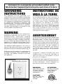
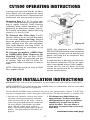
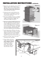
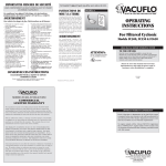
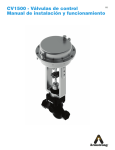
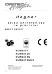
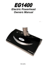
OWNER'S MANUAL
for your new
CV1500
HIGH PERFORMANCE CENTRAL CLEANING SYSTEM
FOR RV APPLICATIONS
READ MANUAL BEFORE OPERATING SYSTEM
TO THE OWNER:
Read the owner's manual thoroughly to ensure the most
efficient use of your DIRT DEVIL® system.
THIS APPLIANCE IS FOR RV USE.
Please be sure this manual/installation
information is left with the power unit or
customer when installation is completed.
PN-9601
IMPORTANT SAFETY INSTRUCTIONS
READ ALL INSTRUCTIONS BEFORE USING THIS VACUUM SYSTEM
When using an electrical appliance, basic precautions should always
be followed, including the following:
WARNING
To reduce the risk of fire, electric shock or injury:
•Do not put any object into open-
ings. Do not use with any open-
ing blocked. Keep openings free of dust, lint, hair, and anything that may reduce air flow.
•Do not pick up anything that is burning or smoking, such as cigarettes, matches, or hot ashes.
•Connect to a properly grounded outlet. See grounding instruc-
tions.
•Turn off all controls before
unplugging.
•Use extra care when cleaning
on stairs.
•Do not use to pick up flammable or combustible liquids such as gasoline or use in areas where they may be present.
•Do not place or store anything on top of power unit - over-heating of motor could occur.
•Any service work required under the motor cover should be performed by an authorized service representative.
•Unplug and disconnect power before servicing.
•Do not use on wet surfaces.
•Do not allow to be used as a toy. Close attention is necessary when used by or near children.
•Use only as described in this manual. Use only manufacturer's recommended attachments.
•Do not use with damaged cord or plug. If appliance is not working as it should, has been dropped, damaged, left outdoors, or dropped into water, return it to a service center.
•Do not pull or carry by cord, use cord as a handle, close a door on cord, or pull cord around sharp edges or corners. Do not run appliance over cord. Keep cord away from heated surfaces.
•Do not unplug by pulling on cord. To unplug, grasp the plug, not the cord.
•Do not handle system or appliance with wet hands.
•Keep hair, loose clothing, fingers, and all parts of body away from openings and moving parts.
SAVE THESE INSTRUCTIONS
FOR RV USE
1
IMPORTANTES MESURES DE SECURITÉ
LISEZ COMPLÈTEMENT LE MODE D'EMPLOI AVANT D'UTILISER
CE SYSTÈME D'ASPIRATEUR.
En employant un appareil électrique, des précautions fondamentales
devraient toujours être prises, y compris:
AVERTISSEMENT
Pour réduire les dangers de feu, d'électrocution, ou de blessure:
•Débrancher et couper le courant •Ne rien mettre dans les fentes et les avant de le réparer.
•Ne pas utiliser sur des surfaces
mouillées.
•Ne pas utiliser comme jouet et surtout faire attention quand on l'emploie prés des enfants.
•Employer seulement tel que décrit dans ce manuel d'emploi et qu'avec les accessories du fabricant.
•Ne pas utiliser si la corde ou la prise électrique est endommagée. Si l'appareil ne fonctionnne pas, est endommagé, est tombé par terre, a été laissé à l'extérieur, ou a été immergé, dans l'eau, veuillez
rapporter l'appareil à un centre de
service.
•Ne pas tirer sur le cordon eléctrique. Ne pas utiliser le cordon eléctrique comme poignée, ni le coincer dans une porte ou l'appuyer sur des coins et boudures tranchants. Ne pas passer l'aspirateur sur le cordon électrique. Eloigner le cordon électrique de la chaleur.
•Ne pas débrancher en tirant sur le cordon électrique. Pour le débrancher, saisir la prise de courant, et non le cordon électrique.
•Ne pas utiliser avec les mains mouillées.
orifices bouchés. Ne pase employer avec des orifices bouches. Éliminer poussiére, cheveux et les autres choses qui peuvent rendre difficile la circulation d'air.
•Gardez cheveux, vêtements amples, doigts, et toutes autres parties du corps loin des orifices et des piéces mobiles.
•Ne pas aspirer queique chose qui brûle ou fume, comme des cigarettes, des allumettes, ou des cendres chaudes.
•Brancher à une prise de courant munie d'une mise à la terre. Voir les reseignements de mise à la terre.
•Éteindre tous les contrôles avant de débrancher.
•Faire bien attention en nettoyant les escaliers.
•Ne pas utiliser pour aspirer des liquides infammables comme l'essence et ne pas employer dans des endroits où ces choses peuvent se trouver.
•Pour reduire les risques de choc electrique, ne pas aspirer de mat
ieres humides.
•Pour eviter d'etre blesse par les pieces en mouvement, debrancher avant l'entretien.
CONSERVEZ CES INSTRUCITONS
POUR VEHICULES DE RECREATION .
2
Connect to a properly grounded outlet only.
Ne brancher l'appareil qu'à une prise avec mise à la terre.
INSTRUCTIONS DE
MISE À LA TERRE
GROUNDING
INSTRUCTIONS
This appliance must be grounded. If it
should malfunction or breakdown, grounding
provides a path of least resistance for electric
current to reduce the risk of electric shock.
This appliance is equipped with a cord having
an equipment grounding conductor and
grounding plug. The plug must be plugged
into an appropriate outlet that is properly
installed and grounded in accordance with
all local codes and ordinances.
Cet appareil doit avoir une mise à la terre.
Si une défectuosité ou autre survenait, la
mise à la terre offre une voie de moindre
résistance au courant électrique, d'où
un risque moins élevé d électrocution.
Cet appareil est équipé d' un cordon
électricque ayant un conducteur et une
fiche de mise à la terre. Cette fiche doit
être branchée dans une prise appropriée
qui a été installée et mise à la terre
convenablement en accord avec le code
électrique de votre région
WARNING
AVERTISSEMENT
Improper connection of the equipmentgrounding conductor can result in a risk
of electric shock. Check with a qualified
electrician or service person if you are in doubt
as to whether the outlet is properly grounded.
Do not modify the plug provided with the
appliance - if it will not fit the outlet, have a
proper outlet installed by a qualified electrician.
Un branchement incorrect de l'équipement
de mise à la terre peut causer un risque
d'électrocution. Si vous avez un doute
concernant la mise à la terre de votre prise,
veuillez faire vérifier votre installation par
un électricien qualifié ou une personne du
service après-vente. Ne pas modifier la
fiche fournie avec l'appareil - si la fiche ne
se branche pas à la prise, faites installer
une prise adéquate par un électricien
qualifié.
The Model CV1500 appliance is for use on a
nominal 120 volt circuit and has a grounding
plug that looks like the plug illustrated in Fig. A.
Make sure that the appliance is connected to
an outlet having the same configuration as
the plug. No adapter should be used with
this appliance.
L'appareil, modéle CV1500 doit être
employé avec un circuit de 120 volts et
avoir une prise qui ressemble à la prise
illustrée sur I'image A.
Grounding Method /
Methode De Mise A La Terrie
Vérifiez que votre appareil est branché sur
une prise ayant la même configuration que
la fiche électrique. Aucun adapteur ne
devrait être utilisé avec cet appareil.
WARNING:
ELECTRIC SHOCK
COULD OCCUR
IF USED ON WET
SURFACES.
CAUTION:
DO NOT USE ON
WET RUG OR
FLOOR.
Figure A / Modele A
3
ATTENTION:
NE PAS UTILISER
SUR TAPIS OU
PLANCHER
MOUILLE.
CV1500 OPERATING INSTRUCTIONS
Inserting hose into valve (Fig.B). Lift lid on
valve. Power unit will automatically come
on. Insert hose into valve. Connect desired
attachment and you are ready to vacuum.
9597 Bag
Changing Bag (Fig. B). To keep your
CV1500 at top efficiency, change the filter
bag at regular intervals. Since cleaning
schedules differ, check frequently in the
beginning to determine proper interval.
To maintain cleanability, replace filter bag
when it is 2/3 to 3/4 full.
To Change the Filter Bag (Fig.B).
Locate canister, lift lid and pull bag collar
off connector. Open new bag, (expand
pleats by gently pulling on the bag). Slide
collar securely onto the inlet connector.
(See Fig.B) Replace with Bag #9597. To
reorder, check bag for instructions or go
to www.rvbags.com
Figure: B
NOTE: This appliance has a THERMAL
PROTECTOR built into the motor to prevent
overheating. If motor will not operate, pull
power cord plug out of receptacle then
reinsert to reset.
To remove secondary #4929 Filter
& #4928/4934 Filter Supports for
Cleaning (Fig.B) Take out bag #9597,
pull support 4934 off connector and out
of canister. Take out 4929 & 4928. For
reassembly, follow instructions in reverse
order.
If motor brushes or bearings are worn out,
the thermal protector will trip off again
after a short period of time. If this happens,
service for this and any other servicing
should be performed by an authorized
service representative.
NOTE: 4929 filter wraps to front of 4928
filter support (Fig.B).
CV1500 INSTALLATION INSTRUCTIONS
WARNING: This unit must be installed in an accessible area with interior vent (Fig D).
AVERTISSEMENT: Cet unité devrait être installé dans un endroit bien aéré et accessible
afin d'éviter la surchauffe de L'appareil.
The Dirt Devil® CV1500 can be installed in any one of four configurations. Figures C, D & E illustrate three configurations, with C being the most common. The one not shown is a variation of D.
2.All dimensions that follow are
approximate. To determine best
configuration for your installation,
temporarily install unit for best
valve location. Be sure there is
clearance to remove top cover and
filter bag.
1.Locate unit centrally so that area to be
cleaned can be conveniently reached
with standard 20' or 30' hose. Also lo cate near grounded electrical receptacle
for easy plug-in connection of motor
cord. Route supply cord so that it
doesn't rest against sharp edges or pinch
points. See grounding instructions on
page 3.
continued onto next page
4
INSTALLATION INSTRUCTIONS continued...
Figure: C
3.Determine valve location and cut 21/4"
(58mm) wide x 33/4" (95mm) high
opening, 97/8" (251mm) above the floor
(Fig C) for upright canister position or
13/4" (45mm) above floor for horizontal
canister position (see fig D).
4.Do not vent into a wall, ceiling or con cealed space of a building or structure.
Unit must be vented with interior vent
or equivalent (see fig D).
5.Place the CV1500 canister in its approxi mate location before installing inlet valve (4940), mounting plate (4865), and
inlet reducer (5531) (see fig. E).
6.Inlet valve switch should be wired at this
point for convenience (See Figure E). In sert pre-stripped ends of 18-2 (1.00 mm 2) low voltage wire into holes on back
of inlet valve (4940), press in firmly and
wires will lock automatically. Pull lightly
to test for locking. Connect other ends
of wire from inlet valve to wire leads
from relay (7090) with wire nuts provided.
Figure: D
7.Install inlet reducer (5531) to inlet con nector (7464), glue if needed. Assemble
inlet valve to wall with mounting plate
(4865) using the four screws provided
(see Figure E). Also, tabs on mount ing plate should face away from inlet valve.
8.Secure unit to floor and or wall with mounting screws provided.
9. Plug in power cord from
motor unit to nearby elec trical receptacle. Route
power supply cord so that
it doesn't rest against
sharp edges or pinch
points. The CV1500
unit operates when the
inlet valve lid is lifted.
Figure: E
Wire
5531 Inlet Reducer
Wire
6452-05
1¹⁄₄” Hose Cut to Length
7477-G
Flex Connector Kit
(3 Fittings)
CV1500
4940, 4935, 4941
Inlet Valve
4865 Mounting Plate
5
VACPAN™
OPERATING INSTRUCTIONS
Simply switch on the VacPan automatic dustpan by pushing the raised tab with your foot.
Switching on the VacPan activates your central vacuum. Brush dirt and debris toward
the VacPan. When cleaning is complete, switch off the VacPan and the central vacuum
system by pushing the raised tab with your foot.
VACPAN™
INSTALLATION INSTRUCTIONS
1. VACPAN requires a minimum 2-1/4" toe kick height.
2. Once the VACPAN location is determined, cut a 6-3/4" long x 1-3/4" high slot in
the cabinet toe kick to accept the VACPAN .
3. Run vacuum tube piping and low voltage wire from the main piping line to the
VACPAN location.
4. Access for final piping connections must be made. From below, cut an access hole
underneath the cabinet, positioned so that final piping connections can be made
through the access hole. Allow for 1/2" vertical play in vacuum tube piping at VacPan location so that final piping connections can be made.
5. Attach low voltage wires to the VACPAN terminal connections marked "low voltage
only".
6. Prior to final installation, check for an airtight seal between the VACPAN and elbow.
Teflon tape may be used if required.
7. Slide VACPAN into mounting slot and secure to toe kick using the two #6 screws
provided.
8. Reach through the access hole and make final piping connections.
6
VACPAN™ II
OPERATING INSTRUCTIONS
VacPanII can be used as both an automatic dustpan and a standard hose inlet.
For automatic dustpan operation, slide top cover up, creating a sweep opening and
automatically switching on central vacuum system. Sweep material into opening. When
complete, slide top cover down, automatically shutting off central vacuum system.
For Standard Hose Inlet operation, ensure top cover is in fully lowered position. Grasp
side finger grips in top cover and flip top cover up. The top cover will lock out of the way.
Lift sprung flapper door open and insert central vacuum hose. Use your central vacuum
hose as you would with any other standard inlet valve.
VACPAN™ II
INSTALLATION INSTRUCTIONS
1. VacPanII Wall Mount can be installed inside any wall with a minimum stud width
of 2-3/4".
2. VacPanII should be located against wall stud.
3. Once the VacPanII location is determined and prior to applying the wallboard,
attach Standard Mounting Bracket to the wall stud so that the center of the
mounting plate is 4" above the subfloor.
4. Attach VacPanII base stopper bracket, thereby allowing appropriated space for
final installation.
5. Run vacuum tube piping and low voltage wire from the main line to VacPanII
location and attach to mounting bracket.
6. Snap off two protruding tabs of VacPanII base stopper bracket and discard.
7. Align VacPanII with mounting bracket. Height adjustment may be required
depending on finished floor.
8. For VacPanII height adjustment: The body can be shortened by scoring along
Quick-Trim Grooves on back of body. The two-piece front cover can be adjusted
for height by twisting apart and engaging the mating teeth of the two parts. The
VacPanII entrance ramp can be slid on mating body grooves.
9. Attach low voltage wires to VacPanII terminal connections.
10.Slide VacPanII into mounting bracket and secure to wall using two #10 x 1-1/2"
screws provided. CAUTION: Do not over-tighten mounting screws as VacPanII
operation can be affected.
7
DIRT DEVIL® CV1500
LIMITED WARRANTY
Your DIRT DEVIL® CV1500, which has been manufactured and inspected in accordance
with carefully specified engineering requirements, is warranted to be free from defects
in material and workmanship for five (5) years.
This warranty is, however, subject to the following qualifications, conditions and limitations
which are set forth to provide you and all users of DIRT DEVIL® products with information
concerning the duration extent, availability and applicability of this DIRT DEVIL® Limited
Warranty, the procedure to be taken to obtain its performance and other information
concerning the DIRT DEVIL® warranty policy.
DURATION OF WARRANTY AND TO WHOM EXTENDED
H-P Products warrants to the customer, the DIRT DEVIL® equipment and accessories
manufactured or supplied by H-P Products to be free from defects in material and
workmanship under normal intermittent use and when properly installed and operated,
for a period of five (5) years from the date of purchase by the first consumer purchaser.
EXCEPTIONS AND LIMITATIONS ON WARRANTY
Defects, malfunctions, failure or damage caused by improper, unreasonable or negligent
use or repair while the warranted parts are in the possession of the consumer are excluded
from the warranty. The warranty does not cover unauthorized repair of the motor assembly.
IMPLIED WARRANTY OF MERCHANTABILITY OR FITNESS FOR A PARTICULAR PURPOSE
ARE LIMITED TO A PERIOD OF FIVE (5) YEARS FROM THE DATE OF PURCHASE BY THE
ORIGINAL CONSUMER.
Some states do not allow limitations on how long an implied warranty lasts, so the above
limitation may be void where prohibited.
THIS WARRANTY IS EXPRESSLY IN LIEU OF ANY OTHER EXPRESS WARRANTIES
AND DOES NOT COVER THE INSTALLATION OF EQUIPMENT. IN NO EVENT SHALL H-P
PRODUCTS BE LIABLE FOR ANY OTHER OBLIGATIONS OR LIABILITIES, ESPECIALLY
FOR ANY INCIDENTAL OR CONSEQUENTIAL DAMAGES TO ANYONE.
Some states do not allow the exclusion or limitation of incidental or consequential
damages, so the above limitation or exclusion may be void where prohibited.
WE NEITHER ASSUME NOR AUTHORIZE ANY PERSON TO ASSUME FOR US ANY
LIABILITY IN CONNECTION WITH THE SALE OR SERVICE OF THIS DIRT DEVIL®
EQUIPMENT OTHER THAN HEREIN ABOVE PROVIDED.
PROCEDURE TO BE TAKEN TO OBTAIN PERFORMANCE OF WARRANTY
To secure repair of any warranted parts under this warranty, the following procedure
should be taken.
The warranted parts, together with satisfactory evidence of the purchase date, must be
delivered, with shipping and delivery charges prepaid, to one of the following: (1) the
Distributor/Dealer from whom purchased; or (2) H-P Products, 512 West Gorgas St.,
Louisville, Ohio 44641.
Upon compliance with the above procedure H-P Products will repair or replace, at its
option, any warranted part which is defective. Such part or parts will be furnished without
cost F.O.B. place of shipment. Return shipment will be made freight collect. All costs for
service calls shall be borne by the one requesting service.
DIRT DEVIL® central vacuums are manufactured
under exclusive license from Royal® Appliance Mfg. Co. by
H-P Products
512 W. Gorgas St. • Louisville, OH 44641
330-875-5556
8
CV1500
PARTS LIST
# Part #
1 7759
1a 7764-DD
1b
1c
2 9597
3 4934
4 4929 5 4928 6 8728
7 7464
8 7455
9 7655-01
11 7599-01
12 7110-01
13 7758
14 9590
15 9591
17 6678
18 7064-02
19 7090
28 7775
29 5148-6
30 5149
31 9601
32 7539-02
33 5737-03
34 7108
9
Name
Qty.
Top Cover
1
Product Label
1
Handle
1
Gasket
1
Bags (3 pack)
Support - Side
1
Filter - Secondary 1
Support - Bottom 1
Canister
1
Inlet Connector 1
Gasket
1
Screw
4
Bushing L.Volt Wire1
Power Cord
1
Gasket - Motor
1
Motor
1
Bracket - Motor 2
Bottom Cover
1
Screw
5
Relay Assy
1
Screw
4
Low Volt Wire (6 ft)
Wire Nut
2
Owners Manual 1
Ground Screw
1
Ground Wire
1
Hex Nuts
3
CV1500
ACCESSORY LIST
1142-B Dusting Tool
1141-B Crevice Tool
9091-B Wand
7029-B
Upholstery Tool
9090-B Rug/Floor Tool
6972-BG RugRat Turbine
Power Brush (Optional)
10
9092-35 Hose Assembly