1
Test and Measurement
Operating Manual
Remote Control for R&S FSH
R&S FSH-K1
1157.3458.02
R&S FSH – Firmware Version 13.1
1157.3564.12-10-
1
Dear Customer,
R&S® is a registered trademark of Rohde & Schwarz GmbH & Co. KG.
Trade names are trademarks of the owners.
1157.3564.12-10-
2
R&S FSH-K1
Enabling Remote Control Option R&S FSH-K1
Contents
Enabling Remote Control Option R&S FSH-K1 ....................................................................................1
Connecting PCs ....................................................................................................................................2
Installation of the driver for the USB optical cable (R&S FSH-Z37) ..............................................2
Serial Port Configuration ...............................................................................................................2
Notational Conventions .........................................................................................................................3
Starting Remote Control Operation ...............................................................................................3
Device Messages ..................................................................................................................................4
Acknowledge Response <ack> .....................................................................................................4
Timeout..........................................................................................................................................4
Functional Description of Commands ...........................................................................................5
Parameter Overview..............................................................................................................................7
Get / Set Parameter.......................................................................................................................7
Get Parameter .............................................................................................................................10
CMD Commands .........................................................................................................................12
Command Description.........................................................................................................................13
General Commands ....................................................................................................................13
Frequency and Span Settings .....................................................................................................18
Amplitude Settings.......................................................................................................................21
Bandwidth Settings ......................................................................................................................25
Sweep Settings............................................................................................................................28
Trace Settings..............................................................................................................................30
Marker..........................................................................................................................................36
Measurement...............................................................................................................................45
Tracking Generator......................................................................................................................52
Power Sensor ..............................................................................................................................58
Channel Power ............................................................................................................................60
Occupied Bandwidth....................................................................................................................62
TDMA Power ...............................................................................................................................64
Distance To Fault Measurement .................................................................................................66
Receiver Mode.............................................................................................................................68
Carrier / Noise Measurement ......................................................................................................71
WCDMA BTS CDP Measurement ...............................................................................................76
Programming Examples ......................................................................................................................82
1157.3564.12
I.1
E-10
R&S FSH-K1
Enabling Remote Control Option R&S FSH-K1
Enabling Remote Control Option R&S FSH-K1
The R&S FSH spectrum analyzer can be fitted with the Remote Control Option R&S FSH-K1, which is
enabled by entering a key code. The key code is based on the unique serial number of the instrument.
To retrofit an option, enable it with a key code.
Operation
Press the GENERAL key.
Use the Rotary knob or the Cursor keys to select the OPTIONS... menu item and confirm the entry
with the ENTER key.
Enter the key code (ten-digit number) for the option with the decimal keys and confirm with the ENTER
key.
If the correct key code is entered, the R&S FSH displays "Remote Control enabled".
If an invalid key code is entered, the R&S FSH displays "Option key error".
The correct key code can then be entered.
1157.3564.12
1
E-10
Connecting PCs
R&S FSH-K1
Connecting PCs
The R&S FSH can be remote controlled by a PC or Laptop equipped with an USB interface or a RS232
interface.
RS232 optical interface
The RS232 optical interface is used for connecting a PC or Laptop. The interface connector is located
at the right-hand side of the R&S FSH, it can be accessed by folding out the support.
The USB Optical Interface Cable R&S FSH-Z37 (supplied with the R&S FSH) or the RS232 Optical
Interface Cable R&S FSH-Z34 are used to make the connection. The optical connection prevents
spurious measurements being caused by interference from these devices.
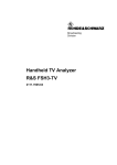
Fold out the support at the rear of the
R&S FSH.
Connect the optical connector of the
RS-232 cable to the optical interface
on the right-hand side of the
R&S FSH.
Connect the USB connector of the
cable to the USB connector of the PC
(R&S FSH-Z37) or the 9-pin D-Sub
connector of the cable to the RS-232
connector of the PC (R&S FSH-Z34).
For the USB cable R&S FSH-Z37:
Install the USB driver supplied on the
R&S FSH CD-ROM.
Installation of the driver for the USB optical cable (R&S FSH-Z37)
The USB driver available on the R&S FSH CD-ROM emulates a serial COM port on the PC. In order to
install the driver on a PC equiped with Windows XP or Windows 2000 please proceed as follows:
Connect the optical USB cable to the PC. The hardware installation wizzard will pop up and state
that it has found a USB to serial bridge.
Insert the R&S FSH CD-ROM.
Select “automatic software installation” and press “Next”. The installation wizzard will automatically
search for the necessary driver and install it.
In case that the wizzard does not find the driver files you will be prompted for manual entry of the
corresponding path. The driver is located on the CD-ROM in folder “\drivers\USB”.
Press “Finish” in order to finalize the installation. The USB cable is now ready for use.
Serial Port Configuration
The serial interface configuration on the PC should be set to
8 data bits, 1 stop bit, no parity
The baud rate can be configured via the Setup menu on the R&S FSH or the SET BAUD command.
The baud rates can be 9.600, 19.200, 38.400, 57.600 or 115.200 Baud. The default baud rate is 19.200
Baud
1157.3564.12
2
E-10
R&S FSH-K1
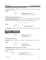
Notational Conventions
Notational Conventions
The following section describes the notational conventions as they are used throughout this document.
Meta Symbol
Specification
:=
Equals
|
Separator for selectable items
“...”
Characters between “ “ are taken as they are, but the “ “ are excluded
(example “,” means an ASCII comma).
[...]
Specifies an optional element
{...}
Specifies an element that may be repeated.
Item
Description
<character>
‘0’ .. ‘9’, ‘a’ .. ‘z’, ‘A’ .. ‘Z’
<string>
<character> { <character> }
<sign>
( ‘+’ | ‘-’ )
<digit>
‘0’ .. ‘9’
<numeric value>
[ <sign> ] <digit> { <digit> } [ . { <digit> } ] [ e | E [ <sign> ] { <digit>} ]
Starting Remote Control Operation
On power-on, the R&S FSH is always in the manual operation state (“LOCAL” state) and can be
operated via the front panel.
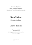
If the R&S FSH receives a remote command the
instrument remains in local state. It is switched to
remote state as soon as it receives the command
“REMOTE” from the PC.
In remote state the front panel access is disabled.
The R&S FSH can be switched back to local state
by sending the LOCAL command.
1157.3564.12
3
E-10
Device Messages
R&S FSH-K1
Device Messages
The remote control command set of the R&S FSH can be grouped into three categories:
• SET commands
SET commands are used
center frequency, span, etc.
to
program
parameters
of
the
instrument
like
• GET commands
GET commands are used to query current settings and data from the instrument like
center frequency, marker, trace data, etc.
• CMD commands
CMD commands are used to initiate an action or a state transition in the instrument like
marker-to-peak, preset, remote state, etc.
Acknowledge Response <ack>
After receiving a SET, GET or CMD command the R&S FSH responds with an “acknowledge”
message. The acknowledge message consists of an ASCII digit (“0” for no error) followed by a Carriage
Return <cr>. The response message indicates if the command or parameter is valid.
A second acknowledge response is generated after the command parameter.
<ack> response:
“0”
No Error.
“1”
Syntax Error. This response is generated when the command sent to the instrument is not
known or when the timeout on data reception expired. It is also generated, when the
parameter or value for the command are in the wrong data format.
“2”
Execution Error. The command sent is not allowed in the current measurement mode.
“3”
Dataset Storage Full. This response is generated when the dataset storage is full.
“4”
Not Allowed. In the current state of the R&S FSH setting this parameter or value is not
allowed.
“5”
Out Of Range. The parameter value is out of range and cannot be programmed.
Timeout
To prevent any lockups in the communication between PC and instrument the data transfer via the
serial interface is monitored by the R&S FSH. There is a timeout time of 60 seconds on every byte
received by the instrument. When the time between 2 bytes in a command or parameter send exceeds
60 seconds the R&S FSH will respond with a ‘Syntax Error’ acknowledge message (“1”<cr>).
Note:
When using remote control commands and the sweep time is less than 30 ms (e.g. Zero
span) the measurement will stop until the complete command is received (in this case all
interrupts are switched off due to the processing of all data points).
1157.3564.12
4
E-10
R&S FSH-K1
Device Messages
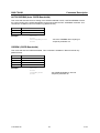
Functional Description of Commands
The command strings and parameter strings are not case sensitive, eg ‘Freq’ is similar to ‘FREQ’.
GET Command
GET commands are used to query parameter settings or measured data from the instrument.
Program syntax:
get<cr>
Response syntax:
<ack><cr>
Program syntax:
<parameter><cr>
<parameter> :=
<string>
This is one of the parameters defined in the following section.
Response syntax:
<ack><cr>
<value><cr>
<value>:=
This field depends on the type of parameter, see the specific value
descriptions
Example:
This command queries the unit from the instrument.
(send ‘get’ command)
(responds ‘command ok’)
(send parameter ‘UNIT’)
(responds ‘parameter ok’)
(responds UNIT value ‘Volt’)
get<cr>
0<cr>
UNIT<cr>
0<cr>
6<cr>
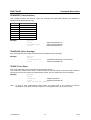
SET Command
SET commands are used to program parameter and setup settings of the instrument.
Program syntax:
set<cr>
Response syntax:
<ack><cr>
Program syntax:
<parameter>,<value><cr>
<parameter> :=
<string>
This is one of the parameters defined in the following section.
<value>:=
This field depends on the type of parameter, see the specific value
descriptions
Response syntax:
<ack><cr>
Example:
This command sets the unit to Watt.
(send ‘set’ command)
(responds ‘command ok’)
(send parameter ‘UNIT’ value is ‘Watt’)
(responds ‘parameter ok’)
set<cr>
0<cr>
UNIT,7<cr>
0<cr>
1157.3564.12
5
E-10
Device Messages
R&S FSH-K1
CMD Command
CMD commands are used to initiate an action or a state transition on the instrument.
Program syntax:
cmd<cr>
Response syntax:
<ack><cr>
Program syntax:
<parameter>,<value><cr>
<parameter> :=
<string>
This is one of the commands defined in the following section
<value>:=
This field depends on the type of parameter, see the specific value
descriptions
Response syntax:
<ack><cr>
Example 1:
This command sets the instrument in Remote Controlled.
(send ‘cmd’ command)
(responds ‘command ok’)
(send parameter ‘REMOTE’)
(responds ‘parameter ok’)
cmd<cr>
0<cr>
REMOTE<cr>
0<cr>
Example 2:
This command saves a dataset on the instrument with the name ‘test’.
(send ‘cmd’ command)
(responds ‘command ok’)
(send parameter ‘SAVE’ with name ‘test’)
(responds ‘parameter ok’)
cmd<cr>
0<cr>
SAVE,test<cr>
0<cr>
1157.3564.12
6
E-10
R&S FSH-K1
Parameter Overview
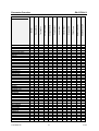
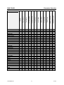
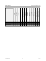
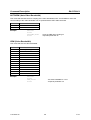
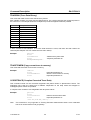
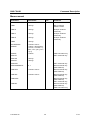
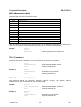
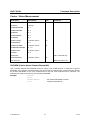
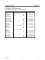
Parameter Overview
In the following tables all parameters and commands are listed with the different measurement modes
they are active in.
Note:
Parameters are not always available; this depends on the type of measurement selected
and other settings.
Get / Set Parameter
1157.3564.12
Receiver Mode
Tracking Gen.
Vector Voltmeter
Isotropic Antenna
Power Sensor
Carrier Noise
Channel Power
Occupied BW
TDMA Power
Distance to Fault
WCDMA BTS CDP
ACCESSORY
ANTDIV
AUTOCISPRBW
AUTODET
AUTORBW
AUTOSPAN
AUTOSWPTIME
AUTOVBW
BAUD
CABLELEN
CABLEMOD
CALKIT
CALKITLEN
CHANNEL
CHMODE
CHPWRBW
CHPWRSTD
CHPWRCSTD
CHPWRUNIT
CHTABLE
CISPRBW
CNCHBW
CNCSTD
CNMANREFPWR
CNMEASMODE
CNMODE
CNNOISECOR
CNNORM
CNPILOTFRQ
CNPWRDISP
CNRATIOCHBW
CNREFMEASMODE
Analyzer
Parameter
*
*
*
*
*
*
*
*
*
*
*
*
*
*
*
*
*
*
*
*
*
*
*
*
*
*
*
*
*
*
*
*
*
*
*
*
*
*
*
*
*
*
*
*
*
*
*
*
*
*
*
*
*
*
*
*
*
*
*
*
*
*
*
*
*
*
*
*
*
*
*
*
*
*
*
*
*
*
*
*
*
*
*
*
*
*
*
*
*
*
*
*
*
*
*
*
*
*
*
*
*
*
7
E-10
Parameter Overview
R&S FSH-K1
CNREFPWR
CNUNIT
CNVISIONFRQ
CTRFREQOFFS
COUPLEDTOREF
DELTA1
DELTA
DELTAALLON
DELTA1ON
DELTAON
DISPLAY
DTFMODE
DYNRANGE
EXTINPUT
FREQ
FREQOFFS
FREQSTART
FREQSTOP
LENUNIT
LIMDEF
LIMLOW
LIMUPP
LIMBEEP
LIMMSG
MARK1
MARK
MARKALLON
MARK1ON
MARKON
MARKMODE
MARKDEMOD
MARKTIME
MARKVOL
MARKIMPREF
MARKMEASY
MATHMODE
MEAS
MEASTIME
NDBDOWNVAL
OBWSTD
OBWCSTD
OBWCHBW
OFFSETLEN
PREAMP
PRESETSET
1157.3564.12
WCDMA BTS CDP
Distance to Fault
TDMA Power
Occupied BW
Channel Power
Carrier Noise
Power Sensor
Isotropic Antenna
Vector Voltmeter
Tracking Gen.
Receiver Mode
Analyzer
Parameter
*
*
*
*
*
*
*
*
*
*
*
*
*
*
*
*
*
*
*
*
*
*
*
*
*
*
*
*
*
*
*
*
*
*
*
*
*
*
*
*
*
*
*
*
*
*
*
*
*
*
*
*
*
*
*
*
*
*
*
*
*
*
*
*
*
*
*
*
*
*
*
*
*
*
*
*
*
*
*
*
*
*
*
*
*
*
*
*
*
*
*
*
*
*
*
*
*
*
*
*
*
*
*
*
*
*
*
*
*
*
*
*
*
*
*
*
*
*
*
*
*
*
*
*
*
*
*
*
*
*
*
*
*
*
*
*
*
*
*
*
*
*
*
*
*
*
*
*
*
*
*
*
*
*
*
*
*
*
*
*
*
*
*
*
*
*
*
*
*
*
*
*
*
*
*
*
*
*
*
*
*
*
*
*
*
*
*
*
*
*
*
*
*
*
*
*
*
*
*
*
*
*
*
*
*
*
*
*
*
*
*
*
*
*
*
*
*
*
*
*
*
*
*
*
*
*
*
*
*
*
*
*
*
*
*
*
*
*
*
8
*
*
*
*
*
*
*
E-10
R&S FSH-K1
Parameter Overview
PSCRCD
PWRSSTD
RANGE
RBW
REFLUNIT
REFLVL
REFLVLOFFS
RFINPUT
SCANMODE
SCANSTART
SCANSTOP
SCANSTEP
SPAN
SSCRCD
SWPCONT
SWPTIME
TDMASTD
TDMACSTD
TGATT
TGLVL
TGMODE
THRLOW
THRUPP
TRACEAVG
TRACEDET
TRACEMODE
TRD1
TRD1X
TRD1Y
TRD1Z
TRD2
TRIGDEL
TRIGLVL
TRIGSRC
UNIT
VBW
VVREF
1157.3564.12
WCDMA BTS CDP
Distance to Fault
TDMA Power
Occupied BW
Channel Power
Carrier Noise
Power Sensor
Isotropic Antenna
Vector Voltmeter
Tracking Gen.
Receiver Mode
Analyzer
Parameter
*
*
*
*
*
*
*
*
*
*
*
*
*
*
*
*
*
*
*
*
*
*
*
*
*
*
*
*
*
*
*
*
*
*
*
*
*
*
*
*
*
*
*
*
*
*
*
*
*
*
*
*
*
*
*
*
*
*
*
*
*
*
*
*
*
*
*
*
*
*
*
*
*
*
*
*
*
*
*
*
*
*
*
*
*
*
*
*
*
*
*
*
*
*
*
*
*
*
*
*
*
*
*
*
*
*
*
*
*
*
*
*
*
*
*
*
*
*
*
*
*
*
*
*
*
*
*
*
*
*
*
*
*
*
*
*
*
*
*
*
*
*
*
*
*
*
*
*
*
*
*
*
*
*
*
*
*
*
*
*
*
*
*
*
*
*
*
*
*
*
*
*
*
*
*
*
*
*
*
*
9
*
*
*
*
*
E-10
Parameter Overview
R&S FSH-K1
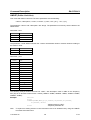
Get Parameter
1157.3564.12
WCDMA BTS CDP
Distance to Fault
TDMA Power
Occupied BW
*
*
Channel Power
*
*
Carrier Noise
*
Power Sensor
Vector Voltmeter
*
Isotropic Antenna
Tracking Gen.
CABLELOSS
CARRFREQERR
CCORRTRACE
CCORRTRACEBIN
CHPWR
CNVALUE
CPICHEIRAT
CPICHPWR
CPICHSLOTNR
CPICHSYMEVM
CTRACE
CTRACEBIN
DELTAALL?
ELCABLENVAL
EXTREF
IDN?
LEVEL
LIMCHKREMOTE
LIMLIST
LIMPASS
MARKALL?
MTRACE
MTRACEBIN
OCCBW
NDBDOWN
PCCPCHEIRAT
PCCPCHPWR
PCCPCHPWRREL
PCCPCHSYMEVM
PSCHPWR
PSCHPWRREL
PWR
REFL
REFLCAL
REFLVECTCAL
SSCHPWR
SSCHPWRREL
STB?
SYNCRESULT
TDMAPWR
TEMP
THRPASS
Receiver Mode
Analyzer
Parameter
*
*
*
*
*
*
*
*
*
*
*
*
*
*
*
*
*
*
*
*
*
*
*
*
*
*
*
*
*
*
*
*
*
*
*
*
*
*
*
*
*
*
*
*
*
*
*
*
*
*
*
*
*
*
*
*
*
*
*
*
*
*
*
*
*
*
*
*
*
*
*
*
*
*
*
*
*
*
*
*
*
*
*
*
*
*
*
*
*
*
*
*
*
*
*
*
*
*
*
*
*
*
*
*
*
*
*
*
*
*
*
*
*
*
*
*
*
*
*
*
*
*
*
*
*
*
*
*
*
*
*
10
*
*
*
*
*
E-10
1157.3564.12
Receiver Mode
Tracking Gen.
TOTPWR
TRACE
TRACEBIN
TRANSCAL
TRANSVECTCAL
VECTVOLT
Analyzer
*
*
*
*
*
*
*
*
*
*
*
*
*
*
*
11
Channel Power
Occupied BW
TDMA Power
Distance to Fault
*
*
*
*
*
*
*
*
*
*
WCDMA BTS CDP
Carrier Noise
Power Sensor
Isotropic Antenna
*
Vector Voltmeter
R&S FSH-K1
Parameter Overview
Parameter
E-10
Parameter Overview
R&S FSH-K1
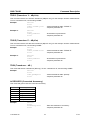
CMD Commands
WCDMA BTS CDP
Distance to Fault
TDMA Power
Occupied BW
Channel Power
Carrier Noise
Power Sensor
Isotropic Antenna
Vector Voltmeter
Tracking Gen.
Receiver Mode
Analyzer
Parameter
AUTOSDSNGL
*
AUTOSDMUL
*
CAL_DTF
CAL_TGSCLRFL
CAL_TGSCLTRN
CAL_TGVECRFL
CAL_TGVECTRN
INIT
LOCAL
LVLADJUST
MARKNXTPK
MARKPK
MARKMIN
MARKTOCENT
LIMDEL
MARKTOLVL
PRESET
PWRTOREF
RECALL
REMOTE
SAVE
THROFF
TRACETOMEM
WAIT
ZERO
VVTOREF
Note:
*
*
*
*
*
*
*
*
*
*
*
*
*
*
*
*
*
*
*
*
*
*
*
*
*
*
*
*
*
*
*
*
*
*
*
*
*
*
*
*
*
*
*
*
*
*
*
*
*
*
*
*
*
*
*
*
*
*
*
*
*
*
*
*
*
*
*
*
*
*
*
*
*
*
*
*
*
*
*
*
*
*
*
*
*
*
*
*
*
*
*
*
*
*
*
*
*
*
*
*
*
*
*
*
*
*
*
*
*
*
*
*
*
*
*
*
*
*
*
*
*
*
*
*
*
*
*
*
*
*
*
*
*
*
*
*
*
*
*
*
*
When the instrument is in the state standby (Off) only the parameters IDN?, BAUD and
MEAS are available.
1157.3564.12
12
E-10
R&S FSH-K1
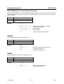
Command Description
Command Description
General Commands
Command
Parameters
Unit
IDN?
BAUD
Comment
GET command only
0...4
SET command only
REMOTE
LOCAL
PRESETSET
0...1
PRESET
INIT
WAIT
STB?
GET command only
EXTINPUT
0, 1
SAVE
<string>
RECALL
<string>
EXTREF
0…3
DISPLAY
0...1
GET command only
TEMP
GET command only
IDN?
This command returns the instrument ID string.
This string contains: <manufacturer>,<model number>,<serial number>,<software version>.
<model number>:
03, 13, 23 for the according R&S FSH3 model
06, 26 for the according R&S FSH6 model
18 for the according R&S FSH18 model
Example:
1157.3564.12
get<cr>
0<cr>
idn?<cr>
0<cr>
Rohde&Schwarz,23,100212,V11.0
13
‘query ID string
‘responds parameter ok
‘instrument ID string
E-10
Command Description
R&S FSH-K1
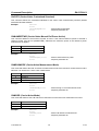
BAUD (Serial baud rate)
This command sets the serial interface baud rate. The default baud rate is 19.200 Baud.
Value
0
1
2
3
4
Example:
Baud rate
19.200
38.400
57.600
115.200
9.600
set<cr>
0<cr>
baud,3<cr>
0<cr>
‘set baud rate on 115.200
‘responds ok with current baud rate
‘instrument is set to new baud rate
REMOTE
This command sets the instrument to remote state. Front panel interaction is disabled.
Example:
cmd<cr>
0<cr>
remote<cr>
0<cr>
‘set instrument to remote
‘responds parameter ok
LOCAL
This command sets the instrument to local state. Front panel operation is enabled.
Example:
1157.3564.12
cmd<cr>
0<cr>
local<cr>
0<cr>
‘set instrument to local
‘responds parameter ok
14
E-10
R&S FSH-K1
Command Description
PRESETSET (Preset Setting)
This command selects the preset settings. When selecting the Custom Preset Setting a Preset Dataset
must be available.
Value
0
1
Example:
Preset Setting
Default
Custom
set<cr>
0<cr>
presetset,1<cr>
0<cr>
‘use custom preset settings’
‘responds parameter ok’
PRESET
This command sets the instrument to the preset settings.
Example:
cmd<cr>
0<cr>
preset<cr>
0<cr>
‘set instrument to preset
‘responds parameter ok
INIT
This command starts / re-starts a new sweep.
Example:
cmd<cr>
0<cr>
init<cr>
0<cr>
‘start new sweep
‘responds parameter ok
WAIT
This command is used to synchronize with the end of a sweep. After sending the WAIT command the
<ack> acknowledge is holdoff until the sweep is complete.
Example:
cmd<cr>
0<cr>
wait<cr>
0<cr>
‘wait for end of sweep
‘responds parameter ok, sweep complete
STB?
This command returns the instrument status. The status indicates any
measurements to be questionable (response: ‘1’) or not (response ‘0’).
Example:
get<cr>
0<cr>
stb?<cr>
0<cr>
0<cr>
1157.3564.12
15
settings/conditions that causes
‘query status
‘responds parameter ok
‘status: o.k.
E-10
Command Description
R&S FSH-K1
EXTINPUT (External Input)
This command switches between external trigger input and external reference input on the external
input connector. Default is ‘External Trigger’.
Value
0
1
Example:
External Input Connector
External Trigger
External Reference
set<cr>
0<cr>
extinput,1<cr>
0<cr>
‘enable external reference on input connector
‘responds parameter ok
SAVE
This command saves the current setting and measurement in the specified dataset. If the dataset exists
it will be overwritten. Dataset names are not case sensitive.
Example:
cmd<cr>
0<cr>
save,mydata.001<cr>
0<cr>
‘save settings to dataset “MYDATA.001”
‘responds parameter ok
RECALL
This command recalls a stored dataset. Dataset names are not case sensitive.
Example:
cmd<cr>
0<cr>
recall,mydata.001<cr>
0<cr>
‘recall settings from dataset “MYDATA”
‘responds parameter ok
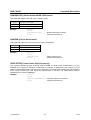
EXTREF (External Reference status)
This command returns the external reference status.
Value
0
1
2
3
Example:
1157.3564.12
Status external reference
Disabled
Out of range
Catching
Locked
get<cr>
0<cr>
extref<cr>
0<cr>
1<cr>
‘get status of external reference
‘responds parameter ok
‘response status out of range
16
E-10
R&S FSH-K1
Command Description
DISPLAY
This command turns the display on or off.
Value
0
1
Example:
Off
On
set<cr>
0<cr>
display,0<cr>
0<cr>
‘turn display off
‘responds parameter ok
TEMP (Temperature)
This command returns the current temperature inside the instrument.
Example:
get<cr>
0<cr>
temp<cr>
‘query temperature
0<cr>
‘responds parameter ok
32.6
‘instrument temperature (Celsius)
1157.3564.12
17
E-10
Command Description
R&S FSH-K1
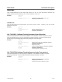
Frequency and Span Settings
Command
Parameters
Unit
FREQ
<numeric value>
Hz
FREQOFFS
<numeric value>
Hz
SPAN
<numeric value>
Hz
AUTOSPAN
0, 1
CHANNEL
<numeric value>
CHTABLE
<string>
CTRFREQOFFS
<numeric value>
Comment
Hz
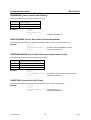
FREQ (Frequency)
This command sets the center frequency.
The start and stop frequency of the instrument is defined by the current center frequency and span.
Example:
set<cr>
0<cr>
freq,950E6<cr>
0<cr>
‘set center frequency to 950 MHz
‘responds parameter ok
FREQOFFS (Frequency Offset)
This command sets the frequency offset.
The new center frequency is the current frequency plus the frequency offset.
Example:
set<cr>
0<cr>
freqoffs,10E6<cr>
0<cr>
‘set frequency offset to 10 MHz
‘responds parameter ok
SPAN
This command sets the span.
The start and stop frequency of the instrument is defined by the current center frequency and span.
The <numeric value> = 0 is used for Zero Span.
Example:
1157.3564.12
set<cr>
0<cr>
span,20E6<cr>
0<cr>
‘set span to 20 MHz
‘responds parameter ok
18
E-10
R&S FSH-K1
Command Description
AUTOSPAN
This command switches span mode AUTO on/off (Measure Mode: Channel Power or Occupied BW)
Value
0
1
Example:
Span Mode
Auto Off
Auto On
set<cr>
0<cr>
autospan,1<cr>
0<cr>
‘set Auto span On
‘responds parameter ok
CHANNEL (Channel Number)
This command defines the channel number. Use CHTABLE command to select a channel table first.
Example:
set<cr>
0<cr>
channel,55<cr>
‘selects channel no. 55
CHTABLE (Channel Table)
This command selects a channel table for the channel mode.
Example:
set<cr>
0<cr>
chtable,FMBand<cr>
0<cr>
‘selects channel table “FMBand”
‘responds parameter ok
CTRFREQOFFS (Coupled To Reference channel - FREQuency OFFSet)
This command couples the frequency of the noise channel in Carrier / Noise measurements to the
frequency of the reference channel. The command sets the frequency offset of the noise channel from
the reference channel.
Example:
1157.3564.12
set<cr>
0<cr>
ctrfreqoffs,16E6<cr> ‘set frequency offset from ref. channel to 16 MHz
0<cr>
‘responds parameter ok
19
E-10
Command Description
R&S FSH-K1
COUPLEDTOREF (Coupled To Reference channel)
This command couples the frequency of the noise channel in Carrier / Noise measurements to the
frequency of the reference channel.
Value
0
1
Example:
1157.3564.12
CoupledToRef
Off
On
set<cr>
0<cr>
coupledtoref,1<cr>
0<cr>
‘set coupled to on
‘responds parameter ok
20
E-10
R&S FSH-K1
Command Description
Amplitude Settings
Command
Parameters
REFLVL
<numeric value>
REFLVLOFFS
<numeric value>
RANGE
0...36
DYNRANGE
0, 1
UNIT
0...8
RFINPUT
0, 1
PREAMP
0, 1
Unit
Comment
Uses current unit
dB
REFLVL (Reference Level)
This command sets the reference level using the current unit.
Example:
set<cr>
0<cr>
reflvl,-30<cr>
0<cr>
‘set reference level to –30dBm
‘responds parameter ok
REFLVLOFFS (Reference Level Offset)
This command sets the reference level offset in dB.
The new reference level is the current reference level plus the reference level offset.
Example:
1157.3564.12
set<cr>
0<cr>
reflvloffs,-6<cr>
0<cr>
‘set reference level offset to –6 dB
‘responds parameter ok
21
E-10
Command Description
R&S FSH-K1
RANGE
This command defines the range.
Value
0
1
2
3
4
5
6
7
8
9
10
11
12
13
14
15
16
17
18
19
20
21
22
23
24
25
26
27
28
29
30
31
32
33
34
35
36
Example:
1157.3564.12
Range
10 dB/DIV
5 dB/DIV
2 dB/DIV
1 dB/DIV
LIN 0-100%
VSWR 1-6 (Tracking Gen, DTF)
VSWR 1-2 (Tracking Gen, DTF)
VSWR 1-1.5 (Tracking Gen, DTF)
VSWR 1-1.1 (Tracking Gen, DTF)
Smith Chart
0,001 Rho/DIV
0,01 Rho/DIV
0,1 Rho/DIV
1 Rho/DIV
1 mRho/DIV
10 mRho/DIV
100 mRho/DIV
1000 mRho/DIV
0,1 dB/DIV
VSWR 1-10 (Tracking Gen, DTF)
VSWR 1-20 (Tracking Gen, DTF)
Degrees
1 ns/DIV
2 ns/DIV
5 ns/DIV
10 ns/DIV
20 ns/DIV
50 ns/DIV
100 ns/DIV
0,003 Rho/DIV
0,03 Rho/DIV
0,3 Rho/DIV
3 mRho/DIV
30 mRho/DIV
300 mRho/DIV
0,2 dB/DIV
0,5 dB/DIV
set<cr>
0<cr>
range,2<cr>
0<cr>
‘set range to 2 dB/DIV
‘responds parameter ok
22
E-10
R&S FSH-K1
Command Description
DYNRANGE (Dynamic Range)
This command defines the dynamic range. Default on Preset is ‘Low Distortion’.
Value
0
1
Range
Low Distortion
Low Noise
Example:
set<cr>
0<cr>
dynrange,1<cr>
0<cr>
‘set dynamic range to ‘Low Noise’
‘responds parameter ok
UNIT
This command defines the unit of the level.
Value
0
1
2
3
4
5
6
7
8
Unit
dBm
dBmV
dB\V
dB\V/m
dB\A/m
dB
Volt
Watt
V/m
Example:
set<cr>
0<cr>
unit,2<cr>
0<cr>
‘set unit to dB\V
‘responds parameter ok
RFINPUT (RF Input Impedance)
This command defines the input impedance.
Value
0
1
Example:
1157.3564.12
Input Impedance
50 ]
75 ]
set<cr>
0<cr>
rfinput,1<cr>
0<cr>
‘set input impedance to 75 ]
‘responds parameter ok
23
E-10
Command Description
R&S FSH-K1
PREAMP (Preamplifier)
This command switches the preamplifier on/off. Default on Preset is ‘Preamp OFF’
Value
0
1
Example:
1157.3564.12
Preamp
OFF
ON
set<cr>
0<cr>
preamp,1<cr>
0<cr>
‘turns the preamp on
‘responds parameter ok
24
E-10
R&S FSH-K1
Command Description
Bandwidth Settings
Command
Parameters
Unit
Comment
AUTORBW
0, 1
RBW
0...10
AUTOVBW
0, 1
VBW
0...12
AUTOCISPRBW
0, 1
Receiver Mode only
(R&S FSH-K3)
CISPRBW
0…3
Receiver Mode only
(R&S FSH-K3)
AUTORBW (Auto Resolution Bandwidth )
This command switches the auto coupling of the resolution bandwidth on/off. If AUTORBW is active the
current setting of the resolution bandwidth can be queried with the GET RBW command.
Value
0
1
Example:
Auto Resolution Bandwidth
OFF
ON
set<cr>
0<cr>
autorbw,1<cr>
0<cr>
‘turns the RBW auto coupling on
‘responds parameter ok
RBW (Resolution Bandwidth)
This command sets the resolution bandwidth.
Value
0
1
2
3
4
5
6
7
8
9
10
Example:
1157.3564.12
Resolution Bandwidth
Auto
(Set only)
100 Hz (Not available for model 13)
300 Hz (Not available for model 13)
1 kHz
3 kHz
10 kHz
30 kHz
100 kHz
300 kHz
1 MHz
200 kHz
set<cr>
0<cr>
rbw,4<cr>
0<cr>
‘set resolution bandwidth to 3 kHz
‘responds parameter ok
25
E-10
Command Description
R&S FSH-K1
AUTOVBW (Auto Video Bandwidth )
This command switches the auto coupling of the video bandwidth on/off. If AUTOVBW is active the
current setting of the video bandwidth can be queried with the GET VBW command.
Value
0
1
Example:
Auto Video Bandwidth
OFF
ON
set<cr>
0<cr>
autovbw,1<cr>
0<cr>
‘turns the VBW auto coupling on
‘responds parameter ok
VBW (Video Bandwidth)
This command sets the video bandwidth.
Value
0
1
2
3
4
5
6
7
8
9
10
11
12
Example:
1157.3564.12
Video Bandwidth
Auto
(Set only)
10 Hz
30 Hz
100 Hz
300 Hz
1 kHz
3 kHz
10 kHz
30 kHz
100 kHz
300 kHz
1 MHz
3 MHz
set<cr>
0<cr>
vbw,5<cr>
0<cr>
‘set video bandwidth to 1 kHz
‘responds parameter ok
26
E-10
R&S FSH-K1
Command Description
AUTOCISPRBW (Auto CISPR Bandwidth )
This command switches the auto setting of the CISPR bandwidth on/off. If AUTOCISPRBW is active
the current setting of the CISPR bandwidth can be queried with the GET CISPRBW command. This
command is available in Receiver Mode only (R&S FSH-K3).
Value
0
1
Auto CISPR Bandwidth
OFF
ON
Example:
set<cr>
0<cr>
autocisprbw,1<cr>
0<cr>
‘turns the CISPRBW auto coupling on
‘responds parameter ok
CISRBW (CISPR Bandwidth)
This command sets the CISPR bandwidth. This command is available in Receiver Mode only
(R&S FSH-K3).
Value
0
1
2
3
Example:
1157.3564.12
CISPR Bandwidth
200 Hz
9 kHz
120 kHz
1 MHz
set<cr>
0<cr>
cisprbw,2<cr>
0<cr>
‘set CISPR bandwidth to 120 kHz
‘responds parameter ok
27
E-10
Command Description
R&S FSH-K1
Sweep Settings
Command
Parameters
Unit
Comment
AUTOSWPTIME
0, 1
SWPTIME
<numeric value>
s
Value 0: Auto
SWPCONT
0, 1
TRIGSRC
0...3
TRIGLVL
<numeric value>
%
TRIGDEL
<numeric value>
s
AUTOSWPTIME (Auto Sweep Time )
This command switches the auto coupling of the sweep time on/off. If AUTOSWPTIME is active the
current setting of the sweep time can be queried with the GET SWPTIME command.
Value
0
1
Auto Sweep Time
OFF
ON
Example:
set<cr>
0<cr>
autoswptime,1<cr>
0<cr>
‘turns the sweep time auto on
‘responds parameter ok
SWPTIME (Sweep Time)
This command sets the sweep time. The value 0 sets the sweep time to Auto.
Example:
set<cr>
0<cr>
swptime,0.2<cr>
0<cr>
‘set resolution bandwidth to 200 ms
‘responds parameter ok
SWPCONT (Sweep Continuous)
This command sets the instrument to single sweep or continuous sweep.
Value
0
1
Example:
1157.3564.12
Sweep
Single
Continuous
set<cr>
0<cr>
swpcont,0<cr>
0<cr>
‘set to single sweep
‘responds parameter ok
28
E-10
R&S FSH-K1
Command Description
TRIGSRC (Trigger Source)
This command selects the trigger source.
Value
0
1
2
3
Example:
Trigger Source
Free run
Video
External - Rise
External - Fall
set<cr>
0<cr>
trigsrc,1<cr>
0<cr>
‘set to video trigger
‘responds parameter ok
TRIGLVL (Trigger Level)
This command defines the video trigger level (0…100%).
Example:
set<cr>
0<cr>
trigLVL,50<cr>
0<cr>
‘set video trigger level to 50%
‘responds parameter ok
TRIGDEL (Trigger Delay)
This command defines the trigger delay.
Example:
1157.3564.12
set<cr>
0<cr>
trigdel,100E-6<cr>
0<cr>
‘set trigger delay to 100 \s
‘responds parameter ok
29
E-10
Command Description
R&S FSH-K1
Trace Settings
Command
Parameters
TRACEMODE
WRAPPHASE
TRACEDET
TRACEAVG
TRACE
TRACEBIN
TRACETOMEM
CCORRTRACE
CCORRTRACEBIN
CTRACE
CTRACEBIN
MATHMODE
MTRACE
MTRACEBIN
0..4
0,1
0...6
2…999
<numeric value>,....
<value>,...
Unit
Comment
GET command only
GET command only
CMD command only
GET command only
GET command only
GET command only
GET command only
<numeric value>,....
<value>,...
<numeric value>,....
<value>,...
<numeric value>
<string>
<string>
GET command only
GET command only
TRACEMODE
This command defines the trace mode.
Value
0
1
2
3
4
Example:
Trace Mode
Clear Write
Average
Max Hold
Min Hold
View
set<cr>
0<cr>
tracemode,2<cr>
0<cr>
‘set trace mode to “Max Hold”
‘responds parameter ok
WRAPPHASE (Phase Wrapping)
This command defines the phase wrapping.
Value
0
1
Example:
Note:
Phase Wrapping
Unwrap
Wrap
set<cr>
0<cr>
wrapphase,0<cr>
0<cr>
‘set wrap phase to unwrap
‘responds parameter ok
This command is available in Tracking Genarator only with measurement modes Smith Chart,
Phase or Vector Magnitude active.
1157.3564.12
30
E-10
R&S FSH-K1
Command Description
TRACEDET (Trace Detector)
This command defines the detector used. The Average and Quasi-Peak detector are available in
Receiver Mode (R&S FSH-K3) only.
Value
0
1
2
3
4
5
6
Example:
Detector
Auto Peak
Min Peak
Max Peak / Peak
Sample
RMS
Average
Quasi-Peak
set<cr>
0<cr>
tracedet,3<cr>
0<cr>
‘responds parameter ok
‘selects sample detector
‘responds parameter ok
TRACEAVG (Trace Average)
This command sets the number of traces used to calculate the trace average
Example:
set<cr>
0<cr>
traceavg,50<cr>
0<cr>
‘calculate trace average over 50 traces
‘responds parameter ok
TRACE (Trace Data)
This command reads out the trace data in alphanumeric format.
The current unit is used for the values. A trace consists of 301 data values. If the Auto Peak detector is
used, both max and min values are returned (602 values: 301 min values then 301 max values).
Example:
Note:
get<cr>
0<cr>
trace<cr>
‘readout trace data
0<cr>
‘responds parameter ok
-103.22,-106.88,-96.27,.....
In case of TRG measurement mode Phase, the phase data in unit radiants is returned.
Dependent on the wrap mode the wrapped or unwrapped phase values are provided.
1157.3564.12
31
E-10
Command Description
R&S FSH-K1
TRACEBIN (Trace Data Binary)
This command reads out the trace data in binary format.
Each sample consists of 4 bytes with the LSB send first. The 4 bytes represent the measured power in
the current unit. The sample values are multiplied to provide the highest resolution possible.
Value
0
1
2
3
4
5
6
7
8
9
Binary values
dBm * 1000
dBmV * 1000
dB\V * 1000
dB\V/m * 1000
dB\A/m * 1000
dB * 1000
Volt * 1000000
Watt * 1000000000
Degrees * 1000
Seconds * 1000000
A trace consists of 301 samples. If the Auto Peak detector is used, both Max and Min values are
returned (602 samples: 301 min values then 301 max values).
Example:
get<cr>
0<cr>
tracebin<cr>
0<cr>
<sample><sample>....
‘readout binary trace data
‘responds parameter ok
TRACETOMEM (Copy current trace to memory)
This command stores the current trace to memory.
Example:
cmd<cr>
0<cr>
tracetomem<cr>
0<cr>
‘responds parameter ok
‘store the current trace to memory
‘responds parameter ok
CCORRTRACE (Complex Corrected Trace Data)
This command reads out the corrected magnitude and phase values in alphanumeric format. The
magnitude unit is dB, the phase unit is radiants. Dependent on the wrap mode the wrapped or
unwrapped phase values are provided.
A complex trace consists of 301 magnitude and 301 phase values.
Example:
Note:
get<cr>
0<cr>
ccorrtrace<cr>
‘readout corrected trace data
0<cr>
‘responds parameter ok
-103.22,-106.88,-96.27,.....
This command is only supported in Tracking Generator Measurement when vector calibrated
and not in measurement mode groupDelay.
1157.3564.12
32
E-10
R&S FSH-K1
Command Description
CCORRTRACEBIN (Complex Corrected Trace Data Binary)
This command reads out the corrected magnitude and phase values in binary format. Dependent on
the wrap mode the wrapped or unwrapped phase values are provided.
Value
0
1
Binary values
dB * 1000
Radiants * 1000
A complex trace consists of 301 magnitude and 301 phase values.
Example:
Note:
get<cr>
0<cr>
ccorrtracebin<cr>
0<cr>
<sample><sample>....
‘readout corrected binary trace data
‘responds parameter ok
This command is only supported in Tracking Generator Measurement when vector calibrated
and not in measurement mode groupDelay.
CTRACE (Complex Trace Data)
This command reads out the magnitude and phase values in alphanumeric format.
The magnitude unit is dBm, the phase unit is radiants. A complex trace consists of 301 magnitude and
301 phase values. If In DTF mode CTRACE will return 1024 magnitude and 1024 phase values.
Example:
Note:
get<cr>
0<cr>
ctrace<cr>
‘readout magnitude and phase values
0<cr>
‘responds parameter ok
-103.22,-106.88,-96.27,.....
This command is only supported in DTF measurement and in Tracking Generator
Measurement when vector calibrated.
1157.3564.12
33
E-10
Command Description
R&S FSH-K1
CTRACEBIN (Complex Trace Data Binary)
This command reads out the magnitude and phase values in binary format.
A complex trace consists of 301 magnitude and 301 phase sample values. If In DTF mode CTRACE
will return 1024 magnitude and 1024 phase sample values.
Each sample consists of 4 bytes with the LSB send first.
Value
0
1
Binary values
dB * 1000
Radiants * 1000000
Example:
Note:
get<cr>
0<cr>
ctracebin<cr>
‘readout binary complex trace data
0<cr>
‘responds parameter ok
<sample><sample>....
This command is only supported in DTF measurement and in Tracking Generator
Measurement when vector calibrated.
MATHMODE (Math Mode)
This command defines the math mode used for analyzer measurements.
Value
0
1
2
Math Mode
Math mode OFF
Memory trace – Trace
Trace – Memory trace
Example:
set<cr>
0<cr>
mathmode,1<cr>
0<cr>
‘set math mode to “mem. trace – trace”
‘responds parameter ok
MTRACE (Trace Data from saved Data Set)
This command reads out the trace data in alphanumeric format from a previously saved data set.
The current unit is used for the values. A trace consists of 301 data values. If the Auto Peak detector is
used, both max and min values are returned (602 values: 301 min values then 301 max values).
Example:
Note:
get<cr>
0<cr>
mtrace,mydata.001<cr> ‘readout trace data from data set “mydata.001”
0<cr>
‘responds parameter ok
-103.22,-106.88,-96.27,.....
In case of TG measurement mode, the phase data in unit radiants is returned. Dependent on
the wrap mode the wrapped or unwrapped phase values are provided.
1157.3564.12
34
E-10
R&S FSH-K1
Command Description
MTRACEBIN (Trace Data Binary from saved Data Set)
This command reads out the trace data in binary format from a previously saved data set..
Each sample consists of 4 bytes with the LSB send first. The 4 bytes represent the measured power in
the current unit. The sample values are multiplied to provide the highest resolution possible.
Value
0
1
2
3
4
5
6
7
8
9
Binary values
dBm * 1000
dBmV * 1000
dB\V * 1000
dB\V/m * 1000
dB\A/m * 1000
dB * 1000
Volt * 1000000
Watt * 1000000000
Degrees * 1000
Seconds * 1000000
A trace consists of 301 samples. If the Auto Peak detector is used, both Max and Min values are
returned (602 samples: 301 min values then 301 max values).
Example:
1157.3564.12
get<cr>
0<cr>
mtracebin,mydata.001<cr>
0<cr>
<sample><sample>....
35
‘readout binary trace data from data set
‘responds parameter ok
E-10
Command Description
R&S FSH-K1
Marker
Command
MARK1ON
MARK1
MARKON
MARK
Parameters
0, 1
<numeric value>
<1…6>, 0, 1
<1…6>, <numeric value>
Unit
Comment
DELTA1ON
0, 1
DELTA1
<numeric value>
DELTAON
<1…6>, 0, 1
DELTA
<2…6>, <numeric value>
MARKALLON
0, 1
SET command only
DELTAALLON
0, 1
SET command only
MARKALL?
GET command only
DELTAALL?
GET command only
MARKPK
[1…6]
CMD command only
MARKNXTPK
[1…6]
CMD command only
MARKMIN
[1…6]
CMD command only
MARKTOCENT
[1…6]
CMD command only
MARKTOLVL
[1…6]
CMD command only
MARKMODE
0...4
MARKDEMOD
0…2
MARKTIME
< numeric value>
s
MARKVOL
0…100
%
MARKIMPREF
< numeric value>
]
MARKMEASY
[0…6]
NDBDOWN
NDBDOWNVAL
1157.3564.12
GET command only
< numeric value >
dB
36
E-10
R&S FSH-K1
Command Description
MARK1ON (Marker On)
This command turns the marker on / off.
Value
0
1
Marker
OFF
ON
Example:
set<cr>
0<cr>
mark1on,1<cr>
0<cr>
‘turns marker on
‘responds parameter ok
MARK1 (Marker)
This command sets the marker to the specified position or queries the current marker value.
The marker unit depends on the unit of the x-axis which can be Hz, seconds or meter/feet depending of
the measurement mode. The unit of the second value in the GET command response depends on the
current unit of the y-axis.
If Smith Chart is active, the second and third values are the complex impedance.
Example:
Example 2:
set<cr>
0<cr>
mark1,100E6<cr>
0<cr>
‘set marker to 100 MHz
‘responds parameter ok
get<cr>
0<cr>
mark1<cr>
0<cr>
947.25e6,-79.28<cr>
‘query current marker value
‘responds parameter ok
‘returns Marker frequency and level
MARKON (Multimarker On)
This command turns the corresponding (multi) marker on / off. MARKON,1 is used for the marker in
normal and in multi marker mode. MARKON,2 to MARKON,6 are available in multi marker mode only.
Value
Param 1
Marker No
1…6
Example:
1157.3564.12
Marker 1 … 6
Value
0
1
Param 2
Marker Mode
OFF
ON
set<cr>
0<cr>
markon,3,1<cr>
0<cr>
‘turns multi marker 3 on
‘responds parameter ok
37
E-10
Command Description
R&S FSH-K1
MARK (Multimarker)
This command sets the corresponding (multi) marker to the specified position or queries the current
marker value.
The marker unit depends on the unit of the x-axis which can be Hz, seconds or meter/feet depending of
the measurement mode. The unit of the second value in the GET command response depends on the
current unit of the y-axis.
If Smith Chart is active, the second and third values are the complex impedance.
Value
Multimarker
1…6
Marker 1…6
MARK,1 is used for the marker in normal and multi marker mode, MARK,2 to MARK,6 are available in
multi marker mode only.
Example:
Example 2:
set<cr>
0<cr>
mark,2,100E6<cr>
0<cr>
‘set multi marker 2 to 100 MHz
‘responds parameter ok
get<cr>
0<cr>
mark,2<cr>
0<cr>
947.25e6,-79.28<cr>
‘query multi marker 2 value
‘responds parameter ok
‘returns Marker frequency and level
DELTA1ON (Deltamarker On)
This command turns the marker on / off.
Value
0
1
Example:
1157.3564.12
Deltamarker
OFF
ON
set<cr>
0<cr>
delta1on,1<cr>
0<cr>
‘turns deltamarker on
‘responds parameter ok
38
E-10
R&S FSH-K1
Command Description
DELTA1 (Deltamarker)
This command sets the deltamarker to the specified position in relation to the marker or queries the
current deltamarker value.
The deltamarker unit depends on the unit of the x-axis which can be Hz, seconds or meter/feet
depending of the measurement mode. The unit of the second value in the GET command response
depends on the current unit of the y-axis.
If Smith Chart is active, the second and third values are the complex impedance.
Example:
Example 2:
set<cr>
0<cr>
delta1,-100E3<cr>
0<cr>
‘set deltamarker to 100 kHz below the marker
‘responds parameter ok
get<cr>
0<cr>
delta1<cr>
0<cr>
-100e3,-8.23<cr>
‘query current marker value
‘responds parameter ok
‘returns deltamarker frequency and relative level
DELTAON (Delta Multimarker On)
This command turns the corresponding deltamarker on / off. DELTAON,1 is used for the deltamarker in
normal and in multi marker mode. DELTAON,2 to DELTAON,6 are available in multi marker mode only
Value
Param 1
Deltamarker No
1…6
Example:
1157.3564.12
Deltamarker 1…6
Value
0
1
Param 2
Deltamarker
OFF
ON
set<cr>
0<cr>
deltaon,2,1<cr>
0<cr>
‘turns deltamarker 2 on
‘responds parameter ok
39
E-10
Command Description
R&S FSH-K1
DELTA (Delta Multimarker)
This command sets the corresponding deltamarker to the specified position in relation to the marker or
queries the current deltamarker value.
The deltamarker unit depends on the unit of the x-axis which can be Hz, seconds or meter/feet
depending of the measurement mode. The unit of the second value in the GET command response
depends on the current unit of the y-axis.
If Smith Chart is active, the second and third values are the complex impedance.
Value
Deltamarker
2…6
Deltamarker 2…6
DELTA,2 is used for the deltamarker in normal and multi marker mode, DELTA,3 to DELTA,6 are
available in multi marker mode only.
Example:
Example 2:
set<cr>
0<cr>
delta,2,-100E3<cr>
0<cr>
‘set deltamarker 2 to 100 kHz below the marker
‘responds parameter ok
get<cr>
0<cr>
delta,2<cr>
0<cr>
-100e3,-8.23<cr>
‘query delta marker 2 value
‘responds parameter ok
‘returns deltamarker frequency and relative level
MARKALLON (All Multimarker On)
This command turns all multimarker on / off. This command is available in multi marker mode only.
Value
0
1
Example:
All Marker
OFF
ON
set<cr>
0<cr>
markallon,1<cr>
0<cr>
‘turns all multi marker on
‘responds parameter ok
DELTAALLON (All Deltamarker On)
This command turns all deltamarker on / off. This command is available in multi marker mode only.
Value
0
1
Example:
1157.3564.12
All Deltamarker
OFF
ON
set<cr>
0<cr>
deltaallon,1<cr>
0<cr>
‘turns all deltamarker on
‘responds parameter ok
40
E-10
R&S FSH-K1
Command Description
MARKALL? (Multimarker)
This command queries the current list of multimarkers. Each multimarker returns three numbers:
multimarker number, x-axis value, y-axis value. This GET command is available in multi marker mode
only.
The unit of the second number in the GET command response depends on the unit of the x-axis which
can be Hz, seconds or meter/feet depending of the measurement mode. The unit of the third value in
the GET command response depends on the current unit of the y-axis.
Example:
get<cr>
0<cr>
markall?<cr>
‘query multi marker list (e.g. 2 multimarkers)
0<cr>
‘responds parameter ok
1,103.4e6,-45.66,2,110.8e6,-23.67<cr>
DELTAALL? (Multi Deltamarker)
This command queries the current list of multi deltamarker values. Each delta multimarker returns three
numbers: delta multimarker number, x-axis value, y-axis value. This GET command is available in multi
marker mode only.
The unit of the second number in the GET command response depends on the unit of the x-axis which
can be Hz, seconds or meter/feet depending of the measurement mode. The unit of the third value in
the GET command response depends on the current unit of the y-axis.
Example:
get<cr>
0<cr>
deltaall?<cr>
‘query delta marker list (e.g. 3 delta multimarker)
0<cr>
‘responds parameter ok
1,-100.0e3,-6.02,2,100.5e3,-3.67,3,300.4e6,-12.5<cr>
MARKPK (Marker Peak)
This command sets the current or corresponding marker to the peak (highest signal).
Optional Value
1…6
Example:
Example 2:
1157.3564.12
Marker
Marker 1…6
cmd<cr>
0<cr>
markpk<cr>
0<cr>
‘set marker to peak
‘responds parameter ok
cmd<cr>
0<cr>
markpk,4<cr>
0<cr>
‘set multi marker 4 to peak
‘responds parameter ok
41
E-10
Command Description
R&S FSH-K1
MARKNXTPK (Marker Next Peak)
This command sets the current or corresponding marker to the next peak.
Optional Value
1…6
Example:
Marker
Marker 1…6
cmd<cr>
0<cr>
marknxtpk<cr>
0<cr>
‘set marker to next peak
‘responds parameter ok
MARKMIN (Marker Minimum)
This command sets the current or corresponding marker to the minimum (lowest signal).
Optional Value
1…6
Example:
Marker
Marker 1…6
cmd<cr>
0<cr>
markmin<cr>
0<cr>
‘set marker to minimum
‘responds parameter ok
MARKTOCENT (Marker Frequency To Center Frequency)
This command sets the current or corresponding marker as center frequency.
Optional Value
1…6
Example:
Marker
Marker 1…6
cmd<cr>
0<cr>
marktocent<cr>
0<cr>
‘set marker frequency to center frequency
‘responds parameter ok
MARKTOLVL (Marker Level To Reference Level)
This command sets the current or corresponding marker level as reference level.
Optional Value
1…6
Example:
Example 2:
1157.3564.12
Marker
Marker 1…6
cmd<cr>
0<cr>
marktolvl<cr>
0<cr>
‘set marker level to reference level
‘responds parameter ok
cmd<cr>
0<cr>
marktolvl,4<cr>
0<cr>
‘set multi marker 4 level to reference level
‘responds parameter ok
42
E-10
R&S FSH-K1
Command Description
MARKMODE (Marker Mode)
This command defines the marker mode.
Value
0
1
2
3
4
Example:
Marker Mode
Normal
Noise
Frequency Count
Multimarker
n dB Down
set<cr>
0<cr>
markmode,2<cr>
0<cr>
‘turns on frequency count
‘responds parameter ok
MARKDEMOD (Marker Demodulation)
This command defines the marker demodulation mode.
Value
0
1
2
Example:
Demodulation
OFF
AM
FM
set<cr>
0<cr>
markdemod,2<cr>
0<cr>
‘turns on FM demodulation
‘responds parameter ok
MARKTIME (Marker Demodulation Time)
This command defines the demodulation time at the current marker position. The demodulation time
range is 0.1 sec to 500 sec.
Example:
set<cr>
0<cr>
marktime,2.5<cr>
0<cr>
‘set demod time at marker position to 2.5 sec
‘responds parameter ok
MARKVOL (Marker Demodulation Volume)
This command sets the volume of the demodulation AF output.The range is 1 to 100% in 1% steps.
Example:
1157.3564.12
set<cr>
0<cr>
markvol,50<cr>
0<cr>
‘set volume of AF output to 50%
‘responds parameter ok
43
E-10
Command Description
R&S FSH-K1
MARKIMPREF (Marker Impedance Reference)
This command sets or gets the impedance reference in Ohm.
Example:
set<cr>
0<cr>
markimpref,50000<cr> ‘set impedance reference to 50 k]
0<cr>
‘responds parameter ok
MARKMEASY (Marker Measurement Mode)
This command sets or gets the Marker Format.
Value
Marker Meas Mode
0
dB MAG AND PHASE
1
LIN MAG AND PHASE
2
REAL AND IMG
3
R+jX
4
G+jB
5
(R+jX)/Z0
6
(G+jB)/Y0
Example:
set<cr>
0<cr>
markmeasy,4<cr>
0<cr>
‘set impedance G+jB.
‘responds parameter ok
NDBDOWN
This command returns the measured ‘n dB down’ bandwidth value.
Example:
get<cr>
0<cr>
ndbdown<cr>
0<cr>
123.456e3
‘get n dB down value
‘responds parameter ok
‘bandwidth is 123.456 kHz
NDBDOWNVAL
This command defines the ‘n dB down’ value. The range is -100.0 dB to 100.0 dB with a resolution of
0.1 dB. This command will automatically set the marker mode to ‘n db down’.
Example:
1157.3564.12
set<cr>
0<cr>
ndbdownval,5<cr>
0<cr>
‘set n dB down on 5 dB
‘responds parameter ok
44
E-10
R&S FSH-K1
Command Description
Measurement
Command
Parameters
MEAS
0…11
TRD1
<string>
Not in Isotropic
Antenna mode
TRD1X
<string>
Isotropic Antenna
mode only
TRD1Y
<string>
Isotropic Antenna
mode only
TRD1Z
<string>
Isotropic Antenna
mode only
TRD2
<string>
ACCESSORY
<numeric value>
<name>,<description>,
<x-unit>,<x-scale>,<yunit>,<x0>,<y0>[,<xn>,
<yn>]
<name>
LIMDEF
LIMDEL
Unit
Comment
CMD command only
LIMLIST
GET command only
LIMLOW
<string>
LIMUPP
<string>
LIMPASS
GET command only
LIMCHKREMOTE
0, 1
Receiver Mode only
(R&S FSH-K3)
THRLOW
<numeric value>
Receiver Mode only
(R&S FSH-K3)
THRUPP
<numeric value>
Receiver Mode only
(R&S FSH-K3)
THRPASS
Receiver Mode only
(R&S FSH-K3)
GET command only
THROFF
Receiver Mode only
(R&S FSH-K3)
CMD command only
1157.3564.12
45
E-10
Command Description
R&S FSH-K1
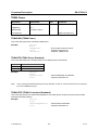
MEAS (Measurement Mode)
This command defines the measurement mode.
Value
0
1
2
3
4
5
6
7
8
9
10
11
Measurement
Off
Analyzer
Tracking Generator (Model 13, 23 and 26)
Power Sensor
Channel Power
Occupied Bandwidth
TDMA Power
Distance to Fault (R&S FSH-B1)
Receiver Mode (R&S FSH-K3)
Carrier / Noise
Isotropic Antenna
WCDMA BTS CDP
Using the value 0 the instrument can turned off if the power adapter is connected. If the instrument is
OFF it can be turned on programmatically by selecting one of the measurement modes.
Example:
set<cr>
0<cr>
meas,4<cr>
0<cr>
‘selects channel power measurement
‘responds parameter ok
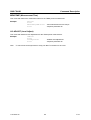
TRD1 (Transducer)
This command selects a transducer. To turn a transducer off, use the string ‘NONE’:
Example:
Example 2:
set<cr>
0<cr>
trd1,hl223<cr>
0<cr>
‘selects transducer table “HL223”
‘responds parameter ok
set<cr>
0<cr>
trd1,none<cr>
0<cr>
‘de-activates any transducer
‘responds parameter ok
TRD1X (Transducer X – dBµV/m)
This command selects an X-direction transducer (dBµV/m only) for the Isotropic Antenna
measurement. To turn a transducer off, use the string ‘NONE’:
Example:
Example 2:
1157.3564.12
set<cr>
0<cr>
trd1x,ts-emf-x<cr>
0<cr>
‘selects transducer table “TS-EMF-X”
‘responds parameter ok
set<cr>
0<cr>
trd1x,none<cr>
0<cr>
‘de-activates any transducer
‘responds parameter ok
46
E-10
R&S FSH-K1
Command Description
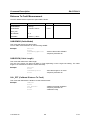
TRD1Y (Transducer Y – dBµV/m)
This command selects a Y-direction transducer (dBµV/m only) for the Isotropic Antenna measurement.
To turn a transducer off, use the string ‘NONE’:
Example:
Example 2:
set<cr>
0<cr>
trd1y,ts-emf-y<cr>
0<cr>
‘selects transducer table “TS-EMF-Y”
‘responds parameter ok
set<cr>
0<cr>
trd1y,none<cr>
0<cr>
‘de-activates any transducer
‘responds parameter ok
TRD1Z (Transducer Z – dBµV/m)
This command selects a Z-direction transducer (dBµV/m only) for the Isotropic Antenna measurement.
To turn a transducer off, use the string ‘NONE’:
Example:
Example 2:
set<cr>
0<cr>
trd1z,ts-emf-z<cr>
0<cr>
‘selects transducer table “TS-EMF-Z”
‘responds parameter ok
set<cr>
0<cr>
trd1z,none<cr>
0<cr>
‘de-activates any transducer
‘responds parameter ok
TRD2 (Transducer – dB )
This command selects a transducer (dB only). To turn a transducer off, use the string ‘NONE’.
Example:
set<cr>
0<cr>
trd1,preamp<cr>
0<cr>
‘selects transducer table “preamp”
‘responds parameter ok
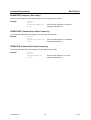
ACCESSORY (Connected Accessory)
This command gets or sets the connected accessory.
Value
0
1
2
3
4
5
Example:
1157.3564.12
Accessory
Auto Detect
None
Bridge R&S FSH-Z2
Bridge R&S FSH-Z3
Power sensor
Isotropic Antenna
set<cr>
0<cr>
accessory,0<cr>
0<cr>
‘Sets auto detection of accessory”
‘responds parameter ok
47
E-10
Command Description
R&S FSH-K1
LIMDEF (Define Limit Line)
This command defines a limit line.The list of parameters are the following:
<name>,<description>,<x-unit>,<x-scale>,<y-unit>,<x0>,<y0>[,...<xn>,<yn>]
The parameter <name> and <description> are strings. The parameters x-unit and y-unit are listed in the
tables below:
Parameter x-unit:
Value
0
1
2
Unit
Hz
Seconds
Meter
The parameter x-scale defines whether the x values are absolute values or relative values according to
the center x value:
Value
0
1
x-scale
Absolute
Relative
Parameter y-unit:
Value
0
1
2
3
4
5
6
7
8
9
10
11
12
13
Unit
dB
dBm
dBµV
dBmV
dBµV/m
dBµA/m
VSWR
Rho
Volt
Watt
Volt/m
2
Watt/m
Seconds
Degrees
The following example defines the limit line “LIMIT”, with description “Max” in dBm on the frequency
axis (Hz) as an absolute limit line with 4 values (100MHz -30dBm, 200MHz -10dBm, 300MHz -10dBm,
400MHz -30dBm):
Example:
Note:
set<cr>
0<cr>
limdef,LIMIT,Max,0,0,1,100e6,-30,200e6,-10,300e6,
-10,400e6,-30<cr>
‘defines limit line “LIMIT”
0<cr>
‘responds parameter ok
To replace an existing limit line in the instrument it has to be deleted first by using the LIMDEL
command described below.
1157.3564.12
48
E-10
R&S FSH-K1
Command Description
LIMDEL (Delete Limit Line)
This command deletes a limit line.
Example:
cmd<cr>
0<cr>
limdel,LIMIT<cr>
0<cr>
‘deletes limit line “LIMIT”
‘responds parameter ok
LIMLIST (Available Limit Line List)
This command returns the list with available limit lines
Example:
get<cr>
0<cr>
limlist<cr>
‘gets the limit line list
0<cr>
‘responds parameter ok
upper limit, lower limit, absolute limit<cr>
LIMLOW (Lower Limit Line)
This command selects the lower limit line. To turn a limit line off, use the string ‘NONE’.
Example:
set<cr>
0<cr>
limlow,lowtest<cr>
0<cr>
‘selects lower limit line “LOWTEST”
‘responds parameter ok
LIMUPP (Upper Limit Line)
This command selects the upper limit line. To turn a limit line off, use the string ‘NONE’.
Example:
set<cr>
0<cr>
limupp,hightest<cr>
0<cr>
‘selects upper limit line “HIGHTEST”
‘responds parameter ok
LIMPASS (Limits Passed Query)
This command returns the limit check status.
Value
0
1
2
Example:
1157.3564.12
Limit Check
Unkown
Failed
Passed
get<cr>
0<cr>
limpass<cr>
0<cr>
2<cr>
‘query limit check
‘responds parameter ok
‘limit check passed
49
E-10
Command Description
R&S FSH-K1
LIMCHKREMOTE (Limit Check Remote Message)
This command enables the remote message (frequency/channel + level) on limit check and/or on
threshold limit fail. The instrument will send a message (frequency/channel and level) every time the
limit is exceeded.
Value
0
1
Limit Check Remote
OFF
Limit Check – Remote message on
fail
Example:
get<cr>
0<cr>
limchkremote,1<cr>
0<cr>
123.456E6,23.5<cr>
130.567E6,22.0<cr>
…
0<cr>
‘enable remote massage on limit fail
‘responds parameter ok
‘limit exceeded
‘limit exceeded…..
‘remote message on limit fail OFF
LIMBEEP
This command turns the limit line beep on or off.
Value
0
1
Off
On
Example:
get<cr>
0<cr>
limbeep<cr>
0<cr>
1<cr>
‘query if limit line beep is switched on’
‘responds parameter ok’
‘limit beep is switched on’
LIMMSG
This command turns the limit line message on or off.
Value
0
1
Example:
1157.3564.12
Off
On
set<cr>
0<cr>
limmsg,1<cr>
0<cr>
‘switch limit line message on’
‘responds parameter ok’
50
E-10
R&S FSH-K1
Command Description
THRLOW (Lower Threshold Line)
This command defines the lower threshold line (value). The unit of the threshold value is specified with
the Unit parameter. This command is available in Receiver / Scan Mode only.
Example:
set<cr>
0<cr>
thrlow,30<cr>
0<cr>
‘specifies lower threshold line to -30 dBuV
‘responds parameter ok
THRUPP (Upper Threshold Line)
This command defines the upper threshold line (value). The unit of the threshold value is specified with
the Unit parameter. Available in Receiver / Scan Mode only.
Example:
set<cr>
0<cr>
thrupp,70<cr>
0<cr>
‘specifies upper threshold line to 70 dBuV
‘responds parameter ok
THRPASS (Threshold Line Passed Query)
This command returns the threshold line check status. Available in Receiver / Scan Mode only.
Value
0
1
2
Example:
1157.3564.12
Threshold Line Check
Unkown
Failed
Passed
get<cr>
0<cr>
thrpass<cr>
0<cr>
2<cr>
‘query threshold line check
‘responds parameter ok‘
‘threshold check passed
51
E-10
Command Description
R&S FSH-K1
Tracking Generator
This command set applies to model 13, model 23 and model 26 only.
Command
Parameters
Unit
CALKIT
[0…1]
CALKITLEN
<numeric value>
m
OFFSETLEN
<numeric value>
m
Comment
CAL_TGSCLRFL
CMD command only
CAL_TGSCLTRN
CMD command only
CAL_TGVECRFL
CMD command only
CAL_TGVECTRN
CMD command only
TRANSCAL
GET command only
REFLCAL
GET command only
TRANSVECTCAL
GET command only
Option R&S FSH-K2
REFLVECTCAL
GET command only
Option R&S FSH-K2
TGATT
<numeric value>
Model 23 & Model 26
(Serial No 100500 or higher)
TGLVL
<numeric value>
Model 23 only
TGMODE
[0…4]
Option R&S FSH-K2
CABLELOSS
GET command only
Option R&S FSH-K2
ELCABLENVAL
<numeric value>
VECTVOLT
< numeric value>
m / feet
GET command only
Option R&S FSH-K2
VVREF
VVTOREF
CMD command only
CALKIT
This command sets the tracking generator CalKit.
Value
0
1
Example:
1157.3564.12
Reflection Vector Cal
FSH Calkit
User CalKit
get<cr>
0<cr>
calkit<cr>
0<cr>
0<cr>
‘query the calkit
‘responds parameter ok
‘response: FSH CalKit selected
52
E-10
R&S FSH-K1
Command Description
CALKITLEN
This command defines the user calkit length. When set, also the user calkit will be selected. The
numeric values must be between 0 and 1 m with resolution of 0.01 mm.
Example:
set<cr>
0<cr>
calkitlen,1e-4<cr>
0<cr>
‘sets the user calkit length to 0.1 mm
‘responds parameter ok
OFFSETLEN
This command defines the offset length. The numeric values must be between 0 and 100 m with
resolution of 0.01 mm.
Example:
set<cr>
0<cr>
offsetlen,1<cr>
0<cr>
‘sets the offset length to 1 m
‘responds parameter ok
CAL_TGSCLRFL (Calibrate Tracking Generator Scalar Reflection)
This command initiates a scalar reflection calibration. This calibration contains two phases; OPEN
phase and SHORT phase. Connect OPEN before initiating calibration command, after first phase
reports ready connect SHORT and continue by issuing the command again.
Example:
cmd<cr>
0<cr>
cal_tgsclrfl<cr>
0<cr>
0<cr>
cal_tgsclrfl<cr>
0<cr>
0<cr>
‘initiate scalar reflection calibration (OPEN)
‘responds parameter ok
‘first phase ready
‘continue scalar reflection calibration (SHORT)
‘responds parameter ok
‘scalar reflection calibration ready
CAL_TGSCLTRN (Calibrate Tracking Generator Scalar Transmission)
This command initiates a scalar transmission calibration. This calibration contains one phase;
calibrating THROUGH. Connect THROUGH before initiating calibration command.
Example:
1157.3564.12
cmd<cr>
0<cr>
cal_tgscltrn<cr>
0<cr>
0<cr>
‘initiate scalar transmission calibration
‘responds parameter ok
‘scalar transmission calibration ready
53
E-10
Command Description
R&S FSH-K1
CAL_TGVECRFL (Calibrate Tracking Generator Vector Reflection)
This command initiates a vector reflection calibration. This calibration contains three phases; OPEN
phase, SHORT phase and a LOAD phase. Connect OPEN before initiating calibration command, after
first phase reports ready connect SHORT and continue by issuing the command again. When OPEN
calibration reports ready connect LOAD and resume calibration by issuing the command again.
Example:
cmd<cr>
0<cr>
cal_tgvecrfl<cr>
0<cr>
0<cr>
cal_tgsclrfl<cr>
0<cr>
0<cr>
cal_tgsclrfl<cr>
0<cr>
0<cr>
‘initiate vector reflection calibration (OPEN)
‘responds parameter ok
‘first phase ready
‘continue scalar reflection calibration (SHORT)
‘responds parameter ok
‘second phase ready
‘continue scalar reflection calibration (LOAD)
‘responds parameter ok
‘vector reflection calibration ready
CAL_TGVECTRN (Calibrate Tracking Generator Vector Transmission)
This command initiates a vector transmission calibration. This calibration contains two phases;
THROUGH phase and LOAD phase. Connect THROUGH before initiating calibration command, after
first phase reports ready connect LOAD and continue by issuing the command again.
Example:
cmd<cr>
0<cr>
cal_tgvectrn<cr>
0<cr>
0<cr>
cal_tgvectrn<cr>
0<cr>
0<cr>
‘initiate vector transmission calibration (THROUGH)
‘responds parameter ok
‘first phase ready
‘continue vector transmission calibration (LOAD)
‘responds parameter ok
‘vector transmission calibration ready
TRANSCAL (Transmission Calibrated)
This command queries the state of the transmission calibration.
Value
0
1
Example:
1157.3564.12
Transmission Cal
Not calibrated
Calibrated
get<cr>
0<cr>
transcal<cr>
0<cr>
1<cr>
‘query state of transmission calibration
‘responds parameter ok
‘response: transmission calibrated
54
E-10
R&S FSH-K1
Command Description
REFLCAL (Reflection Calibrated)
This command queries the state of the reflection calibration.
Value
0
1
Example:
Reflection Cal
Not calibrated
Calibrated
get<cr>
0<cr>
reflcal<cr>
0<cr>
1<cr>
‘query state of reflection calibration
‘responds parameter ok
‘response: reflection calibrated
TRANSVECTCAL (Transmission Vector Calibrated)
This command queries the state of the transmission vector calibration. Applies to option R&S FSH-K2
only.
Value
0
1
Example:
Transmission Vector Cal
Not calibrated
Calibrated
get<cr>
0<cr>
transvectcal<cr>
0<cr>
1<cr>
‘query state of transmission vector calibration
‘responds parameter ok
‘response: transmission vector calibrated
REFLVECTCAL (Reflection Vector Calibrated)
This command queries the state of the reflection vector calibration. Applies to option R&S FSH-K2 only
Value
0
1
Example:
Reflection Vector Cal
Not calibrated
Calibrated
get<cr>
0<cr>
reflvectcal<cr>
0<cr>
1<cr>
‘query state of reflection vector calibration
‘responds parameter ok
‘response: reflection vector calibrated
TGATT (Tracking Generator Level Attenuation)
This command defines the tracking generator output level attenuation. Applies to model 23 & 26 only.
The numeric values vary between 0 dB and 20 dB in 1 db steps.
Example:
1157.3564.12
set<cr>
0<cr>
tgatt,6<cr>
0<cr>
‘sets tracking generator attenuation to 6dB
‘responds parameter ok
55
E-10
Command Description
R&S FSH-K1
TGLVL (Tracking Generator Level)
This command defines the tracking generator output level. Applies to model 23 only.
The only two numeric values which are valid are 0 and –20.
Example:
Example 2:
set<cr>
0<cr>
tglvl,-20<cr>
0<cr>
‘sets tracking generator output level to –20 dBm
‘responds parameter ok
set<cr>
0<cr>
tglvl,0<cr>
0<cr>
‘sets tracking generator output level to 0 dBm
‘responds parameter ok
TGMODE (Tracking Generator Mode)
This command defines the tracking generator mode. Applies to option R&S FSH-K2 only. This
command is only available when Vector calibrated.
Value
0
1
2
3
4
5
Example:
Tracking Generator Mode
Magnitude
Cable loss meas
Phase
Smith Chart
Group Delay
Vector Voltage
set<cr>
0<cr>
tgmode, 1<cr>
0<cr>
‘set tracking generator mode to cable loss meas
‘responds parameter ok
CABLELOSS (Cable Loss)
This command queries the measured cable loss
Example:
1157.3564.12
get<cr>
0<cr>
cableloss<cr>
0<cr>
0.7<cr>
‘query cable loss measurement result
‘responds parameter ok
‘response: cable loss
56
E-10
R&S FSH-K1
Command Description
ELCABLENVAL (Electrical Cable Length)
This command queries the electrical cable length
Example:
Note:
get<cr>
0<cr>
elcablenval<cr>
0<cr>
5.12<cr>
‘query electrical cable length measurement result
‘responds parameter ok
‘response: electrical cable length
This command is only available when measurement mode is Phase and zero span is not active.
VECTVOLT (Vector Voltage)
This command queries the measured vector voltage values.
Example:
get<cr>
0<cr>
vectvolt<cr>
0<cr>
3.0,45<cr>
‘query vector voltage measurement result
‘responds parameter ok
‘response: magnitude (dB), phase (degrees)
VVREF (Vector Voltage Reference)
This command queries the vector voltage reference values. To disable the vector voltage reference set
it to 0.
Example 1:
Example 2:
get<cr>
0<cr>
vvref<cr>
0<cr>
3.0,45<cr>
‘query vector voltage reference
‘responds parameter ok
‘response: magnitude (dB), phase (degrees)
set<cr>
0<cr>
vvref,0<cr>
0<cr>
‘disable vector voltage reference
‘responds parameter ok
VVTOREF (Vector Voltage To Reference)
This command will set the current vector voltage values as vector voltage reference. To disable the
vector voltage reference use VECTVOLTREF.
Example get:
1157.3564.12
cmd<cr>
0<cr>
vvtoref<cr>
0<cr>
‘set vector voltage reference
‘responds parameter ok
57
E-10
Command Description
R&S FSH-K1
Power Sensor
Command
Parameters
PWR
REFL
ZERO
PWRTOREF
MEASTIME
REFLUNIT
PWRSSTD
<numeric value>
<numeric value>
Unit
Comment
GET command only
GET command only
CMD command only
CMD command only
0...2
0, 1
0…7
R&S FSH-Z44 only
R&S FSH-Z44 only
PWR (Power Level)
This command queries the power level measured by the sensor.
Example:
get<cr>
0<cr>
pwr<cr>
0<cr>
-33.45<cr>
‘query power level from sensor
‘responds parameter ok
‘response: power
REFL (Reflection)
This command queries the reflection measured by the power sensor R&S FSH-Z44. The unit (dB or
VSWR ) depends on the setting of reflection unit (SET REFLUNIT command).
Example:
get<cr>
0<cr>
refl<cr>
0<cr>
2.54<cr>
‘query reflection from sensor
‘responds parameter ok
‘response: reflection value
ZERO (Power Sensor Zeroing)
This command initiates the power sensor zeroing.
Example:
cmd<cr>
0<cr>
zero<cr>
0<cr>
‘query power level from sensor
‘responds parameter ok
PWRTOREF (Power to Reference)
This command defines the current power level as the reference value.
Example:
1157.3564.12
cmd<cr>
0<cr>
pwrtoref<cr>
0<cr>
‘defines power level as reference value
‘responds parameter ok
58
E-10
R&S FSH-K1
Command Description
MEASTIME (Measurement Time)
This command defines the measurement time for the power sensor (R&S FSH-Z1 and R&S FSH-Z18).
Value
0
1
2
Example:
Measurement Time
Short
Normal
Long
set<cr>
0<cr>
meastime,2<cr>
0<cr>
‘sets measurement time to “long”
‘responds parameter ok
REFLUNIT (Reflection Unit)
This command defines the reflection unit for the power sensor R&S FSH-Z44.
Value
0
1
Example:
Reflection Unit
dB
VSWR
set<cr>
0<cr>
reflunit,1<cr>
0<cr>
‘sets reflection unit to VSWR
‘responds parameter ok
PWRSSTD (Power Sensor Standard)
This command defines the standard used for the power sensor R&S FSH-Z44 measurements.
Value
0
1
2
3
4
5
6
7
Example:
1157.3564.12
Channel Power Standard
User
GSM
EDGE
3GPP WCDMA
cdmaOne
cdma2000 1x
DVB-T
DAB
set<cr>
0<cr>
pwrsstd,2<cr>
0<cr>
‘select EDGE as standard
‘responds parameter ok
59
E-10
Command Description
R&S FSH-K1
Channel Power
Command
Parameters
CHPWR
CHPWRSTD
CHPWRCSTD
CHPWRUNIT
CHPWRBW
LVLADJUST
<numeric value>
0…3
<string>
0…2
<numeric value>
Unit
Comment
GET command only
Hz
CMD command only
CHPWR (Channel Power)
This command queries the measured channel power.
Example:
get<cr>
0<cr>
chpwr<cr>
0<cr>
-47.45<cr>
‘query power level from sensor
‘responds parameter ok
‘response: channel power
CHPWRSTD (Channel Power Standard)
This command defines the standard used for the channel power measurement.
Value
0
1
2
3
Example:
Note:
Channel Power Standard
User
3GPP WCDMA
cdmaOne
cdma2000 1x
set<cr>
0<cr>
chpwrstd,2<cr>
0<cr>
‘select cdmaOne as standard
‘responds parameter ok
If any customized standard was previously selected a value of ‘4’ will be returned as a response
to a GET CHPWRSTD query.
CHPWRCSTD (Channel Power Customized Standard)
This command selects the customized standard for the channel power measurement previously loaded
with R&S FSHView software.
Example:
1157.3564.12
set<cr>
0<cr>
chpwrcstd,MyStd<cr>
0<cr>
60
‘select MyStd as standard
‘responds parameter ok
E-10
R&S FSH-K1
Command Description
CHPWRUNIT (Channel Power Unit)
This command defines the unit used for the channel power measurement.
Value
0
1
2
Example:
Channel Power Unit
dBm
dBmV
dB\V
set<cr>
0<cr>
chpwrunit,1<cr>
0<cr>
‘set unit to dBmV
‘responds parameter ok
CHPWRBW (Channel Power Bandwidth)
This command defines the bandwidth used for channel power measurements.
Example:
set<cr>
0<cr>
chpwrbw,3.5E6<cr>
0<cr>
‘set channel power bandwidth to 3.5 MHz
‘responds parameter ok
LVLADJUST (Level Adjust)
This command initiates a level adjustment for the channel power measurement.
Example:
Note:
cmd<cr>
0<cr>
lvladjust<cr>
0<cr>
‘initiates level adjustment
‘responds parameter ok
To check if the level adjustment is ready, the WAIT command can be used
1157.3564.12
61
E-10
Command Description
R&S FSH-K1
Occupied Bandwidth
Command
Parameters
OBW
OBWSTD
OBWCSTD
OBWCHBW
LVLADJUST
<numeric value>
0…3
<string>
<numeric value>
Unit
Comment
GET command only
Hz
CMD command only
OBW (Occupied Bandwidth)
This command queries the measured occupied bandwidth.
Example:
get<cr>
0<cr>
obw<cr>
0<cr>
-22E6<cr>
‘query power level from sensor
‘responds parameter ok
‘response: occupied bandwidth
OBWSTD (Occupied Bandwidth Standard)
This command defines the standard used for the occupied bandwidth measurement.
Value
0
1
2
3
Example:
Note:
Occupied Bandwidth Standard
User
3GPP WCDMA
cdmaOne
cdma2000 1x
set<cr>
0<cr>
obwstd,1<cr>
0<cr>
‘select 3GPP WCDMA as standard
‘responds parameter ok
If any customized standard was previously selected a value of ‘4’ will be returned as a response
to a GET OBWSTD query.
OBWCSTD (Occupied Bandwidth Customized Standard)
This command selects the customized standard for the occupied bandwidth measurement previously
loaded with R&S FSHView software.
Example:
1157.3564.12
set<cr>
0<cr>
obwcstd,MyStd<cr>
0<cr>
‘select MyStd as standard
‘responds parameter ok
62
E-10
R&S FSH-K1
Command Description
OBWCHBW (Occupied Bandwidth Channel Bandwidth)
This command defines the bandwidth used for occupied bandwidth measurements.
Example:
set<cr>
0<cr>
obwchbw,5E6<cr>
0<cr>
‘set channel bandwidth to 5 MHz
‘responds parameter ok
LVLADJUST (Level Adjust)
This command initiates a level adjustment for the occupied bandwidth measurement.
Example:
Note:
cmd<cr>
0<cr>
lvladjust<cr>
0<cr>
‘initiates level adjustment
‘responds parameter ok
To check if the level adjustment is ready, the WAIT command can be used
1157.3564.12
63
E-10
Command Description
R&S FSH-K1
TDMA Power
Command
Parameters
TDMAPWR
<numeric value>
TDMASTD
0…1
MEASTIME
<numeric value>
Unit
Comment
GET command only
s
LVLADJUST
CMD command only
TDMAPWR (TDMA Power)
This command queries the measured TDMA power.
Example:
get<cr>
0<cr>
tdmapwr<cr>
0<cr>
-32.45<cr>
‘query power level from sensor
‘responds parameter ok
‘response: TDMA power
TDMASTD (TDMA Power Standard)
This command defines the standard used for the TDMA power measurement.
Value
TDMA Power Standard
0
1
User
GSM / EDGE
Example:
Note:
set<cr>
0<cr>
tdmastd,1<cr>
0<cr>
‘select GSM/EDGE as standard
‘responds parameter ok
If any customized standard was previously selected a value of ‘2’ will be returned as a response
to a GET TDMASTD query.
TDMACSTD (TDMA Customized Standard)
This command selects the customized standard for the TDMA power measurement previously loaded
with R&S FSHView software.
Example:
1157.3564.12
set<cr>
0<cr>
tdmacstd,MyStd<cr>
0<cr>
‘select MyStd as standard
‘responds parameter ok
64
E-10
R&S FSH-K1
Command Description
MEASTIME (Measurement Time)
This command defines the measurement time for the TDMA power measurement.
Example:
set<cr>
0<cr>
meastime,500E-6<cr>
0<cr>
‘sets measurement time to 500 \s
‘responds parameter ok
LVLADJUST (Level Adjust)
This command initiates a level adjustment for the TDMA power measurement.
Example:
Note:
cmd<cr>
0<cr>
lvladjust<cr>
0<cr>
‘initiates level adjustment
‘responds parameter ok
To check if the level adjustment is ready, the WAIT command can be used
1157.3564.12
65
E-10
Command Description
R&S FSH-K1
Distance To Fault Measurement
The DTF Measurement requires the option R&S FSH-B1.
Command
Parameters
CABLEMOD
<string>
CABLELEN
<numeric value>
Unit
Comment
m / feet
CAL_DTF
DTFMODE
0...2
LENUNIT
<meter> | <feet>
CABLEMOD (Cable Model)
This command selects the cable model.
To turn cable model selection off, use the string ‘NONE’.
Example:
set<cr>
0<cr>
cablemod,rg58c<cr>
0<cr>
‘selects cable model “RG58C”
‘responds parameter ok
CABLELEN (Cable Length)
This command defines the cable length.
The unit of the length can either be Meter or Feet depending on the Length Unit setting. The cable
length is converted and rounded to meters internally.
Example:
set<cr>
0<cr>
cablelen,12<cr>
0<cr>
‘sets cable length to 12 meter
‘responds parameter ok
CAL_DTF (Calibrate Distance To Fault)
This command calibrates the distance to fault measurement.
Example:
1157.3564.12
cmd<cr>
0<cr>
cal_dtf<cr>
0<cr>
0<cr>
‘Initiates the actual calibration
‘responds parameter ok
‘calibration ready
66
E-10
R&S FSH-K1
Command Description
DTFMODE (DTF Measurement Mode) Power)
This command defines the measurement mode in DTF.
Value
0
1
2
Example:
Channel Power Standard
DTF
Reflection
Spectrum
set<cr>
0<cr>
dtfmode,2<cr>
0<cr>
‘set DTF mode to “Spectrum”
‘responds parameter ok
LENUNIT (Cable Length Unit)
This command sets the cable length unit to meters or feet.
Example:
1157.3564.12
set<cr>
0<cr>
lenunit,feet<cr>
0<cr>
‘sets cable length unit to Feet
‘responds parameter ok
67
E-10
Command Description
R&S FSH-K1
Receiver Mode
The Receiver Mode requires the option R&S FSH-K3.
Command
Parameters
CHANNEL
<numeric value>
CHMODE
0, 1
CHTABLE
<string>
Unit
Comment
Fixed Channel Mode
LEVEL
GET command only
MEASTIME
<numeric value>
s
SCANMODE
0, 1
SCANSTART
<numeric value>
Freq Scan Mode
SCANSTOP
<numeric value>
Freq Scan Mode
SCANSTEP
<numeric value>
Freq Scan Mode
FREQSTART
<numeric value>
Channel Scan Mode
FREQSTOP
<numeric value>
Channel Scan Mode
CHMODE (Channel Mode)
This command switches between the channel mode and frequency mode. Use the command
CHTABLE to define a channel table for the channel mode.
Value
0
1
Example:
Channel Mode
Frequency Mode
Channel Mode
set<cr>
0<cr>
chmode,1<cr>
0<cr>
‘selects channel mode
‘responds parameter ok
CHANNEL (Channel Number)
This command defines the channel number. Use CHTABLE command to select a channel table first.
Example:
set<cr>
0<cr>
channel,55<cr>
‘selects channel no. 55
CHTABLE (Channel Table)
This command selects a channel table for the channel mode.
Example:
1157.3564.12
set<cr>
0<cr>
chtable,FMBand<cr>
0<cr>
‘selects channel table “FMBand”
‘responds parameter ok
68
E-10
R&S FSH-K1
Command Description
LEVEL (Signal Level)
This command queries the signal level measured (fixed frequency/channel mode only).
Example:
get<cr>
0<cr>
level<cr>
0<cr>
45.6<cr>
‘query signal level
‘responds parameter ok
‘response: signal level
MEASTIME (Measurement Time)
This command defines the measurement time for the receiver mode.
Example:
set<cr>
0<cr>
meastime,5E-3<cr>
0<cr>
‘sets measurement time to 5 ms
‘responds parameter ok
SCANMODE (Scan Mode)
This command switches between frequency/channel scan mode and fixed frequency/channel mode.
Use the command CHMODE to toggle between frequency and channel mode.
Value
0
1
Example:
Scan Mode
Fixed Freq/Channel Mode
Feq/Channel Scan Mode
set<cr>
0<cr>
scanmode,1<cr>
0<cr>
‘selects scan mode
‘responds parameter ok
SCANSTART (Frequency Scan Start)
This command defines the scan start frequency for the frequency scan mode.
Example:
set<cr>
0<cr>
scanstart,88E6<cr>
0<cr>
‘sets scan start frequency to 88 MHz
‘responds parameter ok
SCANSTOP (Frequency Scan Stop)
This command defines the scan stop frequency for the frequency scan mode.
Example:
1157.3564.12
set<cr>
0<cr>
scanstop,108E6<cr>
0<cr>
‘sets scan stop frequency to 108 MHz
‘responds parameter ok
69
E-10
Command Description
R&S FSH-K1
SCANSTEP (Frequency Scan Step)
This command defines the scan step frequency for the frequency scan mode.
Example:
set<cr>
0<cr>
scanstep,200E3<cr>
0<cr>
‘sets scan step frequency to 200 kHz
‘responds parameter ok
FREQSTART (Channel Scan Start Frequency)
This command defines the start frequency for the channel scan mode.
Example:
set<cr>
0<cr>
freqstart,100E6<cr>
0<cr>
‘sets scan start frequency to 100 MHz
‘responds parameter ok
FREQSTOP (Channel Scan Stop Frequency)
This command defines the stop frequency for the channel scan mode.
Example:
1157.3564.12
set<cr>
0<cr>
freqstop,1E9<cr>
0<cr>
‘sets scan stop frequency to 1 GHz
‘responds parameter ok
70
E-10
R&S FSH-K1
Command Description
Carrier / Noise Measurement
Command
Parameters
Unit
CNCHBW
<numeric value>
Hz
CNCSTD
<string>
CNMANREFPWR
0, 1
CNMEASMODE
0...2
CNMODE
0, 1
CNNOISECOR
0, 1
CNNORM
0, 1
CNPILOTFRQ
<numeric value>
CNPWRDISP
0, 1
CNRATIOCHBW
<numeric value>
CNREFMEASMODE
0, 1, 2
CNREFPWR
<numeric value>
CNUNIT
0...2
Hz
Hz
CNVALUE
CNVISIONFRQ
Comment
GET command only
<numeric value>
Hz
LVLADJUST
CMD command only
CNCHBW (Carrier Noise Channel Bandwidth)
This command defines the bandwidth used for carrier noise measurements. It defines the channel
bandwidth of the reference measurement if the C/N reference measurement is selected and it defines
the channel bandwidth of the noise measurement if the C/N noise measurement is selected. The
measurement mode is selected by the command CNMODE.
Example:
1157.3564.12
set<cr>
0<cr>
cnchbw,5E6<cr>
0<cr>
‘set channel bandwidth to 5 MHz
‘responds parameter ok
71
E-10
Command Description
R&S FSH-K1
CNCSTD (Carrier Noise Customized Standard)
This command selects the customized standard for the carrier noise measurement previously loaded
with R&S FSHView software.
Example:
set<cr>
0<cr>
cncstd,MyStd<cr>
0<cr>
‘select MyStd as standard
‘responds parameter ok
CNMANREFPWR (Carrier Noise Manual Ref Power Active)
This command defines if the manual ref power is active. If the manual reference power is selected a
reference power must be set (CNREFPWR). Otherwise the reference power of the reference power
measurement is applied.
Value
0
1
Manual Ref Power Active
OFF
ON
Example:
set<cr>
0<cr>
cnmanrefpwr,1<cr>
0<cr>
‘select manual reference power
‘responds parameter ok
CNMEASMODE (Carrier Noise Measurement Mode)
This command defines the kind of reference measurement mode if the reference measurement mode is
selected. It is used for the carrier noise measurement.
Value
0
1
2
Measurement Mode
Digital Tx
Analog TV
CW Tx
Example:
set<cr>
0<cr>
cnmeasmode,1<cr>
0<cr>
‘select Analog TV as measurement mode
‘responds parameter ok
CNMODE (Carrier Noise Mode)
This command defines if the C/N reference measurement or the C/N noise measurement is active.
Value
0
1
Example:
1157.3564.12
C/N Noise Measurement Active
OFF
ON
set<cr>
0<cr>
cnmode,0<cr>
0<cr>
‘select C/N reference measurement
‘responds parameter ok
72
E-10
R&S FSH-K1
Command Description
CNNOISECOR (Carrier Noise NOISE CORrection)
This command defines if the C/N noise correction mode.
Value
0
1
C/N Noise Correction
OFF
ON
Example:
set<cr>
0<cr>
cnnoisecor,0<cr>
0<cr>
‘disable C/N noise correction
‘responds parameter ok
CNNORM (Carrier Noise Norm)
This command defines the norm used for the noise measurement.
Value
Norm
0
1
C/N
C/No
Example:
set<cr>
0<cr>
cnnorm,1<cr>
0<cr>
‘select C/No as norm
‘responds parameter ok
CNPILOTFRQ (Carrier Noise Pilot Frequency)
This command defines the pilot frequency used for digital TV carrier noise measurements. It is only
available if the Digital TV standard 8-VSB/ATSC is selected. It defines the pilot frequency of the
reference measurement if the C/N reference measurement is selected and it defines the pilot frequency
of the noise measurement if the C/N noise measurement is selected. The measurement mode is
selected by the command CNMODE.
Example:
1157.3564.12
set<cr>
0<cr>
cnpilotfrq,450E6<cr> ‘set pilot frequency to 450 MHz
0<cr>
‘responds parameter ok
73
E-10
Command Description
R&S FSH-K1
CNPWRDISP (Carrier Noise Power Display)
This command turns the C/N power display on or off.
Value
0
1
Example:
Power Display
OFF
ON
set<cr>
0<cr>
cnpwrdisp,1<cr>
0<cr>
‘responds parameter ok
CNRATIOCHBW (Carrier Noise Ratio Channel Bandwidth)
This command defines the ratio channel bandwidth used for carrier noise measurements.
Example:
set<cr>
0<cr>
cnratiochbw,5E6<cr>
0<cr>
‘set ratio channel bandwidth to 5 MHz
‘responds parameter ok
CNREFMEASMODE (Carrier Noise Reference measurement mode)
This command sets the reference measurement mode.
Value
0
1
2
Example:
Reference Measurement Mode
Peak Power
Channel Power
Manual
set<cr>
0<cr>
cnrefmeasmode,2<cr>
0<cr>
‘set reference measurement mode to manual
‘responds parameter ok
CNREFPWR (Carrier Noise Ref Power)
This command defines the reference power used for carrier noise measurements.
Example:
1157.3564.12
set<cr>
0<cr>
cnrefpwr,400E-3<cr>
0<cr>
74
‘set ref power to 0.4
‘responds parameter ok
E-10
R&S FSH-K1
Command Description
CNUNIT (Carrier Noise Unit)
This command defines the unit used for the reference.
Value
0
1
2
Unit
dBm
dBmV
dBuV
Example:
set<cr>
0<cr>
cnunit,1<cr>
0<cr>
‘select dBmV as unit
‘responds parameter ok
CNVALUE (Carrier Noise Measurement Value)
This command queries the measured C/N value. The value depends on the CNMODE selected (either
C/N reference measurement or C/N Noise measurement).
Example:
get<cr>
0<cr>
cnvalue<cr>
0<cr>
-20.3<cr>
‘query C/N measurement
‘responds parameter ok
‘response: C/N result
CNVISIONFRQ (Carrier Noise Vision Frequency)
This command defines the vision carrier frequency used for analog TV carrier noise measurements.
Example:
set<cr>
0<cr>
cnvisionfrq,450E6<cr> ‘set vision carrier frequency to 450 MHz
0<cr>
‘responds parameter ok
LVLADJUST (Level Adjust)
This command initiates a level adjustment for carrier noise measurement. It is applied to the reference
channel if the reference measurement is selected and it is applied to the noise channel if the noise
measurement is selected.
Example:
Note:
cmd<cr>
0<cr>
lvladjust<cr>
0<cr>
‘initiates level adjustment
‘responds parameter ok
To check if the level adjustment is ready, the WAIT command can be used
1157.3564.12
75
E-10
Command Description
R&S FSH-K1
WCDMA BTS CDP Measurement
The WCDMA Measurement requires the option R&S FSH-K4.
Command
Parameters
ANTDIV
<numeric value>
CARRFREQERR
CPICHPWR
<1…6>
Unit
Comment
Hz
GET command only
dBm
CPICHSLOTNR
GET command only
CPICHSYMEVM
% rms
GET command only
PCCPCHPWR
dBm
GET command only
PCCPCHPWRREL
dB
GET command only
PCCPCHSYMEVM
% rms
GET command only
PSCHPWR
dBm
GET command only
PSCHPWRREL
dB
GET command only
SSCHPWR
dBm
GET command only
SSCHPWRREL
dB
GET command only
PSCRCD
SSCRCD
<1…6>,<numeric value>
<1…6>,<numeric value>
SYNCRESULT
GET command only
TOTPWR
dBm
GET command only
AUTOSDSNGL
CMD command only
AUTOSDMUL
CMD command only
CPICHEIRAT
dB
GET command only
PCCPCHEIRAT
dB
GET command only
1157.3564.12
76
E-10
R&S FSH-K1
Command Description
ANTDIV (Antenna diversity)
This command defines the antenna diversity mode used for WCDMA measurements.
Value
Antenna Diversity Mode
0
1
2
Antenna Div. mode OFF
Antenna Div. mode no. 1
Antenna Div. mode no. 2
Example:
set<cr>
0<cr>
antdiv,1<cr>
0<cr>
‘set antenna diversity to type No. 1
‘responds parameter ok
CARRFREQERR (Carrier Frequency Error)
This command retrieves the carrier frequency error for WCDMA measurements. Unit is Hz.
Example:
get<cr>
0<cr>
carrfreqerr<cr> ‘get carrier frequency error
0<cr>
‘responds parameter ok
0<cr>
‘Carrier frequency error is zero Hz
CPICHPWR (CPICH Power)
This command retrieves the P-CPICH Power measurement result for WCDMA measurements. Unit is
the current unit.
Optional Value
1…6
Example:
Scrambling Code id
id 1…6
get<cr>
0<cr>
cpichpwr<cr>
0<cr>
-9.5<cr>
‘get CPICH power of scrambling code nr id 1
‘responds parameter ok
‘CPICH power is -9.5 dBm
If an auto scrambling detection multiple has been performed successfully the command allows an
option parameter.
Example:
get<cr>
0<cr>
cpichpwr,4<cr>
0<cr>
13<cr>
‘get CPICH Power of scrambling code id 4
‘responds parameter ok
‘CPICH Power is 13 dBm
CPICHSLOTNR (CPICH Slot Number)
This command retrieves the CPI slot number for WCDMA measurements.
Example:
1157.3564.12
get<cr>
0<cr>
cpichslotnr<cr> ‘get CPICH Slot Number
0<cr>
‘responds parameter ok
0<cr>
‘CPICH slot number is ‘0’
77
E-10
Command Description
R&S FSH-K1
CPICHSYMEVM (CPICH Symbol EVM)
This command retrieves the P-CPICH Symbol EVM measurement result for WCDMA measurements.
Unit is % rms.
Example:
get<cr>
0<cr>
cpichsymevm<cr> ‘get CPICH Symbol EVM
0<cr>
‘responds parameter ok
23<cr>
‘CPICH Symbol EVM is 23 % rms
PCCPCHPWR (P-CCPCH Power)
This command retrieves the P-CCPCH Power measurement result for WCDMA measurements. Unit is
the current unit.
Example:
get<cr>
0<cr>
pccpchpwr<cr>
0<cr>
-26.8<cr>
‘get P-CCPCH Power
‘responds parameter ok
‘P-CCPCH Power is -26.8 dBm
PCCPCHPWRREL (P-CCPCH Power relative to CPICH)
This command retrieves the P-CCPCH Power relative to the CPICH Power measurement result for
WCDMA measurements. Unit is in dB.
Example:
get<cr>
0<cr>
pccpchpwrrel<cr> ‘get P-CCPCH Power relative to CPICH
0<cr>
‘responds parameter ok
-2.8<cr>
‘P-CCPCH Power is -2.8 dB lower then CPICH Power
PCCPCHSYMEVM (P-CCPCH Symbol EVM)
This command retrieves the P-CCPCH Symbol EVM measurement result for WCDMA measurements.
Unit is % rms.
Example:
get<cr>
0<cr>
pccpchsymevm<cr> ‘get P-CCPCH Symbol EVM
0<cr>
‘responds parameter ok
63.9<cr>
‘P-CCPCH Symbol EVM is 63.9 % rms
PSCHPWR (P-SCH Power)
This command retrieves the P-SCH Power measurement result for WCDMA measurements. Unit is the
current unit
Example:
1157.3564.12
get<cr>
0<cr>
pschpwr<cr>
0<cr>
13<cr>
‘get P-SCH Power
‘responds parameter ok
‘P-SCH Power is 13 dBm
78
E-10
R&S FSH-K1
Command Description
PSCHPWRREL (P-SCH Power relative to CPICH)
This command retrieves the P-SCH Power relative to CPICH measurement result for WCDMA
measurements. Unit is in dB
Example:
get<cr>
0<cr>
pschpwrrel<cr>
0<cr>
3.2<cr>
‘get P-SCH Power relative to CPICH
‘responds parameter ok
‘P-SCH Power is 3.2 dB higher then CPICH
PSCRCD (Primary Scramble Code)
This command defines the primary part of the scrambling code. The scrambling code is divided into 2
parts, a primary and a secondary part.
Valid input for primary scrambling code varies from 0 to 1535 (0x00 – 0x600-1). From the primary and
secondary scrambling codes the common scrambling code can be calculated as follows.
ScrBS = Scrprimary 16 + Scrsec ondary
Example:
set<cr>
0<cr>
pscrcd,123<cr>
0<cr>
‘set prim. scramb. code to 123
‘responds parameter ok
If an auto scrambling detection multiple has been performed successfully the get command allows an
option parameter.
Optional Value
1…6
Example:
Scrambling Code id
id 1…6
get<cr>
0<cr>
pscrcd,4<cr>
0<cr>
1<cr>
‘get prim scrambling code of id 4
‘responds parameter ok
‘prim scambling code number is 1
SSCHPWR (S-SCH Power)
This command retrieves the S-SCH Power measurement result for WCDMA measurements. Unit is the
current unit.
Example:
get<cr>
0<cr>
sschpwr<cr>
0<cr>
-87.1<cr>
‘get S-SCH Power
‘responds parameter ok
‘S-SCH Power is -87.1 dBm
SSCHPWRREL (S-SCH Power relative to CPICH)
This command retrieves the S-SCH Power relative to CPICH measurement result for WCDMA
measurements. Unit is dB.
Example:
1157.3564.12
get<cr>
0<cr>
sschpwrrel<cr>
0<cr>
-7.1<cr>
‘get S-SCH Power relative to CPICH
‘responds parameter ok
‘S-SCH Power is -7.1 dB lower then CPICH
79
E-10
Command Description
R&S FSH-K1
SSCRCD (Secondary Scramble Code)
This command defines the secondary part of the scrambling code. The scrambling code is divided into
2 parts, a primary and a secondary part.
Valid input for secondary code varies from 0 to 15 (0x0 – 0x10-1). From the primary and secondary
scrambling codes the common scrambling code can be calculated as follows:
ScrBS = Scrprimary 16 + Scrsec ondary
Example:
set<cr>
0<cr>
sscrcd,8<cr>
0<cr>
‘set sec. scrambling code nr to 8
‘responds parameter ok
If an auto scrambling detection multiple has been performed successfully the get command allows an
option parameter.
Optional Value
1…6
Example:
Scrambling Code id
id 1…6
get<cr>
0<cr>
sscrcd,4<cr>
0<cr>
0<cr>
‘get sec scrambling code nr of id 4
‘responds parameter ok
‘sec scambling code number is 0
SYNCRESULT (Synchronization result)
This command retrieves the synchronization result for the WDMA measurement.
Value
0
1
2
3
4
5
Example:
1157.3564.12
Synchronization result
Synchronization OK
Invalid synchronization
Incorrect antenna diversity setting
Incorrect sent CPICH symbols
Incorrect center frequency
Incorrect primary or secondary scrambling code
get<cr>
0<cr>
syncresult<cr>
0<cr>
2<cr>
‘get synchronization result
‘responds parameter ok
‘sync. result: SYNC_RESULT_INCORR_ANTENNA_DIV
80
E-10
R&S FSH-K1
Command Description
TOTPWR (Total Power)
This command retrieves the total power measurement result for WCDMA measurements. Unit is the
current unit.
Example:
get<cr>
0<cr>
totpwr<cr>
0<cr>
-87<cr>
‘get total power
‘responds parameter ok
‘Total power is -87 dBm
AUTOSDSNGL (Auto Scrambling Detection Single)
This command starts the auto scrambling detection single.
Example:
cmd<cr>
0<cr>
autosdsngl<cr>
0<cr>
‘start auto scrambling detection single
‘responds parameter ok
AUTOSDMUL (Auto Scrambling Detection Multiple)
This command starts the auto scrambling detection multiple.
Example:
cmd<cr>
0<cr>
autosdsngl<cr>
0<cr>
‘start auto scrambling detection multiple
‘responds parameter ok
CPICHEIRAT (P-CPICH Ec/Io)
This command retrieves the CPICH Ec/Io measurement result for WCDMA measurements. Unit is dB.
Example:
get<cr>
0<cr>
cpicheirat<cr>
0<cr>
-26.8<cr>
‘get CPICH Ec/Io
‘responds parameter ok
‘CPICH Ec/Io is -26.8 dB
PCCPCHEIRAT (P-CCPCH Ec/Io)
This command retrieves the P-CCPCH Ec/Io measurement result for WCDMA measurements. Unit is
dB.
Example:
1157.3564.12
get<cr>
0<cr>
pccpcheirat<cr> ‘get P-CCPCH Ec/Io
0<cr>
‘responds parameter ok
-26.8<cr>
‘P-CCPCH Ec/Io is -26.8 dB
81
E-10
Programming Examples
R&S FSH-K1
Programming Examples
The following examples are code snippets in Visual Basic (VB6).
Initialize Communication with R&S FSH
Public Function FSHInit(ByVal Port As Integer, ByVal Speed As Long,
Optional ByVal ErrorCode As String) As Boolean
Rem Initialize communication with FSH
Rem Return TRUE if device initialization was successful
Rem Return FALSE otherwise e.g. the device was not found
With MainForm.FSHCommC
.CommPort = Port
.Settings = Trim$(Str$(Speed)) + ",N,8,1"
.InBufferSize = 1000
.PortOpen = True
.InBufferCount = 0
End With
InBuffer = vbNullString
End Function
‘-------------------------------------------
Poll R&S FSH until <cr> received
Public Function PollFSH() As String
Dim CrPos As Long
With MainForm.FSHCommC
Do
InBuffer = InBuffer + .Input
DoEvents
CrPos = InStr(1, InBuffer, vbCr)
Loop Until CrPos > 0
PollFSH = Left$(InBuffer, CrPos - 1)
InBuffer = Mid$(InBuffer, CrPos + 1)
End With
End Function
‘-------------------------------------------
Send CMD Command to R&S FSH
Public Function FSHCmd(ByVal Command As String) As Boolean
Dim TempError As Integer
InBuffer = vbNullString
FSHCmd = False
With MainForm.FSHCommC
.Output = "cmd" + vbCr
TempError = Val(PollFSH)
If TempError = 0 Then
.Output = Command + vbCr
TempError = Val(PollFSH)
If TempError = 0 Then
FSHCmd = True
Else
DebugMsg "CMD error" + Str(TempError) + " for command <" + Command + ">"
End If
Else
DebugMsg "CMD error" + Str(TempError) + " for command <" + Command + ">"
End If
End With
End Function
‘-------------------------------------------
1157.3564.12
82
E-10
R&S FSH-K1
Programming Examples
Send SET Command to R&S FSH
Public Function FSHSet(ByVal Command As String) As Boolean
Dim TempError As Integer
InBuffer = vbNullString
FSHSet = False
With MainForm.FSHCommC
.Output = "set" + vbCr
TempError = Val(PollFSH)
If TempError = 0 Then
.Output = Command + vbCr
TempError = Val(PollFSH)
If TempError = 0 Then
FSHSet = True
Else
ErrorMsg "SET error" + Str(TempError) + " for command <" + Command + ">"
End If
Else
ErrorMsg "SET error" + Str(TempError) + " for command <" + Command + ">"
End If
End With
End Function
‘-------------------------------------------
Send GET Command to R&S FSH and Read Response
Public Function FSHGet(ByVal Command As String, ByRef Buffer As String) As Boolean
Dim TempError As Integer
InBuffer = vbNullString
FSHGet = False
With MainForm.FSHCommC
.Output = "get" + vbCr
TempError = Val(PollFSH)
If TempError = 0 Then
.Output = Command + vbCr
TempError = Val(PollFSH)
If TempError = 0 Then
Sleep 50
Buffer = PollFSH
FSHGet = True
Else
ErrorMsg "GET error" + Str(TempError) + " for command <" + Command + ">"
End If
Else
ErrorMsg "GET error" + Str(TempError) + " for command <" + Command + ">"
End If
End With
End Function
‘-------------------------------------------
Example: Program Instrument Setup
Private Sub FSHSetup ()
Dim Buffer As String
FSHCmd
FSHGet
FSHCmd
FSHSet
FSHSet
FSHCmd
"REMOTE"
"IDN?", Buffer
"PRESET"
"FREQ,950E6"
"SPAN,5E6"
"LOCAL"
‘
‘
‘
‘
‘
‘
Set FSH to Remote State
Query instrument ID
Preset FSH settings
Set Center Frequency to 950 MHz
Set Span to 5 MHz
Return to Local Mode
End Sub
‘-------------------------------------------
1157.3564.12
83
E-10
Programming Examples
R&S FSH-K1
Read Binary Trace Data from R&S FSH
Public Function FSHGetTraceBin(ByRef Values() As Long) As Boolean
Dim InBuffer As String
Dim TempError As Integer
InBuffer = vbNullString
FSHGetTraceBin = False
With MainForm.FSHCommC
.Output = "GET" + vbCr
TempError = Val(PollFSH)
If TempError = 0 Then
.Output = "TRACEBIN" + vbCr
TempError = Val(PollFSH)
If TempError = 0 Then
InBuffer = PollFSHBin(1205)
‘ 4 x 301 bins with 4 bytes
AsString.Buffer = StrConv(InBuffer, vbFromUnicode)
LSet AsValues = AsString
Values = AsValues.SValues
ReDim Preserve Values(0 To 300)
FSHGetTraceBin = True
Else
ErrorMsg "GET error" + Str(TempError) + " for command <TRACEBIN>"
End If
Else
ErrorMsg "GET error" + Str(TempError) + " for command <TRACEBIN>"
End If
End With
End Function
‘-------------------------------------------
Poll Input Buffer until Number of Bytes are Received
Public Function PollFSHBin(ByVal BufferLen As Long) As String
Dim CrPos As Long
With MainForm.FSHCommC
Do
InBuffer = InBuffer + .Input
DoEvents
DebugMsg "BIN-BUFFER-LEN: " + Str(Len(InBuffer))
Loop Until Len(InBuffer) >= BufferLen
PollFSHBin = Left$(InBuffer, BufferLen)
InBuffer = Mid$(InBuffer, BufferLen + 1)
End With
End Function
1157.3564.12
84
E-10