1
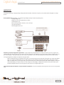
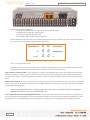
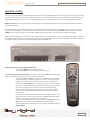
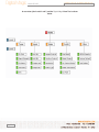
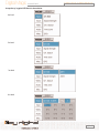
OPERATING INSTRUCTIONS
Digital Magic
Video Processor, STB, and 12 Channel DA
Model KD-DH12
Digital Magic is an all-in-one ATSC Set Top Box, Scaler to convert the video
program to match your display’s native resolution, and 12-channel
Component/Composite Video/Audio Distribution Amplifier:
- Set Top Box (tuner with RF analog NTSC and 8 VSB ATSC Inputs)
- Component (YPbPr) and Composite Video (CV) I/O
- L&R analog stereo and digital PCM Audio I/O
- High-quality scaling to perfectly match the input video to your
display’s native resolutions
- Distribution Amplifier with 12 separate A/V outputs
It is suggested that all users always check our web site for the latest version
of this Users Manual at www.keydigital.com under Literature, User Manuals.
Digital Magic
OPERATING INSTRUCTIONS
Model KD-DH12
DIGITAL MAGIC - Model KD-DH12
UL LISTED
Safety Instructions – Please be sure to follow these instructions for safe operation of your unit
*********************************************************************************
Read these instructions.
Keep these instructions.
Heed all warnings.
Follow all instructions.
Do not use this apparatus near water.
Clean only with dry cloth.
Do not block any ventilation openings. Install in accordance with the manufacturer’s instructions.
Do not install near any heat sources such as radiators, heat registers, stoves, or other apparatus (including amplifiers)
that produce heat.
Do not defeat the safety purpose of the polarized or grounding-type plug. A polarized plug has two blades with one wider
than the other. A grounding type plug has two blades and a third grounding prong. The wide blade or the third prong are
provided for your safety. If the provided plug does not fit into your outlet, consult an electrician for replacement of the
obsolete outlet.
Protect the power cord from being walked on or pinched particularly at plugs, convenience receptacles, and the point
where they exit from the apparatus.
Only use attachments/accessories specified by the manufacturer.
Use only with the cart, stand, tripod, bracket, or table specified by the manufacturer, or sold with the apparatus. When a
cart is used, use caution when moving the cart/apparatus combination to avoid injury from tip-over.
Unplug this apparatus during lightning storms or when unused for long periods of time.
Refer all servicing to qualified service personnel. Servicing is required when the apparatus has been damaged in any
way, such as power-supply cord or plug is damaged, liquid has been spilled or objects have fallen into the apparatus, the
apparatus has been exposed to rain or moisture, does not operate normally, or has been dropped.
*********************************************************************************
Page 2
Digital Magic
Model KD-DH12
OPERATING INSTRUCTIONS
HOW TO CONTACT KEY DIGITAL
Repairs and Warranty Service:
Should your Digital Magic require warranty service, please contact Key Digital first to obtain a Returned Materials
Authorization (RMA) number
Please contact us at either:
Toll-free 1-203-778-0295 extension 3#
email [email protected]
Technical Support:
For technical questions about using our products, please contact us at either:
1-203-778-0295 or Toll-free 1-888-258-2028
email [email protected]
Customer Support:
For customer support questions about using our products, please contact us at either:
1-203-778-0295
email [email protected]
WARRANTY
All Key Digital products are built to high manufacturing standards and should provide years of trouble-free operation.
They are backed by a limited two-year parts and labor warranty.
Page 3
Digital Magic
OPERATING INSTRUCTIONS
Model KD-DH12
Digital Magic
Model # KD-DH12
Key Digital “Digital Magic” (Model KD-DH12) is a state-of-the-art ATSC Set Top Box that scales to your display’s native resolution and distributes
the Video and Audio to up to 12 displays.
Why you need Digital Magic, Model # KD-DH12
Key Digital engineered Digital Magic (Model # KD-DH12) as a simple, convenient, yet high-quality solution for applications where you have RF
Inputs that need to be decoded, scaled, and distributed to an array of displays. Digital Magic offers just what the retail outlets, hotels, casinos,
and even high-end custom home theater installers are looking for -– a unique “one-stop shopping” solution for applications where you need to
decode off-the-air or Cable (RF) ATSC & NTSC, or 480i baseband (YPbPr & CVBS Composite Video) input signals, scale them to your display’s native
resolution, and then distribute them to up to 12 displays.
Since it is a Set Top Box that decodes ATSC and NTSC, you can route just ONE RF off-the-air or Cable feed run throughout your facility, and input it
directly to Digital Magic. Digital Magic then takes over as an ATSC/NTSC decoder, and can even scale the source to match the native resolution of
your display. For example, Digital Magic can down-convert your 1080i input video to 480i, or up-convert your 480i inputs to 480p, 1080i, or 720p.
The high-quality scaler, equipped with Key Digital’ advanced, motion-assisted de-interlacing algorithm called “Clear Matrix”, lets you up-, down-,
and cross-convert the input to your display’s native resolution. Digital Magic supports output formats of 1080 interlaced, 720 progressive, and
480 interlaced and progressive; 60 Hz output refresh rates; and aspect ratios in and out of 16:9 and 4:3.
Digital Magic has 12 discrete Distribution Amplifier (DA) outputs selectable between Component Video (YPbPr) or Composite Video (CV, or “CVBS”).
All of the outputs will display the same resolution and in the same mode (Composite or Component Video). Digital Magic also handles your audio
requirements, with analog (Left & Right stereo pairs) and digital PCM audio supported at the input, and distributed to the discrete outputs. You
can literally run just one RF/Cable feed into Digital Magic, and then drive an entire array of displays (up to 12 without the need for an additional
DA). Since Digital Magic has a front-end tuner, you can have multiple programs even on your internal cable network, and feed several Digital Magic
units tuned to their respective channel. For retailer demo room applications, you can readily add channels without the need for additional wiring.
And there is no need to route multiple YPbPr cable feeds, except from the very output of the built-in Digital Magic DA to your actual display devices.
With its user-friendly On-Screen-Display (OSD), programmable IR remote with “hot” buttons (discrete IR commands are available), and user-selectable output resolutions and aspect ratios, Digital Magic is easy to control and operate. It is rack-mountable (2RU), has no fan noise, and is easy
to install and integrate into your system. The RS-232 port is equipped with discrete command protocol compatible with all control systems (like
Crestron, AMX, CNMSX-PRO), and is even designed to allow customers to upgrade firmware over the Internet.
Page 4
Digital Magic
Model KD-DH12
OPERATING INSTRUCTIONS
Characteristics of Digital Magic, Model # KD-DH12
Supported Input types include:
-
RF ATSC (8 VSB)
RF NTSC
Component Video YPbPr or Composite Video (CV) (480i baseband)
60 Hz refresh
16:9 and 4:3 Aspect Ratios
Supported Output types include:
-
1080i
720p
480i and 480p
60 Hz refresh
16:9 and 4:3 Aspect Ratios
Each of the outputs of the Distribution Amplifier will share the same properties, as configured by the user
Input Connections — One Input Group consisting of:
- Two F-type RF tuner inputs, both capable of ATSC (8 VSB) and analog TV (NTSC)
- Three color-coded RCA connectors for one Component Video (YPbPr) or one Composite Video (CVBS on “Y” connector) input
- Three color-coded RCA connectors for one Analog Audio (standard line-type stereo Left & Right pairs) and one Digital PCM Audio input
Output Connections — 12 separate Output Groups, each consisting of:
- Three color-coded RCA connectors for one Component Video (YPbPr) or one Composite Video (CVBS on “Y” connector) output
- Three color-coded RCA connectors for one Analog Audio (standard line-type stereo Left & Right pairs) and one Digital PCM Audio output
Features:
- Scaler equipped with advanced, motion-assisted de-interlacing algorithm “Clear Matrix”
- User-friendly on-screen-display
- IR remote with ‘hot’ keys
- Channel / status display and controls for complete navigation and operation from the front panel
- RS-232 port for external control of Digital Magic (Crestron compatible), and firmware upgrades
Page 5
Digital Magic
Model KD-DH12
OPERATING INSTRUCTIONS
QUICK SET-UP
Connecting and using your Key Digital Digital Magic (Model # KD-DH12) combination Set Top Box, Scaler, and Distribution Amplifier is a simple
process.
Become familiar with Digital Magic. Your KD-DH12 Digital Magic package includes the following items:
• One Digital Magic unit
• IR Remote Control with 2 AAA batteries included
• Standard power cord
• Rack mounting hardware: brackets, screws, and clips
• This Operating Manual
• Warranty Registration Card
Determine your particular application requirements. A typical application for Digital Magic is in a retail store where you have an off-the-air or
cable NTSC/ATSC feed that you want to decode, scale to the native resolution of the displays you are demonstrating, and then distribute the A/V to
up to twelve displays. With Digital Magic, you have all of these capabilities in one convenient package, and with a minimum of cable routing.
Some typical Application Examples are depicted in the figure below.
When considering the type of configuration you require, you’ll need to know if you have RF inputs (like off-the-air or cable, where Digital
Magic can support two independent inputs), or 480i Component Video (YPbPr) or baseband Composite Video (CVBS) Inputs (Digital
Magic can support either). On the output side, you’ll need to know if you are driving all Component Video (YPbPr) displays, or Composite
Video (CVBS) displays. As well, the audio I/O can be analog stereo Left & Right, or digital PCM. Remember, each of the outputs of the
Distribution Amplifier will share the same properties and resolution, as configured by the user.
Connect the A/V Inputs and Outputs to suit your particular configuration. First, become familiar with the I/O panel, which is at the rear of Digital
Magic.
Page 6
Digital Magic
OPERATING INSTRUCTIONS
Model KD-DH12
Note the back (rear) panel configuration:
• 12 Output Groups labeled “Output 1 – Output 12”, across the entire back panel
• One Input Group, on the far-right of the back panel
• One RS-232 port, upper-left of the back panel
• One standard power plug, upper-right of the back panel
The Input and Output Groups have simple, color-coded female RCA jack connectors for your wiring convenience. A legend on the back of
the unit corresponds to the following configuration across all of the I/O:
Right Analog Audio
Pb
Y or CV*
O O
O O
O O
Left Analog Audio
PCM Digital Audio
Pr
*Note: CV = Composite Video, or CVBS
In addition to the above connectors, the Input Group also includes two female F-type connecters for your RF input, labeled “Ant A” and
“Ant B” and may also appear correspondingly as “Ant 1” and “Ant 2” in some versions of the OSD menu.
Place the unit in a convenient location. This is a good time to rack-mount your Digital Magic unit, with the 2 RU mounting hardware included.
Rubber feet also allow you to place the unit on a counter. Note that the top of the unit has openings in the grate which you should keep unobstructed to permit air-flow to the power supply and the rest of the unit. Also, do not obstruct the IR path (a red lens on the right side of the front
panel).
Make the final connections. Be sure to connect the power cord to the rear of the unit and to a standard wall outlet. You may also connect the RS232 port to your Home Theater Automation System (like Crestron, AMX, or CNMSX-Pro), or in the future use this port with your personal computer
for Digital Magic firmware upgrades.
Please see the Appendices at the end of this manual for instructions on using the RS-232 port for firmware
upgrades and external control of your Digital Magic unit.
Learn to operate the unit with its user-friendly OSD and controls. You can use the Remote Control or use the Pushbuttons on the front panel of
the unit. A front-panel LCD also displays the current channel number (for RF inputs) or the status of the unit during menu manipulation. See the
section below for a more detailed description of the easy navigation / control of your unit and user-friendly On-Screen Display (OSD) menus.
Page 7
Digital Magic
Model KD-DH12
OPERATING INSTRUCTIONS
NAVIGATION / CONTROL
It is most convenient to operate your Digital Magic with the Remote Control provided with your unit. However, you also have the option to go directly to the front panel and use the front-panel Pushbutton switches. It is recommended that you first learn the basic function of the Remote Control
and front-panel Pushbuttons / LCD. Then, a more detailed description of the actual OSD menus and set-up / control of Digital Magic will follow.
Navigation / Control: before you go through the OSD menus, first become familiar with the Remote Control, front-panel Pushbuttons, and frontpanel LCD status display.
First follow the Quick Set-Up instructions provided in this Operating Manual to physically connect Digital Magic into your system. Then, apply
power to the unit and batteries to your Remote Control, and turn the unit “On” with either the front-panel Power switch on the far left, or the red
POWER switch on the Remote Control. The LCD display will indicate the power-up status. The Power switches toggle the unit On/Off.
Next, you will start “Navigating” and “Controlling” your Digital Magic unit, with either the Remote Control or the front-panel Pushbutton switches. As
you Navigate and Control, you will receive feedback through the front-panel LCD display. Much more detail is provided via the OSD that will appear
on one of the displays connected to any of the Digital Magic outputs, described later.
Bring up the OSD Menu on your output display by either:
• Pressing the MENU button on the Remote Control.
• Pressing the Menu Pushbutton on the front panel of the unit.
Learn the basic operation of the OSD menus. Once you bring up the main Menu, push the Navigation
arrows on the Remote Control or four front-panel pushbuttons, as follows:
• Pressing the Down and Up arrows allows you to scroll within the menu through
the different options. For example, if you are in the “Video” menu, you can scroll
through the main Video functions, like “Aspect (Ratio) Control” or “Resolution”.
• Pressing the Left and Right arrows allows you to go to the next logical “level” of
the menu. For example, if you are in the “Video”/”Resolution” menu, you can then
press “Right” to bring you to the next level of the menu, namely the various
Resolution options, like 1080i, 720p, 480p, or 480i. Then, press Down and Up
arrows to scroll through the resolutions until you have reached the desired one,
such as 1080i.
• When you are in a Menu and have reached your desired selection, such as in the
“Video”/”Resolution”/”1080i” example, then press the Select (front-panel) or OK
(Remote Control) button to make and store your selection.
• When you are completed with your set-up, you can press Escape (front-panel) or
EXIT (Remote Control) to remove the OSD and resume normal viewing.
• Normally when the unit is ON and you are not navigating, the LCD will display the
Channel Number.
Page 8
Digital Magic
Model KD-DH12
OPERATING INSTRUCTIONS
Learn the “Hot” buttons on your Remote Control. In addition to Remote Control unit pushbuttons described above, and the VOL. +/- (Volume
Up/Down), MUTE, and CH +/- (Channel Up/Down) pushbuttons, consider these “Hot” buttons on the Digital Magic Remote Control that will take you
directly to specific menu adjustments:
• GUIDE [EPG, Electronic Program Guide]
• TEST PAT. [Test Patterns]
• EXT. PCM [external digital PCM audio, SPDIF]
• CV Out [Composite Video Out]
• RES. [Output Resolution select]
• ASPECT [Output Aspect Ratio selection, 16:9 or 4:3, letterbox]
• INPUT [Select Antenna A/B (1/2), Component, or Composite Video In]
You may also use the lower half of the Remote Control unit to select the channel number and add/delete channels to your “Favorite”
channel list.
Learn the “Hot” buttons on the front panel.
• Note the Resolution Pushbutton on the right side of the front panel. By pressing this button and observing the LCD frontpanel display, you can cycle through the various output resolution options available, namely 1080i, 720p, 480p, or 480i. This
is a particularly useful feature in the event you use the front-panel navigation to select an output display option that is not
compatible with your current display device, and you “lose” the OSD feature. Simply press the front-panel Resolution button
and you will be prompted as to wheter you want to change the display resolution [Yes or No]. If you select “Yes”, continue to
press the front-panel Resolution pushbutton as you cycle through the different resolution options, stopping on a desired one
that is compatible with your display device, as noted on the front-panel LCD.
• A Reserved Pushbutton is available for future expansion.
Page 9
Digital Magic
OPERATING INSTRUCTIONS
Model KD-DH12
OSD MENUS
OSD Menus: Now that you know how to navigate through the menus using the Remote Control or front-panel Pushbutton switches, learn the OSD
Menus. The OSD Menus allow the user to specifically configure Digital Magic to match your specific requirements. For example, if you are using
the Antenna A (also called Antenna 1) input, and want to display Composite Video (CV) to your 480i CV input displays, you can use the Navigation
system described previously and follow the OSD Menus to program your Digital Magic accordingly.
The user-friendly OSD Menu Structure for your Digital Magic unit is outlined below. The structure also gives you a clear idea of what aspects of
Digital Magic you can configure and control.
You can see that the first and second levels in the OSD Menu Structure includes user controls as listed in the following table. You would use
the Down and Up arrows on the Remote Control or front-panel Pushbuttons to scroll through the first-level controls, then use the Left and Right
arrows to move to the next level.
OSD MENU STRUCTURE LEVELS 1 AND 2
LEVEL 1 LEVEL 2
Tuner
•CH Edit
•Show CH. List and Edit CH.
•CH Search
•Automatically searches for active channels
•Signal Strength
•Time Zone
Input
•EPG
•Ant 1 (Ant A on back of unit)
•Ant 2 (Ant B on back of unit)
•Component
Video
Description
•Composite
•Aspect Control
•Position Control
•Resolution
•Show Signal Strength
•Select your Time Zone
•Display the Electronic Program Guide
Select the type of Input Signal you want to process
and display
•Select the Aspect Ratio to match your display and
desired mode, including 16:9, 4:3, Full-screen,
Letterbox
•Fine-tune the Horizontal Position (+/- 40) and
Vertical Position (+/- 20) of the output video, to properly fill your display screen
•Select the Output Resolution to match the native
resolution of your display, either 1080i, 720p, 480i, or
480p, and when prompted respond whether “Did you
•CV Out
Audio
•Select either Component Video (YPbPr) or
Composite Video (CV) out to drive up to 12 corresponding displays
•Dual Mode
•Main/Sub, Main, Sub, Mono
•Vol Control Setup
•On/Off, Volume Control by Set Top Box
•Digital Out
•Audio Connection
Misc.
change display mode: Yes/No”
•Ext. PCM
•Menu Opacity
•Factory Default
•Test Pattern
•Select AC3 or PCM out
•Select Digital or Analog (sets reference channel
input for Volume Control)
•SPDIF/Ext. PCM
•Select Opacity 1 (minimum) to 4 (maximum)
•Resets all settings to Factory Default levels
•Select video test patterns to your output: Color
Bars, White Black, or Gray Bar
Level 1 is considered the Main OSD Menu, and each level thereafter provides further detail of the selected feature.
Page 10
Digital Magic
Model KD-DH12
OPERATING INSTRUCTIONS
An overview of the Levels 1 and 2, and the Digital Magic Menu Tree is shown
below:
Page 11
Digital Magic
Model KD-DH12
OPERATING INSTRUCTIONS
A snapshot of a typical OSD Menu is shown below:
1st level
2st level
3st level
4st level
Page 12
Digital Magic
OPERATING INSTRUCTIONS
Model KD-DH12
Technical Specifications
Digital Magic
Model # KD-DH12
Product Summary
- Combination Set Top Box, Scaler, and Distribution Amplifier
Inputs
• Two RF tuner inputs, both capable of ATSC (8 VSB) and analog TV (NTSC)
- One 480i baseband Component Video (YPbPr) or Composite Video (CVBS) input
• One analog (standard line-type Left & Right pairs) and one digital PCM Audio input
Scaling and Processing
• Scaler equipped with advanced, motion-adaptive de-interlacing algorithm “Clear Matrix”
• Scaling SDTV to popular native resolutions and output formats of:
• 1080 interlaced
• 720 progressive
• 480 interlaced and progressive
• Aspect Ratios in and out: 16:9 and 4:3
• 60 Hz output refresh rate
- Each of the outputs of the Distribution Amplifier will share the same properties, as configured by the user
Twelve Output Groups, each consisting of discrete:
• Component Video (YPbPr), with Composite Sync on Y, or Composite Video (CVBS) out on “Y” connector only if CV output mode selected
• One analog stereo pair (standard line-type Left & Right) and one digital PCM Audio outputs
Control
• Infrared Remote Control with “hot” buttons; discrete IR commands available
• User-friendly on-screen-display
• RS-232 port equipped with discrete command protocol compatible with control systems (e.g., Crestron, AMX, CNMSX-PRO)
• Firmware upgradeable
Connectors
• Input Connections — One Input Group consisting of:
- Two F-type RF tuner inputs, both capable of ATSC (8 VSB) and analog TV (NTSC)
- Three color-coded RCA connectors for one Component Video (YPbPr) or one Composite Video (CVBS on “Y” connector) input
- Three color-coded RCA connectors for one Analog Audio (standard line-type stereo Left & Right pairs) and one Digital PCM Audio input
• Output Connections — 12 separate Output Groups, each consisting of:
- Three color-coded RCA connectors for one Component Video (YPbPr) or one Composite Video (CVBS on “Y” connector) output
- Three color-coded RCA connectors for one Analog Audio (standard line-type stereo Left & Right pairs) and one Digital PCM Audio output
• Other Connections:
• RS-232: D-sub 9-pin female connector
• Standard power plug
Mechanical
• Easy to install and integrate – Retailer’s / Custom Installer’s dream
• Rack mountable: 2RU (brackets included)
• No fan noise
• Size: 17” x 10” x 3.5”
• Weight: 6.3 lbs.
• Enclosure type: Metal
• Input Power: 100 to 240V AC, 50-60 Hz, 0.9 A
Page 13
Digital Magic
OPERATING INSTRUCTIONS
Model KD-DH12
APPENDIX A
Upgrading Digital Magic (Model # KD-DH12) Firmware
From time to time, Key Digital may offer firmware upgrades for Digital Magic. These upgrades will enhance the operation of your Digital Magic
unit, and are easily installed by connecting the RS-232 port (D-sub, 9-pin female connector) on the upper-left rear panel of your Digital Magic unit
to a desktop or notebook PC using a standard RS-232-cable. The files you will need to perform any upgrades are available via e-mail by contacting
us at [email protected], or you can download them from our Key Digital web site at http://www.keydigital.com/downloads/DH12upgrade.zip
Once you have downloaded the necessary executables and firmware upgrade files from our Key Digital web site onto your computer, please follow
these simple steps for Firmware Upgrade using the Flash Manager:
With your Digital Magic unit in the Power-OFF condition, connect the RS-232 port of your Digital Magic unit to the COM port of your computer using
a straight RS-232 cable (not a null modem cable).
Execute “flashman.exe” on your PC and select a COM port (COM1 or COM2). If you select an occupied COM port, an error message will alert you to
close the program and execute it again.
Press the [LOAD] button and select the binary file (“flash_xxxx.bin”). If the file is loaded correctly, the program will display a check sum value
that must have the same value as in file name.
Press the [PROGRAM] button ( “Looking for a STB connected... “) and press the POWER button on the Digital Magic front panel (Power-ON). If the
download process is proceeding properly, a message will advise you of the download progress. The download process may take up to 8 minutes
— please wait for the entire download to complete, and do not disrupt this process.
NOTE: If the “flashman.exe” does not execute properly, then repeat the steps 2 – 4 above. The “flashman.exe” generates a
“flashman.cfg” file in the first execution. If the download message does not appear, try powering OFF and ON your Digital Magic unit.
If the download has been successful, the “All Programming Done” message will appear. At this time, Power OFF your Digital Magic unit. Then, close
the Flash Manager program and again turn ON the Power to your Digital Magic unit, execute the “FACTORY DEFAULT” in the menu function, and
check the unity.
It is now a good idea to check the basic operation of your Digital Magic unit to be sure that it is working properly and the upgrade was indeed successful. Should you encounter any problems during or after your firmware upgrade procedure, call us toll-free at 1-866-780-5069 or contact us by
e-mail at [email protected].
Page 14
Digital Magic
OPERATING INSTRUCTIONS
Model KD-DH12
APPENDIX B
Controlling Digital Magic (Model # KD-DH12)
from your Home Theater Automation System
For integration with your existing equipment, your Digital Magic unit can be conveniently controlled from your existing Home Theater Automation
System (like Crestron, AMX, or CNMSX-Pro) by using the discrete command protocol. You will need to locate the RS-232 port (D-sub, 9-pin female
connector) on the upper-left rear panel of your Digital Magic unit, and connect it to your Home Theater Automation System using a standard RS232-cable. You will be able to use your existing Home Theater Automation System to control the following Digital Magic functions:
Input select
Tuner channels Up and Down
Channel ##-# select
Aspect Ratio
Output resolution
Output format
Following is an example of how to use a communication program (such as Hyper Terminal) to generate the commands to control the above functions of your Digital Magic unit using the discrete command protocol:
With your Digital Magic unit in the Power-OFF condition, use a straight RS-232 cable (not a null modem cable) to connect the RS-232 port of your
Digital Magic unit to the RS-232 port on your PC. Use the following settings:
Set the Hyper Terminal to COM1*
Baud Rate: 57600
Data: 8-bit
Parity: None
Stop: 1 bit
*Note: make sure you are not running any other active program using COM1, such as the “Hot Sync” Palm program
Turn ON the Power to your Digital Magic unit. In your Hyper Terminal window, press [ENTER]. You will be prompted with:
Key Digital Digital Magic RS-232 control
DH12>
The help menu and the rest of the commands should be very simple:
Input select
Tuner channel Up and Downs
Channel ##-# select
Aspect Ratio
Output resolution
Output format
Note that in RS-232 command mode, the Digital Magic Remote Control and front-panel Pushbuttons are non-functional.
If at any time you want to escape from the RS-232 command mode, type “exit” on your terminal and press [ENTER].
Page 15
Digital Magic
Model KD-DH12
OPERATING INSTRUCTIONS
You now have the background to use the discrete command protocol to control the functions on your Digital Magic unit. For example, consider control of Digital Magic’s Input Selection:
Press [ENTER] (changes to RS-232 command mode, “testtool” program prompt)
Type “command of input selection” on your terminal and press [ENTER]
se the MACRO function of your terminal program. The meaning of a MACRO is a “batch” file of several commands that let you conveniently use one
or two terminal keystrokes to execute several commands
April 2004