1
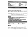
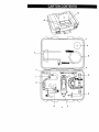
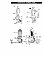
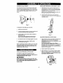
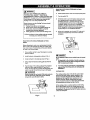
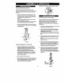
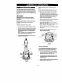
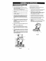
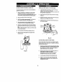
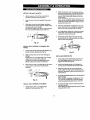
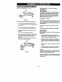
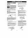
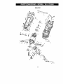
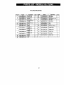
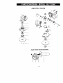
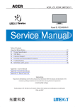
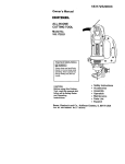
Owner's
Manual
CRRFTSHRN®
ALL-IN-ONE
CUTTING TOOL
Model No.
183.172540
Important
Safety
Notice
[_, WARNING I
Always have one hand firmly
placed on the tool body while
operating, Never operate the
tool by holding only the tool
handle.
•
Safety Instructions
CAUTION:
•
Accessories
Before using this Cutting
Tool, read this manual
and follow all its Safety
•
Assembly
•
•
Operation
Maintenance
Rules and Operating
Instructions,
•
Parts
•
Espanol
Sears, Roebuck
and Co., Hoffman Estates,
Part, No, 183172540001
Rev. 0 07/21/03
List
IL 60179 USA
Safety and Assembly
Instructions
ASSEMBLY
CRRFTSMRN®
FLEX SHAFT for
ALL-IN-ONE
CUTTING TOOL
Model No.
183.287660
INSTRUCTIONS
t.
Turn cutting tool motor switch OFF and remove
plug from the power source.
2.
Lock main shaft (3) by rotating the collet nut (1)
while pressing on the spindle lock button (4)
until the spindle lock prevents shaft from
rotating (see Fig 1).
3.
Use cutting tool fiat wrench (5) to loosenthe
collet nut by turning it counter clockwise.
Remove collet (2) from inside main shaft of
cutting tool.
2
IAWA.N,.G
J
3
ALWAYS WEAR EYE PROTECTION. Any power
tool can throw foreign
which could cause
permanent eye damage.
ALWAYS
wear
safety
objects into
your
eyes
goggles (not glasses) that
comply with ANSI safety
standard Z87.1. Everyday glasses have only
impact resistant lenses. They ARE NOT safety
glasses, Safety goggles are available at most
hardware stores,
Fig. 1
4.
Insert collet with square hole (6) intomain shaft
(3) and re-install the collet nut (1) onto the main
shaft (see Fig. 2).
NOTE: Coll_t with square hole is packed with
the flex shaft package.
5.
Use cutting tool fiat wrench (5) to tightenthe
collet nut firmty onto the main shaft while
spindle lock is engaged into the main shaft,
Turn nut clockwise to tighten.
Glasses or goggles not in compliance
with ANSI
Z87.1 could cause serious injury when they
break.
USE FACE OR DUST MASK along with safety
goggles if cutting or routing operation is dusty.
Make sure work area is well ventilated.
NEVER PLACE HANDS IN THE PATH OF THE
CUTTER or under the workpiece.
USE HEARING PROTECTION, particularly
during extended periods of operation,
ALWAYS RE-TIGHTEN COLLET before starting
the tool after a cutting bit or accessory has
been changed. Loose bits and accessories can
cause unexpected shifting of the tool, resulting
in loss of control and injury from the bit or
cutting tool being thrown.
NEVER TOUCH THE CUTTING BIT
IMMEDIATELY AFTER USE. The bit will be too
hot to be handled with bare hands and will burn
your fingers.
Sears, Roebuck
Part. No. 183287660003
Rev. 3
and Co., Hoffman
07129102
Fig. 2
Estates,
IL 60179 USA
SECTION
Warranty ........................................
ProductSpecifications......................
PowerTool Safety ............................
CuttingToct & AccessorySafety .........
ElectricalRequirement& Safety ..........
CuttingTootSymbols........................
PAGE
2
2
3
4
5
6
SECTION
ACCSS_
PAGE
....................................
Carton Contents ..............................
Know Your Cutting Toct ....................
Assembly & Operation ......................
Maintenance ...................................
Repair Parts ...................................
7
7911
24
25
8
10
- 23
- 36
FULL ONE YEAR WARRANTY
If this Cutting Tool fails due to a defect in material or workmanship within one year of date of
purchase, Sears will at its option repair or replace it free of charge.
Return this Cutting Tool to a Sears Service Center for repair, or to place of purchase for
replacement.
This warranty gives you specific legal rights, and you may also have other dghts which may vary
from state to state.
Sears, Roebuck and Co., Dept. 817 WA, Hoffman Estates, IL 60179
[A WARNINGJ
Some dust created by power sanding, sawing, grinding, drilling and other construction activities contains
chemicals known (to the State of California) to cause cancer, birth defects or other reproductive harm. Some
examples of these chemicals are:
•
Lead from lead-based paints
•
Crystalline silica from bricks, cement and other masonry products
•
Arsenic and chromium from chemically treated lumber
Your risk from these exposures varies, depending on how often you do this type of work. To reduce your
exposure to these chemicals, work in a well ventilated area and work with approved safety equipment such as
those dust masks that are specially designed to filter out microscopic particles,
Motor Rating ......................
120 V, 60 Hz, AC
Motor Horsepower ......
3/4 HP (Maximum Developed)
Amperes
5.0 A
Weight
3 lb. 12 oz, (1.7 kg)
20,000 & 30,000 RPM
Maximum Disc SiZe ....
...........................
Two Speeds (no load) .........
J_
WARNING
.....................
4" Diameter
I
To avoid electrical hazards, fire hazards or damage to the tool, use proper circuit protection.
This power tool is wired at the factory for 110-120 V operation. It must be connected
to a 110-120 V 115 A time
delayed fuse or circuit breaker. To avoid shock or fire, replace power cord Immediately if it is worn, cut or
damaged in any way.
Before using your cutting tool, it Is critical that you read and understand these safety rules, Failure to follow
these rules could result in serious Injury to you or damage to the cutting tool.
2
Safety and Assembly
ASSEMBLY
6.
7.
INSTRUCTIONS
Instructions
- cont'd
Align the flex shaft connector cap (6) wfth the
cutting tool motor housing (8) (see Fig. 3).
NOTES:
a) Carefully align the square end of the flex
shaft center core so it will engage into the
square hole in the collet.
b) Make sure the keyway (7) in the inside of
the connector cap aligns with the matching key
(8) on the motor housing.
c) Oocasionally the flex shaft inner core may
slide out of the outer casing durthg handling. If
this should happen, simply reinsert the inner
core into the outer casing from the connector
cap end of the flex shaft. Rotate the ironer core
to ensure the square end is properly engaged in
the collet assembly.
When shaft center core and connector cap are
properly aligned, slide the connector cap fully
onto the motor housing. Lock connector cap
into place by pressing on the quick connect
lever (g).
t2
11
Fig. 4
To Change Cotlet Size
The flex shaft comes with two differentcollets+ One
is for 1/8" shank bits and the other is for 3/32"
shank bits.
1.
Loosen collet nut on end of shaft as outlined in
step #8 above.
2.
Remove collet nut (12) and remove collet (13)
from end of shaft (14) (see Fig. 5).
3.
Insert correct collet in the end of the shaft.
4.
Reinstall collet nut on shaft.
12
9
13
13
,o
Fig. 3
8.
9.
To insert an accessory into the flex shaft collet,
rotate collet nut (12) until hole in shaft aligns
with hole in flex shaft collar (11) (see Fig. 4).
insert Allen key (10) into aligned holes and use
the small fiat wrench supplied (13) to turn toilet
nut counter clockwise.
When collet is loose, insert accessory and turn
col)atclockwise to tighten, making sure the
accessory is centered in the collet, Use the
small fiat wrench to tighten clockwise.
14
Fig. 5
Ih, CAU ON
I
Do not store or operate flex shaft with a bend
radius of less than 6" (150ram) (see Fig. 6).
10. Remove Allen key and rotate the ¢otlet by hand
to ensure accessory does not wobble.
Fig. 6
[_
WARNING--]
Before using your cutting tool, it is critical
that you read and understand these safety
rules. Failure to follow these rules could
result in serious injury to you or damage to
the cutting tool
Good safety practices are a combination of common
sense, staying alert and understanding how to use your
power tool. To avoid mistakes that could cause serious
thjuty, do not pJug in your cuing tooJuntil you have read
and understoo_ the follOWing safety rules:
READ and become familiar with this entire Owner's
Manual. LEARN the tool's applications, limitations and
possible hazards.
t-,_ WARNING_
LOOkfor this symbo_that identifies important safety
precautions. It means CAUTIONI BECOME ALERTt,
YOUR SAFETY IS INVOLVEDI
Dress properly. Do not wear loose clothing or jewelry
Contain long hair. Keep your hair, clothing and
gloves away from moving parts. Loose clothing.
jewelry or long hair can be caught In moving parts.
Avoid accidental starting. Re sure switch is OFF
before plugging in. Carting too_swith your finger on
the switch or plugging in tools that have the switch ON
invites accidents.
Remove
the tool
adjusting
keys or wrenches
before turning
ON. A wrench or key that is left attached to a
rotating part of the tool may result in personal injury
Do not overreach.
Keep proper footing and balance
at all times. Proper footing and balance enables better
control of the toct in unexpected situations.
Use safety equipment. Always wear eye protection.
Dust mask, non-skid safety shoes, hard hat or
hearing protection must be used for appropriate
conditions.
GENERAL SAFETY RULES
TOOL USE AND CARE
KEEP GUARDS IN PLACE and in working order.
ALWAYS WEAR EYE PROTECTION. Any power tool
can throw foreign objects into your eyes
damage. ALWAYS wear safety goggles
which
cOUldcause
permanent
eye
(not glasses)
that comply
with ANSI
safety standard Z87.1. Everyday
glasses have only impact resistant lenses. *l_heyARE
NOT safety glasses. Safety goggles are available at
Sears.
IA,WARN'NGI
Glasses or goggles not in compliance with ANSI
Z87,1 could cause serious injury when they break.
WORK AREA
Keep your work area clean and well lit. Cluttered
benches and dark areas invite accidents.
Do not operate power tools in explosive
atmospheres, such as in the presence of flammable
liquids, gasses or dust. Power tools create sparks
which may lgntte the dust or fumes.
Keep bystanders, children and visitors away while
operating the tool. Distractions can cause you to lose
control
PERSONAL SAFETY
Stay alert, watch what you are doing and use
common sense when operating a power tool. Do not
use the toot while tired or under the influence of
drugs, alcohol or medication. A moment of inattention
while operating power tools mey result in serious
person_ injury.
SAVE THESE
Use clamps or other practical way to secure and
support the workpiece to a stable platform. Holding
the work by hand or against your body is unstable and
may lead to Jossof control.
Do not force the tool Uae the correct tool for your
application. The correct tooIwill do the job better and
safer at the rate for which it is designed.
Do not use the tool it the switch does not turn it ON
or OFF. Any tool that cannot be controlledwith the
switch is dangerous and must be repaired.
Disconnect the plug from the power source before
making any adjustments, changing accessories or
storing the tool. Such preventive safety measures
reduce the risk of starting the tool accidentally.
Store idfa toots out of reach of children
untrained
persons.
Tools are dangerous
untrained users.
and other
in the hands of
Maintain tools with care, Keep cutting tools sharp
and clean. Preper/y maintained cutting tools with sharp
cuttingedges are less likely to bind and are easier to
control.
Check for misalignment
or binding of moving parts,
breakage of parts and any other condition that may
affect the tool's operation. If damaged, have the tool
serviced before using. Many accidents are caused by
poorly maintained too!s.
Use only accessories that are recommended by the
manufacturer for your model Accessories that maybe
suitable for one tool may become hazardous when used
on another tool
INSTRUCTIONS
FOR REFERENCE
SERVICE
ANGLE GRINDER
SAFETY
L='wAr.J.G
I
Tool service must be performed only by qualified
personnel Service or maintenance performed by
unqualified personnel could result in risk of injury.
Always wear safety goggles with side shields or a
face mask when using the angle grinder attachment.
High speed grinding and sanding will throw hot
sparks and dust particles that could cause serious
injury to your eyes.
When servicing a tool, use only identical
replacement parts. Follow instructions in the
Maintenance section of this manual. Use of
unauthorized parts or failure to follow Maintenance
instructions may create a dsk of electric shock or injury.
SPECIFIC
ATTACHMENT
Always wear hearing protection
grinder attachment.
SAFETY RULES
when using the angle
Always use appropriate dust mask when using the
angle grinder attachment.
Hold tool by insulated gripping surfaces when
performing an operation where the cutting tool may
contact hidden wiring or its own cord. Contact with a
"live" wire will make exposed metal parts of the tool "live"
and shock the operator.
Use ONLY grinding wheels and sanding discs rated
for speeds greater than 18,000 RPM, as the angle
grinder attachment runs st speeds from 12,000 18,000 RPM.
Always make sure the work surface is free from nails
and other foreign objects, Cutting into a nail can cause
the bit and the tool to jump and damage t_e bit.
Inspect the grinding wheel before each use to make
sure it is tightly fastened and free from cracks or any
other damages.
Never hold the workpiece in one hand and the tool in
the other hand when in use. Never place the hands
near or below the cutting surface. Clamping the
mateda[ and guiding the tool with both hands is much
safer,
Rotate the guard to a position where it will protect the
operator from sparks and dust. The guard should be
positioned immediately in front of the side handle to
protect the operator's hand.
Never lay workpiece on hard surfaces like concrete,
stone, etc. Protruding cutting bit may cause tool to jump.
Do not over tighten the nut holding the grinding
wheel in place. Excessive tightening may cause the
grinding wheel to crack and possibly shatter dudng
operation.
Always wear safety goggles, hearing protection and
dust mask. Use only in well ventilated area. Using
personal safety devices and working in a safe
environment reduces risk of injury.
Do not clamp the angle grinder attachment in a vice
or usa as a fixed grinder.
Hold the angle grinder attachment securely with two
hands at ell times while it is running.
After changing the bits or making adjustments, make
sure the collet nut end any other adjustment devices
are securely tightened. Loose adjustment devices will
be violently thrown.
Never turn the motor switch ON with the grinding
wheel or sanding disc touching the work surface.
FLEXIBLE
Never use dull or damaged bits. Sharp bits must be
handled with care, Damaged bits can snap during use.
Dull bits require more force to push the tool, possibly
causing the bit to break.
SHAFT SAFETY
When using the flexible shaft accessory, always
hang the motor unit on a hook using the hanging loop
at the top of the motor housing.
Never touch the bit during or Immediately after use.
After use the bit is too hot to be touched by hare hands.
Always use safety glasses,
dust mask.
hearing protection and a
Never hold the workplace with your hand while using
a cutting biL Clamp the wofkpiece in a vice or to a
workbench to permit using two hands on the flex shaft.
Never place hands in the path of the cutter or under
the wod(piece.
Do not store or operate the flex shaft with a bend
radius of less than g" (150 ram).
SAVE THESEINSTRUCTIONS
4
FOR REFERENCE
IZolUl;pie;il_ F;ll I IP'_,IIIfe__
This cutting tool is double insulated to protect you from
el_l
shock,
WARNIN
N
Double Insulated tools are equipped with a polarized
plug (one blade is wider than the other). This plug
will fit Into a polarized outlet only one way. If the plug
does not fit fully into the outlet, reverse the plug, If it
still does not fit, contact a qualified electrician to
install a polarized outleL Do not alter the plug In any
way. Double insulation eliminates the need for the three
wire grounded power cord and grounded power supply
system.
Avoid body contact with grounded surfaces such as
pipes, radiators, ranges and refrigerators. There is an
increased risk of electric shock if your body is grounded.
Do not expose power tools to rain or wet conditions,
Water entering a power tool will increase the risk of
electric shock.
Do not abuse the cord. Never use the cord to carry
the tool or pull the plug from the outlet. Keep cord
away from heat, oil, sharp edges and moving parts.
Replace damaged cords immediately. Damaged cords
increase the dsk of electric shock.
When operating a power tool outdoors, use an
outdoor extension cord marked '_N-A" or "W". These
cords are rated for outdoor use arm reduce the risk of
• e]ecfric shock,
I_
WARNING I
Always make sure the receptacle is polarized. If you
are not sure, have a qualified electrician check the
receptacle.
Make sure your extension
cord is in good condition.
When using an extension cord, be sure to use one heavy
enough to carry the current the tool will draw. An
undersized cord will cause a drop in line voltage resulting
in loss of power and overheating, The table below shows
the correct size to use according to cord length and
nameplate ampere rating. If in doubt, use the next
heavier gauge. The smaller the gauge number the
heavier the cord.
Be sure your extension cord is propedy wired and in
good condition. Always replace e damaged extension
cord or have it repaired by a qualified electrician before
using it. Protect your extension cord from sharp objects,
excessive heat and damp or wet areas.
Use a separate electrical circuit for your power tools.
This circuit must not be loss than 14 gauge wir_nd
should be protected with either a 15 Ampere time delay
fuse or circuit breaker. Before connecting the power tool
to the power source, make sure the switch is in the OFF
position and the power source is the same as indicated
on the nameplate. Running at lower voltage will damage
the motor.
IA
WARNING
I
Repair or replace damaged or worn extension cords
immediately.
Select the appropriate extension cord gauge and length
using the chart below.
MINIMUM
GAUGE (AWG) EXTENSION
(120 Volt use only)
Ampere Rating
More Than
More
Not
Than
O
6
t0
t2
6
10
12
16
CORDS
Total length in feet
25'
18
18
I 16
I,_14
50' I 100'
150'
16 I 16
14
16 I 14
12
16
14
12
12
NotApplicable
[,_. WARNING J
Keep the extension cord clear of the working area,
Position the cord so it will not get caught on the
workplece, tools or any other obstructions while you
ere worklng with the power tool.
IA
WARNING I
Some of the following symbols may be
your tool. Please study them and learn
meaning. Proper interpretation of these
will allow you to operate the tool better
used on
their
symbols
and safer.
®
This symbol designates that this
tool is listed with U.S.
requirements by Underwriters
Laboratories.
LISTED
V
A
Hz
volts
three-phase
alternating
amperes
three-phase
neutral
alternating current with
W
watt
kW
#F
I
kg
N/cm z
Pa
h
hertz
current
direct current
no
kilowatts
no load speed
alternating
or direct current
micro farads
[]
class II construction
liters
z_
splash proof construction
kilograms
iA
watertight
newtons per square centimeter
@
protective earthing at earthing terminal,
Class I tools
pascals
hours
min
minutes
S
seconds
altemating current
,..Imin
construction
revolutions
o
Diameter
0
Off position
or reciprocations
Arrow
Warning symbol
per minute
AVAILABLE
ACCESSORIES
CUTTING
IA
WARNING J
KEY
Use only accessories recommended for this cutting
tool. Follow instructions that accompany
accessories. Use of improper accessortes may cause
injury to the operator or damage to the Cutting Tool.
_/_" Cutting Bits
_la"& 3132"Hobby Rotary Tool Accessories
_, Cutters
>
Polishers
Sanders
> Grinders
Most '/4"Shank Router Bits
3 '/=" Grinding Disks
4" Sanding Disks
)f:_ ;_l(I]_l
UNPACKING
[e[o]ll
AND CHECKING
i :1_11[,;
B
1
1
1
C
D
Circle Cutting Guide
Beveling Plunge Router Attachment
1
1
E
Angle Grinder Attachment
Hendle
1
F
G
H
t
Cuffing Tool
Freehand Cutting Guide
Removable Handle with Sole Plate
Angle Gdnder Attachment
j
Angle Grinder Attachment Side •
Handle Collar
K
L
Rip Fence
Carr_ng Case
Owner's Manual
Front Lid Storage Compartment
If any part is missing or damaged, de not plug the
Cutting Tool into the power aource until the missing
or damaged part is replaced and assembly is
complete.
Carafully unpack the Cutting Tool and all its components.
Compare against the =Cutting Tool Components" chart.
NOTE: See Page 8 & 9 for illustration of components.
M
LATERAL STYLE DRYWALL
CUTTING
Side
t
I
t
1
5
2
1
1
1
1
1
L-key
CUTTING BIT
This cutting bit has a coarse spiral for removing
particles when beingusedfor generalcutting(see right).
Use this general purpose cutter for cutting materials such
as wood, plastic and fiberglass,
Drywall Bit
7
t
_/8" Wall Tile Bit
1/8" Drywall Bit
lie" All Purpose Bit
¼" All Purpose Bit
Use this cutter for cutting drywall
GENERAL PURPOSE
""
1
Cutting Tool Accessories
_/a" Collet
¼" Collet (in cutting tool)
This cutting bit has a fine spiral for removing high
volumes of fine particles when cutting (see right).
1
t
1
Drive Shaft for Angle Grinder
Attachment
Flexible Shaft Accessories
l/e" Collet
3/==.Collet (in flexible shaft)
Square coilet
Coflet wrench
•
BIT
I QI;Y
120 grit (fine) polishing pad
Sanding disc backing pad
Flexible Shaft
IA WARNINGJ
To avoid fire or toxic reaction, never use gasoline,
naphtha, acetone, lacquer thinner or similar highly
volatile solvents to clean the cutting tool.
COMPONENTS
DESCRIPTION
Inside Carrying Case
1
1
1
1
CARTON CONTENTS
J_. WARNING I
TOOL
Angle Grinder Attachment Kit
Metal cutting disc
Masonry cutting disc
36 grit (coarse} sanding disc
50 grit (medium) sanding disc
A
Visit your Sears Hardware Department or see the
Sears Power and Hand Tool Catalog for an assortment
of accessories recommended for use with this cutting tool:
J
General
Purpose Sit
1
1
1
M
K_
D
H
G
8
F;
Loop
precision
Handle
Motor
Housir
H_ng
C:) <
Quick
Lod_ng
Le_r
Adjusting
KnOb
I_ver
,So4e
Prate
Motor
Housir
Motor
Housing
Depth
StopRod
DepUl
SCale
Height
Mounting
Knobs
Quick
Lever
PSunge
Action Turret
Rip
Knob
Sole Adjusting
Pla_eLoc_
Knob
Mounting
OLSC
Base
Rip Fence
Mount
Grinding
Handle
Mounting
Colla¢
Lockln
Button
Cc41et
Nut
Qulc_
Connect
Lever
Connector
Cap
lO
INSTALLING
CU'FrlNG
BITS - Cont'd
I_ WARNINGI
Remove the plug from the power
assembly, changing accessories
making adjustments. This safety
prevent accidental starting of the
result in serious injury.
ON / OFF & SPEED CONTROL
source before
or cutters and
action will help
tool which could
4.
insert new cutting bit (4) into the coliet.
IA w a=aGI
Insert the bit all the way into the coget and then
pull it back between _/16" and 1/=,,. This creates an
air space between the motor shaft and the bit to
help prevent overheating the bit.
SWITCHES
This Cutting Tool is equipped with a sliding ON / OFF
switch (I) located on the side of the tool and a two speed
control switch (2) located on top of the tool (see Fig. 1).
Before tightening the collet on the bit, make sure
the flutes (spiral portion) of the bit are completely
visible outside the coltat. Clamping the collet on
the bit flutes will result in broken bits and
possible injury.
5.
When bit is propedy placed in the collet, depress the
shaft locking button and turn the coffer nut clockwise
by hand as far as possible.
6.
Securely tighten collet nut using the wreed]::
Fig. 1
1.
To turn the tool ON, slide the switch (1) upward.
2.
To turn the tool OFF, slide the switch downward.
3. To set speed to highspeed, slidethe speed control
switch(2) awayfrom the ON / OFF switch.
4.
3
To set the speed control switch to low speed, slide
the speed control switch (2) towand from the ON /
OFF switch.
INSTALLING
CuI-rtNG
2
Fig. 2
WORK LIGHTS
BITS
IA w .INGI
To insert a cutting bit, use the collet wrench.
The motor unit has two built-in work lights (5) (see Fig. 2)
These work lights automatically light up when the motor
switch is turned ON. Patterns or drawings in the
immediate vicinity of the bit will be illuminated for better
visibility and improved cutting accuracy.
1.
SELECT APPROPRIATE
Cutting bit and router bit cutting surfaces
extremely sharp. Handle with caution.
are
Deprees the shaft locking button (1) and retate the
collet lock nut (2) clock'wise with the other hand until
the Iockiog button drops into place, preventing the
shaft from turning (see Fig. 2).
Selecting the appropriate motor speed will ensure
smoother, more efficient cutting action. Choose LOW
speed for grinding, cuffing ptas6cs, polishing and when
using wire or brisite brushes, Choose HIGH speed when
cutting wood, using the angle grinder attachment, using
cut-off wheels and to reduce "chatter" that may develop
when cutting some matedals at LOW speed.
2. While continuingto holdthe shaft lockingbuttonIN,
use the collet'wrench (3) to rum the colletnutcounter
clockwise,Loosenthe colletnuttwo or three turns,
3.
MOTOR SPEED
Remove bit if one is already installed in the tool
11
CHANGING
COLLET
INSERT
INSTALLING
The cuffing bits for this toot are locked into place with a
collet nut (t) and coflet (see Fig. 3). The l/a" collet (2) is
used for holding hobby tool accessory bits. The ¼" collet
(3) is supplied for holding SMALL router bits with a ¼"
shank.
FREEHAND
CU'I-rlNG GUIDE - cont'd
1.
Slide fi'eehand cutting guide mounting bracket (1)
onto the bottom of motor housing (2) until the slot in
the bracket (3) lines up with the shaft locking button
(4) in the motor housing (see Fig. 4).
NOTE: The mounting bracket must be pushed onto
the motor housing as far as it will go.
2.
Lock the cutting guide to the motor housing by
snapping the quick locking lever (5) firmly against the
mounting bracket.
3
2
4
2
1
Fig. 3
4
To change from one coltat size to the other:
3
1,
Remove bit from the tool
2.
Continue taming the callet nut counter clockwise until
it can be removed from the motor shaft (4).
5
Pull the collet out of the motor shaft and replace
with the other one,
it
Fig. 4
NOTE: Each collet is the same on both ends, so
either end can be inserted into the motor shaft.
4.
Re-install the collet nut and slightly tighten it by hand.
5.
Install the new b_t as outlined in INSTALLING
CUTTING BITS on Page 11.
ADJUSTING
Adjust freehand cutting guide depth by loosening the
depth gauge locking knob (6) and rotating the
adjusting knob (7) to move the cutting guide in or out
as required (see Fig. 5).
NOTE: Set the depth gauge so the cutting bit
protrudes beyond the cutting guide l/a" more than the
thickness of the material being cut. For example, if
you are cutting sis"drywall, the bit should protrude ¾"
beyond the cutting guide.
2,
Securely tighten depth gauge knob.
3.
Before starting to cut you should re-check bit depth.
Make sure cutting guide is at dght angles to the bit
and securely tightened. Re-check the collet to make
sure the bit is securely fastened.
installing bff,s difficult. When storing the tool "with no bit
installed, leave collet nut loose.
INSTALLING
FREEHAND
CUTTING GUIDE
1.
NOTE: Tightening the caller nut without a bit in the collet
will cause the coflet hole to become smaller and make
;l _,,l=l=l -"r-'1_ll] [dill
FREEHAND
Ili_[€'] [elllls]
CUTTING
GUIDE
The freehand cutting guide is designed for basic
freehand cutting with the cuffing bit. It is ideally suited for
cuffing electrical ou'det holes in drywall.
7
IA W NmGI
Do NOT use the freehand cuffing guide with router
bits. Limited control with this accessory could cause
you to loose control and Increase the chance of
serious Injury.
Fig. 5
12
PRACTICE CUTS USING FREEHAND
GUIDEcontfd
CU'I"TING
[,_ WARNtNG )
Have you read "POWER TOOL SAFETY",
"CU'I_ING TOOL SAFETY", "ELECTRICAL
REQUIREMENTS
& SAFETY" AND "CUTTING TOOL
SYMBOLS" on pages 3, 4, 5 and 6 or'this manual?
if not, please do it now before you operate this
Cutting Tool Your safety depends on iti
Every time you use the Cutting Tool you should
verify the following:
1. Cutting Tool cord is not damaged.
2. Bit is correct type for the material being cut.
3. Bit is sharp, in good condition, properly
installed and securely tightened.
4. Safety glasses and dust mask are being worn.
6,
Set the speed control switch to the appropriate speed
7.
Turn the switch ON.
8.
When the motor is up to full speed, slowly tip the tool
to an upright position, letting the bit cut !nto the
workpiece (see Fig. 7), Once the tool has reached
the updght position and the bit has cut through the
workpieca, slowly move the tcoi in a clockwise
direction using slow steady pressure to make the cut.
NOTE: Except for cutting around outlet boxes in
drywall, always cut in a clockwise direction.
g.
Failure to adhere to these safety rules can areatiy
increase your chances of Injury,
PRACTICE
GUIDE
CUTS USING FREEHAND
When cut is complete, turn the tool OFF, wait until it
comes to a comp/ete stop and remove it from the
workpiece.
CUTTING
Before attempting to work on an actual project, take the
time to make a few practice cuts with your Cutting Tool
Use some scraps of material that are the same material
as used in your actual project.
1.
Draw a pattern similar to your first project on a scrap
piece of matedaL
2.
Install freehand cutting guide as shown in Fig. 4,
3.
Install cutting bit in the coliot as shown in Fig. 2.
4.
Adjust depth of freehand
Fig. 5.
5.
Rest the edge of the cutting guide on the workpiece
with the bit at an angle of about 45 ° (see Fig. 6).
NOTE: DO NOT let the bit contact the workpieca until
switch is turned ON and the tool is up to flJll speed.
Fig. 7
IADANGER I
Do not attempt cutting arouno outlet boxes in drywall
until:
1. A/I electricity in the vloinity of electric wires has
been disconnected by either turning the breaker
OFF or removing the fuses,
cutting guide as shown in
2.
You have read the instructions on the following
page entitled "CUTTING OUTLET OPENINGS IN
DRYWALL".
CUTTING TIPS
I_
WARNING I
The rotating cuffing action of the bit will cause s slight
pull to the left when cutting. Natural variations in the
structure of wood will cause the bit to "wander'. This
tendency will be magnified when applying too much
pressure to the bit. Slower cuffing gives you better
control. Excessive pressure or fast cutting will increase
bit temperature and shorten the life of the bit.
Before turning the tool switch ON, make sure you
hold the tool firmly with both hands. Starting
torque will cause the tool to twist.
When cutting a hole in a vertical surface, avoid ending
the cut at the bottom of the hole. Always start and end
the cut at the "top" so the cut-out part wiJl not drop onto
the rotating bit. Always turn the tool OFF before removing
it from the workpiece.
Fig. 6
13
CUTTING OUTLET
OPENINGS
IN DRYWALL
cUTrlNG
IA DANGERI
Do not attempt to use this tool to make cut-outs
around any fixture or opening which has live
electrical wires or on any wail which may have
electrical wiring behind it. If a live wire Is contacted,
the bit could conduct the electric current to the tool,
creating an electrocution hazard for the operator.
Turn OFf: breakers or remove fuses to disconnect
the electric circuit in the area of work. Always hold
the tool by its insulated housing when working in
areas where there is a possibility of contacting
electric wires. Always wear eye protection when
operating this tool.
1.
Before installing drywall,
push the electrical wires to
the back of the box as far as possible so they will not
be cut by the bit when cutting the opening.
2.
Before fastening the de.vail sheet over the electrical
box, mark the sheet as close as possible to the
centre of the box opening. Mark should be on the
side of the drywalI facing you.
3.
When fastening the drywall in place, do not place
nails or screws closer than 12" from the box. This wilt
prevent the drywall from becoming deformed under
pressure.
4.
Install cutting bit and fi'eahand cutting guide as
outlined on Pages 11 & 12 of this owner's manual.
Adjust depth of cut so the bit will protrude 1/a" beyond
the thickness of the drywall
OUTLET
OPENINGS
IN DRYWALL-
cont'd
6.
Move the bit slowly to the dghtuntilyou feel end
hear the bit contactingthe insideof the box.
7.
Pull the bit out far enough to slip it over the edge of
the box. Once the bit is outside the box, push it back
to full depth beside the outside edge of the box.
8.
Move the tool upward while applying slight pressure
toward the centre of the box. When you feel the bit
reach the top dght hand comer of the box. move the
tool to the left while applying slight pressure
downward toward the centre of the box.
g.
Continue moving the tool around the box in a counter
clockwise direction while maintaining slight pressure
toward the centre of the box. When the box cut-out is
complete, turn the tool OFF and remove it from the
cut-out.
10. Completed electrical box cut-out will be accurately
and neatly cut (see Fig. 9).
\
Hold the toolfirmlywith both handsand turn it ON.
Plunge the bit through the drywallat the mark
indicatingthe centre of the box.See Fig. 8 for cutting
pattem.
Fig. 9
NOTE: Always move the cutting bit in a counterclockwise di_ction around the outlet box. The natural
tendency of the cutting bit to move to the left will make it
easier to cut close to the box,
Fig. 8
14
ADUSTING
[4_lvJ[s%vl_,_
.=tnl:::li
_,f.'l_II] _
FREEHAND
CuI-rlNG
GUIDE-Cont'd
INSTALLING REMOVABLE HANDLE
The removable handle is designed for use when
precision control over the tool movement is desired. The
comfortable handle can be used with either the right or
left hand.
Fig. 14
Slide removable handle mounting bracket (1) onto
the bottom of motor housing (2) until the slot under
the handle (3) lines up with the shaft locking button
(4) in the motor housing (see Fig. 10).
NOTES:
a) The mounting bracket must be pushed onto the
motor housing as far as it will go.
b) The shaft locking button (5) can now be activated
by your thumb while holding on to the handle
2.
INSTALLING
The circFecutting guide accessory is ideal for precision
cutting of circles. This circle cutting guide can be
attached to either the freehand cutting guide or the
removable handle cutting guide. For purposes of
illustration, the circle cutter is shown with the freehand
cutting guide.
Lock the removable handle to the motor housing by
snapping the quick locking lever (6) firmly aga_st the
mounting bracket.
Fig, 10
ADJUSTING
1.
FREEHAND
cUTrlNG
1.
Install freehand cutting guide on the tool as iFlustrated
on Page 12 of this owner's manual.
2.
Insert the externally threaded circle cutting guide
mounting insert (1) into the bottom of the freehand
cutting guide (2) (see Fig. 12).
NOTE: Make sure the molded "D" in the mounting
insert is inserted into the matching "D" in the cutting
guide.
3,
Place circle cutting guide mounting hole (3) over the
externally threaded circle cutting guide mounting
insert,
NOTE: Make sure pointed pivot pin (4) is pointing
away from the tool.
4.
Screw the internally threaded circle cutting guide
mounting disc (6) onto the externally threaded circle
cutting guide mounting insert and hand tighten.
NOTE: Do not over tighten the circle cutting guide
mounting plastic parts, Hand tighten only.
5,
Adjust the circle cutting guide radius by loosening
pivot point knob (5), sliding it to the correct circle
radius and re-tightening in the desired location.
NOTE: Check circle cutting guide radius setting by
measuring from the pivot point to the outside of the
cutting bit,
_,_
GUIDE
Adjust removable handle cutting guide depth by
loosening the depth gauge lacking knob (7) and
rotating the adjusting knob (8) to move the cutting
guide (9) in or out as required (see Fig. 11).
NOTE: Set the depth gauge so the cutting bit
protrudes beyond the sole plate _/8" more than the
thickness of the matadaI being cut. For example if
you are cutting _14"pine. the bit should protrude 718"
beyond the cutting guide,
2.
Securely tighten depth gauge knob.
3.
Before starting to cut you should re-check bit depth,
make sure cutting guide plate is at right angles to the
bit and securely tightened. Re.check the collet to
make sure the bit is securely fastened.
CIRCLE CUTTING GUIDE
15
Fig. 12
_HI:._]m::l'_o41JW|l_[_[eLWlle]
CIRCLE CUTTING
CIRCLE CUTTING GUIDE OPERATFON
),A WARNING
I
Unplug the tool from tt3epower source before
changing accessories, changing bits and making
adjustments.
5.
Turn the switch ON.
6.
When the motor is up to full
speed, slowly tip the tool
and circle cutting guide assembly to an Upright
position, letting the bit cut nte the workpiece (see Fig
f4J. Be careful to keep the p vo point ocated at the
centre of the circle to be cut. Once the tool has
reached the upright position and the bit has cut
through the workpiece, slowly move the tool in a
clockwise
direction using slow steady pressure to
make the cut. Continue to cut the circle, keeping the
tool upright and rotating around the circle cutting
guide pivot point.
Before turning the tool ON, check to make sure bit
and all accessory fasteners are securely tightened.
1.
Mark the centre of the circle you wish to cut on the
workpiece and drill a 6 mm or 151_"pilot hole.
2.
Adjust Gutting bit depth to 118"longer than the
thickness of the material being cut (see Fig. 5).
3.
Adjust the circle cutting guide radios by loosening
pivot point knob, sliding it to the correct circle radius
and re-tightening in the desired location.
NOTE: Check circre cutting guide radius setting by
measuring from the pivot point to the outside of the
spiral bit.
4.
Rest the edge of the freehand cuffing guide on the
workp=ece wuththe b t at an angle of about 45 (see
Fig, 13)• Insert the circle cutting guide pivot point into
the pilot hole drilled at the centre of the circle.
NOTE: DO NOT let the bit contact the workpiece
before switch is turned ON and the tool is up to furl
GUIDE OPERATION - cont'd
7.
When cut is complete, turn the tool OFF, wait until it
comes to a complete stop and remove it from the
workpiece.
speed.
Fig. 14
Fig. 13
16
I
"Jllll+[_
SETTING ROUTER DEPTH FOR SINGLE DEPTH
ONLY
:11:ts]lJl I1: =i :r_*!:j
The router accessory Converts your Cutting Tool into a
small hobby plunge router that is capable of handling
small _" shank router bits as well as the spiral cutting bit.
The tilting base is ideal for bevel cutting. The plunge
feature allows you to pre-set up to three different cutting
depths.
Depth of cutting is controlled by sliding the muter base
up and down on the guido rods and locking it in place.
1.
Raise plunge router depth stop rod by turning the
lower depth stop look nut (1) counter-clockwise until
it is positioned at the bottom of the depth stop rod (2)
(see Fig. "t6). Push depth stop quick release button
(3) and raise the depth stop rod to its maximum
height and then release the button.
2.
Rotate plunge action turret (4) until the shortest stop
screw is under the depth stop rod (2).
3.
Loosen both height adjusting knobs (5) by turning
them counter.clookwise.
NOTE: Only loosen height adjusting knobs enough to
release the tension on the guide rods (6).
IA,WARNS"G1
Unplug the tool from the power source before
changing accessories, changing bits and making
adjustments.
Before turning the tool ON, check to make sure the
bit and all accessory fasteners are securely
tightened.
ROUTER ACCESSORYINSTALLA_ON
1,
Remove any occesso_ already installed on the tool
2.
Slide router acceesory mounting bracket (1) onto the
bottom of motor housing (2) until the mounting hole
(3) lices up with the hole in the mounting bracket
(see Fig. 15).
NOTE: The raised hole in the mounting bracket will
slide over the motor shaft locking button.
3.
Slide router base (7) up or down to obtain the desired
depth of cut,
5.
Re-tighten both height adjusting knobs when the
desired cut depth is reached.
Re-insert accessory locking )mob (4) into the motor
housing and securely tighten.
Fig. t6
SE'I'flNG
PLUNGE DEPTH
Up to three different plunge depths c_n be preset by
using the depth stop rod and plunge sction turret, This
provides for quick changes between depth settings.
1. Turn lowerdepth stoplock nut(1) to the bottomof
depthstop rod and upperdepth stoplock nut (2) to
the topof depth stop rod (3) (see Fig.17).
Fig. 15
17
2.
Push depth stop quick release button (4) and raise
the depth stop rod to its maximum height and then
relerase the button.
3.
Rotate plungeactionturret (5) unBthe shorteststop
screw Is underthe depth stoprod.
SEI-FING PLUNGE DEPTH - cont'd
SET'rING
4,
Loosen both height adjusting knobs (6) by turning
them counter-clockwise.
Bevel cutting with the cutting bit can be done with the
router base tilted to the desired angle.
NOTE: Only loosen height adjusting knobs enough to
release the tension on the guide rods (7).
1.
Loosen both bevel adjusting locks (1) by pulling them
outward from the router base (2) (see Fig. 18).
Slide router base (8) up or down to obtain the desired
depth of cut.
2.
Tilt router base to the desired angle.
NOTE: There are detents for locking the router base
at 0°, 15°, 30 ° and 45 °. These are the four most
common angles for bevel cutting.
5,
ROUTER
BASE BEVEL
6,
Re-tighten height adjusting knobs when the desired
cut depth is reached.
7.
Push the depth stop quick release button and lower
depth stop rod until it contacts the turret stop screw
(9). After releasing the quick release button, finer
adjustments can be made by turning the depth stop
rod.
3,
Lock both bevel adjusting locks by pushing them
firmly back into position against the router base.
4.
Check bevel angle between router base and router
bit to ensure they are at correct angle.
8.
Lock both the lower (1) and upper (2) depth stop lock
nuts against the router body to lock the depth stop
rod in place.
NOTE: Do not use pliers to tighten lock nuts. Turn
lock nuts by hand only,
5.
Check router depth of cut and re-set the depth if
required,
NOTE: Depth of cut will usually have to be increased
after tilting the router base for bevel cutting.
9,
Lock shortest turret stop screw by tightening lock nut
(10).
NOTE: Do not over t_ghten lock nut.
10. Loosen both height adjusting knobs just enough to
allow router to freely slide up and down on the guide
rods.
11. Two additional depths can be pre-set in a similar way
setting th_ other two turret stop screws to the desired
depth,
NOTE: To select pre-set plunge depth, simply rotate
the turret until the correct turret stop screw is aligned
under the depth stop rod.
2
1
Fig. 18
Fig. 17
18
I
I
FREEHAND
,] I[ I I _ [€l :il _._[aJlj I q _1 :]r:_,.'l
CUTI'ING
I
AND ROUTING
CuI-rlNG
STRAIGHT
UNE WITH STRAIGHT EDGE
When the router base accessory is installed on the
Cutting Tool, it will function as a small router to be used
for freehand cutting of irregular shaped patterns. You can
cut patterns out of the workpiece with the cutting bit or
route patterns into the workpiece with small muter bits.
To cut a straight line. you can use a straight edge
template to guide the muter base.
1.
Draw a line on the warkpiece where you wish to
make the cut (see Fig. 20).
FREEHAND
2.
Draw a parallel second line approximately 211a"back
into the workpieca (away from the cutting line).
3.
Clamp the straight edge onto the larger portion of the
workpiece that is to be clamped while cutting.
4+
Placa the flat side of the router base against the
straight edge with the bit near the start of the cutting
line.
NOTE: Check bit location to ensure cut wi]l be made
in the correct location.
5.
Turn the switoh ON while firmly holding the tool.
6.
Slide the router plate against the straight edge while
making the cut.
CUTTING
1+ Adjust the cutting bit depth to 118"longer than the
thickness of the material being cut.
2.
Turn the switch ON while firmly holding the tool.
3.
When starting the cut inside the workpiece, place the
bit at an angle to allow the bit to cut its way into the
workplace (see Fig. 6).
4.
Use the two height adjusting knobs to guide the bit
through the workplace.
FREEHANDROU_NG
Use the muter base wrth small muter bits to pen_orrn
various freehand routing projects (see Fig. 19).
1.
Remove _/€" collet and insert ¼" collet (see Fig. 3).
2.
Install router bit and securely tighten.
3.
Adjust router base height to the correct routing depth.
4.
Turn the switch ON making sure the router bit is not
touching anything.
5.
Holding the tool by the two height adjusUng knobs,
carefully lower the bit onto the workpiece and guk:le
the bit around the desired pattern.
Fig. 20
Fig. 19
19
_1nn.
Jl_[e_=8:_oll InII::l_..8:__,_!
CU'I-rlNG CURVED
LINE WITH A TEMPLATE
INSTALLING
To cut a curved line, you can use a curved template to
guide the router base.
1.
Make a template from hardboard or other similar
material to the shape you require (see Fig. 21).
NOTE: Radius of curve must be greater: than 2½" for
router base to propedy follow the curved template.
RIP FENCE TO ROUTER BASE
1.
Loosen all three cap screws (1) in the router base
using a 7 mm wrench (see Fig. 22).
NOTE: Loosen cap screws so they do not extend into
the rip fence mounting holes.
2.
Inset[ the rip fence guide rods (2) into the mounting
holes (3).
2.
Mark the location of the cot to be made.
3.
Set the inner edge of the rip fence (4) at the desired
distance from the edge of the cutter.
3.
Markthe workpiecaapproximately2 7/_. back into
the workpieca(away from the cuttingline).
4.
T_ghten all three cap screws to lock the rip fence in
the desired position.
4.
Clamp the template onto the larger portion of the
workpieca that is to be clamped while cutting.
Place the curved portion of the router base against
the template with the bit near the start of the cutting
line.
NOTE: Chock bit location to ensure cut will be made
in the correct location.
6.
Turn the switch ON while flrmiy holding the tool.
7.
Slide the router" plata against the template while
making the cut,
Fig. 22
CUTTING WHILE USING THE RIP FENCE
NOTE: After setting the rip fence to the desired position,
make a test cot on a scrap piece of matedal to verify you
have the correct setting.
Fig, 21
1.
Clamp the workpiece to hold it securely while cutting.
NOTE: Make sure there is adequate clearance under
the workplace for the bit to travel and the edge is
clear for the rip fence to move freely.
2.
Place the router base on the workpiece with the rip
fence against the edge to be ripped.
NOTE: Make sure the bit does NOT touch the
wockpiece until the motor is up to full speed.
20
3.
Turn the switch ON while firmly holding the tool.
4.
Slide the router base along the workpieca while
making sure the rip fence is firmly contacting the
workplace at all times.
2,
Match up key (2} on motor housing and slot (3) in
angle grinder attachment. There are also arrows on
the motor housing and angle grinder attachment
housing. Slide angle grinder attachment onto the
motor housing.
NOTE: While sliding angle grinder attachment onto
motor housing, rotate the angle grinder attachment
spindle (4) until flex shaft adaptor engages into the
angle grinder attachment.
3,
When flex shaft adaptor is engaged into the angle
grinder attachment, slide angle grinder attachment
fully onto the motor housing as far as it will go.
4,
Lock angle grinder attachment in place by pushing
locking lever until it snaps into place against the
angle grinder attachment housing.
5.
Rotate angle grinder attachment guard (5) back
toward the motor so it wirl protect both your fingers
and the motor when grinding.
INSTALL FLEX SHAFT ADAPTER
1.
Remove collet nut (1) from the motor shaft (2)
and remove existing conet (see Fig 23).
2.
Insert short end of flex shaft adaptor (3) into motor
shaft.
Slide corlet nut over flex shaft adaptor and fasten
onto motor shaft by turning clockwise. Tighten collet
nut using collet wrench supplied.
NOTE: Press locking button (4) on motor housing to
lock motor shaft while tightening the coital nut.
2
Fig. 23
INSTALL ANGLE GRINDER ATTACHMENT SIDE
HANDLE
1.
2.
3.
Loosen angle gdnder attachment side handle (1) by
fuming it counter-clockwise (see Fig. 24).
Fig. 25
Slide mounting collar (2) over motor housing (3),
NOTES:
a) Make sure one of the eight slots (4) in mounUng
collar slides over shaft locking button (5).
b) CoUar can be rotated and positioned in eight
different positions for operator convenience.
INSTALLING
When mounting collar is pushed fully onto the motor
housing, lock it in place by turning the handle
clockwise.
Press angle grinder attachment locking button (1)
and rotate flanged spindle nut (2) until the lock
engages the shaft (see Fig. 26).
2.
Remove the flanged spindle nut (if installed) by
turning it counter-clockwise with the collet wrench.
3.
Place the gdnding disc (3) over the spindle (4).
NOTE: Loosen the slider screw (5) and adjust the
slider (6) ff necessary to allow the gdnding disc to fit
into the slot (7).
Fig. 24
1.
ATTACHMENT
5.
Release locking lever (1) on angle gdnder
attachment housing (see Fig, 25).
21
DISC
1,
4,
INSTALL ANGLE GRINDER
GRINDING
Re-install the flanged spindle nut on the spindle and
tighten in place,
NOTE: Do NOT over tighten the flanged nut. This
may cause the grinding disc to crack and shatter
when the angle gdnder attachment is turned ON.
Re-tighten the slider screw so it holds the guide in
the correct position.
NOTE: Make sure the grinding disc does NOT touch
the guide when it turns,
INSTALLING
GRINDING
DISC - cont'd
SAFETY EQUIPMENT
ATrACHMENT
I_
5
WARNING
FOR ANGLE GRINDER
I
Your angle grinder attachment
is a high speed tool
that will throw hot sparks and metal dust when
grinding. It will also throw particles and dust when
sanding, it is critical that you use proper safety
goggles, dust mask and hearing protection at all
times while operating this tool.
--
7
PLACEMENT
OF GUARD
Fig. 26
INSTALLING
1.
2.
3.
4,
SANDING BACKING
FLANGE
Guard must always be rotated toward the rear of the
unit so It protects your hand on the side handle and
also to prevent dust from entering the motor as you
operate the tool.
& DISC
Press angle grinder attachment locking button (1)
and rotate spindle (2) until the lock engages=the shaft
(see Fig. 27).
To repesition the guard, simply rotate it to the correct
position.
Remove the flanged spindle nut (if installed) by
turning it counter-clockwise with the collet wrench.
OPERATION
Install backing flange (3) onto spindle by turning It
clockwise.
• NOTE: Only hand-tighten backing flange.
OF ANGLE GRINDER
A'I-rACHMENT
[A WARNING I
Never stand in line with the disc while operating the
angle grinder.
Place appropriate sanding disc (4) on the fece of the
backing flange and lock into place by pressing the
centre into the backing flange and turning it
eJockwise.
NOTE: Make sure sanding disc hub securely locks
into the backing flange receptacle.
1.
Install appropriate gdnding disc or sanding disc,
NOTE: Check to make sure gdnding disc or sanding
disc is not cracked or damaged In any way,
2.
Firmly grasp Cuffing Toot with both hands and tam
switch ON, Make sure grinding disc or sanding disc
is NOT touching the workpiece when turning switch
ON.
3.
Wait until motor reaches full speed before grinding or
sanding.
4.
Carefully allow front or right hand side of the disc to
contact the workpieca in the area to be worked.
NOTES:
e) Do NOT apply heavy pressure to the gdnding disc or
sanding disc. This will slow the motor down causing it to
overheat and possibly damage the motor.
Fig. 27
b) Replace damaged or worn grinding discs and sanding
discs, The new abrasive will cut much faster and leave a
smoother finish,
22
Ig=F.'4J:lg; _._]"r:_;i
ALWAYS WEAR EYE PROTECTION.
4.
Insert collet with square hole (5) into main shaft (3)
and re-install the collet nut onto the main shaft (see
Fig. 30).
NOTE: Collet with square hole is packed in Polybag
#2.
5.
Use Cuthng Tool wrench to tighten the collet nut
firmly onto the main shaft while spindle lock is
engaged into the main shaft.
Any power tool
eyes which could cause permanent
eye damage. ALWAYS wear safety
goggles
glasses)
that into
comply
can throw(not
foreign
objects
your
with ANSI safety standard Z87.1.
Everyday glasses have only impact
resistant lenses. They ARE NOT safety glasses,
Safety goggles are available at Sears,
1
Glasses or goggles not in compliance with ANSI
z87.1 could cause serious injury when they break.
_"
5
3
Fig. 30
6.
Align the flexible shaft connector cop (6) with the
Cutting Tool motor housing (8) (see Fig. 31).
NOTES:
a) Carefully align the square flex shaft centre core so
it will engage into the square hole in the collet,
b) Make sure the groove (7) in the connector cap
aligns with the matching key (8) on the motor
housing.
7.
When shaft centre core and connector cap are
propedy aligned, slide the connector cap fully onto
the motor housing. Lock connector cap into place by
pressing on the quick connect lever (9).
(Aw.....GI
Never bend the flexible shaft with a radius of less
than 6" when operating. Please store the flexible
shaft in the designated compartment of the tool box
when not in use.
Fig. 28
NOTES: The head of the flexible shaft should not be
excessively bent. If excessive heating is observed, stop
using the flexible shaft immed_tely. Remove the cable
from the flexible shaft body and inspect it for a
permanent bend or other damage. Replace damaged
cable.
INSTALLATION
Fig. 31
INSTRUCTIONS
8.
To insert on accessory into the flexible shaft collet,
rotate ocllet nut (12) until hole in shaft aligns with
hole in flexible shaft collar (11) (see Fig. 32). Insert Lkey (10) into aligned holes and use flat wrench to
tom toilet nut counter clockwise.
1.
Turn Cutting Tool motor switch OFF and remove plug
f_om the power source,
2,
Lock main shaft (3) byrotatingthe oollet nut (1) while
pressingon the spindlelock button(4) untilthe
spindlelockpreventsshaft from rotating(see Fig.29),
9.
3.
Remove the collet nut by turning it counter-c_ockwise.
Remove the collet (2) from inside main shaft of
Cuffing Tool.
10. Remove locking pin and rotate the collet by hand to
ensure accessory does not wobble.
When collet is loose, insert accessory and turn collet
clockwise to tighten, making sure the accessory is
centered in the collet. Use the flat wrench to tighten.
4
Fig. 29
Fig. 32
23
For your own safety, turn the switch OFF and remove
the plug from the power source before maintaining
your Cutting Tool.
When servicing, use only identical parts. Use of any
other part may create a hazard or cause product
damage.
EXTERNAL
CLEANING
__. WARNING J
DO NOT use solvents when cleaning plastic parts.
Most plastics are susceptible to damage from
various types of commercial solvents and may be
damaged by their use. Use clean cloth to remove dirt,
dust, oil, grease, etc.
Do not at any time allow brake fluids, gasoline,
petroleum-based
products, penetrating oils, etc. to
come in contact with plastic parts. They contain
chemicals that can damage, weaken or destroy
plastic.
INTERNAL
CLEANING
It has been found that electric tools are subjected to
accelerated wear and possible premature failure when
they are used on fibraglass boats and sports cars,
wallboard, spackling compounds or plaster. The chips
and grindings fi'om these materials are highly abrasive to
electric tool parts such as bearings, brushes,
commutators, etc. During any use on these materials it is
extremely important that the tool is cleaned frequentJy by
blowing out wit_ a compressed air jet.
_[____DANGER J
It is critical'that you wear safety goggles or safety
glasses with side shields and a dust mask while
blowing dust out of the Cutting Tool with a
compressed air jet. Failure to take these safety
precautions could result in permanent eye or lung
damage.
POWER
CORD MAINTENANCE
I,i_ WARNINGI
To avoid shock or fire hazard, replace the cord
immediately if it is worn or damaged In any way.
LUBRICATION
AJI of the beadngs in this Cutting Tool are lubricated with
a sufficient amount of high-grade lubricant for the life of
the unit under normal conditions. Therefore, no further
lubrication is required.
24
Main Unit
77
84
41
25
IA WARNINGI
When servicing use only CRAFTSMAN®
cause damage to your Spin Saw.
replacement
Any attempt to repair or replace electrical
performed by a qualified technician.
parts. Use of any other parts may create a HAZARD or
parts on this Cutting Tool may create a hazard unless repair is
Always order by PART NUMBER, not by key number.
Main Unit
Key#
1
2
3
5
10
11
12
Part #
01AR-000032-00
01AR-O00035-00
01AT-O00OI4-A0
01AT-000031-00
02.AE-000060-00
02AE-O00061-00
02AK-000022-00
Part Name
Beaning Sleeve
Switch presser
Bushing tube
Bushing tube
Front bearing
Rear bearing
Rivet
13
14
15
17
18
02AH-O00088-00
02AH-O00089-O0
02AH-0001 t2-00
02AS-000199-A0
02AS-000201-A0
Brush spring
Spindle spring
Hanger
Case screw
Screw
22
23
02AW-000055-00
03AA_00279-00
Retaining ring
Transfo ,n'ner
24
25
28
29
30
31
34
35
36
37
38
39
40
41
42
03AC-000011 -F0
03AC-000043-00
03AD-O00009-A0
03AD-000040-00
03AD-000074-00
03AD-000075-00
03AM-000104-00
03AM-000105-00
03AP-000073-00
03AP-000076-00
03AR-000013-A0
03AR-O00015-D0
g3AR-000109-A0
03AS-000135-00
03AS-000140-00
Capacity
! Capacity
Diode
Diac
LED
Tries
Stator
Rotor
PCB
PCB
Resistor
Resistor
Resistor
Micro switch
Switch
Qty
1
1
2
2
1
1
4
2
1
I
Key #
44
48
49
50
53
55
56
59
62
62
Part #
03AT-000033_00
03AT-O00040-O0
03AT-000046-00
03AW-O00131-00
03AY-000020-00
03AY-000073-00
03AY-000074-00
04AP-000068-00
2203-MA0003-O0
2203-MA0004-00
Part Name
Terminal block
Terminal (female}
Carbon brush
Power cord
Wire
Wire
Wire
Fibra
114" collet
1/8" collet
8
3
1
1
1
1
4
1
2
63
67
70
71
72
73
74
76
2203-MA0007-00
2207-MA0003-00
2213-MA0002-00
2213-MA0005-00
2213-MA0006-00
2213-SAM001-00
2213-MA0011-00
2213-MA0012-00
2213-MA0014-00
Lock plate
Spindle lock
Conductor
Chuck cap
Spanner
Brush assembly
Metal conductor
Brush case
Wire covel"
1
1
1
77
79
81
2213-MA0015-00
2203-PA0008-00
2213-PA0022-00
Stop plate
Spanner belt
Bottom cabinet
1
1
1
t
3
82
83
84
85
87
2213-PA0023-00
2213-PA0024-00
2213-PA0025-00
2213-PA0026-00
2213-PA0028=00
Top cabinet
Switch cover
Lock button
Cover
2P-Switch
1
1
91
92
9866-PA0004-00
9920-PA0011-00
Press plate
Cord Sleeve
26
aty
t
2
2
1
1
2
2
1
1
1
1
1
2
1
I
2
2
2
1
1
1
1
1
1
1
1
1
1
Freehand
Cutting
Guide
Assembly
211
214
203
216
213
Key #
201
202
203
208
211
212
213
214
215
216
Part #
02.AF-000041-10
02AF-000076-00
22t8-MA0001-00
2218-MA0001-01
02._S-000287-00
2213-MA00t0-00
2213-PA0010-00
2213-PA0010-01
2213-PA0011-00
2213-PA0011-01
2213-PA0012-00
2213-PA0013-00
2213-PA0014-00
2213-PA0015-00
Part Name
Fixing shaft
Release lock pin
Release lock pin
Release lock pin
_rew
Qty
1
1
1
1
I
FreeoJt metal round guide
Lock
Lock
Fixbase
Fixbase
1
1
1
1
1
Plastic guide base
Adjustment Gear 15T
Sleeve
Screw lock F
1
t
1
t
27
Handle
Assembly
328
329
3O5
306
331
_330
/
301
326
3O7
312
3O2
Key #
301
302
Part #
02AF-000041-10
02AF-000076-00
2218-MA0001 `00
2218-MA0001-01
306
307
308
310
Key #
312
1
324
1
Part #
2213-MA0013-00
2213-PA0010-00
2213-PA3O10-01
Part Name
S-round guide holder
Lock
Lock
2213-PA0012`00
Plastic guide base
1
2213-PA0013-00
Adjustment Gear
15T
1
325
2213-PA0014`00
Sleeve
1
1
326
2213-PA0015-00
Screw lock F
1
2
2
1
327
2213-PA0016-00
22t3-PA0017`00
2213-PA0017-01
Anx dght handle
Anx left handle
Anx left handle
1
1
1
02AS`000t48`00
02AS-000t48-10
02AS`000t 99-A0
02AS-000t
Case sCrew
1
329
02AS`000287`00
,Screw
1
33O
02AS-000288-00
02AS`000288-10
02AW`000067-00
Screw
Screw
Washer
2
.2
1
331
332
02AH-000106-01
02AH-000106-11
305
Qty
1
I
1
1
Release lock pin
Release lock pin
Release lock pin
Compressive
spdn9
Compressive
spring
Compressive
spdng
Screw
Screw
Case SCrew
02AH-000106-00
3O4
Part Name
Fixing sha[t
99-00
321
323
328
28
2213-PA0019`00
Anx handle softgdp
(outside)
Anx handle soffgdp
(inside)
2213-PA0020-00
2213-PA0021-00
Spindle lock
Shaft F5-5
2213-PA0018-00
Qty
1
1
1
1
t
1
Circle
Cutting
Guide Assembly
(_
.21
4
20
11
-10
12
7
3
Q.
2
19
Key #
2
3
4
6
7
10
11
12
16
17
18
19
20
2t
part #
02AN-000018-00
02AN_00018-10
02AN-000028-Q0
02AS-000258-00
02AS-000258-10
02.AS-0O03t 9_0
02AW-000022-B0
2206-MA0001-00
2206-MA0005--00
2206-MA0002-00
2206.-MA0003-00
2206.-PA0003-00
2206-PA0004-00
2206-PA0005-00
2206-PA0006-00
2213-PA0007-00
2213-PA0008-00
Part Name
Hexagonthinnut
Hexagonthin nut
Fixingnut
Machinescrew
Machinescrew
Screw
Springwasher
Circulararm (metric)
Ck'culerarm (inch)
Washer
Handlebush
Lockingbase
Roundguidemount
Screwknob
Slide shoe
Handlecup-likebase
Handle cup-likecover
29
1
1
1
1
1
1
1
1
1
1
1
1
1
1
1
t
1
Router
Assembly
157
120
109
133
139
_66
119
t 39
0
155
102
13
102
101
3(
Router
Key #
101
Part #
02AF-000041-10
102
103
104
02AF-000077-00
02AF-000078-00
02AG-000145-00
105
02AJ-000017-00
107
02AH-000107.00
Part Name
FixinQ shaft
Base release
lock pin
Height rod
I Guide bush
Qty
2
Assembly
Key #
125
Part #
02AS-000292-00
Part Name
Screw
Qty
1
02AS-000292-10
Screw
1
02AS-000308-00
02AW-000068-00
Screw
Wave washer
3
1
02AW`000070-00
External retaining
ring s
2
2
1
2
126
128
Router tiJe base
1
129
Spdng
1
02AW-000070-10
2
2
2
1
5
131
133
External retaining
rings
Guide rod
Knock head
2
2213-MA0001-00
2213-MA0003-00
134
Index guide
Index guide
Washer plate 1
Washer plate 2
Edge guide
1
1
Spring
Spring
Spring
! Spring
Screw nut
2
2
109
111
02AH-000108-00
02AH-000108-01
02.AH-000108-11
02AH-000109-00
02.AN-000001 -A0
112
113
02AN-000013_)0
02AN-000019-00
Square nut
M4 fixin9 nut
2
3
139
140
2213-MA0004-00
22't 3-MA0004-01
2213-MA0007-00
2213-MA0008-00
2213-MA0017-00
114
02AN-000024-00
t
141
2213-MA0018-00
Edge guide rod
2
115
02AQ`000001-A0
Hexagon thin
nut
Steel ball
1
151
2213-PA0001-00
Router fix base
1
Router movable
base
1
108
138
'
T
2
1
117
02AS-000020-A0
Screw
1
152
22t3-PA0002-00
118
02AS-000048-A0
Machine screw
3
153
22t3-PA0003-00
Router quick height
lock
1
02AS-000238`00
02AS-000238-'_0
02AS-000258-00
02AS-000258-10
Screw
Screw
Machine screw
Machine screw
'f
1
2
2
154
155
156
2213-PA0004-00
2213-PA0005-00
2213-PA0005-01
2213-PA0006-00
Memory post d_al
Lock
Lock
Bellow
1
2
2
2
02.AS-000200-00
Machine screw
1
157
2213-PA0007-00
Handle cup-like
base
2
02AS-000260-10
Machine screw
1
t 58
2213-PA0008-00
Handle cup-like
cover
2
02AS-000276-00
02AS_)00276-10
02AS-000290-00
02AS-000290-10
Base screw
Base screw
Screw
Screw
6
6
1
1
159
2213-PA0009-00
2205-PA0004-00
2205-PA0004-01
Height adjust knob
Lens
Lens
2
1
1
02AS`000291-00
02AS`000291-10
Screw
Screw
1
I
166
Locking disc
Screw lock B
2
1
119
120
121
122
123
124
164
165
31
2205-PA0007-00
" 2207-PA0007-00
Flex Shaft Assembly
37
5
13
4
14
34
3
1
24
In
32
Flex Shaft Assembly
Key #
1
Part #
01AT-000034-00
2
01AT-000038-00
01AT-000039_0
02AE_00045-30
02.AH-000073-10
4
8
9
1(3
11
2220-MA0002-00
02.AH-000074-00
02AH-000118-00
02AH-000119-00
02AH-000119-01
Spdng+hose
Bearing
Driving core
i Ddving core(after
worked)
! Coil spring bush
Spring
Spring
Spring
Part #
2213÷MA00t 9-00
2213÷MA0020-00
2213-MA0O21-0O
9710-MA0003-00
9710-MA0008-02
Part Name
Electrode
Rotor shaft
Pen front
3/32" collet (on toolI
1/8" toilet
1
1
9920-MA0001-00
Mini wrench
1
31
32
9920-MA0003-00
9920-MA0003-01
2213-PA0005-0t
2213-PA0029-00
Cap
Cap
Lock
Frontcap adaptor
1
1
1
1
Qty
2
1
Key #
21
22
1
1
1
23
24
25
1
1
1
1
- 1
26
02AL-000028_)1
Driving core
adaptor
1
33
2213-PA0030_)0
Protectcover
02AL-000028-02
Driving core
adaptor
1
34
2213-PA003t-00
Adaptor front
02AL-000046-00
Flexible shaft
adaptor
1
35
2213-PA0032-00
Adaptor end
02AL-000046-01
Flexible shaft
adaptor
Screw
Screw
LED
1
36
2213-PA0033-00
Pen back
2
1
1
37
22t 3-PA0034-00
Rubbergrip
12
13
I
Part Name
Bushing tube
-'lexible hose
14
02ASo000304-.00
15
16
02AS-000316-00
03AD-000074-00
33
Qty
2
1
1
Angle
Grinder
Assembly
O
o
Angle Grinder Handle Assembly
2
34
Angle
Grinder
Assembly
Key #
t
2
3
4
5
Part #
02AE-000037-OO
02AE-000049-00
02AE-000067-00
02AF-000041-10
02AF-000025-10
Part Name
Scaring
Bearing
Scaring
Fixing shaft
Anvil lock pin
Qty
1
1
2
1
1
Key #
32
33
37
38
Part #
02AH-000127-00
2221-MA0006-00
2221-MAO009-00
2213-PA0005-01
2221-PA0001-00
6
02AF-000083-00
2221-MA0010-O0
Release lock pin
Release lock pin
1
1
39
40
2221-PA0002-00
2221-PA0003-00
9
02AG-000153-00
23T Gear
1
10
02AG-000154-00
14T Gear
11
02AH-000120-00
14
Part Name
Flex shaft
Flex shaft
Qty
1
1
Flex shaft adapter
Lock
Bottom cab
Top cab
Lock buttom
1
1
1
1
1
2221-SAM0O5-00
Sanding disc
assembly
1
1
2221-SAM006-00
Sanding disc
assembly
1
Spring
1
2221-SAM007-00
Polishing pad
assembly
1
02AL-000047-00
Fixing flange
1
2221-SAM008-00
Gdnding wheel
assembly
1
15
02AL-000048-00
I Backing flange
1
2221-SAM009-00
O2AN-OO0001-0O
! Nut
1
02AR-000032-00
17
18
O2AS-00OO60-A0
OZAS-000288-00
02AS-000288-10
Scrcw
Screw
! Screw
1
3
3
Gdnding wheel
assembly
Rivet
Rivet
1
16
19
20
02AS-000315-00
02AS-000317-00
Screw
Screw
1
1
I
j
44
04AM-000053-00
04AM-000055-10
26
25
27
2221-MA0001_30
2221
-SAM001-00
2203-MA0007-,00
I 2221-MA0002-00
I Spindle
assembly
I Guard
Lock p_ate
=Clip
1
1
1
1
2221-PA0004-00
02AH-000089-00
04AM.-000056-10
02AL-000049-00
1
1
1
1
1
1
!
45
46
47
Sanding disc 36 grit
Sanding disc 50 grit
Polishing pad
Metal cutting disc
Masonry cutting disc
Disk mount
28
29
I 2221-MA0003-00
I 222.t-MA0004-00
_Guard
Slider
1
1
48
02AW-000055-00
02AW-000055-10
30
31
! 222t-MA0005-00
I 222t-MA0008-00
2221-SAM002-00
1
1
1
49
50
2221-MA0007-00
2221-PA0005-00
Spring
Hub suppod
Ring
Ring
Cover plate
Sanding backing pad
3
1
1
1
1
1
Lock pin
Driving shaft
Flex shaft assembly
Angle
Grinder
43
02AR-000033-.00
04AM-000051-00
04AM-000052-00
Handle
Assembly
Key #
1
2
3
Part #
O2AN-000011-00
2221-PA0006-00
02AS-000251-00
Part Name
Nut
Auxiliary handle clip
Screw
4
9960.PA0005,-(_
Auxiliary handle
35
Qty
1
1
1
1
3
3