1
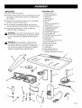
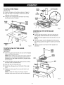
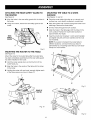
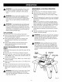
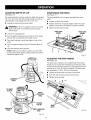
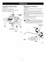
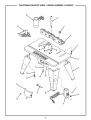
Operator's
Manual
II:RRFTSMRN I
ROUTER
TABLE
Double Insulated
Model No.
315.265030
_h
WARNING:
To reduce the risk of injury, the
user must read and understand the operator's
manual before using this product.
Customer
Help Line: t-800-932-3188
Sears, Roebuck and Co., 3333 Beverly Rd., Hoffman
Visit the Craftsman web page: www.sears.com/craftsman
983000-479
7-04
Save this manual
Estates, IL 60179 USA
for future
reference
•
Warranty ...........................................................................................................................................................................
2
•
Introduction ......................................................................................................................................................................
2
•
General Safety Rules ........................................................................................................................................................
3
•
Specific Safety Rules ........................................................................................................................................................
4
•
Symbols ........................................................................................................................................................................
•
Electrical ...........................................................................................................................................................................
•
Features ........................................................................................................................................................................
•
Assembly ..................................................................................................................................................................
10-13
•
Operation ..................................................................................................................................................................
14-17
•
Maintenance ...................................................................................................................................................................
•
Exploded View and Parts List ...................................................................................................................................
•
Parts Ordering/Service
...................................................................................................................................................
FULL ONE YEAR WARRANTY
5-6
7
8-9
18
20-21
22
ON CRAFTSMAN TOOL
If this CRAFTSMAN
tool fails to give complete satisfaction within one year from the date of purchase, RETURN IT TO
THE NEAREST SEARS STORE OR SEARS SERVICE CENTER IN THE UNITED STATES, and Sears will repair it, free
of charge.
If this CRAFTSMAN
of purchase.
tool is used for commercial
or rental purposes, this warranty applies for only 90 days from the date
This warranty gives you specific legal rights, and you may also have other rights which vary from state to state.
Sears, Roebuck and Co., Dept. 817WA, Hoffman Estates, IL 60179
This tool has many features for making its use more pleasant and enjoyable. Safety, performance, and dependability
been given top priority in the design of this product making it easy to maintain and operate.
have
_k
ALWAYS WEAR SAFETY GLASSES WITH SIDE
SHIELDS. Everyday eyeglasses have only impactresistant lenses; they are NOT safety glasses.
WARNING:
Read and understand all instructions. Failure to follow all instructions listed below,
may result in electric shock, fire and/or serious
personal injury.
SECURE WORK. Use clamps or a vise to hold work
when practical. It's safer than using your hand and it
frees both hands to operate tool.
READ ALL INSTRUCTIONS
•
KNOW YOUR POWER TOOL. Read the operator's
manual carefully. Learn the applications and limitations
as well as specific potential hazards related to this tool.
•
GUARD AGAINST ELECTRICAL SHOCK by preventing body contact with grounded surfaces. For example:
pipes, radiators, ranges, refrigerator enclosures.
•
KEEP GUARDS IN PLACE and in working order.
Never operate the tool with any guard or cover removed. Make sure all guards are operating properly
before each use.
•
REMOVE ADJUSTING KEYS AND WRENCHES. Form
habit of checking to see keys and adjusting wrenches
are removed from tool before turning it on.
•
KEEP THE WORK AREA CLEAN. Cluttered work
areas and work benches invite accidents.
•
DON'T USE IN DANGEROUS ENVIRONMENTS. Do
not use power tools near gasoline or other flammable
liquids, in damp or wet locations or expose them to
rain. Keep work area well lighted.
•
DO NOT OVERREACH.
balance at all times.
MAINTAIN TOOLS WITH CARE. Keep tools sharp and
clean for best and safest performance. Follow instructions for lubricating and changing accessories.
•
DISCONNECT ALL TOOLS. When not in use, before
servicing, or when changing attachments, blades, bits,
cutters, etc., all tools should be disconnected from
power source.
•
REDUCE THE RISK OF UNINTENTIONAL STARTING. Be sure switch is off when plugging in.
•
USE RECOMMENDED ACCESSORIES, Consult the
operator's manual for recommended accessories. The
use of improper accessories may cause risk of injury.
•
NEVER STAND ON TOOL. Serious injury could occur
if the tool is tipped or if the blade is unintentionally
contacted.
•
CHECK DAMAGED PARTS. Before further use of
the tool, a guard or other part that is damaged should
be carefully checked to determine that it will operate
properly and perform its intended function. Check for
alignment of moving parts, binding of moving parts,
breakage of parts, mounting and any other conditions
that may affect its operation. A guard or other part that
is damaged must be properly repaired or replaced by
an authorized service center to avoid risk of personal
injury.
•
DIRECTION OF FEED. Feed work into a blade or
cutter against the direction or rotation of the blade or
cutter only.
•
NEVER LEAVE TOOL RUNNING UNATTENDED,
TURN POWER OFF. Don't leave tool until it comes to
a complete stop.
KEEP CHILDREN AND VISITORS AWAY. All visitors
should wear safety glasses and be kept a safe distance
from work area.
•
MAKE WORKSHOP CHILDPROOF with padlocks,
master switches, or by removing starter keys.
•
DON'T FORCE THE TOOL. It will do the job better and
safer at the rate for which it was designed.
•
USE THE RIGHT TOOL. Do not force the tool or attachment to do a job for which it was not designed.
•
USE THE PROPER EXTENSION CORD. Make sure
your extension cord is in good condition. When using
an extension cord, be sure to use one heavy enough to
carry the current your product will draw. An undersized
cord will cause a drop in line voltage resulting in loss of
power and overheating. A wire gauge size (A.W.G.) of
at least 14 is recommended for an extension cord 25
feet or less in length. If in doubt, use the next heavier
gauge. The smaller the gauge number, the heavier the
cord.
• WEAR PROPER APPAREL. Do not wear loose
clothing, neckties, or jewelry that can get caught in the
tool's moving parts and cause personal injury. Nonslip
footwear is recommended when working outdoors.
Wear protective hair covering to contain long hair.
Keep proper footing and
• DON'TABUSECORD.Nevercarrytool bythecordor
yankitto disconnect
fromreceptacle.Keepcordfrom
heat,oil,andsharpedges.
• PROTECT
YOURLUNGS.Wearafaceordustmaskif
the cuttingoperationisdusty.
• PROTECT
YOURHEARING.
Wearhearingprotection
duringextendedperiodsofoperation.
• KEEPTOOL DRY, CLEAN, AND FREE FROM OIL
AND GREASE. Always use a clean cloth when cleaning. Never use brake fluids, gasoline, petroleum-based
products, or any solvents to clean tool.
•
INSPECT TOOL CORDS AND EXTENSION CORDS
PERIODICALLY and, if damaged, have repaired by a
qualified service technician. Stay constantly aware of
cord location and keep it well away from the rotating
wheel.
•
NEVER USE IN AN EXPLOSIVE ATMOSPHERE.
Normal sparking of the motor could ignite fumes.
•
USE ONLY OUTDOOR EXTENSION CORDS with
approved ground connection that are intended for use
outdoors and so marked.
_
•
KEEP HANDS AWAY FROM CUTTING AREA. Do not
reach underneath the table or in the cutting path with
your hands or fingers at any time while the tool is
connected to a power source.
•
DO NOT use awkward hand positions.
•
USE OVERHEAD GUARD WHEN ADJUSTABLE
FENCE IS NOT IN PLACE.
•
FIRMLY CLAMP OR BOLT THE ROUTER TABLE TO
A WORK SURFACE so that the router table surface is
approximately hip height.
•
INSPECT FOR AND REMOVE ALL NAILS FROM
LUMBER BEFORE ROUTING. Following this rule will
reduce the risk of serious personal injury.
•
DRUGS, ALCOHOL, MEDICATION. DO NOT
OPERATE TOOL WHILE UNDER THE INFLUENCE
OF DRUGS, ALCOHOL, OR ANY MEDICATION.
Following this rule will reduce the risk of electric shock,
fire, or serious personal injury.
•
SAVE THESE INSTRUCTIONS. Refer to them
frequently and use them to instruct others who may
use this tool. If you loan someone this tool, loan them
these instructions also.
WARNING"
Some dust created by power sanding, sawing, grinding, drilling, and other construction activities
contains chemicals known to cause cancer, birth defects or other reproductive harm. Some examples of these
chemicals are:
• lead from lead-based paints,
• crystalline silica from bricks and cement and other masonry products, and
• arsenic and chromium from chemically-treated lumber.
Your risk from these exposures varies, depending on how often you do this type of work. To reduce your exposure
to these chemicals: work in a well ventilated area, and work with approved safety equipment, such as those dust
masks that are specially designed to filter out microscopic particles.
Someof the followingsymbolsmaybeusedonthis tool. Pleasestudythemandlearntheirmeaning.Proper
interpretation
ofthesesymbolswillallowyouto operatethetool betterandsafer.
SYMBOL
NAME
DESIG NATION/EXPLANATION
V
Volts
Voltage
A
Amperes
Current
Hz
Hertz
Frequency (cycles per second)
W
Watt
Power
Minutes
Time
Alternating Current
Type of current
Direct Current
Type or a characteristic
no
No Load Speed
Rotational speed, at no load
[]
Class II Construction
Double-insulated
Per Minute
Revolutions, strokes, surface speed, orbits etc., per minute
Wet Conditions Alert
Do not expose to rain or use in damp locations.
Read The Operator's Manual
operator's
manual
before
To reduce the
risk of
injury,using
user this
mustproduct.
read and understand
min
"_
.../min
O
_,
@
@
@
®
Eye Protection
of current
construction
Always and
wearasafety
goggles
safety
glasses this
withproduct.
side
shields
full face
shield or
when
operating
Safety Alert
Precautions that involve your safety.
No Hands Symbol
Failure to keep your hands away from the blade will result in
serious personal injury.
No Hands Symbol
Failure to keep your hands away from the blade will result in
serious personal injury.
No Hands Symbol
Failure to keep your hands away from the blade will result in
serious personal injury.
No Hands Symbol
Failure to keep your hands away from the blade will result in
serious personal injury.
Hot Surface
To reduce the risk of injury or damage, avoid contact with
any hot surface.
Thefollowingsignalwordsandmeanings
areintendedto explainthe levelsofriskassociatedwiththisproduct.
SYMBOL
SIGNAL
MEANING
,_
DANGER:
Indicates an imminently hazardous situation, which, if not avoided, will
result in death or serious injury.
_k
WARNING:
Indicates a potentially hazardous situation, which, if not avoided, could
result in death or serious injury.
,_
CAUTION:
Indicates a potentially hazardous situation, which, if not avoided, may
result in minor or moderate injury.
CAUTION:
(Without Safety Alert Symbol) Indicates a situation
property damage.
SERVICE
Servicing requires extreme care and knowledge and
should be performed only by a qualified service technician. For service we suggest you return the product to
your nearest AUTHORIZED SERVICE CENTER for repair.
When servicing, use only identical replacement parts.
,_
A
that may result in
WARNING: To avoid serious personal injury, do
not attempt to use this product until you read
thoroughly and understand completely the
operator's manual. Save this operator's manual
and review frequently for continuing safe operation
and instructing others who may use this product.
WARNING:
The operation of any power tool can result in foreign objects being thrown into your eyes,
which can result in severe eye damage. Before beginning power tool operation, always wear
safety goggles or safety glasses with side shields and a full face shield when needed. We
recommend Wide Vision Safety Mask for use over eyeglasses or standard safety glasses with
side shields. Always use eye protection which is marked to comply with ANSI Z87.1.
SAVE THESE INSTRUCTIONS
DOUBLE
INSULATION
Double insulation is a concept in safety in electric power
tools, which eliminates the need for the usual three-wire
grounded power cord. All exposed metal parts are
isolated from the internal metal motor components with
protecting insulation. Double insulated tools do not need
to be grounded.
,_
WARNING:
The double insulated system is
intended to protect the user from shock resulting
from a break in the tool's internal insulation. Observe
all normal safety precautions to avoid electrical
shock.
NOTE: Servicing of a tool with double insulation requires
extreme care and knowledge of the system and should
be performed only by a qualified service technician. For
service, we suggest you return the tool to your nearest
authorized service center for repair. Always use original
factory replacement parts when servicing.
ELECTRICAL
CONNECTION
This tool has a precision-built electric motor. It should be
connected to a power supply that is 120 volts, 60 Hz,
AC only (normal household current). Do not operate
this tool on direct current (DC). A substantial voltage drop
will cause a loss of power and the motor will overheat. If
your tool does not operate when plugged into an outlet,
double-check the power supply.
EXTENSION
CORDS
When using a power tool at a considerable distance from
a power source, be sure to use an extension cord that has
the capacity to handle the current the tool will draw. An
undersized cord will cause a drop in line voltage, resulting
in overheating and loss of power. Use the chart to determine the minimum wire size required in an extension cord.
Only round jacketed cords listed by Underwriter's Laboratories (UL) should be used.
When working outdoors with a tool, use an extension
cord that is designed for outside use. This type of cord is
designated with "WA" on the cord's jacket.
Before using any extension cord, inspect it for loose or
exposed wires and cut or worn insulation.
**Ampere rating
(on tool faceplate)
0-2.0
2,1-3.4
Cord Length
3.5-5.0
5.1-7.0
7.1-12.0
12,1-16.0
Wire Size (A,W.G.)
25'
16
16
16
16
14
14
50'
16
16
16
14
14
12
100'
16
16
14
12
10
--
**Used on 12 ga_e - 20 amp c_uit.
NOTE: AWG = American Wire Gauge
A
WARNING:
Keep the extension cord clear of the
working area. Position the cord so that it will not get
caught on lumber, tools or other obstructions while
you are working with a power tool. Failure to do so
can result in serious personal injury.
A
WARNING:
Check extension cords before each
use. If damaged replace immediately. Never use tool
with a damaged cord since touching the damaged
area could cause electrical shock resulting in serious
injury.
PRODUCT
SPECIFICATIONS
Miter Slot ........................................
Table Dimensions ............ 14 in. x 24 in. (35.6 cm x 61 cm)
Maximum Cutter Diameter .................. 1-15/16 in. (4.9 cm)
Fence Width ........................................
3/8 in x 3/4 in. x 24 in.
(0.9 cm x 1.9 cm x 61 cm)
16-3/8 in. (41.6 cm)
Input ................................................
120 V, 60 Hz, AC only
Net Weight ..................................................
20 Ibs. (9.1 kg)
CUTTERGUARD
ASSEMBLY
FENCEASSEMBLY
MITER GAUGE
SWITCH
KEY
SWITCH
FRONTVIEW
REARVIEW
Fig. 1
KNOW YOUR
ROUTER
TABLE
See Figure 1.
Before attempting to use this product, familiarize yourself
with all operating features and safety rules.
CUTTER
GUARD
ASSEMBLY
The cutter guard assembly provides a barrier to protect
the operator from contact with the cutter and is adjustable
for all types of cuts and materials. The cutter guard also
doubles as a vacuum attachment. You can insert a
standard shop vacuum into the top of the clear plastic
cutter guard to keep dust to a minimum.
FENCE ASSEMBLY
The fence assembly provides an adjustable surface to
support and guide the work.
MITER GAUGE
A miter gauge is used for mitered routing and to help
support wider pieces.
STARTING
PIN
When you are unable to use the fence for a guide because
the workpiece is odd-shaped or too small, use the starting pin for a guide. Only use piloted cutters when using
the starting pin. Remove the fence and miter gauge when
using the starting pin.
SWITCH
This product is equipped with a power switch that has a
built-in locking feature. This feature is intended to prevent
unauthorized and possible hazardous use by children and
others. If you remove the key during operation, you can
turn the switch off, but you may not turn it on again until
you replace the key.
THROAT
PLATES
Five throat plates are included with the router table. The
throat plate provides a stable support surface around the
cutter and prevents objects from falling through the throat
and damaging the spindle.
UNDERTABLE
AND REAR SAFETY
GUARDS
The undertable guard and rear safety guard ensure that
your hand, loose clothing, and other objects do not come
in contact with the cutter or collet during operation.
_k
WARNING:
The undertable and rear safety guards
must be securely in place before using the router
table. Failure to do so could result in serious personal injury.
UNPACKING
PACKING
This product requires assembly.
1. Router table top (1)
2. Miter gauge knob (1)
3. Washer (1)
4. Miter gauge (1)
5. Hex key (1)
6. Bar (1)
7. Switch box assembly (1)
8. Guard post (1)
9. Cutter guard assembly (1)
10. Undertable guard (1)
11. Carriage bolt (2)
12. Socket head screw (16)
13. Lock washer (19)
14. Flat head machine screw (3)
15. Small screw (2)
16. Starting pin
17. Pan head machine screw (2)
18. Fence assembly (1)
19. Fence lock knob (2)
20. Throat plate (5
21. Table leg (4)
22. Rear safety guard (1)
23. Socket head screw (3)
Operator's Manual (not shown)
•
Carefully remove the tool and any accessories from the
box. Make sure that all items listed in the packing list
are included.
•
Inspect the tool carefully to make sure no breakage or
damage occurred during shipping.
•
Do not discard the packing material until you have
carefully inspected and satisfactorily operated the tool.
•
If any parts are damaged or missing, please call
1-800-932-3188 for assistance.
_i
WARNING:
If any parts are missing do not operate
this tool until the missing parts are replaced. Failure
to do so could result in possible serious personal
injury.
A
WARNING:
Do not attempt to modify this tool
or create accessories not recommended for use
with this tool. Any such alteration or modification is
misuse and could result in a hazardous condition
leading to possible serious personal injury.
LIST
1
21
2O
18
3
18
10
22
23
_
11
o r-'15
13
5
12
Fig. 2
10
,_
WARNING:Donotconnectto powersupplyuntil
assemblyis complete.Failureto complycouldresult
inaccidentalstartingandpossibleseriousinjury.
ASSEMBLING
THE ROUTER
SWITCH
ASSEMBLY
TABLE
SWITCH
When you remove the parts and hardware from the packing materials, check all items with the packing list and
drawing. If you are unsure about the description of any
part, refer to the drawing. If any parts are missing, delay
assembling until you have obtained the missing part(s).
TO ATTACH
CUTOUT
THE LEGS
See Figure 3.
•
Place router table top upside down on a flat, level
surface with the front edge closest to you.
•
Place each leg in a corner of the table.
NOTE: The leg with the switch cut-out should be
placed in the front left corner of the table. The leg with
the warning label should be placed in the front right
corner of the table.
•
Align the holes in the legs with the threaded holes in
the table.
•
Use the hex key provided, secure each leg with the
socket head screws and lock washers.
Fig. 4
TO ATTACH THE UNDERTABLE
See Figure 5.
•
Position the undertable guard around the throat of the
table.
•
Align the three holes of the guard with the threaded
holes in the table.
•
Use the hex key provided to secure the undertable
guard with the socket head screws and lock washers.
•
Turn the router table upright and be sure the table is
stable and rests securely on all four legs.
LOCK
WASHER
SOCKET
HEAD
SCREWS
UNDER
TABLE
GUARD
'_
I
Fig. 3
TO ATTACH
THE SWITCH
ASSEMBLY
i
See Figure 4.
•
Hold the switch assembly so that the words ON and
OFF on the toggle switch are upside down.
•
Place the switch assembly against the cutout in the left
front leg.
•
Align the small holes in the mounting tabs with the
small holes in the leg.
•
Using a phillips screwdriver, secure the switch
assembly to the leg with the small screws.
GUARD
&
THROAT
11
Fig. 5
TO ATTACH THE FENCE
See Figure 6.
•
Position the fence on the tame as shown in figure 6.
•
Align the ho(es on the bottom of the fence with the
channe(s on the router tame.
•
Using the two carriage bolts and fence lock knobs,
secure the fence to the tame.
BLACK.CUTTER
KNOB
TO
LOOSEN
GUARD
POST
BLACK
KNOB
GUARD
,_1_T TO
IGHTEN
FENCE
LOCK
KNOBS
FENCE
Fig. 7
FENCE
ASSEMBLING
THE MITER GAUGE
See Figure 8.
•
Position the miter gauge on the bar by placing the
miter gauge under the indicator and over the post.
NOTE: The miter gauge should rest securely on top of
the bar.
•
i
CARRIAGE
BOLT
•
Fig. 6
TO ATTACH THE CUTTER
ASSEMBLY
Place the washer over the threaded hole then screw
the miter gauge knob through the washer and into the
hole.
Tighten securely by turning the miter gauge knob
clockwise
GUARD
GAUGE
MITER
KNOB
See Figure 7.
•
Screw the guard post securely into one of the threaded
holes on the top of the fence.
I
NOTE: When the fence is close to the cutter, place the
guard post in the off-center threaded hole to provide
protection from the cutter and allow for proper suction
for the vacuum.
•
Loosen the plastic ring on the cutter guard by turning
the black knob counterclockwise.
•
Slide the ring over the guard post.
•
Center the cutter guard over the throat of the router
table.
•
Tighten the cutter guard by turning the black knob
clockwise.
MITER
/
GAUGE
POST_BAR
NOTE: To keep saw dust to a minimum, attach a
standard shop vacuum to the top of the cutter guard.
Fig. 8
12
ATTACHING THE REAR SAFETY GUARD
THE ROUTER
TO
MOUNTING
SURFACE
THE TABLE TO A WORK
See Figure 9.
See Figures 11 and 12.
•
Align the holes in the rear safety guard with the holes in
the router.
•
Place the router table right side up on a sturdy work
surface (e.g., work stand, workbench, counter top).
•
Using two screws, secure the rear safety guard to the
router.
•
Mark the surface with a pencil through the holes in the
table legs. Remove the router table.
•
Drill four holes through the work surface.
•
Align the holes in the table legs with the holes in the
work surface. Position the router table surface at
approximately hip height.
•
Insert four bolts (not included, 1/4-20 recommended)
and tighten securely with lock washers and hex nuts
(not included).
REAR
SAFETY
GUARD
NOTE: If you plan to transport the router table to
different locations, we recommend you attach it
permanently to a mounting board that you can easily
clamp to a work surface.
Fig. 9
MOUNTING
THE ROUTER
TO THE TABLE
See Figure 10.
Mount the router to the router table after the router table
has been completely assembled and the rear safety guard
has been installed on the router.
•
Hold the router upside down so that the front of the
router faces you.
•
Align the holes in the center of the table with the holes
in the router.
•
Holding the router with one hand, securely tighten each
of the three screws as shown in figure 10.
I
i
e
Fig. 11
FRONTOF
ROUTER
Fig. 10
Fig. 12
13
_
PERFORMING
WARNING"
Do not allow familiarity with your tool
to make you careless. Remember that a careless
fraction of a second is sufficient to inflict serious
_
WARNING:
Always wear safety goggles or safety
glasses with side shields when operating power
tools. Failure to do so could result in objects being
thrown into your eyes resulting in possible serious
injury.
Read the entire 175100 Router Operator's
•
Adjust the cutter guard so that it will not come in
contact with the workpiece or cutter during a cutting
operation.
result in serious personal injury.
APPLICATIONS
You may use this tool for the purposes listed below:
•
Adjust the infeed fence to support the uncut workpiece
and adjust the outfeed fence to support the workpiece
after the cut.
•
Piloted cutter operations using the starting pin for
edging patterned surfaces on wood and wood
composition materials
USING THE ROUTER
TABLE
•
Always plug the router into the router table switched
outlet. Never plug a router table mounted router into
another power source.
Lock-on the router switch. Refer to the 175100 router
manual for details,
•
Make sure the router table switch is off. Remove the
switch key.
•
Plug the router table power cord into a power source.
•
Always control the power to the router with the router
table switch whenever the router is mounted on the
table.
Feed the workpiece from right to left with the cutter
located in the fence opening.
WARNING:
The direction of feed for the workpiece
is always against the sharp edges of the cutter and
therefore into the rotation of the cutter. Failure to
WARNING:
When operating the router with the
router table, the router must only be plugged into
and controlled by the router table switched outlet.
To reduce the risk of serious personal injury, never
connect the table mounted router into another power
source.
CUTTER
GUARD
Manual.
•
•
A
Observe the following rules when using the router with the
router table.
Read the entire 175100 Router Operator's
Reconfirm that all router adjustments are securely
locked before connecting the router table to a power
source.
feed the work into the cutter correctly can result in
serious personal injury.
WITH THE ROUTER
•
•
A
• Table mounted dado and mortise operations in wood
and wood composition materials
Fence guided edging operations for cabinetry and
picture framing on wood and wood composition
materials
Manual.
NOTE: The workpiece must always be tight against
the fence, unless you are using a ball-bearing piloted
cutter. Additionally, it may be necessary to remove the
center fence plate if using large cutters up to 2 1/4 in.
not use any attachments or accessories not recommended by the manufacturer of this tool. The use of
attachments or accessories not recommended can
_
•
WARNING"
Current
and accessories
available for use
with attachments
this tool are listed
above. Do
•
OPERATION
See Figure 13,
injury.
,_
A ROUTING
WORKPIECE
INFEEDFENCE
OUTFEED
FENCE
WARNING: When using a router table, larger router
bits should be used for edging only. Do not use
router bits that are larger in diameter than the opening in the router table.
Fig. 13
14
INSERTING/REMOVING
CUTTERS
INSERTING
THROAT
PLATES
See Figure 14.
See Figure 15.
•
The throat plate provides a stable surface around the
cutter and prevents objects from falling through the throat
and damaging the spindle.
_
Unplug the router and the router table.
WARNING:
To prevent damage to the spindle or
spindle lock, always allow the motor to come to a
complete stop before engaging the spindle lock.
•
Remove the screws from the rear safety guard.
•
Remove the rear safety guard from the router.
•
Follow the directions for installing and removing cutters
in the 175100 router.
,_k
WARNING:
Use this router table only with the
175100 router. Do not attempt to use any other
router with this table. Failure to heed this warning
could result in improper operation of the tool and
serious personal injury.
•
Return the rear safety guard to its proper position.
•
Secure the rear safety guard by inserting and tightening
the two screws previously removed.
_k
The proper size throat plate depends on the size and
shape of the cutter. When inserted, the throat plate
opening should be within approximately 1/4 in.
(6.4 mm) of the outermost edge of the cutter.
•
Position the throat plate over the throat opening in the
router table.
•
Align the tab in the throat plate with the slot in the
throat opening.
•
Snap throat plate down and into place as shown.
NOTE: To remove throat plate, pull gently until the
throat plate snaps out.
THROAT
PLME
WARNING:
If you are changing a cutter immediately after use, be careful not to touch the cutter or
collet with your hands or fingers. They will get
burned because of the heat buildup from cutting.
Always use the wrench provided.
CUTTER
WRENCH
COLLETNUT
TO LOOSEN
COLLETNUT
SLOT
Fig. 15
TOTIGHTEN
COLLETNUT
DEPRESS
SPINDLELOCK
Fig. 14
15
ADJUSTING
DEPTH
OF CUT
POSITIONING
THE FENCE
See Figure 16.
See Figure 17.
We recommend that cuts be made at a depth not exceeding 1/8 in. (3.2 mm) and that several passes be made to
reach depths of cut greater than 1/8 in. (3.2 mm).
The fence enables you to support and guide the workpiece.
•
Loosen the fence lock knobs.
•
•
Position the fence the proper distance from the cutter
based on the amount of material you plan to remove.
•
Tighten the fence lock knobs.
Unplug the router and the router table.
,_
WARNING:
Failure to unplug the router and router
table could result in accidental starting causing
serious injury.
•
Unlock the clamping lever.
•
Turn the depth adjusting ring until the tip of the cutter
touches the work surface (zero depth of cut).
•
Turn depth indicator ring to zero depth of cut on the
scale.
•
Turn the depth adjusting ring to the desired depth of
cut.
•
Lock the clamping lever securely.
FENCELOCK
KNOBS
FENCELOCK
KNOBS
NOTE: When you use certain cutters, you may need
to remove the black plastic subbase from the router to
achieve full depth of cut.
Fig. 17
ADJUSTING
THE STEP RISERS
See Figure 18.
The step risers, located on the outfeed side of the fence,
enable you to support the workpiece as it exits the cutter.
The step risers provide support for routing operations that
remove up to 1/8 in. (3.2 mm) of material. The step risers
are adjustable in 1/32 in. (0.8 mm) increments.
•
Loosen the knob bolts on the rear of the fence.
•
Push the riser forward and toward the throat.
•
Tighten the knob bolts.
CLAMPING
LEVER
TO LOWER
CUTTER
\
i
KNOB
BOLTS
/
INDICATOR
POINT
Fig. 18
Fig. 16
16
ADJUSTING
THE MITER GAUGE
INSERTING
THE STARTING
PIN
See Figure 19.
See Figure 20.
•
Loosen the miter gauge knob.
•
Rotate the miter gauge to the desired angle.
The purpose of the starting pin is to act as a guide with
piloted bits.
•
Tighten the miter gauge knob.
Place the starting pin on the router table and use it as a
pivot point when cutting small, odd-shaped pieces.
NOTE: Do not use the fence when you are using the starting pin. Additionally, only use piloted cutters when using
the starting pin.
MITER GAUGE
KNOB
•
Place the starting pin into the threaded hole to the right
of the router table throat opening.
•
Turn the pin clockwise to secure.
,_
WARNING:
Using the fence when using the start
pin can result in the work binding and kicking back
resulting in serious personal injury. Do not use the
fence or miter gauge when using the starter pin.
STARTINGPIN
TO LOOSEN
MITER GAUGE
Fig. 19
: TOTIGHTEN
o
Fig. 20
17
_k
WARNING:
When servicing, use only identical
Craftsman replacement parts. Use of any other parts
may create a hazard or cause product damage.
_k
WARNING:
Always wear safety goggles or safety
glasses with side shields during power tool operation
or when blowing dust. If operation is dusty, also wear
a dust mask.
GENERAL
Electric tools used on fiberglass material, wallboard,
spackling compounds, or plaster are subject to accelerated wear and possible premature failure because the
fiberglass chips and grindings are highly abrasive to bearings, brushes, commutators, etc. Consequently, we do not
recommended using this tool for extended work on these
types of materials. However, if you do work with any of
these materials, it is extremely important to clean the tool
using compressed air.
MAINTENANCE
LUBRICATION
Avoid using solvents when cleaning plastic parts. Most
plastics are susceptible to damage from various types of
commercial solvents and may be damaged by their use.
Use clean cloths to remove dirt, dust, oil, grease, etc.
All of the bearings in this tool are lubricated with a sufficient amount of high grade lubricant for the life of the unit
under normal operating conditions. Therefore, no further
lubrication is required.
_k
Only the parts shown on the parts list are intended to be
repaired or replaced by the customer. All other parts
should be replaced at a Sears Service Center.
WARNING:
Do not at any time let brake fluids,
gasoline, petroleum-based products, penetrating
oils, etc., come in contact with plastic parts.
Chemicals can damage, weaken or destroy plastic
which may result in serious personal injury.
18
19
CRAFTSMAN
ROUTER
TABLE - MODEL
NUMBER
315.265030
•
22
21
2O
18
14
13
7
11
10
12
2O
•
CRAFTSMAN
ROUTER
TABLE-
MODEL
NUMBER
315.265030
•
J
The
modelmodel
number
number
in allwill
correspondence
be found on a regarding
plate attached
your ROUTER
to the motor
TABLE
housing.
or when
Always
ordering
mention
repair
the parts. |
SEE BACK
KEY
PART
NO,
NO,
PAGE FOR PARTS
ORDERING
INSTRUCTIONS
DESCRIPTION
QTY,
1
690559001
Guard Post ...........................................................
1
2
590378001
Lock Knob .............................................................
2
3
A310695005
Fence Assembly ....................................................
1
4
660141002
Carriage Bolt (M6 x 30 mm) ..................................
2
5
640736001
Router Table Top ...................................................
1
6
A310695003
Table Leg ...............................................................
3
7
660206025
Screw (M3.5 x 10 mm) ..........................................
2
8
303471-000
Switch Key ............................................................
1
9
A310695006
Switch Assembly ...................................................
1
10
A310695004
Front Leg ...............................................................
1
11
680873003
Hex Key .................................................................
1
12
660683001
Screw (6-32 x 3/8 in.) ............................................
2
13
512575001
Rear Safety Guard .................................................
1
14
590371001
Undertable Guard ..................................................
1
15
660686001
Socket Head Screw (M6 x 19 mm) ..................... 16
16
690558001
Lock Washer (M6) ...............................................
17
660169041
Socket Head Screw (M6 x 12 mm) ........................ 3
18
660684001
Flat Head Machine Screws (10-32 x 3/4 in.) ......... 3
19
620216001
Starting Pin ............................................................
1
20
512574001
Throat Plate A, 2 in ................................................
1
512574002
Throat Plate B, 1-1/2 in .........................................
1
512574003
Throat Plate C, 1-1/4 in .........................................
1
512574004
Throat Plate D, 1 in ................................................
1
512574005
Throat Plate E, 1/2 in .............................................
1
21
A310695008
Miter Gauge Assembly ..........................................
1
22
A310695007
Cutter Guard Assembly .........................................
1
983000-479
Operator's
Manual
21
19
Your Home
For repair-in
your home-of
all major brand appliances,
lawn and garden equipment, or heating and cooling systems,
no matter who made it, no matter who sold it!
..................
For the replacement parts, accessories and
owner's manuals that you need to do-it-yourself.
..................
For Sears professional installation of home appliances
and items like garage door openers and water heaters.
..................
1-8 00-4-MY-H 0 ME® (1-800-469-4663)
oa,,
an t, o, o,oht sod
Oaoada
www.sears.com
..........
www.sears.ca
Our
Home
For repair of carry-in items like vacuums, lawn equipment,
and electronics, call or go on-line for the location of your nearest
Sears Parts & Repair Center.
1-800-488-1222
Call anytime,
day or night (U.S.A. only)
www.sears.com
To purchase a protection agreement (U.S.A.)
or maintenance agreement (Canada) on a product serviced
1-800-827-6655
Pard pedir servicio
(U.S.A.)
1-800-361-6665
de reparacien
Au Canada
a domicilio, y para ordenar piezas.
1-8 8 8-S U- HO G AR sM
by Sears:
(Canada)
pour service en frangais:
1 -800- LE- FO YER Mc
(1-800-533-6937)
(1-888-784-6427)
www.sears.ca
...............
..............
SEARS
® Registered
Trademark
/ TMTrademark
/
SM
Service
Mark of Sears,
Roebuck
® Marca Registrada
/ TM Marca de F_brica / SM Marca de Servicio
de Sears,
MC
Marque
de commerce
/ MD Marque
d6pos6e
de Sears,
Roebuck
and Co.
and Co.
Roebuck
and
Co.
® Sears,
Roebuck
and Co.