1
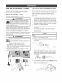
Operator's Manual
®
3100 PSi MAX
2.8 GPM MAX
Model No. 580.752080
wAReeeG
Before using this product, read this
manual and follow atI Safety Rutes
and Operating Instructions.
®Safety
®AssembJy
ADVER'rENCmA®Operation
,, Maintenance
Antes de utiiizar el producto, Iea este
®Parts
manuai y siga todas Ias Reglas de
Seguridad e Instrucciones de Uso.
Sears, Roebuck and Co., Hoffman Estates, [L 68179 U.S.A.
Visit our Craftsman website: www.craftsman.eom
Part No. 203794GS Draft - (04/02/2007)
,, Espa_oi, p. 34
o J!
WARRANTY..........................................
SAFETYRULES......................................
2
2-5
FEATURES
ANDCONTROLS
..............................
ASSEMBLY
........................................
6
7-10
OPERATION
.......................................
SPECIFICATIONS
.....................................
11-15
16
MAINTENANCE
....................................
17-2!
STORAGE...........................................
22
TROUBLESHOOTH'_IG
..................................
23
REPLACEMENTPARTS..............................
24-31
EMISSION CONTROLWARRANTY .....................
32-33
ESPA__OL
.........................................
34-59
HOW TO ORDERPARTS ........................
BACKPAGE
If this pressure washer faiis due to a defect in materiai or workmanship within one year from the date of purchase, return it to
any Searsstore, other Craftsman outlet, or Sears Parts & Repair Center in the United States or Canadafor free repair (or
replacementif repair proves impossible).
Ali warranty coverage applies for only 90 days from date of purchase if this pressure washer is ever used for commercial or
rentai purposes.
This warranty gives you specific legal rights, and you may also have other rights which vary from state to state.
Sears, Roebuck and Ce,, Heffman Estates, JL 68179
Sears Canada Jnc,, Terente, 8ntarie,
Canada MSB 2B8
This is the safety alert symbol, tt is used to alert yea to potential persenaminjary hazards. Obey aH safety messages
that fellow this symbemto avoid pessiNe injury or death.
_Read
this pressurewasher.
manual carefully and
become
familiar
..... with your
Knew
its applications,
its limitations, and any hazards involved.
Hazard SymhoJsand Nteanings
The safety alert symboi (,_) is used with a signal word
(DAr/GER, CAUTIOr/,WARNING), a pictorial and/or a safety
messageto alert you to hazards. BANGERindicates a hazard
which, if not avoided, wi/'/resuIt in death or serious injury.
WARNINGindicates a hazard which, if not avoided, cou/d
result in death or serious injury. CAUTtONindicates a hazard
which, if not avoided, might result in minor or moderate
injury. NOTICEindicates a situation that could result in
equipment damage. Foiiow safety messages to avoid or
reduce the risk of injury or death.
Toxic Fumes
Hazardous Chemical
Electrical Shock
SlipperySurface
Fall
FluidInjection
Fire
Moving Parts
© Sears Brands, LLC
Explosion
Flying Objects
Operator'sManual
Kickback
Hot Surface
WARNING
Fuel and its vapors are extremely flammable and
explosive.
death.
Fire or explosion can cause severe burns or
Contents
areharmful
orfatalif swailowed.
Avoid
contact
toeyes,skinorclothing.
DONOT
take
internaiiy.
Avoidbreathing
themistorvapor.
Overexposure
toeyesorskincancause
irritation.
Keep
stabilizer
outofthereach
ofchiidren.
Fueistabiiizer
isahazardous
chemical.**
", Fresh StartTM fuel cap is designed to hold a cartridge which
contains fuel stabilizer.
o If SWALLOWED,call physician immediately. DO NOT induce
vomiting. If inhaled, remove to fresh air. hs case of eye or skin
contact, flush with water for 15 minutes.
o Store unopened cartridges in a cool, dry, well ventilated area.
Keep open cartridge in fuel cap, and fuel cap c!osed on fuel tank
when not in use.
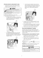
WHEN ADDmNGOR DRAiNiNG FUEL
• Turn pressure washer OFFand let it cool at least 2 minutes
before removing fuel cap. Loosen cap slowly' to relieve pressure
in tank.
• Fill or drain fuel tank outdoors.
o DO NOT overfill tank. Allow space for fuel expansion.
• If fuel spills, wait until it evaporates before starting engine.
o Keep fuel away frorn sparks_ open flames, pilot lights_ heat, and
other ignition sources.
o DO NOT light a cigarette or smoke.
WHENSTARTINGEQUmP_dENT
• Ensure spark plug, muffler, fuet cap, and air cleaner are in
place.
o hsthe case of an emergency, contact a physician immediately
and call 1-800-424-9300 for material safety inforrnation.
• DO NOTcrank engine with spark plug removed.
WHEN OPERATINGEQUIPI_IENT
**Fuel stabilizer contains: 2,6-di-tret-butylphenol (128-39-2) and aliphatic petroleum
distillate (64742-47-8),
o DO NOT tip engine or equipment at angle which causes fuel to
spill.
WARNING
Running engine gives off carbon monoxide, an
odoriess, coloriess, poison gas.
Breathing carbon monoxide can cause headache,
fatigue, dizziness, vomiting, confusion, seizures,
nausea, fainting or death.
Some chemicais or detergents may be harmful if
inhaied or ingested, causing severe nausea,
fainting, or poisoning.
• OperatepressurewasherONLYoutdoors.
• Keepexhaustgasfrom elsteringa confinedareathrough
windows,doors,ventilationintakes,or otheropenings.
o DONOTsta!t or run engineindoorsor in an enclosedarea,
evenif windowsanddoorsare open.
o Usea respiratoror rnaskwheneverthereis a chancethat
vapors rnaybe inhaled.
• Readall instructionswith maskso you arecertainthe maskwill
providethe necessaryprotectionagainstinhalingharmful
vapors.
• DO NOT spray flammable liquids.
WREN TRANSPORTmNG
OR REPAiRmNG
EQUiPI'_IENT
• Transport/repair with fuet tank EMPTYor with fuel shutoff valve
OFF.
• Disconnect spark plug wire.
WHEN STORmNGFUEL OR EQUiPIVlENTWiTH FUEL mNTANK
o Store away from furnaces, stoves, water heaters, clothes
dryers, or other appliances that have pilot light or other ignition
source becausethey can ignite fuet vapors.
WARNING
Risk of electrocution=
Contact with power source can cause etectric
shock or burn,
• NEVERspray near power source.
WARNING
WARNING
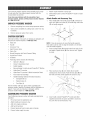
Starter cord kickback (rapid retraction) can result
in bodily injury. Kickback will pulI hand and arm
toward engine faster than you can Iet go.
The high pressure stream of water that thb
equipment produces can cut through skin and its
underlying tissues, ieading to serious injury and
_ossible amputation.
Broken bones, fractures, bruises, or sprains
could result.
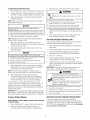
• NEVERpull starter cord without first relieving spray gun
pressure.
o When starting engine_pull cord slowly until resistance is felt
and then pull rapidly to avoid kickback.
Spray gun traps high water pressure, even when
engine is stopped and water is disconnected,
which can cause injury.
• DO NOT allow CHILDRENto operate pressure washer.
o NEVERrepair high pressure hose. Replaceit.
o After eachstarting atternpt where engine fails to run, always
point spray gun in safe direction press red button and squeeze
spray gun trigger to releasehigh pressure.
• NEVERrepair leaking connections with sealant of any kind
Replaceo-ring or seal
o Firmly grasp spray gun with both hands when using high
pressure spray to avoid iniury when spray gun kicks back.
• Keep high pressure hose connected to purnp and spray gun
while system is pressurized.
WARNING
o NEVERconnect high pressure hoseto nozzle extension.
• ALWAYS point spray gun in safe direction, press red button
and squeezespray gun trigger, to release high pressure, every
tirne you stop engine.
• NEVERaim spray guts at people, animals, or plants.
Use of pressure washer can create puddles and
slippery surfaces,
o DO NOTsecure spray gun in open position.
Kickback from spray gun can cause you to fall,
o NEVERuse a spray gun wlsich does not have a trigger lock or
trigger guard in place and in working order.
* Operate pressure washer frorn a stable surface.
o The cleaning area should haveadequate slopes and drainage to
reduce the possibility of a fall due to slippery surfaces.
• DO NOT leave spray gun unattended while rnacbine is running.
• Always be certain spray gun, nozzbs and accessories are
correctly attached.
o Be extremely careful if you rnust use the pressure washer from
a ladder, scaffolding, or any other similar location.
WARNING
o Firmly grasp spray gun with both hands when using high
pressure spray to avoid injury when spray gun kicks back.
Unintentional sparking can result in fire or
WARNING
'_¢
electric shock.
Contact with muffler area can result in serious
burns.
WHENADJUSTmNGOR MAKING REPAIRSTO YOUR PRESSURE
WASHER
Exhaustheat/gases can ignite combustibles,
structures or damage fuel tank causing a fire.
• Disconnect the spark plug wire frorn the spark plug and place
the wire where it cannot contact spark plug.
WHENTESTmNG
FOR ENGINESPARK
* DO NOTtouch hot parts and AVOID hot exlsaustgases.
* Allow equipment to cool before touching.
o Keep at least 5 feet (152 crn) of clearance on all sides of
pressure washer including overhead.
o Code of Federal Regulation (CFR)Title 36 Parks, Forests, and
Public Property require equipment powered by an internal
combustion engine to have a spark arrester, rnaintained in
effective working order, complying to USDAForest service
standard 5100-1C or later revision. In the State of California a
spark arrester is required under section 4442 of the California
Public resources code. Other states rnay havesimilar laws.
• Use approved spark plug tester.
o DO NOT check for spark with spark plug removed.
WARNING
Starter and other rotating parts can entangie
hands, hair, clothing, or accessories.
• NEVERoperatepressurewasherwithoutprotectivehousingor
High pressure spray may damage fragiie items inciuding
lass.
DONOTpointspraygun at glasswhen usingMAX(0°) nozzle.
NEVERaim spraygun at plants.
covers.
• DONOTwea! looseclothing jewelryor anythingthat may be
caughtin the starteror other rotati_gparts.
o Tieup long hai!and rernovejewelry.
WARNING
IRisk of eye injury=
..L..__jSpray
can splash back or propel objects.
Alwayswearsafetygoggleswhenusingthis equipmentor in
vicinity of whereequipmentis in use.
Beforestartingthe pressurewasher,be sureyou are wearing
adequatesafetygoggles.
NEVERsubstitutesafetyglassesfor safetygoggles.
Improper treatment of pressure washer can damage it and
shorten its iife.
If you havequestionsaboutintendeduse,ask dealeror contact
Sears.
NEVERoperateunitswith brokenor missingpa!rs,or without
protectivehousingor covers.
DONOTby-passanysafetydeviceon this rnachine.
DONOTtamperwith governedspeed.
DONOToperatepressurewasheraboveratedpressure.
DONOTmodifypressurewasherin anyway.
Beforestartingpressurewasherin cold weathercheckall parts
of the equiprner_t
to besureice hasnot formedthere.
NEVERmovemachineby pullingon hoses.Usehandle
providedon unit.
Checkfuelsystemfor leaksor signs of deterioration,suchas
chafedor spongyhose,looseor missingclamps_or damaged
ta!_kor cap. Correctall defectsbeforeoperatingpressure
washer.
This equipmentis designedto be usedwith Searsauthorized
parts ONLY.If equipmentis usedwith partsthat DONOT
complywith minimumspecifications,userassumesall risks
and liabilities.
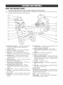
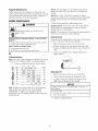
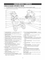
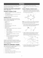
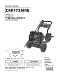
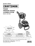
KNOWYOURPRESSUREWASHER
,r' F I-_Read the Operator's ManuaJ and safety rubs before operating your pressure washer.
.... Compare the illustrations with your pressure washer to familiarize yourself with the locations of various controls and
adjustments. Savethis manual for future reference.
A - HydroFoamTM Launcher-- Use to apply HydroFoamTM
wash or other detergents designed specifically for
pressure washers.
B o Project ProTM Nozzles -- Max, General,and Delicate
Nozzles:for various cleaning applications.
_1=Throttle Lever-- Sets engine in starting mode for recoil
starter and stops a running engine.
N =Detergent Siphoning Tube/Filter -- Use to siphon
pressure washer safe detergents into the low pressure
stream.
C - Spray Gun -- Controis the appiication of water onto
cleaning surface with trigger device, inciudes trigger lock.
P =Water thief -- Connection for garden hose.
O - Accessory Tray -- Provides convenient storage for
standard and optional accessories, such as brushes,
turbo wands, etc.
S - Automatb Cool Down System -- Cycles water through
pump when water reaches 125°-155°F. Warm water wiii
discharge from pump onto ground. This system prevents
internal pump damage.
R =Pamp -- Developshigh pressure.
E =Nigh Pressure Nose -- Connect one end to water pump
and the other end to spray gun.
T - Oil Drain-
F =Nozzle Extensionwith Quick Coeneot -- Allows you to
switch between four different nozzbs.
U oHigh Pressure OatJet-- Connection for high pressure
hose.
Q =Warning/Operating instructions Tag -- Identifies
hazards and proper procedure to start/stop pressure
washer.
V =Fuet Tank -- Fill tank with regular unleaded fuel. Always
ieave room for fuel expansion.
items Not Shown:
N =Choke Lever -- Preparesa cold engine for starting.
Drain engine oil here.
J - Air Filter -- Protects engine by filtering dust and debris
out of intake air.
Data Tag (near rear of base plate) -- Provides modei and
serial number of pressure washer, Pleasehave these readily
available if caliing for assistance,
J(- Recoil Starter -- Used for starting the engine manually.
Oil Fill -- Checkand add engine oii here=
L - Fael Valve -- Used to turn fuel supply on and off to
engine.
Safety Goggles -- Always usethe enclosed safety goggies
when running your pressure washer=
Yourpressure
washer
requires
someassembly
andis ready
foruseonlyafterit hasbeenproperly
serviced
withthe
recommended
oilandfuel.
Jfyou have any prohtemswith the assembly of your
pressurewasher, pmeasecall the pressurewasher hempline
at 1o800o222o3136.
7.
8.
Attach tlandJe and Accesse_ Tray
1.
UNPACKPRESSURE
WASHER
1.
Remove everything from carton except pressure washer.
2.
Open carton completely by cutting each corner from top
to bottom.
3.
Remove pressure washer from carton.
Attach nozzleextension to spray gun.
Sebct/attach quick connect ProjectProTM nozzleto nozzle
extension.
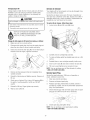
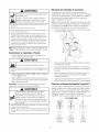
Placehandle (A) onto handle supports (B) connected to
main unit. Make sure holes (C) in handb align with holes
(C) on handle supports.
CARTONCONTENTS
Checkali contents, if any parts are missing or damaged, call
the pressure washer hetpline at 1=800=222=3136.
° Main Unit
°
Handle
o Accessory Tray
°
,
High Pressure Hose
Spray Gun
o
NozzleExtensionwith Quick Connect Fitting
,
°
HydroFoamTM Wash
Oil Bottle
,
Parts Bag (which includes the following):
o
Operator's Manual
,
Owner's Registration Card
,
Safety Goggles
o
Bagcontaining 3 multi-coiored ProjectProTM Nozzles
,
HydroFoamTM Launcher
,
HydroFoamTM Launcher & Wash Instruction Sheet
o
FreshStart Fuel Cartridge
,
HandieFasteningHardwareKit (which includes):
o Carriage Boits (2)
o
Plastic Knobs (2)
,
Tree Ciips (4)
NOTE:it may be necessary to move the handle supports
from side to side in order to align the handle so it will slide
over the handb supports.
2.
insert carriage bolts (A) through holes from back of unit
and attach a plastic knob (B) from front of unit. Tighten
by hand.
3.
Placeaccessory tray (A) over holes (C) on handte
(viewing from front of unit). Push the tree clips (B) into
the holes untii they sit fiat against the accessory tray.
4.
Insert multi-colored ProjectProTM nozzlesand other
suppiied accessories in spaces provided in accessory
tray. See How to Use Accessory Tray.
Becomefamiiiar with each piece before assembling the
pressure wasiser, identify aii contents with the iiiustration on
page 6. if any parts are missing or damaged, calI the
pressure washer helpline at 1=81}1}=222=3136.
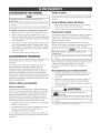
ASSEMBLINGPRESSUREWASHER
Your Craftsman pressure washer wJflneed assembly before
operation:
1.
Fiii out and send in registration card.
2.
3.
4.
Attach handle and accessory tray.
Add oii to engine crankcase.
Add fuel to fuel tank.
5.
Connect pressure hose to spray gun and pump.
6.
Connect water supply to pump.
Add Engine OiJ
1.
Place pressure washer on a fiat, bvei surface.
2.
Cleanarea around oii fiii and remove yeiiow oii fiii
cap/dipstick.
NOTE:See Oil Recommendations in Maintenancesection.
Verify provided oii bottle is the correct viscosity for current
ambient temperature.
3. Using oiI funnel (optional), slowiy pour contents of
provided oil bottie into oil fill opening.
Improper treatment of pressure washer can damage it and
shorten its life.
DONOTattemptto crankor startthe enginebeforeit hasbeen
properlyservicedwith the recommended
oil This may resultin
an enginefailure
4.
Replace oil fill cap/dipstick and fully tighten.
Add FueJ
Fuel must meet these requirements:
,
Clean, fresh, unleaded gasoline.
,
A minimum of 87 octane/87 AKi (91 RON). High altitude
use, see High A/titude.
,
Gasotinewith up to 10% ethanoi (gas@@ or up to 15%
MTBE (methyl tertiary butyl ether) is acceptable.
WARNING
FueIand its vapors are extremely fiammabb and
explosive.
death.
Fire or explosion can cause severe burns or
WHENADDmNG
FUEL
o TurnpressurewasherOFFand let it coolat least2 minutes
beforeremovingfuelcap. Loosencapslowly'to relievepressure
in tank.
o Fillfuel tankoutdoors.
• DONOToverfilltank.Allowspacefor fue! expansion.
o If fuel spills,wait until it evaporatesbeforestartingengine.
• Keepfuelawayfrom sparks,openflames,pilot lights,heat,and
otherignitionsources.
o DONOTlight a cigaretteor smoke.
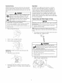
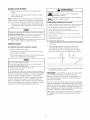
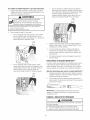
1.
Cieanarea around fuel fiii cap, remove cap.
2.
Siowiy add regular unleaded fuel (A) to fuet tank (B). Be
carefui not to overfiii. Aiiow about 1.5" (4 cm) (C) of tank
space for fuel expansion.
Avoid pressure washer damage.
Faiiureto foiiow Operator's Manuai for fuel
recommendations voids warranty.
DONOTuseunapprovedgasolinesuchas E85.
DONOTmix oil in gasoline.
DONOTmodifyengineto run on alternatefuels.
To protect the fuel system from gum formation, mix in a fuel
stabiiizer when adding fuel. See Storage. Ali fuel is not the
same. if you experience starting or performance probiems
after using fuel, switch to a different fuei provider or change
brands. This engine is certified to operate on gasoiine. The
emission control system for this engine is EM (Engine
Modifications).
CAUTION! AIcohoI-blendedfuels (caibd gas@oI, ethanoi or
methanol) can attract moisture, which leadsto separation and
formation of acids during storage. Acidic gas can damagethe
fuel system of an engine while in storage.
To avoid engine problems,the fueI system should be treated
with a fuel preserver or emptied before storage of 30 days or
longer, if adding a fuel preserver, fiii the fuei tank with fresh
fuel. if only partiaiiy filied, air in the tank wiii promote rue!
deterioration during storage, if fuet preserver is not used,
drain the rue! tank, start the engine and bt it run untii the fuel
fines and carburetor are empty. Use fresh fuel next season. See
Storagefor additionalinformation.
NEVERuseengine or carburetor cleaner products in the fuel
tank as permanent damage may occur.
FreshStart Fuel Cap
tti!lh llllitude
Adding fue! preserver helps keepfuei fresh and carburetors
clean for easier starting, ati season iong. This new fue! cap
automatically drips concentrated fuel preserver into your fuel
tank.
At altitudes over 5,000 feet (1524 meters), a minimum
85 octane / 85 AKi (89 RON)gasoiine is acceptable. To
remain emissions compiiant, high aititude adjustment is
required. Operationwithout this adjustment win cause
decreasedperformance, increased fuei consumption, and
increased emissions. See a qualified Sears deaier for high
altitude adjustment information. Operation of tile engine at
altitudes below 2,500 feet (762 meters) with the high altitude
kit is not recommended.
,, .DANGER
_///,,av/_ contact to eyes, skin or clothing. DONOTtake
internaliy. Avoid breathing the mist or vapor.
Overexposureto eyes or skin can cause irritation.
Keep stabiiizer out of the reach of children.
Fuel stabilizer is a hazardous chemical.**
Cennect Hose and Water $upply te Pump
If SWALLOWED,
callphysicianimmediately.
h_the caseof an emergency,contacta physicianimmediately
and call1-800-424-9300for materialsafetyirfforrnation.
*Fuel stabilizer contains: 2,6-di-tret-butylphenol (128-39-2) and aliphatic petroleum
distillate (64742-47-8),
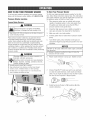
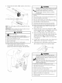
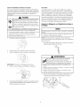
1.
Placecartridge into fuel cap.
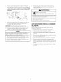
NOTE:Removeand discard the shipping caps from the
pump's high pressure outlet and water inlet before attaching
hoses.
1.
Uncoii higil pressure hose and attach one end of hose to
base of spray gun. Tighten by hand.
/
,/
jl
2.
Pushto <<snap"cartridge into place.
3.
Removetab to expose membrane.
!tYAilIIIItll
igh pressure stream
ent produces can cut through skin and its
ying tissues, ieading to serious injury and
le amputation.
NEVERconnecthigh pressurehoseto nozzleextension.
Keephigh pressurehoseconnectedto pumpand spraygun
whilesystemis pressurized.
Alwaysbe certainspraygun,nozzlesand accessoriesare
correctlyattached.
IMPORTANT:DO NOT remove the silver foil seal oll the
opposite side.
4.
Reinstall fuei cap on fuel tank.
.
Periodicaliy check the cartridge to ensure there is still
fuel stabilizer inside. If it is empty, remove cartridge and
replace=
Attach other end of high pressure hose to high pressure
outlet on pump, Tighten by hand,
.
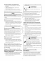
Before connecting garden hose to water inlet, inspect
inlet screen. Cleanscreen (A) if it contains debris or have
it replacedif damaged, DO NOTranpressurewasher if
inlet screen is damaged or missing.
6, Turn ONttle water, press red button on the gun and
squeezethe trigger to purge the pump system of air and
impurities.
Always wear safety goggles when using this equipment or in
vicinity of where equipment is in use.
Before starting the pressure washer, be sure you are wearing
adequate safety goggles.
NEVERsubstitute safety glasses for safety goggles.
4,
Run water through garden hose for 30 seconds to flush
it of debris. Turn off water,
ChecMist Befere Starting Engine
iMPORTANT: DO NOTsiphon standing water for the water
supply. Use ONLY cold water (less than IO0°F),
5,
Reviewthe unit to ensure you have performed all of the
following:
Connect garden hose (not to exceed 50 feet in length) to
water inlet. Tighten by hand.
1,
Be sure to read Safety Rules and Operationsections
before using the pressure washer.
Make sure handle is in place and secure,
NOTICE
2,
Using a One Way Vaive (vacuum breaker or check valve)
at pump inlet can cause pump or iniet connector damage.
ThereMUSTbeat leastten feet (3 m)of unrestrictedgarden
hosebetweenthe pressurewasherinletandanydevice,suchas
a vacuumbreakeror checkvalve.
3,
Checkthat eli has been added to proper level in engine
crankcase,
4.
Add proper fuet to fuet tank.
5.
Checkfor proper hose connections (high pressure and
water suppiy) and that there are no kinks, cuts, or
damageto the high pressure hose.
6.
Provide proper water supply (not to exceed IO0°F).
Damageto equipmentresultingfrom failureto follow this
instructionwill voidwarranty'.
10
HOWTO USEYOUR PRESSUREWASHER
To Start Your Pressure Washer
If you haveany problems operating your pressure washer,
please call the pressure washer helpline at 1-800-222-3136.
To start your engine=poweredpressure washer for the first
time, foiiow these instructions step=by=step.This information
also applies whenever you start the engine after you have let
the pressure washer sit idle for at bast a day.
Pressure Washer Lecatien
PressureWasherClearance
1.
Placepressure washer near an outside water source
capable of supplying water at a flow rate greater than
3.8 galions per minute and no iess than 20 PSi at
pressure washer end of garden hose.
2.
Checkthat high pressure hose is tightly connected to
spray gun and pump. See Assembyfor illustrations.
3.
Make sure unit is in a ievel position.
4.
Connectgarden hose to water inlet on pressure washer
pump.
5.
Turn ONthe water, press red button on the gun and
squeezethe trigger to purge the pump system of air and
impurities.
WARNING
Exhaustheat/gases can ignite combustibbs,
structures or damage fuei tank causing a fire.
o Keepat least5 ft. (152 crn)clearanceon all sidesof pressure
washerincludh_g
overhead.
Placepressure washer outdoors in an area that wiii not
accumulate deadly exhaust gas. DO NOT place pressure
washer where exhaust gas (A) could accumulate and enter
inside or be drawn into a potentiaily occupied building.
Ensureexhaust gas is kept away from any windows, doors,
ventiiation intakes, or other openings that can aliow exhaust
gas to coIiect in a confined area. Prevaiiingwinds and air
currents should be taken into consideration when positioning
_ressurewasher.
i
OTlCE
DO NOT run the pump without the water supply connected
and turned on.
instructionwill
void warranty
Damageto equipment
resultingfrom failureto followthis
WARNING
Running engine gives off carbon monoxide, an
odorless, colorless, poison gas.
Breathingcarbon monoxide can cause headache,
fatigue, dizziness, vomiting, confusion, seizures,
nausea, fainting or death.
° OperatepressurewasherONLYoutdoors.
o Keepexhaustgasfrornenteringa confinedareathrough
windows,doors,ventilationintakes,or otheropenings.
* DONOTstar or run engineindoorsor in an enclosedarea,
evenif windowsanddoorsare open.
6.
Attach nozzleextension to spray gun. Tighten by hand.
Choose ProjectProTM nozzleyou want to use, puff back
on coliar of nozzle extension, insert nozzle and reiease
coiiar. Tug on nozzle to make sure it is securely in place.
See How to Use ProjectProTMIVozz/eSystem.
8.
11
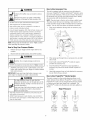
Rotate fuel shut-off valve to "On" position (A) (fully
counter=clockwise).
.
Move throttie lever (A) to "Fast" position, shown here as
a rabbit.
IIVAIIIIIIIIII
•
,
10. Move choke lever to "Choke" position.
,
°
Starter cord kickback (rapid retraction) can result
in bodily injury. Kickback will pull hand and arm
toward engine faster than you can iet go.
Broken bones, fractures, bruises, or sprains
could resuit.
NEVERpull startercord withoutfirst re/evingspraygun
pressure.
Whenstartingengine,pull cord slowlyuntil resistanceis felt
andthen pull rapidlyto avoidkickback.
After eachstartingattempt,whereenginefails to run, always
pointspraygun in safedirection,pressred buttonand squeeze
sprayguntriggerto releasehigh pressure.
Firmlygraspspraygun with both handswhenusing high
pressuresprayto avoidinjury whenspraygun kicks back.
/
NOTE:For a warm engine, be sure the choke lever is in the
"Run" position.
12. Return recoii starter siowiy. DO NOT let rope "snap
back" against starter.
iMPORTANT: Before starting the pressure washer, be sure
'ou are wearing adequatesafety goggles.
13. When engine starts, siowiy move choke iever to "Run"
position, as engine warms, if engine faiters, move choke
lever to "Choke" position, then to "Run" position.
WARNING
14. After each starting attempt, where engine fails to run,
always point gun in safe direction, press red button and
squeeze spray gun trigger to reieasehigh pressure.
Move choke Iever to "Choke" position, and repeat steps
11 througi_ 13.
>-_
Risk of eye injury.
• _
ISpray can splash back or propel objects.
Alwayswearsafetygoggleswhenusingthis equiprnentor in
vicinity of whereequipmentis in use.
Beforestartingthe pressurewasher,besureyou arewearing
adequatesafetygoggles.
NEVERsubstitutesafetyglassesfor safetygoggles.
15. If engine faiis to start after six pulis, move choke lever to
"Run" position, and repeatsteps 11 througil 13.
16. Point spray gun in a safe direction, push the red button
(A) to releasethe trigger lock, and puiI the trigger.
1 When starting engine, position yourself as
recommended, grasp handie and pu!I recoii starter
lightiy until you feel some resistance, then pulI briskiy.
/
-
_
/7,-
1
?,
--
IAIIIIIIIIII
The high pressure stream of water that this
equipment produces can cut through skin and its
J
_
)ossibte amputation.
nderlying tissues, ieading to serious injury and
Spray gun traps Hgh water pressure, even when
engine is stopped and water is disconnected,
which can cause injury.
• DONOTallowCHILDREN
to operatepressurewasher.
• Keephigh pressurehoseconnectedto purnpand spraygun
whilesystemis pressurized.
° NEVERaim spraygun at people,animals_or plants.
• DONOTsecurespraygun in openposition.
° DONOTleavespraygun unattendedwhilernachineis running.
• NEVERusea spraygun whichdoesnot havea triggerlock or
triggerguardin placeandin workingorder.
• Alwaysbe certainspraygun,nozzlesand accessoriesare
correctlyattached.
12
How te Use Accessory Tray
WARNING
The unit is equipped with an accessorytray with piacesto
store your ProjectProTM nozzles, HydroFoamTM iauncher, spray
gun and nozzleextension. There is aiso a hook at the front of
the accessorytray to hoid your high pressure hose. Identify
ali accessories with the iiiustration on page 6.
Contact with muffler area can result in serious
burns.
Exhaustheat/gases can ignite combustibles,
structures or damage fuel tank causing a fire.
NOTE:The extra hob in the tray is for storing a utiiity brush.
The extra clip in the tray is for storing a turbo nozzie. The
brush and turbo nozzle are NOT included with your pressure
washer. You can buy these items as optional accessories.
* DONOTtouch hot partsandAVOIDhot exhaustgases.
* Allowequipmentto cool beforetouching.
o Keepat least5 feet (152crn) of clearanceon all sidesof
pressurewasherincludingoverhead.
, Codeof FederalRegulation(CFR)Title 36 Parks,Forests,and
PublicPropertyrequireequipmentpoweredby an internal
combustionengineto havea sparkarrester,rnaintainedin
effectiveworkingorder,complyingto USDAForestservice
standard5!00-1C or laterrevision.Itsthe Stateof Californiaa
sparkarresteris requiredundersection4442 of the California
Publicresourcescode.Otherstatesrnayhavesimilar laws.
1.
Mace nozzle extension througil hob on accessory tray,
as shown.
NOTE:Always keep the throttle lever in the "Fast" position
when operating the pressure washer.
How to Stop Your Pressure Washer
1.
Rebase spray gun trigger and let engine idle for two
minutes.
2.
Move throttie to SLOW position, then STOPposition.
WARNING
.
Backfire, fire or engine damagecould occur.
* DONOTstopenginebymovingchokeleverto "Choke"position.
3.
ALWAYSpoint spray gun in a safe direction, press red
button and squeeze spray gun trigger to releaseretained
high water pressure.
Insert muiti-coiored ProjectProTM nozzlesin spaces
provided in accessory tray.
4.
Insert HydroFoamTM iauncher in space provided in
accessory tray next to the multi-colored ProjectProTM
nozztes.
Hang higI1pressure hose on hook attachedto accessory
tray on front of tray as shown.
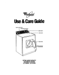
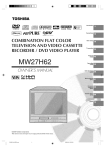
Hew te Use PrejectPre
WARNING
TM
Nozzle System
The quick-connect on the nozzle extension aliows you to
switch between three different ProjectProTM system nozzies.
ProjectProTM nozzlescan be changed whiie pressure washer
is running once spray gun trigger Iock is engaged. The
ProjectProTM nozzlesvary the pressure and spray pattern as
shown.
The high pressure stream of water that this
equipment produces can cut through skin and its
_
3.
.
iMPORTANT: Spray gun traps high water pressure, even
when engine is stopped and water is disconnected.
Placespray gun through hole on accessory tray on right
side of unit.
)ossibteamputation.
nderiying tissues, ieading to serious injury and
Spray gun traps high water pressure, even when
engine is stopped and water is disconnected,
which can cause injury.
High Pressure
• Keephigh pressurehoseconnectedto purnpand spray'gun
whilesystemis pressurized.
o ALWAYSpointspray'gun in safedirection,pressred button
and squeezespraygun trigger,to rebasehigh pressure,every'
time youstop engine.
Delicate
40° Yellow
2550 PSi
2.8 GPM
13
General
15° Orange
2800 PSi
2.7 GPM
Max
0° Red
3100 PSi
2.3 GPM
FoJJow
these in_rucflons to changeProjectPro
TM nozzJes:
1.
For maximum rinsing (higiler pressure and lower
flow), for stubborn or hard to reachsurface such as
second story surfaces, paint removal, oii stains, rust
removal or other stubborn substances (tar, gum,
grease, wax, etc.), select red max ProjectProTM
nozzle.
PulI back collar on quick-connect and pulI current
ProjectProTM nozzle off. Store ProjectProTM nozzlesin
holder provided on the accessorytray.
WARNING
The high pressure stream of water that this
underiying
serious skin
injury
and
quipment tissues,
producesieading
can cuttothrough
and
its
)ossible amputation.
* NEVERexchangeProjectPro
TM nozzles
without lockingthe
trigger lock on the spraygun.
_
o DONOTtwist ProjectPro
TM nozzles
whilespraying.
.
Select desired ProjectProTM nozzte:
o
Fordelicate rinse (iower pressure and higher flow),
for gentte cteaning of cars/trucks, boats, RV's, patio
furniture, iawn equipment, etc. select yellow
delicate ProjectProTM nozzle.
3.
Puff back on coflar, insert seiected ProjectProTM nozzle
and releasecollar. Tug on ProjectProTM nozzleto make
sure it is secureiy in piace.
4.
For most effectivecleaning, keep ProjectProTM nozzlefrom
8 to 24 inches away from cleaningsurface, if you get the
nozzietoo close, you may damagethe cleaningsurface.
5.
DONOTget closerthan 6 incheswhen cleaningtires.
Hew te Use the HydreFeam TM Launcher
The quick-connect on the nozzleextension aliows you to
attach the HydroFoamTM iauncher. Usethe HydroFoamTM
launcher to appiy HydroFoamTM wash or other project specific
cteaners to help break down stubborn dirt and grime on a
variety of surfaces.
Forgeneralrinsing (medium pressureand medium
flow), idealfor most aii purposecieaningsuch as
home siding, brick patios,wood decks, drivewaysand
sidewalks,garagefloors, etc. selectorangegeneral
ProjectProTM nozzle.
Followthese indmctions to attach the I.iydreFearn
TM launcher:
1.
PuiI back collar on quick-connect and pull current
ProjectProTM nozzle off. Store ProjectProTM nozzles in
hoider provided on the accessopJtray.
2.
Puff back on coliar, insert HyrdoFoamTM iauncher and
releasecoiiar. Tug on HyrdoFoamTM iauncher to make
sure it is securely in place.
iMPORTANT:Also see the HydroFoamTM launcher and wash
instruction sheet for important instructions and uses.
Cleaning and Applying Detergent
A, CAUTJO
Chemicalscan cause bodily injupj, and/or property damage.
UseONLYpressurewashersafedetergents/soaps.
Followall
_ manufacturers
EVERusecausticliquid
with pressurewasher.
instructions.
14
Toapplydetergent
followthesedope:
1. Review
ProjectPro
nozzleand HydroFoam
TM
TM
3.
launcheruse.
2.
Prepare HydroFoamTM wash according to instructions on
the bottb or prepare detergentsolution as required by job.
3.
Mace smaii fiiter end of detergent siphoning tube into
detergent container.
WARNING
Kickback from spray gun can cause you to fail.
o Operatepressurewasherfrom a stablesurface.
o Beextrerne[ycarefulif you mustusetbe pressurewasberfrom
a ladder,scaffolding,or anyotbersimilarlocation.
• Firmlygraspspraygun with both handswbenusing high
pressuresprayto avoidiniurywhenspraygun kicks back.
NOTE:Make sure the filter is fully submerged in detergent
while applying detergent.
NOTICE
Contact with the hot muffler can damage detergent
siphoning tube.
Wheninsertingthefilter intoa detergentsolutionbottb,routethe
tubesoasto keepitfrom inadvertently
contactingthehot rnuffler.
4.
Keepspray gun a safe distance from spray surface.
4.
Apply a high pressure spray to a smaiI area and then
check the surface for damage. If no damage, proceed to
step 5.
Start at top of area to be rinsed, working down with
same overlapping strokes used for cleaning.
Make sure HyrdoFoamTM Launcher is installed.
NOTE:Detergentcannot be appiied with the high pressure
nozzles (Yellow, Orange or Red).
Cteaning getergent $iphening Tehe
5.
If you used the detergent siphoning tube, you must flush it
with ciean water before stopping the engine.
6.
Make sure garden hose is connected to water inlet.
Checkthat high pressure hose is connected to spray gun
and pump. Turn on water.
1.
Start engine foilowing instructions How to Start Your
Pressure Washer.
.
3.
Ye--re
,(7u start the enqine.
_
Starting the engine without a!l the hoses connected and without
the water turned ON will damage tbe pump.
.
Darnageto equipment resulting from failure to follow this
instructionwill void warranty.
7.
Appiy HydroFoamTM wash to a dry surface, starting at
lower portion of area to be washed and work upward,
using iong, even, overlapping strokes.
Piacedetergent siphoning tube/filter in a bucket full of
clean water.
Remove high pressure nozzle from nozzle extension.
Seiect and instali btack detergent nozzle foliowing
instructions How to Use ProjeetProTMNozz/'eSystem.
Flush for 1-2 minutes.
5.
Shut off engine foliowing instructions How to Stop
Pressure Washerand turn off water supply.
6.
ALWAYS point spray gun in a safe direction, press red
button and squeezespray gun trigger to release retained
high water pressure.
iMPORTANT:Spray gun traps high water pressure, even
when engine is stopped and water is disconnected.
NOTE:To prevent water spotting on vehicles, work in a
shaded area and allow surfaces to cool before beginning.
8.
WARNING
The high pressure stream of water that this
equipment produces can cut through skin and its
underlying tissues, ieading to serious injupj and
_ossible amputation.
Spray gun traps high water pressure, even when
engine is stopped and water is disconnected,
which can cause injury.
Aliow HydroFoamTM wash to soak in between
3-5 minutes before washing and rinsing. Reappiy as
needed to prevent surface from drying. DO NOTaliow
HydroFoamTM wash to dry on (prevents streaking).
Forbest results, scrub the HydroFoamTM wash covered
surface to heip remove stubborn dirt, grime and stains. For
vehicles, use a soft car wash brush or mitt. For decking,
siding and concrete, use a brush appropriate for the type of
surface being cleaned.
o Keephigh pressurehoseconnectedto pumpand spraygun
whilesystemis pressurized.
• ALWAYSpointspraygun in safedirection,pressred button
and squeezespraygun trigger,to releasehigh pressure,every
time youstop engine.
IMPORTANT:You must flush the detergent siphoning system
after each use by placingthe fiiter into a bucket of clean water,
then run the pressure washer in low pressure for 1-2 minutes.
Automatic
Pressure Washer Rinsing
_,fterNydroFeam
TM wash is applied, seeer the eeffaee and rinse
it clean as fellows:
1.
Remove HyrdoFoamTM Launcher from nozzle extension.
2.
Select and install desired ProjectProTM nozzle,as
described in How to Use ProjeetProTMNozzleSystem.
Ceel gown System {Thermal Relief}
If you run the engine on your pressure washer for
3-5 minutes without pressing the trigger on the spray guls,
circulating water in the pump can reach temperatures above
125°F. The system engagesto cool the pump by discharging
the warm water onto the groend.
15
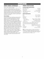
ENGINETECHNICALiNFORMATiON
PRODUCTSPECiFiCATiONS
This is a single cylinder, overhead valve (OHV), air cooled
engine, it is a iow emissions engine.
PressureWasher Specifications
In the State of California, Model Series 120000 engines are
certified by the California Air Resources Board to meet
emissions standards for 125 hours. Such certification does
not grant the purchaser, owner or operator of this engine any
additional warranties with respectto the performance or
operational life of this engine. The engine is warranted soidy
according to the product and emissions warranties stated
elsewhere in this manual.
Water Supply Temperature ..........
Shipping Weiglst.............................
Max Outbt Pressure .......................
Max Ftow Rate .............................
Chemicat Mix.........................
3,100 PSi
2.8 GPM
Use as directed
Not to exceed IO0°F
80 Ibs.
Engine Specifications
Bore ................................
2.672 in. (68mm)
Stroke ..............................
2.204 in. (56turn)
Displacement ........................
12.48 in. (206 cc)
SparkPlug
ResistorType: .............
Briggs & Stratton 491055S
Long Life Platinum: ..........
Briggs & Stratton 5066D
SetGap To: ......................
O.030inch(O.76mm)
Armature Air Gap: ...........
0.010o0.014in.(O.25=O.36mrn)
Valveclearancewith valvespringsinstalledand piston1/4in,
(6 rnrn)pasttop deadcenter(checkwhenengineis cold),
Intake ....................
0.004=0.006in.(O.lO=O.15
rnm)
Exhaust ..................
0.009o0.011in.(0.23=0.28mm)
Fue!Capacity...............................
1.6 Quarts
Oil Capacity ........................
20 Ounces(0.6 liter)
Pewer Ratings
The gross power rating for individuaI gas engine models is
labeled in accordance with SAE (Society of Automotive
Engineers)code J1940 (Small Engine Power & Torque
Rating Procedure), and rating performance has been
obtained and corrected in accordancewith SAEJ1995
(Revision 2002=05). Torque values are derived at 3060 RPM;
horsepower values are derived at 3600 RPM. Actuai gross
engine power wiii be lower and is affected by, among other
things, ambient operating conditions and engine-to-engine
variabiiity. Given both the wide array of products on which
engines are placed and the variety of environmental issues
appiicabb to operating the equipment, the gas engine wiii not
develop the rated gross power when used in a given piece of
power equipment (actual "on-site" or net power). This
difference is due to a variety of factors including, but not
limited to, accessories (air cteaner, exhaust, charging,
cooiing, carburetor, fuel pump, etc.), appiication iimitations,
ambient operating conditions (temperature, humidity,
altitude), and engine-to-engine vafiabiiity. Due to
manufacturing and capacity iimitations, Briggs & Stratton
may substitute an engine of higher rated power for this
Series engine.
NOTE:For practical operation, the engine load should not
exceed 85% of rated power. Engine power wiii decrease
3-1/2% for each 1,000 feet (300 meters) above sea level and
1% for each 10° F (5.6° C) above 77° F (25° C). It should
operatesatisfactorily at an angle up to 15°.
16
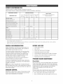
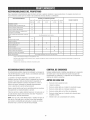
OWNER'SRESPONSiBiLiTIES
Follow the hourly or calendar intervals, whichever occurs first.
More frequent service is required when operating in adverse conditions noted below.
MABNTENANCE
SCHEBULE
OPERATINGINTERVALS
SERVICEDATES
MABNTENANCE
TASK
Before
Each Use
Hours or
Every 25
Yearly
1
Hours or
Evely 50
Yearly
Every 1O0
Hours or
FILL IN DATESAS YOU COMPLETE
REGULARSERVICE
Yearly
PRESSURE WASHER
X1
Chec_dcieanwater inlet screen
Check high pressure hose
X
Check detergent siphoning tube/filter
X
Check spray gun and assembly for leaks
X
Purge pump of air and contaminants
X
Prepare pump for storage below 32°F
ENGINE
Check oil bve[
Clean debris
See WiRter Storage,
X
X
Change engine oil
Service air cleaner
X
Service spark plug
X
Service spark attester
X_
Clean cooling system
Prepare for storage
If unit is to remain idb for longer than 30 days,
Clean if clogged. Replace if perforated or torn.
Change oil after the first (5) operating hours and every 50 hours or yearly thereafter. Changesooner when operating under dirty or dusty conditions.
Replace more often under dirty or dusty conditions,
GENERALRECOMJ ENDATION$
BEFUREEACHUSE
Reguiar maintenancewill improve the performance and
extend the life of the pressure washer. Seeany Sears or
other qualified service deaier for service.
1.
2.
Checkengine oil Ievei.
Cleandebris.
3.
Checkwater inlet screen for damage.
4.
Checkhigh pressure hose for leaks.
5.
Checkdetergent siphoning tube and filter for damage.
6.
Checkgun and nozzle extension assembly for leaks.
7.
Purge pump of air and contaminants.
The pressure washer warranty does not cover items that
have been subjected to operator abuse or negligence. To
receivefuli value from the warranty, the operator must
maintain pressure washer as instructed in this manual
including proper storage as detaiied in Storage.
Some adjustments wili need to be made periodicaliy to
properly maintain your pressure washer.
PRESSURE
WASHERMAINTENANCE
Ali service and adjustments should be made at bast once
each season. Foliow the requirements in the "Maintenance
Schedule" chart above.
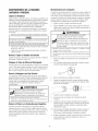
Clean Debris
Daily or before use, clean accumulated debris from pressure
washer. Keep linkage, spring and controls clean. Keep area
around and behind muffler free from any combustible debris.
Inspect cooiing air siots and openings on the pressure
washer. These openings must be kept clean and
unobstructed.
NOTE:Oncea year you should clean or replace the spark
ptug and repiace the air fiiter. A new spark piug and clean air
fiiter assure proper fuel-air mixture and hetp your engine run
better and iast longer.
EMi$$JUNCUNTRUL
Pressure washer parts should be kept ctean to reduce the
risk of overheating and ignition of accumulated debris.
, Use a damp cloth to wipe exterior surfaces clean.
Maintenance, replacementor repair of the emission control
devices and systems may be performed by any non-road
engine repair establishment or individual.
,
17
Use a soft bdstie brush to loosen caked on dirt, oil, etc.
WARNING
NOTICE
j Improper treatment of pressure washer can damage it and
_tsq_fe,
W_orten
_
....
DONOTinsert anyobjectsthroughcoolingslots.
° Usea vacuumcleanerto pick up loose dirt and debris.
The high pressure stream of water that this
equipment produces can cut through skin and its
)ossibie amputation.
nderiying tissues, ieading to serious injury and
Spray gun traps Ngh water pressure, even when
engine is stopped and water is disconnected,
which can cause injury.
• Keephigh pressurehoseconnectedto purnpand spraygun
whilesystemis pressurized.
o ALWAYSpointspraygemin safedirection,pressred button
and squeezespraygun trigger,to releasehigh pressure,every
time youstop engine.
_
Check and Cmean[n_et Screen
Examine garden hose inlet screen. Clean if it is clogged or
repiace if it is torn.
Check High Pressure Hese
High pressure hoses can develop leaks from wear, kinking,
or abuse, inspect hose before each use. Checkfor cuts,
leaks, abrasions, bulging of cover, or damage or movement
of coupiings. If any of these conditions exist, replace hose
immediately.
1
wA G
3.
Remove nozzlefrom end of nozzle extension.
4.
Use a smali paper clip to free any foreign material
clogging or restricting nozzle (A).
1
pressure stream
)ossibte
Dutation.
NEVERrepairhigh pressurehose.Replaceit.
ReplacementhoseratingMUSTexceedrnaxhnurnpressure
ratingof unit.
Remove nozzteextension from spray gun.
,
6.
Using a garden hose, remove additionai debris by back
flushing water through nozzteextension. Back flush
between 30 to 60 seconds.
Check Detergent $iphening Tube
Examine the filter on the detergent tube and clean if clogged.
The tube should fit tightly on the barbed fitting. Examinethe
tube for ieaks or tears. Replacethe filter or tube if either is
damaged.
jJ
_j
Check Gurt and Nozzle Extensien
Examine the hose connection to the spray gun and make
sure it is secure. Test the trigger by pressing the red button
and making sure the trigger "springs back" into place when
you releaseit. You should not be abie to press the trigger
without pressing the red button. Repiace spray gun
immediately if it faiis any of these tests.
Reconnect nozzle extension to spray gun.
Make sure garden hose is connected to water inlet.
Checkthat high pressure hose is connected to spray gun
and pump. Turn on water.
11. Test pressure washer by operating with each quick
connect nozzle.
A pulsing sensation feit while squeezingthe spray gun trigger
may be caused by excessive pump pressure. The principai
cause of excessive pump pressure is a nozztectogged or
restricted with foreign materiais, such as dirt, etc. To correct
the probiem, immediateiy clean the nozzle following these
instructions:
,
8.
9.
10. Start engine foiiowing instructions How to Start Your
Pressure Washe,<
Nezzle Maintenance
2.
........
Reinstaii nozzle into nozzle extension.
.
e-Ring Maintenance
Purchase an O-Ring Repair Kit at your Iocai Sears or by
cailing I-See-4-MY-NOME (469-4663) or ontine at
www.sears.com, it is not included with the pressure washer.
This kit includes repiacement o-rings, rubber washer and
water inlet fiiter. Refer to tile instruction sheet provided in the
kit to service your unit's o-rings=
Shut off engine and turn off water suppiy.
ALWAYSpoint spray gun in a safe direction, press red
button and squeeze spray gun trigger to releaseretained
high water pressure.
WARNING
The high pressure stream of water that this
_
underlying
quipment tissues,
producesieading
can cuttothrough
serious skin
injury
and
and
its
)ossibte amputation.
° NEVERrepairleakingconnectionswith sealantof anykind.
Replaceo-ring or seal.
18
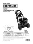
SAE30: 40°F and higher (5°C and higher) is good for aii
purpose use above 40%, use below 40°F will cause hard
starting.
Pump OiJMaintenance
DONOTattempt any oil maintenanceon this pump. This
model does not require any pump oii maintenance. The pump
is pre=iubricatedand sealed from the factory, requiring no
additional lubrication for the life of the pump.
10W-31_:O to IO0°F (=18to 38°C) is better for varying
temperature conditions. This viscosity improves coid weather
starting, but may increase oil consumption above 80%
(27%),
ENGINEMAINTENANCE
*Check oii ievei frequently at higher temperatures,
WARNING
Synthetic 5W-30:=20 to 120°F(=30to 40 °C) provides the
best protection at ati temperatures as well as improved
starting with iess oii consumption,
Unintentional sparking can result in fire or
_¢
5W-30: 40°F and be_;ow(5°C and below) is recommended for
winter use and works best in cold conditions,
electric shock.
CheckingOil Level
WHENADJUSTmNG
OR_IAKmNG
REPAmRS
TOYOURPRESSURE
WASHER
OiI level should be checked prior to each use or at least ever,/
5 hours of operation. Keep oii ievei maintained.
o Disconnectthe spark plugwire from the sparkplugand place
the wire whereit cannotcontactsparkplug.
WHENTESTINGFORENGmNE
SPARK
1.
Make sure pressure washer is on a ievei surface.
2.
Remove oii dipstick and wipe dipstick with ctean cioth.
Reptaceand tigilten dipstick. Removeand and check oil
level.
3.
Verify oiI is at "Full" mark on dipstick. Replace and
tighten dipstick.
* Useapprovedsparkplug tester.
. DONOTcheck
for sparkwith sparkplug removed.
Oil
Oil Recommendations
NOTE:Use a high quality detergent oiI classified "For Service
SF, SG, SH, SJ" or higiler. DO NOT use speciai additives.
1.
Choose a viscosity according to the table below:
4O C
86
68
?
30
20
50
i
lo
1.
Make sure pressure washer is on a level surface.
32
104F_
14
_
0
2.
Checkoii ievei as described in Checking Off Level
-10
3.
if needed,siowiy pour oil into oil fiii opening to the
"Full" mark on dipstick. DO NOT overfill.
4
-20
-22
-30
Overfiiiing with oil may cause the engine to not start, or
hard starting.
NOTE:Synthetic oii meeting iLSAC GF=2,APi certification
mark and APi service symboi with "SJ/CF ENERGY
CONSERVING"or higher, is an acceptabie oii at aii
temperatures. Use of synthetic oil does not alter required oil
change intervals,
DO NOTovertill.
If over the FULL mark on dipstick, drain oil to reduce oil level to
FULL rnark on dipstick.
4.
19
Replaceand tighten dipstick.
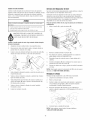
ChangingEngineOil
Service Air gleaner
Changeengine oii after the first 5 hours and every 50 hours
thereafter, if you are using your pressure washer under
extremely dirty or dusty conditions, or in extremely hot
weather, change oil more often.
Your engine wiii not run properly and may be damaged if you
run it with a dirty air cleaner.
CAUTION
Avoid prolonged or repeatedskin contact with used motor
oil.
Usedmotoroil hasbeenshownto causeskin cancerin certain
laboratoryanimals.
Thoroughlywashexposedareaswith soapandwater.
Service the air cleaner once every 25 hours of operation or
once each year, whichever comes first. Service more often if
operating under dirty or dusty conditions. Replacementsare
available at your local Searsservice center.
Te service the air cleaner,feiiew these steps:
1.
Loosen screw (A) and tilt cover (B) down.
2.
Carefully remove cartridge (C) assembly.
3.
To clean cartridge, gently tap pleated paper side on a fiat
surface.
4.
Reinstaii ciean or new cartridge assembly inside cover.
5.
Insert cover's tabs (O) into slots in bottom of base (E).
6.
Tilt cover up and tigilten screw securely to base.
KEEPOUT OFREACHOFCHLDREN. DON'T
POLLUTE.CONSERVERESOURCES.RETURN
USEDOIL TO COLLECTIONCENTERS.
Changeell while engineis still warm from running,as fellows:
1. Make sure unit is on a ievei surface.
2.
Disconnect the spark plug wire from the spark plug and
place the wire where it cannot contact spark plug.
3.
Cleanarea around oiI drain plug (A). The oiI drain plug is
located at base of engine, opposite carburetor.
NOTE:You can purchase new air filter elements by calling
l=800=4=_,IY=NO_,'IE
(469-4663).
4.
Remove oii drain piug and drain oil completely into a
suitable container.
5.
Reinstall oil drain plug and tigllten securely. Remove oil
fiii cap.
6.
Siowly pour oil (about 20 oz.) into oil fill opening (B) to
the point of overflowing (C) at oil fill cap. DO NOT
overfill.
7.
Reinstati oii fill cap. Finger tigilten cap securely.
8.
Wipe up any spilled oil.
Service Spark Plug
Service the spark piug every 100 hours of operation or
yearly, whichever occurs first.
1.
Cleanarea around spark plug.
2.
Removeand inspect spark plug.
3.
Repiacespark piug if eiectrodes are pitted, burned or
porcelain is cracked. Use the recommended replacement
plug. See Specificah;ons.
4.
Checkeiectrode gap with wire feeier gauge and set spark
plug gap to 0.030 inch (0.76 ram) if necessary.
5.
Instaii spark piug and tighten firmly.
NOTE:You can purchase a new spark plug by calling
l=808o4=MY=NOME
(469o4663).
2O
Spark Attester Service
AFTEREACHUSE
Your engine is not factory-equipped with a spark arrester. In
some areas, it is iliegai to operate an engine without a spark
arrester. Checkiocai iaws and regulations. A spark arrester is
avaiiablefrom your nearest Sears service center, if you need
to order a spark arrester, please call 1=800-4=MY=HOME
(469-4663).
Water should not remain in the unit for iong periods of time.
Sediments or minerats can deposit on pump parts and
"freeze" pump action. Follow these procedures after every
USe:
The spark arrester must be serviced every 50 hours to keep it
functioning as designed.
1.
Ftush detergent siphoning tube by piacing the fiiter into
a paii of cban water while running pressure wasiler in
low pressure mode. Fiush for one to two minutes.
2.
Shut off engine, turn off water suppiy, point gun in a
safe direction, press red button and squeezetrigger to
retieve trapped pressure, and let engine cool.
WARNING
;_
Contact with muffler
burns.
area can
WARNSNG
result in serious
The high pressure stream of water that this
equipment produces can cut through skin and its
underiying tissues, ieading to serious injury and
)ossible amputation.
Exhaustheat/gases can ignite combustibles,
structures or damage fue! tank causing a fire.
* DONOTtouch hot partsandAVOIDhot exhaustgases.
* Allowequipmentto cool beforetouching.
, Keepat least5 feet (152crn) of clearanceon all sidesof
pressurewasherincludingoverhead.
o Codeof FederalRegulation(CFR)Title 36 Parks,Forests,and
PublicPropertyrequireequipmentpoweredby an internal
combustionengineto havea sparkarrester,rnaintainedin
effectiveworkingorder,complyingto USDAForestservice
standard5100-1Cor laterrevision.Inthe Stateof Californiaa
sparkarresteris requiredundersection4442 of the California
Publicresourcescode.Otherstatesrnayhavesimilar laws.
Spray gun traps Iligh water pressure, even when
engine is stopped and water is disconnected,
which can cause injury.
o Keephigh pressurehoseconnectedto purnpand spraygun
whilesystemis pressurized.
• ALWAYSpointspraygun in safedirection,pressred button
and squeezespraygun trigger,to releasehigh pressure,every
tirneyoustop engine.
3.
Disconnect hose from spray gun and high pressure
outbt on pump. Drain water from hose, gun, and nozzte
extension. Use a rag to wipe off the hose.
4.
Empty pump of ali pumped iiquids by puiiing recoii
handb about 6 times. This should remove most liquid in
pump.
5.
Coii high pressure hose and properly hang it on hook
provided on accessorytray.
6.
Store unit in a dean, dry area.
7.
If storing for more than 30 days see Long Term Storage
on next page.
If the engine has been running, the muffler will be very hot.
Allow the muffier to cooi before servicing the spark arrester.
°
Removespark arrester screen for cteaningand inspection.
o Replace if screen is damaged.
Air Cooling System
Overtime debris may accumulate in cylinder cooiing fins and
cannot be observed without partial engine disassembly. For
this reason, we recommend you have an qualified Sears
service dealer clean the cooiing system per recommended
intervals (see MaintenanceSchedub). Equally important is to
keeptop of engine free from debris. See C/eanDebris.
WARNING
FueI and its vapors are extremely flammable and
expiosive.
death.
Fire or explosion can cause severe burns or
WHENSTORmNG
FUELOREQUIPiVlENT
WiTH FUELmNTANK
o Storeawayfrom furnaces,stoves,water heaters,clothes
dryers,or otherappliancesthat havepilot light or otherignition
sourcebecausetheycanignitefuelvapors.
21
WINTERSTORAGE
Change eiJ
While engine is still warm, drain oii from crankcase. Refill
with recommended grade. See ChangingEngine 0//'.
You must protect your unit from freezing temperatures.
Faik_reto do so will permanentlydamageyour pumpa_d
renderyour unit inoperable.
Freezedamageis not coveredunderwarranty.
eiJ CylinderBere
To protectthe unit frem freezing temperatures:
1. Foliow steps 1=5in the previous section After Each Use.
2.
Use pump saver, Model 6039, to treat pump. This
minimizes freeze damageand lubricates pistons and
seals.
3.
If pump saver is not available, connect a 3 ft. (1 m)
section of garden hose to water inlet adapter. Pour
RV-antifreeze (antifreezewithout atcohol) into hose. Pull
recoil handle twice. Disconnect 3 ft. (1 m) hose.
4.
°
Removespark plug and pour about 1/2 ounce (15 rot) of
clean engine oii into the cyiinder.
o
Instali spark plug and pull starter handle slowly to
distribute oil.
Preteet Pump
To protect the pump from damage caused by mineral
deposits or freezing, use PumpSaver, Model 6039, to treat
pump. This prevents freeze damageand lubricates pistons
and seaIs.
NOTE:PumpSaver is avaiiabie as an optionat accessory, it is
not included with the pressure washer. Contact your local
Searsservice center to purchase PumpSaver.
Store unit in a clean, dry area.
You must protect your unit from freezing temperatures.
LONGTERM STORAGE
Failure to do so will permanently damage your purnp and
render your unit inoperable
Freezedamage is not covered under warranty.
If you do not plan to use the pressure washer for more than
30 days, you must prepare the engine and pump for long
term storage.
It is important to prevent gum deposits from forming in
essential fuel system parts such as the carburetor, fuel filter,
fuel hose or tank during storage. Also, experience indicates
that abohoPbtended fuels (called gasohol, ethanol or
methanol) can attract moisture, which leads to separation
and formation of acids during storage. Acidic gas can
damagethe fuel system of an engine while in storage.
To use PumpSaver, make sure the pressure washer is turned
off and disconnected from supply water. Readand foliow aii
instructions and warnings given on the PumpSavercontainer.
1.
DO NOTstore fuet from one season to another unless it
has been treated as described in Protect Fue/System.
Pretect Fuel System
2.
Repiacefuel container if it starts to rust. Rust and/or dirt
in fuet can cause probiems if it's used with this unit.
Feel Preserver:
3.
Cover unit with a suitable protective cover that does not
retain moisture.
Other eterage Tips
FilIthe fue! tank with fresh fuei aliowing at bast 1.5" of tank
space for fuel expansion as shown on page 8, when using a
fue! preserver cartridge with the fresh start fuei cap. if only
partialiy fiiied, air in the tank wiii promote fuei deterioration
during storage. Engine and fuel can be stored up to 6 months
with fuel preserver.
,
Check level of fuel preserver cartridge. Fuelpreserver is
dark in color.
o
If cartridge is almost empty or empty, repiacewith a new
fuel preservercartridge following the instructions in Fresh
Sta,q
_TM
Fud @p on page 9.
WARNING
Storagecovers can be flammable.
o DONOTplacea storagecoverovera hot pressurewasher
• Letequipmet_tcoolfor a sufficienttime beforeplacingthe
coveron the equipment
4.
If fuei preserver is not used, remove ali fuel from tank and
run engine until it stops from lack of fuel.
22
Store unit in a clean and dry area.
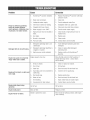
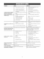
Pumphas followingproblems:
failure to producepressure,
erratic pressure, chattering, loss
of pressure, low water volume,
Detergent fails to mix with spray.
Engine runs good at noqoad bat
"bogs" when load is added.
Engine will not start; or starts and
runs rough.
1.
Replace HydroFoamTM launcher with high
pressure nozzb.
2.
Water inlet is blocked.
2.
Clearinlet.
3.
Inadequate water suppiy.
3.
Provide adequatewater flow.
4.
Inlet hose is kinked or baking.
4.
Straighten inlet hose, patch ieak.
5.
Clogged inbt hose strainer.
5.
Checkand clean inlet hose strainer.
6.
Water suppiy is over IO0°F.
6.
Provide cooier water suppiy.
7.
High pressure hose is blocked or
leaks.
7.
Clearblocks in high pressure hose or
repiace hose.
8.
Gun leaks.
8.
Repiacegun.
9.
Nozzleis obstructed.
9.
Cleannozzle.
10. Pump is faulty.
10. Contact Sears service facility
1.
Detergent siphoning tube is not
submerged.
1.
Insert detergent siphoning tube into
detergent.
2.
Detergent siphoning tube/fiiter is
clogged or cracked.
2.
Cleanor replace filter/detergent
siphoning tube.
3.
High pressure nozzle installed.
3.
Repiace nozzlewith HydroFoamTM
launcher.
Engine speed is too slow.
Move throttb control to FASTposition. If
engine still "bogs down", contact Sears
service facility.
1.
Dirty air cleaner.
1.
Cleanor replace air cleaner.
2.
Out of fuel.
2.
Fill fuet tank.
3.
Stale fuel.
3.
Drain fue! tank; fill with fresh fuel.
4.
Spark ptug wire not connected to
spark plug.
4.
Connectwire to spark plug.
5.
Bad spark plug.
5.
Replacespark plug.
6.
Water in fuel.
6.
Drain fuel tank; fill with fresh fuel.
7.
Overchoking.
7.
Open choke fuiiy and crank engine.
8.
Excessively rich fuel mixture.
8.
Contact Sears service facility.
Engine shuts down daring
operation.
Out of fuel.
Fill fuel tank.
Engine lacks power.
Dirty air filter.
Replaceair filter.
Choke is opened too soon.
Move choke to halfway position until engine
runs smoothly.
Engine "bunts" or falters.
23
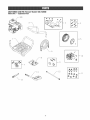
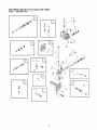
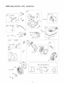
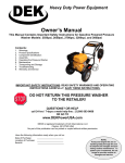
CRAFTSMAN3100 PSi Pressure Washer 580,752080
Main Unit _ ExpJodedView
900
--3
--iO
@@@@
@@@@
24
--11
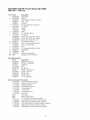
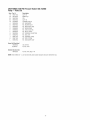
CRAFTSMAN3188 PSi Pressure Washer 58&752888
Main Unit _ Parts List
item
I
2
3
4
5
6
7
8
9
10
11
12
13
14
900
Part #
202974GS
B201499GS
202975GS
195964GS
30809GS
192131GS
202978GS
200517GS
192050GS
202634GS
192553GS
201758GS
201580RGS
201580XGS
201580AAGS
B2203GS
198347GS
194298GS
23139DGS
192134GS
200595GS
199990GS
198423GS
NSP
items Not illustrated
Part #
203794GS
199462GS
87815GS
201314GS
AB3061BGS
282432
202704GS
202706GS
200658GS
194256GS
Description
ASSY, Base
HANDLE
ASSY, Biilboard w/Decals & Clips
Ctips, Tree
Grommet
KiT, Pump Mounting Hardware
KIT, Wheel
Hubcap
E-Ring
HOSE
KiT, Vibration Mount
KIT, Nozzte
Nozzie, QC, Project Pro, Yeiiow
Nozzle, QC, Project Pro, Orange
Nozzie, QC, Project Pro, Red
KiT, HandleFastening
ASSY, Pump (see pages 26-27)
Vaive, Thermal Refief
Key
KiT, Engine Mounting Hardware
EXTENSION
GUN
ASSY, Foaming Nozzie
ENGINE(121012-0123°B1)
Description
MANUAL, Operator's
BOTTLE,Concentrate
GOGGLES
AXLE
OIL BOTTLE
KNOB,Throttle Back
DECAL,Cover Air
DECAL,Eng
DECAL,Recoii
KIT, Tag Warning
OptionalAccessoriesNetIllustrated
7175187GS Garden Hose Quick Connect
7175197GS Accessory Quick Connect
7175124GS Rotating Brush Kit
7175122GS 30' Repiacement Hose
7175116GS 0 Ring Repair Kit
7175129GS Turbo Nozzle
7175121GS 25' Extension Hose
7174402GS Hose Reel
6039
Pump Saver
6092
WASH, HydroFoamTM
6135
KiT, HydroFoamTM Launcher & Wash
7174300GS House Wash Concentrate (makes 4 gations)
7174301GS Deck Wash Concentrate (makes 2 gaiions)
7174302GS Vehicie/BoatWash Concentrate (makes 4 gallons)
7174303GS DegreaserConcentrate (makes4 gations)
7174307GS MoWMildew Concentrate (makes 2 gallons)
25
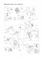
CRAFTSMAN3100 PSi Pressure Washer 580_752080
Pump -- Expi0ded View
B
?
e
@
o
o
tj
2G
CRAFTSMAN3188 PSi Pressure Washer 58&752888
Pump _ Parts List
item
19
28
45
62
76
A
B
C
D
E
F
G
H
J
K
L
Part #
190571GS
198102GS
190578GS
190581GS
19429BGS
190594GS
19067BGS
190669GS
193BBBGS
193806GS
190592GS
190593GS
193807GS
189971GS
193971GS
193972GS
Description
CAP,Oil
MANIFOLD
PiN
CAP,!/8
THERMALRELIEF
KIT,UNLOADER
KIT,WATERINLET
KIT,BREATHER
TUBE
KIT,HEADBRASS
KIT,CHECKVALVES
KIT,INLETCHECK
KIT,CHEMICAL
INJECTION
KIT,SEALSET
KIT,CHEMICAL
HOSE
KIT,PIPEFITTING
KIT,UNLOADER
SEAT
items Not HRustrated
190585GS
B2384GS
OIL BOTTLE
FILTER,Inlet
O#tionaJ Accessnfies
186452GS
FILTER,brier,Bag of 10
NOTE:item letters A o L are service kits and include all parts shown within the box.
27
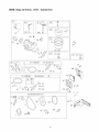
ENGINE,Briggs and $tratton, 121012 - ExplodedView
_40
1022
@
619 _@
3s_ _38
0
1034
36q_
830
868
_o@
_"
914A _@
337_
14B d@
10
9!4 d@
718
12
15
415 @
22d_
@
15A
746
742
32A
21_o
28
ENGINE, Briggs and Stratten,
633 (@
127
121012 - Exploded View
633A @
692
163
186
%
t37
108
365
276
95 _
276 _o=}
276
51
425_
968
977 CARBURET633A
@ORGASKET
SET5_633 @163_
!21 CARBURET
OROVERHAUL
445
KIT
161
633A @
971
51_
633 @
276
163
358 ENGINEGASKETSET
3_
2o
51
12
993 _o_
663
1022
281
883
163
sss_
29
ENGINE, Briggs and $tratten,
121012 - Exploded View
209A
562
427 ®
773
271 __
209
334
668
188 1'
621
300
836 ?
613 _'
356 _<_1_%
832
883 _
836A
958
4566899_45
65
5s L_j
I211
3
55
23
1095 VALVEGASKETSET
10701005_
993 _86851
102
455_
332 @
3O
ENGJNE_Briggs and $tratton,
Item
1
2
3
5
7
11
12
13
15
15A
16
18
20
21
22
23
24
25
26
27
28
29
30
32
32A
33
34
35
36
40
45
46
51
55
58
60
65
95
97
98
104
108
109
117
118
121
122
125
127
130
133
134
137
146
155
161
163
186
187
187A
188
190
192
209
209A
219
226
222
227
238
271
276
281
300
Part #
699510
399269
299819S
699486
698210
692600
699485
699482
691686
691682
699445
699804
692550
281658S
699478
699488
222698S
791097
791326
791969
791324
691866
499423
690124
692562
691664
695759
499642
499641
691304
691304
692194
690977
693404
692555
691422
693389
691915
699228
691636
690024
398185
691242
692567
690023
690048
498976
792006
693749
698474
691739
691181
398187
398188
693981
690979
698214
699207
696024
692317
791766
791867
699479
699220
694543
691278
692571
693578
691724
793108
692573
691300
695743
271716
793122
693593
121012 - Parts List
Description
Cylinder Assembly
Kit-Bushing/Seal (Magneto Side)
£ Oil Seal (Magneto Side)
Bead-Cylinder
£ 1 Gasket-Cylinder Head
Tube-Breather
£ Gasket-Crankcase
Screw (Cylinder Head)
Plug-Oil Drain
Plug-Oil Drain
Crankshaft
Cover-Crankcase
£ Seal-Oil (PTO Side)
Cap-Oil Fill
Screw (Crankcase Cover)
Flywheel
Key-Flywheel
Piston Assembly (Standard)
Piston Assembly (.020" Oversize)
Ring Set (Standard)
Ring Set (.020" Oversize
Lock-Piston Pin
Pin-Piston
Rod-Connecting
Dipper-Connecting Rod
Screw (Connecting Rod
Screw (Connecting Rod
Valve-Exhaust
Valve-Intake
Spring-Valve (Intake)
Spring-Valve (Exhaust)
Retainer-Valve
Tappet-Valve
Camshaft
¥ £ $ t Gasket-intake (2 Required)
Housing-Rewind Starter
Rope-Starter
Starter Rope Grip
Screw (Rewind Starter)
Screw (Throttle Valve)
Throttle Shaft
Kit-Idle Speed
Pin-Float Hinge
Valve-Choke
Shaft-Choke
Jet-Main (Standard)
Jet-Main (High Altitude)
Kit-Carburetor Overhaul
Spacer-Carburetor
Carburetor
¥ Plug-Welch
Valve-Throttle
Float-Carburetor
¥ Valve-Float Needle
¥ $ Gasket-Float Bowl
Key-Timing
Plate-Cylinder Head
Base-Air Cleaner
¥ £ 1:Gasket-Air Cleaner
Connector-Hose
Line-Fuel (Cut to Required Length)
Line-Fuel (Molded)
Screw (Control Bracket)
Screw (Fuel Tank)
Bali-Rocker Arm
Spring-Governor
Spring-Governor
Gear-Governor
Washer (Governor Gear)
Bracket-Control
Lever-Governor Control
Cap-Valve
Lever-Control
¥ Washer-Sealing
Panel-Control
Muffler
Item
304
3O5
306
307
332
333
334
337
356
358
365
415
425
427
445
455
456
459
504
505
552
562
597
601
608
613
615
616
619
621
632
633
633A
635
663
668
689
692
718
741
742
746
773
830
832
836
836A
851
868
883
914
914A
914B
957
958
968
971
972
975
977
993
1005
1022
1023
1026
1029
1034
1095
1070
1210
1211
Part #
699598
699480
693610
699483
792723
695711
699477
491055S
692390
791797
699484
693463
699208
694255
491588S
692591
692299
281505S
694254
691251
692346
691112
691696
791850
699394
791972
692576
692547
699480
692310
693408
693867
691321
692076
699206
694257
691855
690572
690959
695087
692564
790278
694258
694544
693583
699632
699203
493880S
692044
691893
699480
692557
697551
792647
698180
692584
690370
694260
493640
697001
694088
692592
691890
499924
790287
691230
691343
791798
699201
498144
498144
£
¥
Included
Included
Included
Included
t
t
31
Bes_riptUon
Housing-Blower
Screw (Blower Housing)
Shield-Cylinder
Screw (Cylinder Shield)
Nut (Flywheel)
Armature-Magneto
Screw (Magneto Armature)
Plug-Spark
Stop Wire
Gasket Set-Engine
Screw (Carburetor)
Plug
Screw (Air CleanerCover)
Nut (Control Bracket)
Filter-A/C Cartridge
Cup-Flywheel
Plate-Pawl Friction
PawI-Ratchet
Washer Set-Friction
Nut (Governer Control Lever)
Bushing-Governor Crank
Bolt (Governor Control Lever)
Screw (Pawl Friction Plate)
Clamp-Hose
Starter-Rewind
Screw (Muffler)
Retainer-Governor Shaft
Crank-Governor
Screw (Cylinder Head Plate)
Switch-Stop
Spring/Link-Mechanical Governor
¥ $ Seal-Choke/Throttle Shaft
¥ $ Seal-Choke/Throttle Shaft
Boot-Spark Plug
Screw (Control Panel)
Spacer
Spring-Friction
Spring-Detent
Pin-Locating
Gear-Timing
Ring-Retaining
Gear-idler
Retainer
Stud (Rocker Arm)
Guard-Muffler
Screw (Muffler Guard)
Screw (Muffler Guard)
Terminal-Spark Plug
£ 1 Seal-Valve
£ Gasket-Exhaust
Screw (Rocker Cover) (Bottom)
Screw (Rocker Cover) (Top)
Screw (Rocker Cover) (Sides)
Cap-Fuel Tank
Valve-Fuel Shut Off
Cover-Air Cleaner
Screw (Air CleanerBase)
Tank-Fuel
Bowl-Float
Gasket Set-Carburetor
£ 1- Gasket-Cylinder Head Plate
Fan-Flywheel
£ 1- Gasket-Rocker Cover
Cover-Rocker
Rod-Push
Rocker Arm
Guide-Push Rod
Gasket Set-Valve
Screw (Flywheel)
Pulley/Spring Assembly (Pulley)
Pulley/Spring Assembly (Spring)
in
in
in
in
Engine Gasket Set, Item 358
Carburetor Overhaul Kit, Item 121
Carburetor Gasket Set, Item 977
Valve Gasket Set, Item 1095
Sears, Roebuck and Co., &S,A, (Sears), the California Air Resources Board ICARB) and
the United States Environmental Protection Agency {U,S,EPA)
Emissions CentromSystem Warranty Statement
ISwneCs Defect Warranty Rights and 8hmigations)
The California Air Resources Board (CARB), U.S. EPA and Sears are
pleased to explain the Emissions Centre[ System Warranty on your
srnaI[ offroad engine (SORE).hr California, new small ofroad
engines rnodel year 2006 and later must be designed, built and
equipped to meet the State's stringent anti-smog standards.
Elsewherein the United States, new non-road,spark-ignition engines
certified for mode[year 1997 and later must meet similar standardsset
forth bythe U.S. EPA.Sears must warrant the emissions control
system on your engine for the periodsof time listed below, provided
there has beenno abuse, neglector improper maintenanceof your
small of-road engine.
Your emissions centre[ system includes parts such as tire
carburetor, air cleaner, ignition system, fuel line, muffler and
catalytic converter. Also included rnay be connectors and other
emissions related assemblies.
*
*
*
,
,
b.
*
°
.
c
,
,
d.
*
,
Where a warrantable condition exists, Sears will repair your small
off-road engine at no cost to you including diagnosis, parts and
labor.
Carburetor and hrternal parts
Fuel Pump
Fuel line, fuel [hrefittings, clamps
Fue[tank, cap and tether
Carbon canister
Air Induction System
Air cbaner
Intake rnanl%d
Purge and vent line
Ignition System
Spark plug(s)
Magneto ignition system
Catalyst System
Catalytic converter
Exhaust manifold
, Air iniection system, Pulse valve
e. Miscellaneous Items
Sears, Roebuck and Co. Emissions Control Befects Warranty
Covera_je
Small of-road engines are warranted relative to ernissions control
parts defects for a period of two years, subiect to provisions set
forth below. If any covered part on your engine is defective,the part
will be repaired or replaced by Sears.
Owner's Warranty Responsibilities
As tire small of-road engine owner, you are responsible for tire
performance of the required rnaintenancelisted in your Operating
and Maintenance Instructions. Sears recommends that you retain all
your receipts covering maintenance on your small off-road engine
but Sears cannot deny warranty solely for the lack of receipts or for
your failure to ensurethe performance of all scheduled rnaintenance.
As the small off-road engine owner, you should however be aware
that Sears may deny you warranty coverage if your small of-road
engine or a part has failed due to abuse, neglect, improper
rnaintenanceor unapproved modifications.
You are responsible for presenting your small off-road engine to an
Authorized Sears Service Dealeras soon as a problem exbts.
The undisputed warranty repairs should be completed hr a
reasonable amount of time, not to exceed30 days.
If you have any questions regarding your warranty rights and
responsibilities, you should contact a Sears Service Representative
at 1-800-469-4663.
,
2.
3.
Vacuum, temperature, position, tirne sensitive valves and
switches
o Connectors and assernNbs
Length of Coverage
Sears warrants to the initial owner and eachsubsequent
purchaser that the Warranted Parts shahbe free from defects in
materials and workrnanship which caused the failure of the
Warranted Parts for a period of two years from the date tire
engine is deliveredto a retail purchaser.
No Charge
Repair or replacement of airy Warranted Part will be performed
at no charge to the owner, hrcluding diagnostic labor which
leads to the determhration that a Warranted Part is defective if
the diagnostic work ls performed at an Authorized Sears
Service Dealer.
4.
CJaims and Coverage Exclusions
Warranty claims shah be filed hr accordance with the provls_ons
of the Sears Engine Warranty Policy. Warranty coverage shall
be excluded for failures ofWarranted Parts which are not
original Sears parts or becauseof abuse, neglect or improper
rnaintenanceas set forth in the Sears Engine Warranty Policy.
Sears is not liable to cover failures of Warranted Parts caused
by the use of add-on, non-original, or rnodified parts.
5. _daintenanse
Any Warranted Part which is not schedubd for rephcement as
required rnaintenanceor which is scheduled only for regular
inspection to the effect of "repair or replaceas necessary"shall
be warranted asto defects for tire warranty period. Any
Warranted Part which is scheduledfor replacementas required
rnaintenanceshall be warranted as to defects only for the period
of time up to tire first scheduled replacernentfor that part. Any
replacement part that is equivalent in performance and
durabilityrnay be used in the perforrnanceof any maintenanceor
repairs. The owner is responsible for the performance of all
required rnaintenance as defined in the Sears Operating and
Maintenance Instructions.
6. Consequential Coverage
Coverage hereunder shall extend to the failure of any engine
components caused by tire failure of any Warranted Part still
under warranty.
The emissions warranty is a defects warranty. Defects are iudged
on normal engine performance. The warranty is not related to an inuse emissions test.
Sears, Ree#eek and Cn, Emissinns Cnntrni #efents Warranty
Prnvisinns
The following are specific provisions rebtive to your Emissions
Control Defects Warranty Coverage.It is in addition to the Sears
engine warranty for non-regulated engines found in the Operating and
MahrtenanceInstructions.
1. Warranted Parts
Coverageunder this warranty extends only to the parts listed
below (the emissions control systems parts) to the extent these
parts were present on the engine purchased.
a. Fuel Meterhrg System
* Cold start enrichment system
In the USA and Canada,a 24-hour hotlhre, 1-800-469-4663, has a rnenu of pre-recorded rnessagesoffering you product maintenance
hrforrnatlon.
32
EmJ_ion information
Certain engines wiii be certified to meet the United States
Environmental Protection Agency (USEPA)Phase 2 emission
standards. For phase 2 certified engines, the Emissions
Compiiance Period referred to on the Emissions Compliance
label indicates the number of operating hours for which the
engine has been shown to meet Federalemission
requirements.
Enginesthat are certified to meet the California Air Resources
Board (CARB) Tier 2 Emission Standards must display
information regarding the Emissions Durabiiity Period and Air
Index. The engine manufacturer makesthis information
avaiiabteto the consumer on emission iabeis, The engine
emission iabet wili indicate certification information,
For engines iess than 225 cc displacement:
CategoryC = 125 hours
Category B = 250 hours
CategoryA = 500 hours.
The Emissions Durability Period describes the number of
hours of actual running time for which the engine is certified
to be emissions compliant, assuming proper maintenancein
accordancewith the Operating & Maintenance Instructions.
The following categories are used:
For engines of 225 cc or more displacement:
CategoryC = 250 hours
Category B = 500 hours
CategoryA = 1000 hours.
Moderate: Engine is certified to be emission compliant for
125 hours of actual engine running time.
Intermediate: Engine is certified to be emission compliant
for 250 hours of actual engine running time.
Extended: Engine is certified to be emission compiiant for
500 hours of actual engine running time.
Forexample, a typical walk-behind lawn mower is used 20 to
25 hours per year. Therefore, the Emissions Durability
Period of an engine with an intermediate rating would
equateto 10 to 12 years.
33
GARANTIA
..........................................
REGLAS
DESEGURIDAD
............................
CARACTERiSTICAS
YCONTROLES
.......................
MONTAJE
........................................
OPERAC!ON
.......................................
ESPECIFICAC!ONE8
...................................
34
34-37
38
39-42
43-47
48
IVlANTEI',IIIVlIENTO
..................................
49-53
ALMACENAMIENTO ...................................
54
REPARAC!ONDE DA_@SREPUESTOS ....................
55
NOTA8 ...........................................
56-57
GARANTIADEL CONTROLDE EMBIONES ...............
COMOORDENARPARTES ...............
58-59
PAGINAPOSTERIOR
Garant_a ¢empieta de un a_e de _a_impiadera a presi6n Craftsman
Si la limpiadora a presiOn falls debido a defectos de materiales o rnalsode obra en el plazo de un aiio a partir de la fecha de compra,
devu61valaa cualquier almac@ Sears_punto de vents de Craftsman o centro de reparaci@ y repuestos de Sears de los Estados Unidos o
Canad_ pars su reparaci@ gratuita o en caso de que 6sta no sea posibb, pars su sustituci6n.
El periodo de garantia se reducir_ a 99 dias des@ la fecha de cornpra si la limpiadora a presiOn se utiliza en alg8n rnornento con fines
cornerciales o de alquibr.
Esta garantia le otorga deterrninados derechos legabs yes posible que tenga otros derechos que pueden variar de un pais o estado a otro.
Sears, Reebuek and Co,, Dept, 817 WA, Heffman Estates, JL 6elTg
Sears Canada Jnc,, Terente, entarie, Canada MSB 2B8
Este es emsimbob de abrta de seguridad, Esusado pars indieaHe situaeiones con peHgrospoten¢iabs de bsion pars e_
personal Siga masinstrueciones de todos bs mensajes de seguridad que aparecen despues de este simbob pars evitar posihbs
Jssione$
o lnuet'te,
I_I'
.... / Leaestemanualminu¢iosamentey ¢onezcaa rondolas
iL.:-_-.
I partesy eJf..¢b.amb.,o de s. m_q.l.a Hmpladoraa
presi6n.Cenezcasus apJieaeienes,sus Jimitaeienes
y Jes
peligrosinvoluerados,
Descarga El@trica
El sfrnbolo de abrta de seguridad (,_0 es usado con una palabra
(PELIGRO ADVERTEt,
ICIA PRECAUC!ON)_
u_smensajepor escrito o
una ilustraciOn, para alertado acerca de cualquier situaciOnde
peligro que pueda existir. PELt6RO indica un riesgo el cual, si no se
evita causafd la muerte o una heridagrave. ADVERTENCIAindica un
riesgo el cual si no se evita puedecausar la muerte o una herida
grave. PRECAUCm6N
indica un riesgo, el cual_si no se evita_puede
causar heridas rnelsoreso moderadas. AVISOindica una situaci@
Caer
SuperficiesResbalosas
Inyecci6nLfquida
que podria resultar en el da[io de! equipo. Siga los mensajesde
seguridad para evitar o reducir los riesgos de hefidas e inclusive la
muerte.
Partes en Movimiento
Fuego
34
Objetos Voladores
Explosi6n
Superficie6aliente
ManualdelOperario
Contragolpe
ADVEBTENCIA
ADVERTENCiA
EJescape deJ motor de este producto centJene eJementos
quJmJ¢os re¢onocJdos en eJ Estado de CaJJfornJa
La gasolinay susvaporessonextrernadamente
pot producJr ¢;_ncer, defectos de nacJmJento
inflamables
y exp!osivos.
u otros dafios de tJpo reprodu¢flvo,
severas
la muerte.
E[ fuego eoinclusive
una explosi6n
pueden causar quernaduras
PELJGRO
CUANDO ANADA cor_IBUSTmBLE 0
Su 6ontenidoes NOClVO0 FATALENCASODESER
/_
Apague el limpiadora a presi(_n(posici6n OFF)y d_jelo enfriar al menos
por 2 minutos antes de remover la tapa de la combustible. Afloje la
tapa lentamente para dejar que la presi6n salga del tanque.
INGERIDO.
Eviteinternarnente.
el contacto con
losrespirar
ojos la lapie!
o la o
ropa. No tomar
Evite
niebla
el vapor. La
exposici6nexcesiva
de los
oios o
la
piel
)uede causar irritaciOn. Mantenga el estabilizador
o Llene o vac[e el depOsito de combustible a la intemperie.
fuera
del aIcance de los nifios.
El estabilizador de combustible es un qufmico peligroso.**
,
La tapa de combustible FreshStartTM est_ diseflada para sostener un
cartucho el cual contiene el estabilizador de combustible.
,
EI',JCASO DE SERINGERIDO,Ilame un medico inmediatamente. No
induzca el v6mito. En caso de inhalaciOnsalir al aire libre. En caso de
contacto con los ojos o con la piel, lavar abundantemente con agua
durante 15 minutos.
,
NO Ilene demasiado el tanque. Permita al menos espacio para la
expansi6n del combustible.
,
Si se ha derramado combustible, espere a que se evapore antes de
arrancar el motor.
,
Mantenga la gasolina alejada de chispas, llamas abiertas, pilotos, calor
y otras fuentes de ignici6n.
,
NO encienda un cigarrillo o fume.
CUANDO PONGA EN FUNCIONA{VIIENTO EL EQUBPO
o Compruebe que la bujfa el silenciador, el tap6n del dep6sito de
combustible y el filtro de aire est_n instalados.
o Almacene los cartuchos sin abrir en un _rea fresca, seca y bien
ventilada. Mantenga el cartucho abierto en latapa de combustible, y la
tapa de combustible cerrada en el tanque de combustible cuando no
est_ en uso.
o NO arranque el motor sin la buj[a instalada.
CUANDO OPEBEELEQUmPO
o En caso de la emergencia, contacte a un mSdico inmediatamente y llama
1-800-424-9300 para la informaci6n material de la seguridad.
NO incline el motor o el equipo, de tal manera que la gasolina se pueda
derramar.
**El estabillzadorde combustiblecontiene2,6-di-tert-butilfenol(128-39-2)y
destlladodepetr61eoallf_tlco(64742-47-8).
,
o Transporte o repare el equipo con el tanque de combustible vac[o, o
con la v_ilvulapara apagar el combustible, apagada (posici6n OFF).
AI motor funcionar,se producemon6xidode carbono,
un gasinodoroy venenoso.
,
Almacene alejado de calderas, estufas, calentadores de agua, secadoras
de ropa u otros aparatos electrodom6sticos que posean pilotos u otras
fuentes de igniciOn, porque ellos puedenencender los vapores de la
combustible.
de cabeza,n_useas,
ataques
fatiga, rnareos,
desmayosvOrnitos,
o incIuso
confusion,
la rnuerte.
perjudicialessi
quirnicas o los detergentes
inhalados
o
pueden
ingeridos,causando
Desconecte el cable de la buj[a.
CUANDO ALMACE_iE
0 GUARDE ELEQUmPOCON CO_vIBUSTmBLE
EN ELTANQUE
Respirarmon6xidode carbonopuedeprovocardolor
ser
NO rocie I[quidos inflamables.
CUANDO TRANSPORTE0 REPAREELEQUIPO
ABVERTENCiA
Algunas sustancias
VACiEELDEP6SmTO
la
is_lJsea severa, desrnaya!sdo o para elwe!serlar.
,
,
Opere el limpiadora a presi6n SOLAMENTEal aire libre.
AsegOresede que los gases de escape no puedan entrar por ventanas,
puertas, tomas de aire de ventilaci6n u otras aberturas en un espacio
cerrado en el que puedan acumularse.
,
I'_10arranque ni deje funcionar el motor en interiores ni en zonas
cerradas, aunque haya ventanas y puertas abiertas.
,
Utilice un respirador o m_iscarasiempre que exista la posibilidad de
inhalar vapores.
,
Lea todas las instrucciones de la m_scara para asegurarse de que le
brindar_ la protecci6n necesaria contra la inhalaciOn de vapores
ADVEBTENCiA
_¢
,
nocivos,
35
E! contacto con los cables eIactricos
[esgo de e]ectrocuci6n.
electrocuci6n y quernaduras.
puedeprovocar
NUNCA rocie cerca de una fuente de energia el6ctrica.
ADVERTENCJA
ADVERTENCJA
El retroceso (repliegue r@ido) del cable del arrancador
El cborro de agua a alta presi6n que este equipo
puede producir
produce
bsiones
El retroceso impedir_ que el
usuario sueIte e! cable a tiernpo y tirarA de su mano y
brazo Isacia el motor.
)odrias dar lugar a la amputaci@ de un rniernbro.
ubcut_neos, provocando lesiones de gravedad que
La pistola rociadora contiene agua a aIta presi6n incluso
_
Corno resuItado, pod!ian producirse
contusiones
fracturas
o esguinces.
cots e! motor parado y el agua desconectada, que puede
causar la Iserida.
NUNCAtire del cable del arrancador sin elirninar previamente la presi6n
de la pistola rociadora.
Cuando arranque el motor, tire lentamente del cable hasta sentir una
resistencia y, a continuaciOn, tire r_pidamente de 81para evitar su
retroceso.
o NO permita en ningSn momento que NINOS operen la m_quina
limpiadora a presiOn.
o NUNOA repare la manguera de alta presi6n. Remplacela.
o Despu6s de cada intento de arranque, cuando el motor no consiga
arrancar, apunte con la pistola rociadora hacia una direcci6n segura,
pulse el bot6n rojo y apriete el gatillo para descargar la presi6n.
o Sujete firmemente la pistola rociadora con ambas manos cuando
aplique un rociado a alta presi6n para evitar lesiones cuando se
produzca el retroceso de la pistola.
, ADVERTENCJA
,
NUNCA utilice ning8n tipo de sellador para reparar una fuga en una
conexi6n. Sustituya la junta t6rica o la junta.
,
NUNCA conecte la manguera de alta presi6n al prolongador de la
boquilla.
,
Mantenga conectada la manguera a la m_quina o a la pistola de rociado
cuando el sistema est8 presurizado.
,
SIEMPRE que pare el motor, apunte con la pistola rociadora hacia una
direcci6n segura, pulse el bot6n roio y apriete el gatillo para descargar
la presiOn.
,
NUNCA apunte la pistola a la gente, animales o plantas.
o NO fiie la pistola rociadora en la posici6n abierta.
Eluso de limpiadoraa presi@puedecrearlos@amos
y superficiesresba!osas.
El retrocesode la pistolarociadorapuedeprovocar
caidas.
o NO abandone la pistola rociadora cuando la m_quina est6 en
funcionamiento.
o Utilice la limpiadora a presi6n desde una superficie estable.
,
,
NUNCA utilice una pistola rociadora cuyo seguro o protecciOn para el
gatillo no est8 en perfecto estado de funcionamiento.
,
AsegSrese en todo momento de conectar correctamente la pistola
rociadora, las boquillas y los accesorios.
El area de limpieza deber_itenet inclinaciones y drenajes adecuados
para disminuir la posibilidad de cafdas debido a superficies resbalosas.
ADVERTENCJA
o Extreme las precauciones si necesita utilizar la limpiadora a presi6n
des@ una escalera, un andamio u otro lugar similar.
o Sujete firmemente la pistola rociadora con ambas manos cuando
aplique un rociado a alta presi6n para evitar lesiones cuando se
produzca el retroceso de la pistola.
6hispear involLmtario puede tenet como resultado el
¢
, ADVERTENCJA
fuego o el golpe el6ctrico.
CUANDOAJUSTE0 HAGA REPARACmONES
A SU M,_QUmNA
UMPmADORAA PRESm()N
o Siempredesconecteelalambrede la bujfay col6quelodonde11opueda
entrarencontactocon labuj[a.
CUANDOPRUEBELA BUJJADEL MOTOR
EIcontactocon la zonadel sibnciadorpuedeproducir
quemadurasgraves.
Losgasesy el calorde escapepuedeninfiamarlos
materialescombustibbsy lasestructuraso daiiarel
dep6sitode combustibby provocarun incendio.
, Utiliceun comprobadorde bujBs homologado.
, NOcompruebalachispasin labujB instalada.
o NO toque las superficies calientes y EVITE los gases del escape a alta
temperatura.
,
puede atravesar la piel y los tejidos
Permita que el equipo se enfrb antes de tocarlo.
Deje un espacio mfnimo de 152 cm (5 pies) alrededor del limpiadora a
presi6n, incluida la parts superior.
o El 66digo de Normativa Federal (6FR, Titulo 36: Parques, Bosques y
Propiedad PSblica) obliga a instalar una pantalla apagachispas en los
equipos con motor de combustion interno y a mantenerla en buenas
condiciones de funcionamiento, conforme a la norma 5100-16 (o
posterior) del Servicio Forestal de la USDA. Enel Estado de California.
la ley exige el uso de una pantalla apagachispas (Secci6n 4442 del
C6digo de Recursos POblicosde California). En otros estados puede
haber byes similares en vigor.
36
AVl$O
ADVERTENCJA
El rociado de alta presi6n puede da_ar elementos fr_giles,
El arrancador
y otras piezas que rotan pueden enredar
las manos, el
pelo,la
incluyendoel vidrio.
ropa, o los accesorios.
NO dirija la pistola rociadora hacia un cristal cuando utilice la boquilla
MAX (punta de alfiler).
NUNCA apunte la pistola a plantas.
o NUNCA utilice la limpiadora a presi6n sin sus carcasas o tapas de
protecci6n.
o NO use ropa suelta, joyas o elementos qne puedan quedar atrapados en
el arranque o en otras partes rotatorias.
AVl$O
o Ate para arriba el pelo largo y quite la joyerfa.
El tratarnientoinadecuadodel limpiadoraa presi6npuededaiiado
acortarsuvida productiva.
ADVERTENCIA
Si usted tiene alguna pregunta acerca de las finalidades de uso del
generador, pregSntele a su concesionario o contacte a Sears.
NUNCA deber_inser operadas las unidades con partes rotas o ausentes
o sin la caja o cubiertas de protecci6n.
Riesgo de lesiones oculares
E! agua rodada
puedesalpicaro propulsarobjetos.
NO eluda ningOn dispositivo de seguridad de esta m_quina.
NO intente alterar la velocidad controlada.
o Utilice siempre gafas de protecci6n cuando utilice este equipo o si se
encuentra cerca de donde se est_ utilizando.
NO utilice la limpiadora a presiOnpor encima de su presi6n nominal.
NO haga ninguna modificaci6n en la limpiadora a presi6n.
o Antes de porter en marcha la limpiadora a presi6n, asegOresede Ilevar
gafas de protecci6n adecuadas.
Antes de poner en marcha la re%ulna limpiadora a presi6n en clima
frfo, revise todas las partes del equipo y asegLSresede que no se haya
formado hielo sobre elias.
o Utilice SIEMPRElas galas de segnridad apropiadas.
NUNCA mneva la m_quina halando la manguera de alta presi6n. Utilice
la manija que viene con la unidad.
Revise que el sistema de combustible no presente fugas o signos de
deterioro, como mangueras desgastadas o porosas, sujetadores flojos
o ausentes, tapa o tanque da_ados. Corrija todos los defectos antes de
operar la m_quina limpiadora a presi6n.
El equipo de alta presi6n est_ dise_iado para ser utilizado UNICAMENTE
con las partes autorizadas Sears. Si utiliza este equipo con partes que
no cumplan con las especificaciones m[nimas, el usuario asume todos
los riesgos y responsabilidades.
37
CONOZCASU MAQUINA LIMPIADORAA PRE$16N
1] o,Manna,
oo,
o,orar,
e,,ae
ro,,as
oo
so,nr,OaO
antes
oo
,crier
on
maro
so
,m,,aOera
a a,ros, n,
.....: Compare [as ilustraciones con su [impiadoraa presi6n para famHiar[zarsecon las ubicaciones de los diferentes controles y ajustes.
Guards este manual pare referencias futures.
A = Lanzader HydreFeainTM - Se utiliza pare ap[[car HydroFoamTM u
otro detergeete espedfico pare Ihnpiadoras a pres[6n.
N = FiJtre y Tube para ReeeJeuui6nde Detergents -- Usado para
succionar detergente de la botella de quirnicos a la corrieete de
ague de baja presi6e.
B = [_eqeillasPrejeetPreTM - Max, General, y Suavepare d[stintas
apticaciones de limpieza.
P= Entrada de Ague -- Conexi6n pare la maeguera de jardin.
C = PisteJado Reeiade -- Controla la apl[caciOede ague sobre la
superficiede lirnpieza con el gati%. Incluye cerroio de segur[dad.
R = Bemha -- Desarrolla a]ta preston de agua.
S =Autemdtiue ee Enfria Sisterna -- Los cic]os regan per bomba
cuando agua alcanza 125°-155°F. Entibiar ague descargarAde la
bomba ee el susie. Este sisterna previene el daiio internede
bomba.
D =Bandeja de Aeeeseries - Permite ahnaceear cOmodamentelos
accesorios de serie y opcionales (cepillos, turbo varHlas,etc.).
E = I_langnera de Aita Presidn-- Coeecte un extreme ala p[stola
de rociado y e] otro extreme ala toma de alta presi6n.
T =Tap6n de Vaciade de Aueite -- Perrnite vaciar e! ace[redet
motor.
F = Extensi6n pare BequiJJasson Cenexi6n R_pida - Le perrnite
user cuatro boquHlasdiferentes.
U =Tema de Alta Presi6n-- Conexi6n pare la manguera de alta
pres[6n.
G =Etiqneta de Adverten¢ia e Instrncuienes-- Ideetifica los
riesgos e indica el procedirniento adecuado de puesta en
rnarchao de parade de la lirnpiadora a presiOn.
V =Tanque del CemhusDbie-- Liens el tanque con gasoliea
regular sin contenido de p]orno en este puerto.Siempre
habitac[6n de hoja pare la expansi6n del combustible.
H =Pefilla del Cebader -- Usada para arranque de motores fries.
No mestrado:
,J=Fiitre de Airs -- El elernento de filtro tipo seco [[mitala cant[dad
de suciedad y polvo que se introduce ee e! rnotor.
Caleemania Ejemplar de Dates (near roar of base plate) -Proporciona e[ mode[o y el nt]mero de saris de [irnpiadora a
preston. Tenga per favor estos prontarnente disponible cudndo
Ilamar para la ayuda.
K = Arraneador de Retresesa -- Usado para arrancar el motor
rnanualmente.
L =V;_lvulade CemhnsDble -- Perrnite abrir y cerrar la
alimentaci6e de combustible a] rnotor.
Gatasde Seguridad -- Siempre use las galas encerradas cuando
correr su lirnpiadora a presiOn.
IVl= Palanua de Central de la V_lvula de Regnlasi6n -- Coloca el
rnotor en mode de arranque pare el arrancador de retroceso y
detieee el motor en funcionamieeto.
Tape del Dep6site del Aeeite -- Liens el motor con ace[reaqui.
38
Su lirnpiadora a presiOn requiere de cierto ensambIe y estar_ lista
para ser usado t]nicamente despuOsde haber depositado el
combustible y el aceite recomendado.
Si tiene probRemasconemensamhmede su m_quina Hmpiadora a
presiOn,Hame a RamJneade ayuda de mam_quina Hmpiadora a
presiOnaJ1=808=222=3136.
Saque todo el contenido de la caja de carton, a excepciOnde la
lirnpiadora a presiOn.
2.
Abra completamente la caia de carton cortando cada una de
sus esquinas de arriba abajo.
3.
Saque la lirnpiadora a presiOnde la cain de carton.
Conecte boquiHala extension al pistola rociadora.
8.
Selecto/conecta rdpido conecta boquilla a la extension de la
boquilla.
Cenecte e! Manuhrie y Bandeja Acceseria
1. Co[oquee[ mar_ubrio(A) sobre los soportes de! rnismo (B) que
ya estdn adhefidos a la unidad principal. AsegOresede que los
orificios (C) en el manubr[o estOnalineados con los orificios (C)
en los soportes de! rnismo manubrio.
Desemhale Ja Limpiadera a Presi_n
1.
7.
Centenide de Ja Caja
Revise e! contenido de la cain. Si alguna de Ins partes no estA
presente o est,. da_ada IIame a la linea de ayuda de la rn_quina
limpiadora a presiOnal 1=8e0=222=3136.
o
o
La unidad principal
Manubrio
o
Bandeja accesoria
,
,
La manguera de alta presiOn
Pistola de rociado
o
ExtensiOnde la boquflla con conector r_pido
,
o
Detergente HydroFoarnTM
Aceite para motor
o
Bolsa de partes (induye los elementos descritos a continuaciOn)
o
Manual del operador
o
Tarieta de la rnatricula
o
Gafasde seguridad
,
,
NOTA:Taivez serb,necesariomoverlos soportesdel manubr[ode
un ladoa otro paraaIineare[ manubriodetal rnaneraquepueda
deslizarsesobrelossoportesde!misrnomanubr[o.
2. Inserteel pernode[soporte(A) a trav_sde losorificiosdesde
fuerade la unidady sujeteuna peri[[ade pl_stico(B) desdeel
interiorde la mismaunidad.Aprietemanualmente.
Bolsa con 3 boqufllas de conexiones rApidas multicolores
Lanzador HydroFoarnTM
Co[oquela bandejadeaccesorios(A) sobrelosorificiosdel
rnanubrio(C) (vistadesdela parteddanterade la unidad).
Presionelas pinzasdeArbol(B) paraintroducirIasen los
orificioshastaque quedena nivelconla bandejade accesofios.
Hoja de instrucciones de] detergente y el lanzador
HydroFoamTM
Cartucho de combustible para rnejorar el arranque
Piezas para la rnanubrio (incluye Io siguiente):
o
Pernos dd Soporte (2)
o
Perilla PIAstica(2)
o
Pinzas de _rbol (4)
Familiaricese con cada parte antes de ensamblar la mdquina
limpiadora a presiOn.Compare e! contenido con la iIustraciOnde la
pAgina 38. Si alguna de la partes no est_ presente o se encuentra
dafiada, !lame a la linen de ayuda de la m_quina lirnpiadora a
presiOn al 1=88g=222=3136.
f
iVigNTAJE
DELLi 'iPiADORA
A PRESH N
Inserte las boquiHasmul%o!ores y el resto de los accesorios en
los espacios correspondientes de la bal_dejade accesorios.
Consulte Cdmo Usar la Bandeja de Accesorios.
Usted deber_ [[evara cabo los siguientes procedimientos antes de
poner en funcionarniento su Jirnpiadoraa presiOn:
1.
Llene y mande en tarjeta de rnatricula.
2.
Conectemanubrio y bandejaaccesoriaa unidad principal.
3.
A_ada aceite al rnotor.
4.
Mada gasoIinaal tanque de combustible.
5.
Conecte rnangueraa alta presiOna pistola rociadora y a bomba.
6.
Conecte el suministro de agua a bomba.
39
Agregue Aceite de Motor
1.
Coloque la limpiadora a presiOn eo una superficie pla!_ay
nivelada.
2.
Limpie la zona de ahededor del odficio de Ilenado de aceite y
quite el tapOn amarillo.
ADVERTENCJA
La gasolina y sus vapores son extFemadarnente
infiamables y explosivos.
NOTA:ConsuIte la secciOn Aceite, para ver las recornendaciones
reIativas al aceite. Compruebe que la boteIla de aceite suministrada
tier_ela viscosidad adecuada para la temperatura ambier_teactual.
3. Con la ayuda de un embudo (opcional), vierta lentamente todo
el contenido de la botella de aceite por el orificio de Ilenado de
aceite.
_l_
CUANDO ANADA COI_IBUSTmBLE
EL DEPOSITO
o Apagueellimpiadoraa presiOn(posiciOnOFF)y dOjeloenfriaral rnenoe
pot 2 minutosantesde removerlatapade la combustible.Afloje la
tapalentamenteparadejarquelapresi6nsalgadel tanque.
. LleneeldepOsitode combustiblea la intemperie.
o NOIlenedemasiadoeltanque,Permitaalmenosespacioparala
expansi6ndelcombustible.
o Si se haderramadocombustible,esperea queseevaporeantesde
arrancarel motor.
AVm$O
El tratamiento [nadecuadode[ lirnp[adora a presiOn puede daiiar!o
' acortar su vida productiva.
1/o procureacodarni empezarel motoranteshasido atendidoa
apropiadamente
con elaceiterecomendado,
Estopuedetenercomo
resultadounaavefiadel motor,
4.
. Mantengala gasolinaalejadade chispas,llamasabiertas,pilotos,calor
y otrasfuentesde ignici6n.
. NOenciendaun cigarrilloo fume.
Vuelva a colocar el tapOny apd_telo firmernente.
1.
Agregae Gaselina
El¢embustibie
Oebereunir lee siguientes requisites:
,
severas
la rnuerte.
I fuego eo inclusive
una explosion
pueden causar quemaduras
Llrnpie el Area ahededor de la tapa de Ilenado del combustible,
retire la tapa.
2.
Mada lentamente gaso%a sin plorno (A) al dep6sito de
combustible (B). r10 a_adacombustible en exceso. Deie
aproximadamente 4 cm (1,5") de espacio (O) en el dep6sito
para perrnitir la expansi6o de] combustible, corno se muestra.
3
Instale la tapa de! tanque de combustible y la espera para algtin
combustible rociado para evaporar.
Gasolinasin plomolimpiay nueva.
o Un rninirnode 87 octanos/87AK! (91 RON).Parausoa gran
altitud,consulteGrana/fitud.
o E! motoradmitegasolinaconhastaun 10% de etanol(gasohol)
o hastaun 15% de MTBE(_termetilterbutilico).
AVI$O
Evite el dafio de! I[rnp[adora a pres[On.
E! fracaso para seguir Manual de Operario para e! combustible
reccomendations gara_tia de vacios.
NOutilicegasolinano autorizada;por ejemplo,E85.
NOmezcleaceitecon gasolina.
1/0 modifiqueelmotor parahacerlofuncionarcon otroscombustibles,
iPRECAUCJON! Los combustibles con mezda de alcohol (gasohoL
etanol o metano!) pueden atraer la humedad y provocar la
separaci6n y formaciOn de Acidos dura!_tee[ almacenamie!_to.Los
gasesAcidos pueder_daiiar el circuito de combustible y el motor
durante el almacenarniento.
Para evitar la formaci6n de carboni% en el circuito de combustible,
siempre que a_ada combustible, m_zclelo con un estabilizador.
Consulte Almacenamiento. r,lo todos los combustibles son iguales.
Si detecta problemas de arra_que 0 de rendimie!_to despu_s de
utilizar un combustible, pruebe a cambiar de proveedor 0 de marca.
Este motor estA certificado para funcionar con gasolina. Su sistema
de control de emisiones es EM (Modificaciones de] motor).
Para evitar este tipo de probIemas vacie el circuito de combustible
cuando vaya a aImaceoar la unidad durante 30 dias o rnAs.Vacie el
depOsito de combustible, arranque el motor y d_jelo funcionar hasta
que los conductos de combustible y e! carburador queden vacios.
Utilice combustible nuevo la pr6xima temporada. Para obtener mAs
[nformaci6na! respecto, consulte Almacenamiento.
I,IUNCA utilice productos limpiadores para motores o caFburadores
en e! depOsito de combustible, ya que podrian provocar daiios
permanentes.
4O
Gran aliilud
Tap6n de Combustiblepara Mejorar el Arranque
El uso de conservante de combus%le mantiene el combustible en
buen estado y limpia los carburadores_Io que facilita el arranque en
todas las estaciones del afio. El nuevo tap6n de combustible gotea
autom_ticamente conservante concentrado en el depOsito de
combustible.
En altitudes superiores a 1.524 metros (5.000 pies)_se deber_
utilizar gaso%a con un minimo de 85 octanos / 85 AKI (89 RON).
Para segLfir cumpliendo la normativa sobre emisiones_es necesario
ajustar la unidad para su uso a gran altitud. De no realizarseeste
aiuste_el rendirniento se reducir_ y el consumo de combustible y
las emisiones aurnentarAn.Para obtener m_.sinformaci6n sobre e!
ajuste para gran altitud, cor_sultecon un distribuidor cualificado de
Sears. No se recomienda utilizar el motor a altitudes inferiores a
762 rnetros (2.500 pies) con el juego de gran altitud.
PELJGRO
,/////av//_ INGERDO. Evite el contacto con los ojos, la pie! 0 la
ropa. No tomar internamente. Evite respirar la nieUa 0
el vapor. La exposici6n excesiva de los ojos 0 la piel
puede causar irritaci6n. Mantenga el estabilizador fuera
del alcance de los nifios.
Cenecte Ja Manguera y el Suministro de Agua a
la Bemha
El estabilizadorde combustible es un quimico peligroso.**
ENCASODESERINGERiDOIlarneun medicoimnediatarnente.
Encasode laernergencia,contactea un rnSdicoinrnediatarnente
y llama
1-800-424-9300parala inforrnaci6nmaterialde laseguridad.
*El estabilizador de combustible contiene 2,6-di-tert-butilfenol
destilado de petr61eo alif_tico (64742-47-8),
1.
i
AVI$O
NO haga funcionar la bomba_e
]
el surninistro conectado yj
bierto,
El dafiea lalirnpiadoraa presi6n,resultadode la desatenci6naesta
precauci6n,ne ser_icubiertepor lagarant[a,
(128-39-2) y
j
j
j
NGTA:Antes de conectar las mangueras, retire y deseche los
tapones de transporte de la salida de alta presi6n y de la entrada de
agua de la bomba.
Introduzca el cartucho en el tapOn.
1.
Retroceda la rnangueraa alta presiOny conecte a la base de la
pistola rociadora. Apriete con la mano.
/
2.
3.
Presione hasta que el cartucho encaje en su posiciOn.
Retire la lengOetapara dejar la membranaal descubierto.
ADVERTENCiA
El chorro de agua a alta presi6n que este equipo
_
roduce, puedeatravesar
piel y los
subcut_neos
provocando la
lesiones
de tejidos
gravedad que
_odriandar lugar a la arnputaciOn de un miernbro.
, NUNCAconectelarnangueradealta presi6nal prolongadorde la
boquilla.
, Mantengaconectadalarnangueraa larn_iquinao a lapistolade rociade
cuandoel sisternaest8 presurizado.
, Aseg_reseentodo rnornentodeconectarcorrectarnentela pistola
rociadora,lasboquillasy les accesories.
I_,IPORTANTE:NO retire el cierre plateado del otro lado.
4. Vuelvaa co!ocare! tapOnde combustible en e! dep6sito.
2.
Compruebe periOdicamenteel cartucho para asegurarse de que
siga conteniendo estabilizador de combustible. Si est_ vacio,
cambie e! cartucho por uno nuevo.
41
Conecteel otro extremode la mangueraa altapresiOn,a la
salidadealta presiOnde la bomba.Aprieteconla rnano.
Abra e[grifo, pulseel bot6n rojo de la pistolarociadoray
aprietee[gatillo paraelirninarel airey lasimpurezasdel
sistemade bombeo.
Antes de que conecte la manguera de jardin a la entrada de
agua inspeccione el colador de la entrada.Limpie el colador (A)
si tiene residuos o solicite su remplazosi estd dafiado. NO haga
fun¢ienar maHmpiadnra a presi6n si emflmtrode entrada famtae
est_ da_ado.
ADVERTENCiA
Riesgo de lesionesoeulares.
E! agua rociada puede salpicar o propulsar objetos.
, Utilicesiempregafasde protecci6ncuandoutiliceesteequipoo si se
encuentracercade dondeseest_utilizando.
, Antesde poneren marchalalimpiadoraa presi6n,asegL_rese
de Ilevar
galasde protecci6nadecuadas.
, UtilieeSIEMPRE
lasgalasde seguridadapropiadae.
4.
Haga correr el agua a trav_s de [a manguera de su jard[n por
30 segundos para limpiar cualquier escombrn que se
encuentre en ella. Desconecte el agua.
i.iSTADEREViSiONPREViAAi.ARRANQUE
DELMOTOR
i_IPORTANTE:Hace 1/0 agua de parar de siphon para e!
abastecirniento de agua. Useagua SOLOfria (rnenos que IO0°F).
5.
Revise la unidad para asegurarse que ha Ilevado a cabo los
siguientes procedirnientos:
Conecte la rnanguerade jardin (no exceder 50 pies en la
Iongitud) a la entrada del agua. Apriete con la rnano.
1.
AsegOresede leer las secciones Redlas de SeguHdady
Operaci6n antes de usar el lirnpiadora a presi6n.
2.
Revise que los sujetadores del carrete de la rnanguera est_n
apretados.
3.
Revise que haya sido depositado aceitey est_ al nivel correcto
en la caja de] cigOefialdel rnotor.
4.
Deposite la gaso%a adecuada en e! tanque del combustible.
5.
Revise quetodas las conexiones de las mangueras (alta
presi6n y suministro de agua) est_n apretadas correctamente y
que no existan dobleces, cortes o dafio de la manguera de alta
presiOn.
6.
Proporcione el suministro de agua adecuado (que no exceda
los IO0°F).
AW$O
El uso de una%lvula urfidireccional (igualador de presi6n o
%lvuIa de retenci6n) en la entrada de [a bomba puede producir
dafios en [a bomba o en el conector de entrada.
DEBEhaberun minimode 3 metros(5 pies)de manguerade riego
libre entrelaentradade la limpiadoraa presiOny cualquierdispositivo,
comoun igualadordepresi6no unav_lvulade retenci6n).
El dafioa lalimpiadoraa presi6n,resultadode la desatenci6naesta
precauciOn,
no ser_cubiertoporla garantia.
42
COMOUSARSU LJMPJADORA
A PRESJ6N
Para Pener en Marcha el Limpiadera a Presi_n
Si tiene prob[emas con el funcionamiento de su mAqui_a lirnpiadora
a presiOn,por favor !lame a la Iflseade ayuda de la rnAquina
Iimpiadora a presiOnal 1-888-222-3136.
Para dar[e arranque a su limpiadora a presiOn movido a motor por
primera vez siga estas instrucciones paso a paso. Esta informaci0n
acerca de [a puesta en rnarcha inicial tambi6n es %]ida para cuando
vaya a dade arranque al rnotor despu6s de haberlo dejado [a
rn_quina lirnpiadora a presi6n fuera de funcionarniento por Io
rner_osun dia.
Ubicaci6n dei limpiadera a presi6n
Espacie libre alrededer del limpiadora a presi_n
1.
Coloque la rn_quina limpiadora a presi6n en un area cercana a
ur]a suministro de agua exterior capaz de abastecer agua a un
volumen mayor de 3.7 ga!ones por minuto en no menos que
20 PSI er_el fin de arandela de presiOn de la manga de! jardin.
2.
Reviseque la malsguerade a[ta presiOnse encuentre conectada
firmemente a la pistola de rociado y a la bomba. Vea Montaje.
3.
AsegOreseque la unidad est6 nivelada.
4.
Conecte la rnanguera de jardin a la entrada del agua. Apfieteta
ADVENTENCIA
Los gases y el calor de escape pueden h_flamar los
rnatefiales combustibles y las estructuras 0 dariar el
depOsito de combustible y provocar ur] incendio.
Dejeun espaciominimode 152cm (5 pies)alrededordel limpiadoraa
presi6n,ineluidala partesuperior.
COr] la mar]o,
Coloque la limpiadoraa presi6n a la intemperie en una zona en
donde no se acurnulen gases de escape mortales. Aseg0resede que
los gases de escape (A) no puedalsentrar por ventanas, pueltas,
tornas de aire de ventilaciOnu otras aberturas en un espacio
cerrado en el que puedan acurnu[arse.Tenga en cuenta losvientos y
las corriente de aire preponderantes cuando elija la ubicaciOndel
limpiadora a presi6n.
5.
Abra el grifo, pulse el botOn rojo de la pistola rociadora y
apriete e[gatillo para elirninar el aire y las impurezas del
sistema de bombeo.
6,
Acople la boquflla de extensi6n a la pistola aspersora. Apri_tela
manualmente.
, ADVERTENCIA
AI motor funcionar,
se produce mon6xido
de carbono,
un gas inodoro y venenoso.
Respirar rnon6x[do de carbono puede provoear dolor
de cabeza, fatiga, mareos, v6mitos,
n_useas, desmayos
confusi6n,
ataques,
o incluso la muerte.
Opere el limpiadora a presi6n SOLAMENTEal aire libre.
o Aseg8rese de que los gases de escape no puedan entrar por ventanas,
puertas, tomas de aire de ventiiaci6n u otras aberturas en un espacio
cerrado en el que puedan acumularse.
o NO arranque ni deje funcionar el motor en interiores ni en zonas
cerradas aunque Ilaya ventanas y puertas abiertas.
Elija [a boquilla ProjectProTM que desee usar, tire hacia atrAs
de! anillo de! prolongador de la boquil[a, inserte la boqufl[a y
suelte el anillo. Tire de [a boquilla para comprobar que estd
b[en rnontada. Consulte Cdmo usar el s,(stemade boquillas
Pro/ectProT<
8.
43
Girela vdlvulade!combustiblea la posici6n"On"(A).El asidero
de la %lvuladd combustibledebeservertica!(se_alarhaciael
suelo)parael combustibleparafluir.
Mueva el control de la vAIvula de admisi@ (A) a la posici6n
"R@ido" ("Fast"), que se distingue con la figura de un conejo.
ADVERTENCIA
El retroceso(replieguer@ido)del cabledel arrancador
puede producir bsioees.
El retroceso impedirA qoe el
usuario suelte el cable a tiernpo y tirarA de su rnano y
brazo hacia el motor.
Cornoresultado,podrianproducirsefracturas,
contusiones
®
10
Mueva la palanca del ahogador (B) a la posici6n "Ahogado"
("Choke")
®
0 esguinces.
NUNCAtire del cable del arrancador sin eliminar previamente la presiOn
de la pistola rociadora.
Cuando arranqL_eel motor, tire lentamente del cable hasta sentir una
resistencia y, a continuaciOn, tire r@idamente de 61para evitar su
retroceso.
Despu6s de cada intento de arranque, cuando el motor no consiga
arrancar, apunte con la pistola rociadora hacia una direcciOn segura,
pulse el bot6n rojo y apriete el gatillo para descargar la presi6n.
Sujete firmemente la pistola rociadora con ambas manos cuando
aplique un rociado a alta presiOn para evitar lesiones cuando se
prodazca el retroceso de la pistola.
/
NOTA:En el caso de que el motor est6 caliente, asegQresede que la
palanca del ahogador se encuentreeo la posici6n "Enrnarcha" ("Ran").
12. Jab B cuerdadearranquelentamente.NOpermitaquela cuerda
regresebruscamente
en contradel arrancador.
IMPORTANTE:Antes de poeer en marcha la limpiadora a presiOn,
asegQresede Ibvar gafas de protecci6n adecuadas.
ADVERTENCIA
Riesgode lesionesoculares
E!aguarociadapuedesalpicaro propulsarobjetos.
o Utilice siempre gafas de protecci6n cuando utilice este equipo o si se
encuentra cerca de don@ se est_ utilizando.
,
Antes de porter en marcha la lirepiadora a presi6n, asegOresede Ilevar
gafas de protecci6n adecuadas.
o Utilice SIEMPRElas galas de seguridad apropiadas.
11.
Cuaedo arranque el motor, col6quese ee la posici6n que se
recornieeda a contieuaciOn. Sujetela maeijay hale ligeramente
la
manijadel
arranque hasta que sienta cierta resisteecia.
Despu_s hAbla r@idamente.
13. Cuandoarranquee! motor rnuevabetarnentela palancadel
ahogadora la posici6n"Enmarcha"("Rue").Si el rnotorfaIIa
muevala palaecaa la posiciOn"Ahogado"("Choke"),
y despu_s
a la posici6n"Eemarcha"("Rue").
14. Despuasdecodaintentode arranquecoandoel motor no
consigaarrancarapunteconla pistoIarociadorahaciaLma
direcciOesegura,pulseel botOnrojo y aprbteel gatillopara
descargarla presi6e.Muevala palancade!ahogadora la
posici6n"Ahogado"("Choke"),
y repitelos pasos11 por 13.
15. Si el motor noarrancadespuasde 6 tirones,muevaB palanca
delahogadora la posiciOn"Eemarcha"("Run"),y repitelos
pasos11 por 13.
16. Apuetecon la pistolarociadorahaciaunadirecciOnsegura,
pulseel bot6nrojo (A) paraliberarla cerraduradel disparador,
y aprieteel gati%.
S
ADVERTENCIA
\
El chorro de agua a aIta presi6n que este equipo
\
produce
puede atravesar la piel y los tejidos
subcutAeeos,
provocando
lesiones de gravedad que
_odrian dar lugar a la amputaci@
La
pistolarociadora
de un rniembro.
contiene agua a alto
presi6nincluso
con el motor parado y el agua desconectada, que puede
causar la herida.
44
®
NO permita en ning_n momento que NINOS operen la m_quina
limpiadora a presiOn.
®
Mantenga conectada la manguera a la m_iquinao a la pistola de rociado
cuando el sistema est8 presurizado.
®
NUNCA apunte la pistola a la gente, animales o plantas.
®
NO fije la pistola rociadora en la posici6n abierta.
®
NO abandone la pistola rociadora cuando la m_quina est_ en
funcionamiento.
®
NUNCA utilice una pistola rociadora cuyo seguro o protecci6n para el
gatillo no est8 en perfecto estado de funcionamiento.
®
Aseg_rese en todo momento de conectar correctamente la pistola
rociadora, las boquillas y los accesorios.
UtiJizaci_n de Ja Bandeja de Acceseries
ADVERTENCJA
La unidad est_ equipada con una bandejade accesorios con
cornpartirnentos para guardar las boquillas ProiectProTM, el larlzador
HydroFoamTM, la pistola rociadora y et pro!ongador de la boquilla. La
parte delantera de la baodejatarnbi@ incluye un gancho para
sujetar la rnanguera de alta presi@.
EIcontacto con la zona del sibnciador poe@ producir
quemaduras graves.
Los gasesy el calor de escape pueden infiamar los
materiales combustibbs y las estructuras 0 daiiar el
depOsito de combustible y provocar un incendio.
NOTA:EI orificio adicional de la balsdejaperrnite guardar un cepi]lo.
La pinza adicional de la bandeja permite guardar una boquilla turbo.
La limpiadora a presiOn NO incIuye el cepillo ni la boqoilla turbo
Puede adquirir estos ebrne!_tos como accesorios opcionabs.
, NOtoquelassuperficiescalientesy EVITElosgasesdelescapea alta
temperatura.
o Permitaqueel equipose enfrb antesdetocarlo.
o Dejeun espaciomfnimode 152cm (5 pies)alrededordel limpiadoraa
presiOn,incluidala partesuperior.
, El 66digode NormativaFederal(CFR,Titulo36: Parques,Bosquesy
PropiedadPL3blica)
obligaa instalarunapantallaapagachispas
en los
equiposcon rooterde combustioninterney a mantenerlaen buenas
condicionesdefuncionamiento,conformea la norma5100-16(o
posterior)del ServicioForestalde la USDA.Enel EstadodeCalifornia.
la leyexigeel usede unapantallaapagachispas
(SecciOn4442del
C6digode RecursosP(_blicos
de California).Enotros estadospuede
haberbyes similaresenvigor.
1.
Paseel proIongador de la boquilla por el orificio de la bandeia
de accesorios segQnse indica.
2.
Coloquela pistolarociadoraenel orificio situadoa la derecba
de la bandejade accesorios.
3.
Insertelasboquillasde coloresProjectPro
TM y el restode los
accesoriosen los espacioscorrespondieotes
de la bandejade
accesorios.
4.
Inserteel lanzadorHydroFoam
TM en el espacioprovistoa tal
efectoen la bandejade accesorios,juoto a Bs boquillas
ProjectPro
TM de colores.
5.
CueIgueB rnanguerade altapresiOndel gaschosituadoen la
partedeBnterade la bandejade accesorios,cornose rnuestra.
NOTA:Siemprernastengala control de%lvula de regulaci6nen el
"R_pido" ("Fast")posicionecuAndooperarla lirnpiadoraa presiOn.
C_me Detener su Limpiadera a Presi_n
1.
Suelte e[ gatillo de la pistob rociadora y deje funcionar el
rnotor al rabnt[ durante dos minutos.
ADVEBTENCIA
E! rnotor podr[a petardear, incendiarse o dafiarse.
,, NOcoloquela palancaestranguladora
en laposiciOn"Choke"para parar
el motor.
2.
Mueva el acebrador a la posiciOn "SJow" (Lento), y luego a la
posiciOn "Stop" (Parada).
3.
Apunte SIEMPRE con la pistola rociadora hacia una direcciOn
segura, pulse el bot@ rojo y apriete e! gatillo para descargar e!
agua a alta presiOn restante.
C_me Usar el Sistema de Bequillas PrejectPre
iMPORTANTE:La pistola rociadora contiene agua a alta presiOn
incluso con el motor parado y el agua desconectada.
ADVERTENCIA
El chorro de agua a aIta presk}n que este equipo
produce puedeatravesar la piel y los te]idos
_
TM
E! conector r@ido del pro!ongador de la boquilla permite cambiar la
boquiIIa y montar una de las tres difermstes que incluye el sistema
ProjectProTM. Siempre que est_ activado el seguro @1gatillo de la
pistola rociadora, se pueden cambiar las boquiIIas ProjectProTM con
la B_npiadoraa presiOn en funcionamiento. Las boquillas
ProjectProTM varials el presiOny patron de rociado corno se rnuestra.
podrian dar lugar a la arnputaciOnde un rniembro.
ubcut£neos, provocando lesiones de gravedad que
La pistola rociadoracontieneaguaa alta presiOnincIuso
con el motor parado y el agua desconectada,que puede
caosar la herida.
La Presi6n Alta
o Mantengaconectadalamangueraa lare%ulnao a la pistolade rociado
cuandoel sistemaest8 presurizado.
o SlEMPREquepareel motor,apuntecon la pistolarociadorahaciauna
direcciOnsegura,pulseel botOnrojoy aprieteel gatillo paradescargar
la presiOn.
Suave
400Amari%
2550PSI
2.8GPM
45
General
150Narasja
2800 PSI
2.7 GPM
Max
0° Roja
3100 PSI
2.3 GPM
Pa+'ememl+ie+'
rome
+++qmiHas
P+'eje++P+'e+++%
eiga es_as +ns++'t++:cim+nem:
1. Desptacehaciaatr_se! alsillode+conectorrApidoy tire de las
boquillasProjectPro
TM. GuardelasboquillasProjectPro
TM en e!
soportede la bandeiade accesorios.
, ADVERTENCJA
Paraun enjuagadode mdxirnapotencia(altapresi6ny
bajocaudal),parasuperficiesrebeldeso de dificil acceso,
comosuperficiesde plantasa[tas eliminaci6nde pintura,
mmschas
de aceite,eliminaciOnde 6xidou otras
sustanciasdificiles(a[quitr_n,resina,grasa cera,etc.),
se]eccionela boquillaProjectPro
TM roja de maxima.
El chorro de agua a alta presiOn que este equipo
I_
produce, puedeatravesar
piel y !os tejidos
subcut_neos,
provocando[a
[esionesde
gravedad que
podrian dar lugar a la amputaci6n de un miembro.
. NUNCAintercambieboquillaProjectPro
TM sin haberasegurado
el
cerrojode seguridaddel gatillo.
* NOtuerzaboquillaProjectPro
TM alrociar,
Eliiala boquillaProjectPro
TM quedesee:
+
Paraun enjuagadosuave(baiapresiOny mayorcaudal),
parauna limpiezasuavede coches/camiones,
barcos,
RVs,rnueblesdejardfls cortac_spedes,
etc.. se]eccionela
boqufllaProiectPro
TM amarfllade suave.
3.
Desp[acehaciaatrAsel anillo,inserte[aboqui[laProjectPro
TM
e[egiday suelteel ani]lo.Tirede[a boqufllaProiectPro
TM para
comprobarqueestdbienmontada.
4.
Parauna limpiezam_s efectivamantengala boqui[[ade
rociadode8 a 24 pulgadasde la superficiede limpieza.Si
colocala boquillarnuycerca,podriada[iarla superficieque
estA[irnpiando.
5.
NOco]oquela boquillaa menosde 6 pulgadascuandoest6
IirnpiandoIlantas.
gem+ utiHzar e! lanzador HydmFeam TM
E]conectorrdpidode[pro!ongadorde la boqui[[apermiteconectar
e![anzador
HydroFoam
TM. Utiliceel lanzadorHydroFoaW
Mpara
ap[icardetergenteHydroFoam
TM u otro [irnpiador
a fin deelh+ninar
rnejorla suciedadrnAsresistentede unavariedadde superficies.
Paraun enjuagadogenera[(mediapresi6ny medio
caudal) id6neoparala mayoriade laslimpiezas,como
revestimientosexteriores,patiosde ladrillo,sue!osde
maderaentradasaceras,suetosde garaje etc,
seleccionela boquillaProjectPro
TM naranja
de general.
SiVaestas instmccienespare¢+necterel lanzaderltydmFeamm:
1. Desptacehaciaatr_se[anillo del conectorr_pidoy tire de las
boquillasProjectPro
TM. Guarde
las boquillasProjectPro
TM en el
soportede la bandeiade accesorios.
2.
Tire haciaatr_sdel aniHo,inserteel lanzadorHydroFoam
TM y
suelteel alsillo.Tiredel lanzadorHydroFoam
TM paracomprobar
queest,.bien montado.
mMPORTANTE:
Consulte tambi6n la hoja de instrucciones del
lanzador y e[ detergente HydroFoarnT_":
contiene instrucciones
importantesde uso.
Umpieza y Aplicaci+++ del Detergente
PR+:C+AtJCt+++
Los productosqdmicos puedenprovocarlesionesde gravedad
i/o da_osrnateriales.
NUNCA utilice liquidos c_iusticos con la limpiadora a presi6n,
Use EXCLUSIVAMENTEdetergentes o jabones especiales para la
limpiadora a presiOn. Siga todas las instrucciones del fabricante,
46
Para apm[caremdeter_ente, siva m+ss[_u[entes pas+s:
1.
Repase el uso de la boqui% ProjectProT_'y del lanzador
HydroFoarnTM.
2.
Prepare el detergente HydroFoamTM conforme alas
instrucciones en la botella.
3.
Coloque el pequefio extrerno final del filtro del tubo de
inyecci6n de! detergente dentro de! contenedor del detergente.
3.
ADVERTENCIA
El retroceso de la pistola rociadora puede provocar
caidas.
NOTA:AsegOresede que et filtro est6 totalmente surnergido
mientras se aplica el detergente.
, Utilicelalimpiadoraa presi6ndesdeunasuperficieestable.
o Extremelasprecaucionessi necesitautilizarlalimpiadoraapresi6n
desdeunaescalera,un andamiou otro lugarsimilar.
o Sujetefirmementela pistolarociadoracon ambasmanoscuando
apliqueun rociadoaalta presiOnparaevitarlesionescuandose
produzcael retrocesodela pistola.
AVISO
El contacto con e[ silenciador a a[ta temperatura puede producir
dafios en el tubo de inyecciOn de detergente.
Cuandocoloqueel filtro en labotelladeldetergente,coloqueeltubo de
maneraqueno entreen contactoaccidentalmente
con elsilenciador
caliente.
4.
6.
5.
Comienceen la partesuperiorde]areaqueva a eniuagar,
dirigi6ndosehaciaabajocon los rnismosmovirnientos
superpuestosque utiliz6parala lirnpieza.
Limpieza deJ tube de inyecci_n
Marcha el motor siguiendo las instrucciones de la secci6n
Cdmo poner en fundonamiento Is fimpiadora a presi_n.
1.
Co[oque el filtro y la inyecci6n detergente en un balde Ileno de
agua limpia.
AVI$O
2.
Quite [a boqu[% de alta presiOn del pro!ongador de la boquiIIa.
3.
8eleccionee instaIela boquiItanegra (detergente)siguiendolas
instruccionesde la secciOnCdrnoUsar las BoquillasPro_gctProX_!
6.
Apunte SIEMPREcon [a pistola rociadora hacia una direcci6n
segura pulse e! botOnrojo y apriete el gatillo para descargar el
agua a alta presiOn restante.
ABVEBTE CiA
_
)odrian dar lugar a la amputaciOn de un rniembro.
ubcut_neos, provocando lesiones de gravedad que
La pistola rociaduracontieneaguaa aIta presi6nincluso
con e! motor parado y el agua desconectada,quepuede
causar la herida.
Mantenga conectada la manguera a la m_quina o a la pistola de rociado
cuando el sistema est8 presurizado,
o SIEMPRE que pare el motor, apunte con la pistola rociadora hacia una
direcci6n segura, pulse el botOn rojo y apriete el gatillo para descargar
la presiOn.
Enjuage _e la M_quina Limpia_ora a Presi_n
$istema _e Enfriamiente A_tem_tice
(AJivie T rmice)
[lespu_s de haber apJicade el detergente, refHe_JueJasuper{icie
y enjuageJa de Jasiguiente manera:
SeIeccionee instaIe la boquiIIa de aita presiOn deseada
conforme a las instrucciones de la secciOn C6rno Usar e/
Sistema de Boquillas Pro/ectProTr_
Pare el motor siguiendo las [nstruccionesde la secciOnCdmo
detener/a limpiadora a presiSny cierre la alirnentaci6nde agua.
El chorro de agua a a[ta pres[Onque este equipo
produce puedeatravesar la piel y los tejidos
Para un mejor resultado friegue la superficie recubierta con
HydroFoamTM detergente para eJiminarmas facJlmenteJasuciedad y
las rnanchas mas resistentes. Para Jirnpiarvehiculos, utilice un
cepiJlo o una rnanopla suave para coches. Para limpJarterrazas,
revestirnientos exteriores y hormig6n, utilice un cepillo adecuado
para Jacada superficie.
2.
5.
JE,IPORTANTE:
La pistola rociadora contiene agua a alta presiOn
[ncluso con el rnotor parado y el agua desconectada.
Deje que el HydroFoamTM detergente empape la superficie
durante 3-5 mhsutosantes de lavar y adarar. Vue[va a aplicar
la soklciOn cuando sea necesario para evitar que Jasuperficie
se seque. Evite que e! HydroFoamTM detergente se seque
(impide la formaciOn de vetas).
Quite el lanzador HydroFoamTM del proIongador de la boquilla.
Lave de 1 a 2 rninutos.
4,
ApIique HydroFoamTM detergente a una superficie seca.
Empiece por la parte inferior y suba haciendo rnovirnientos
largos uniformes y repetitivos.
1.
de detergente
Si usted us6 el tubo, usted debe lavado con agua lirnpia antes de
parar el rnotor.
NOTA: Para evitar la formaciOn de mamas de gotas de agua en
vehicu!os, trabaie en una zona de sombra y deje enfriar las
superficies antes de ernpezar.
8.
Apliqueun rocJadode altapresi6na unapeque_azonay luego
compruebesi seha producidoalgOntipo de dafio. Si no
apreciadaJios,continOeen el paso5.
AsegOresede que la rnangueradel jardin esta conectada a la
entrada de agua. Cornpruebe que la rnanguera de alta presiOn
esta conectada a la pistola rociadora y a la bomba. Abra la
al[mentac[6n de agua.
Usted deberb_conectar todas las mangueras antes de darle
arranque a] motor.
Arrancarel motorsintenertodaslas manguerasconectadasy sin el
suministrode aguaABIERTO
(ON)causar_eldaflode la bomba.
El dafioa lalimpiadoraa presi6n,resultadode la desatenci6naesta
precauci6n,no ser_cubiertoporla garantia.
7.
4.
AsegOresede que e! lanzador HydroFoamTM esta hsstalado.
NOTA: NO se puede apIicar detergente con las boquillas de alta
presiOn (Arnarilla, [taranjay Roja).
5.
Mantenga la pistola de rociado a una distancia segura del area
que planea rociar.
E]agua que circuIa dentro de la bomba puede alcanzartemperaturas
entre los !25°-155°F s[ hacefuncionar el motor de su rnaquina
limpiadora a presiOn de 3 a 5 minutos sin oprimir el gatiIIo de [a
pistola de rociado. E[ sistema de enfriamiento automatico se activa a
esta temperatura y enfria la bomba descargando agua caliente en el
piso, evitando asi el dafio [nterno de la bomba.
47
JNFORMACm6N
TECNmCA
$OBREEL MOTOR
ESPECJFJCACJONE$
DEL PRODUCTO
El motor es de uno cilindros, de vA[vulasen cabeza (ORV),
refrigerado por aire y de baja emisiOn.
Especificacienes de _aM_quina Limpiadora a
Presi6n
En el Estado de California, los motores de la serie 120000 han
obtenido la ce!tificaciOn del California Air Resources Board (Consejo
de recursos de aire de California) de cumplimiento de la normativa
sobre emisiones durante 125 horas. Esta certificaciOn no supone
para el comprador, el propietario o e! LIsuarioninguna garantia
adicional en !o relativo a] rendimiento y a la vida t_til del motor. Las
garantias de! motor ata_en exck_sivamenteal producto y alas
emisiones que se declaran en este manual.
PresiOnde salida maxima
3,100 PSI
Caudal rn_x[rno ..................................
2.8 GPM
Mezclade quimicos ..................
UsesegOninstrucciones
Temperatura del surninistro
de agua ............................
Que no exceda los IO0°F
Peso que Embarca .................................
80 Ibs.
Petencia Nominal
Especificacienes del Meter
El valor de potencia bruta de cada mode[o de rnotor de gasolina se
indica en la etiqueta conforme a los requisitos del cOdigoJ1940
(Procedimiento de vaIoraciOnde potencia y par de pequeiios
motores) de la SAE (Society o1Automotive Engineers, Sociedad de
ingenieros de automociOn). Los valores norninales se han obtenido
y correoido conforme al cOdigoSAE J!995 (RevisiOn2002-05). Los
valores de par se obtienen a 3060 rpm, y los va!ores de potencia, a
3600 rpm. La potencia bruta real del motor serAinferior y
dependerA,entre otros factores, de las condiciones ambientales de
uso y de [as variaciones entre distintos rnotores del mismo mode[o.
Dada la arnplia variedad de productos que utilizan nuestros motores
y la multitud de factores arnbientales que pueden afectar a su
funcionamiento es posibIe que e[ motor de gasolina no desarrolle
toda su potencia bruta nominal en determinados equipos (potencia
real "in situ"). Esta diferencia se debe, entre otros, a los siguientes
factores: accesorios (fiItro de aire, escape, carga, refrigeraciOn,
carburador, bomba de combustible, etc.), lirnitaciones de la
aplicaciOn,condiciones ambientaIes de uso (ternperatura, hurnedad,
altitud) y variaciones entre distintos rnotores de Lm rnismo mode[o.
Briggs & Stratton podrA sustituir e! rnotor de esta serie por otto de
mayor potencia nominal en caso de lirnitaciones de fabricaciOn o
capaddad.
Di_metro de camisa ..................
68 mm (2,672 pulgadas)
Carrera ............................
56 mrn (2,204 pulgadas)
Desplazamiento ......................
206 cc (12,48 pulgadas)
Buiia
Tipo de reOstato:.................
Tipo de larga de vida de platino: .......
Cal[brar SeparaciOna: .............
Entrehierro del inducido: .......................
Briggs & Stratton 491055S
Briggs & Stratton 5066D
0.030 pulgadas (0.76 mm)
0,25-0,36 rnm
(0,010-0,014
pulgadas)
Holgura de la vAIvulacon muelles de vAIvula instalados y piston de
6 mm (0,25 pulgadas) pasado el punto rnuerto superior (cornprobar
con el rnotor en ffio)
AdmislOn ...............
0,10-0,15 rnm (0,004-0,006 pulgadas)
Escape .................
0,23-0,28 rnrn (0,009-0,011 pulgadas)
Capacidad de Gasolina ..........................
Capacidad de Aceite ......................
1.6 Cuartos
0.6 litros (20 onzas)
NOTA:Paraun rneiorfuncionamiento,la cargade potenciano debe
superarel 85% de la potencianominal.La potenciadel motor se
reducir_un 3,5% por cada300 metros(1.000pies)de altitudy un
1% pot cada56 °C (10 °F)a partirde 25 °C (77 °C).FuncionarA
satisfactoriamente
en un Angulode hasta15°.
48
RESPONSABJLJDADES
#EL PRSPJETARJO
Siga el programa de mantenimiento seg@ e] ROrnerode I_oraso segOnel calendario, [o que suceda pr[mero. Se requbre de servicio con
mayor frecuencia cuando opere la uRidad en las condiciones adversas descritas a continuaciOn
TAREA DE MANTENIMIENTO
INTERVALO DE OPERACIONPOR HeRA
Antes de
Cada 25 Horas o
Cada 50 Horas o
Cada 100 Horas
Cada Uso
al A_o
al A_o
o al Aiio
FECHAS DE SERVICIO
I 100-300
Horas
limpiadera a presiOn
Revisdlimpie el filtro de la entrada de agua
Revise la manguera de alta preside
×
Revise la manguera del detergente
×
Revise la pistoia aspersora y verifique que no
haya fugas en el ensamNaie
×
Prepare la bomba para almacenada a menos de
32°F
Yea Alrnacenamiento en el Inviemo,
Motet
Vedficar el nivel de aceite
Limpie los residuos
X
X
Cambiar el aceite del motor
X_
Servicio al filtro de aire
X_
X
ServMo a la buj[a
X
Servicio al sistema de la buj[a
X_
Limpie el sistema de refrigeraciOn
Limpieza de la c_mara de combustion
E
Prepar almacenambnto
Si la unidad permanecer& sin uso por m_s de 30 dias,
Limpiar si est_ obstruido, Remplazar si est_ perforado o roto,
Cambiar el aceite despu_s de las primeras (5) horas y despu@ eada 50 horas, Hacer el eambio de aceite con mayor frecuencia cuando trabaie en condiciones de
mucha suciedad o polvo.
Remplazar m_s a menudo bajo condiciones de suciedad o polvo,
J:IECOJVJEN#ACIONES
GENERALES
CONTROLBE EJViiSJONES
El rnantenimbnto periOdico meiorar_ e[ rendirniento y prolongar_ la
CualqLfierestablecirniento o indMduoespecializado en [a reparaciOn
de rnotores que no sean de automociOn puede encargarse del
rnantenimiento, la sustituciOn y [a reparaciOnde los dispositivos y
sisternas de control de ernisiones.
vidaOtilde![impiadora
a presiOn.Acudaa un distribuidorautorizado
de Searsparareparar[a uRidad.
La garantiade la mAquinaB_npiadora
a presiOnNOcubrelos
elernentosque hansidosujetosa abusoo neg[igenciapor partedd
ANTESBE CABAUSe
operador. Para hacer vAlida [a cobertura total de la garantia, el
operadordeberdrnantenerla [avadora
de presiOnta[ y como se
1.
Reviseel nivel de aceite del motor.
indica en e[ manual, incluyendosu adecuado almacenamieoto,
como se describe en la secciOnAlmacenambnto.
2.
Limpie los residuos.
3.
Revisesi existen da_os en el colador de la entrada de agua.
4.
Revisesi existen da_os en el tanques de quirnicos.
5.
Revisesi existen da_os en !os filtros de detergentes.
6.
Revisesi existen fugas eo el conjunto de la extension para
boquillas y pistola.
7.
Bimine el aire y los contaminantes de B bomba.
AlgunosaiustestendrAnquehacerseperiOdicamente
pararnantener
adecuadamentesu rnAquina [irnpiadoraa presiOn.
Todoslosservidosy ajustesdeber_nhacersepor Io rnenosunavez
en cada estaciOn.Siga las instrucciones de la taNa "Programa de
Mantenimiento"descdtaanteriormente.
NOTA:Unavez al aiio, usteddeberAlimpiaro remplazarla bujiay el
%ro de aire.Unabuiia nuevay un %ro de aireB_npiogarantizan
una rnezcladecombustibb-aireadecuaday b ayudaa su motor a
fuocionarmeiory a tener unavida 8til m_s prolongada.
49
MANTENJMJENTODE LA MAQUJNA
LAVADORAA PRESJON
Mantenimiente
Si siente una sensaciOnpuIsante al momento de apretar e! gatiI[o de
la pistoIa rociadora puede que sea causada pot la presiOnexcesiva
en la bomba. La causa principal de [a presiOn excesiva en la bomba
es cuando la boquilla se encuentra atascada o tapada con materiales
extra_os tales como tierra, etc. Para corregir el problema [irnpie
[nmediatamente la boquilla siga las instrucciones siguientes:
Lhnpie los Residues
Lirnpie a diario, o antes de cada uso, los residuos acumulados en e[
limpiadora a presiOl_.Mantenga limpias las conexiones, los muelles
y los rnandos. Limpie todo resto de combustible de la zona que
rodea al silenciador y de detrAs del mismo. Inspeccione las ranuras
para aire de enfriarniento y la apertura del limpiadora a presiOn.
Estas aperturas deberAnmantenerse lirnpias y despeiadas.
de la BequHla
1.
Apague el rnotor y apague el suministro de agua.
2.
ApLmteSIEMPREcon la pistola rociadora hacia una direcciOn
segura pulse el botOnroio y apriete el gatillo para descargar el
agua a alta pres[On restante.
Mantel_galimpios los cornponentes del limpiadora a presiOn para
reducir el riesgo de sobrecalentamiento e igniciOn de los residuos
acumulados.
ADVERTENCiA
Utilice un trapo hQmedo para limpiar las superficies exteriores.
El chorro de agua a a[ta presiOn que este equipo
produce puedeatravesar la piel y los tejidos
AVIS8
E]tratamiento [nadecuadodel lirnp[adoraa presiOn puede daiiar!o
' acortar su vida productiva.
_
NOinsertecualquierobjetoa tray,s de lasranurasde enfriamiento.
Puedeusarun cepillodecerdassuavespara retirarla suciedad
endurecida,aceite,etc.
PuedeusarunamAquinaaspiradoraparaelirninarsuciedady
residuossueltos.
_odriandar lugar a la amputaciOn de un rniembro.
ubcut_neos, provocando lesiones de gravedad que
La pistola rociadoracor_tieneaguaa aIta presiOninciuso
con e! motor parado y el agua desconectada quepuede
causar la herida.
Mantengaconectadalamangueraa lam_iquinao a lapistolade rociado
cuandoel sistemaest8 presurizado.
o SIEMPREquepareel motor,apuntecon la pistolarociadorahaciauna
direcciOnsegura,pulseel botOnrojoy aprieteel gatilloparadescargar
la presiOn.
Revise y Limpie el Ceiader de Entrada
Examine el coIador de entrada de [a rnanguera de jardin. Limpielo s[
estA tapado o rernplacelo siestA roto.
3.
Quiteel en el filtro dela lineadetotto fin de la extensionde
boquilla.
Cheqaee el Tuho de $if6n demDetergente
4.
Useel pequdio sujetapapeIesparaliberarcualquiermaterial
extraiioqueest_tapandola boquilla(A).
5,
Retire la extension para boqui!las de la pistola.
6.
Usando una rnanguera de jardin, remueva cualquier desecho
adicional, poniendo agua en la extension de la boquilla. Haga
6sto de 30 a 60 segundos.
Examine el filtro en el tubo de] detergentey I[mp[elo si se encuentra
sucio. El tubo deberta quedar apretado en la pieza. Examine el tubo
para ver si existe cualquier tipo de goteo o estA roto. Reemplaceel
filtro o el tubo si alguno de ellos se encuentra dafiado.
Revise la tVlanguera de Alta Presi_n
Las mangueras de aIta presiOn pueden desarroIIar fugas debido al
desgaste, dobIeces o abuso. Revisela rnanguera antes de carla uso.
Revise si existen cortes fugas abrasiones levantamiento de la
cubierta, da_o o movimiento de los acopIamientos. Si existe
cuaIquiera de estas condiciones, remplace la rnanguera
inrnediatarnente.
, ADVERTENCJA
El chorro de agua a aita presiOnque este equipo
_
subcut_neos
roduce, puedeatravesar
provocandola
lesiones
pie! y los
de tejidos
gravedad que
podfian dar klgar a la arnputaciOnde un miembro.
, I',IUI',JCA
reparela manguerade altapresiOn.Remplacela.
o Remplacela
con unamangueraquecumplacon lacapacidadminimade
presiOndesu m_quinalimpiadoraa presiOn.
7.
Instale de nuevo la boquilla en la extension.
8.
Conecte de nuevo la extension de la boquilla a la pistola
rociadora.
9.
Aseg6rese de que la manguera de! jardin estA conectada a la
entrada de agua. Compruebe que la manguera de alta presiOn
est,. conectada a la pistola rociadora y a la bornba. Abra la
alirnentaciOnde agua.
Revise la Pistela y la Extensi6n para BequiJ_as
Examine la conexiOnde la manguera col_la pistola rociadora y
asegOresede que es correcta. Pruebe el gatiIIo pulsal_doel botOn
rojo y asegOresede que el gati% retrocede a su sitio al soItarlo. No
deberia poder apretar el ga%o sin pulsar primero e! botOn rojo.
Cambie inmediatarnente la pistola rociadora si falla cualquiera de
estas pruebas.
10. Active el seguro del gatillo de la pistola rociadora y ponga en
marcha e! motor siguiendo las instrucciones de la secciOn
COmoponer en fL_ncionarnientola lirnpiadora a pf_sidn.
11. Pruebe el lirnpiadora a presiOn al hacer funclonar con cada una
de las boquillas de conexiones rApidas queviene con el
lirnpiadora a presiOn.
5O
Manterdmiento
de les Anillos '0'
NOTA:Todo acedesint_tico que cumpla [asespecificaciones[LSAC
GF-2,con rnarcade certificacidnAP[ y con simbo!o de servicio AP!
con SJ/CFENERGYCONSERVINGo superior es un aceiteaceptabb a
todas Bs temperaturas. E]uso de aceite sint6tico no altera los
{ntewalosde cambio de aceite{ndicados.
Compre una O-Juego de ReparaciOnde Anillo en sus Sears locales
o Ilamando 1-880-4d_IY-HOI_IE(469-4663) o en linea en
www.sears.com. No se incluye con la arandela de la presiOn.Este
iuego induye los anillos de[ reemptazo O, arandela de caucho y fi[tro
de cala de agua. Refiarase a la hoia de [a instrucci6n proporcionada
en el juego para atender a su unidad'los anillos de s O.
SAE3e: 5 °C (40 5gysupeflores adecuado para todo tipo de
usos por encima de 5 °C (40 °F). El uso por debaio de 5 °C (40 °F)
provocar_ dificultades de arranque.
, ADVERTENCJA
10W-30:-t8 a 38 °C (0 a 100 °F)es mejor en caso de temperatura
variable. La viscosidad meiora el arranque en c[irnas frios, pero
puedeaumentar el consumo de combustible por encima de 27 °C
(80 °F).
El chorro de agua a alta presiOnque este equipo
_
subcutAneos,
roduce, puedeatravesar
provocando[a
[esionesde
pie] y los tejidos
gravedad que
podrian dar [ugara la arnputaciOnde un mbmbro.
, NUNCAreparaciOn
quesalelasconexionescon selladorde cualquier
tipo. Reemplaceel anillo'0' o elsello.
Ntantenimiente
* Compmebe et nivel de aceite con frecuencia a tenrperaturas
Super,lores.
Sint_tbo 5W-30:-30 a 40 °C (-20 a 120 5F)proporciona la mejor
proteccidn a todas las ternperaturas al tiempo que rnejora el
arranque y reduce el consurno de aceite.
de _a Bemba
NO realice ninguna operaciOnde mantenimiento con el aceite de la
bomba. No es necesario en este rnodelo. La bornba se suministra
prelubdcada y seIIadaen f@rica, y no requiere lubricaci6n adicional
durante su vida 8t&
5W-30:5 °C (40 1_) e inferior es e[ aceite recomendado para el
invbrnoy funciona rneior en condiciones de frio.
Compm'obaci_n
del nivel de aceite
MANTENJMJENTODELMOTOR
Compruebe el nivel de aceite antes de cada uso o cada 5 horas de
funcionamiento, como minimo. Re[[enesi es necesario.
, ADVERTENCJA
Ch[spear hwo[untado puedetener como resultado el
fuego o el golpe el6ctdco.
1.
Coloque e! B_npiadoraa presi6n sobre una superficie nivdada.
2.
Retire la variHa de medici6n y limpie la varflla de medici6n.
Instab e] varflB de mediciOn, apriete firmemente. Quite y
verifique nivel de[ aceite.
3.
Cornpruebeque el ace[te hasta la mama "Fuji" de la variHa de
medici@. Instab el varfila de mediciOn, apriete firmemente.
CUANDO AJUSTE 0 HAGA REPARACIONES A SU _dAQUmNA
U_']PmADORAA PRESI{)N
DEPOSITAR
LLENO
Siempredesconecteelalambrede la bujfay col6quelodondeno pueda
entraren contactocon labujB.
CUANDO PRUEBE LA BUJiADEL MOTOR
Utiliceun comprobadorde bujfashoreologado.
o NOcompruebalachispasin labujfainstalada.
Adi¢i@_de aceile del mnolom'
Aceite
1.
Coloque el I[mpiadora a pres[Onsobre una superficie n[ve[ada.
2.
Cornpruebeel nive[ de aceite tal como se indica en la secci6n
Compmbacidn del nivet de aceite.
3.
Si es necesario vierta [entamenteaceite pore[ orificio de
Ibnado hasta la rnarca "Fuji" de la varilla de medici@. NO Ibne
excesivamente.
Recemendacbnes sebre el aceite
NOTA:guando aFiadaaceite a] carter de[ motor, utflice aceite
detergente de alta ca[idad con c[asificaci6n de servicio SF,SG, SH,
SJ o superior. NO utilice aditivos especiales.
1.
AVIS1)
Biia una viscosidad conforme a la siguiente tab]a:
E[ Ibnado de aceiteen excesopuede[rnpedirel arranquede{ motor o
)rovocardificultades de arranque.
NOIleneen exceso.
40 C
30
68
50
32
14
Si el niveldeaceiteest_por encimade lamarcaFULL(LLENO)do la
varilla,vacfeaceiteparareducirelnivelhastala marcaFULL(LLENO)
de lavarilla.
20
o
"_
10
4.
0
-10
4
-20
-22
-30
51
Instab el varflB de mediciOn, apriete firmemente.
Cambiode Aceite demMotor
$ervieie del Depurader de Aire
Cambie el aceite despu_s de las primeras 5 horas de operaciOn.
Cambie el aceite cada 50 boras de ese mornento en adelante. SiestA
utilizando su generador bajo condiciones de extrema suciedad o
polvo, o en un clima demasiado caliente, haga el cambio de aceite
mAs frecuentemente.
Su motor no funcionar_ adecuadamentey puede da_arse si usted Io
hacefuncionar con un depurador de aire sucio.
Suministre servicio al depurador de aire unavez cada 25 horas de
operaci6n o una vez por a_o, Io que suceda prirnero. Sumi_listre
servMo m_s frecuenternente si la unidad funciona bajo condiciones
de mucha suciedad o poIvo. Los repuestos se encuentran
disponibles en su centro de servicio local Sears.
AVl$O
Para dar servicio amfHtro de aire, siga ruespasosque se detaHan a
eentinuaei6n:
Evite el contacto prolongado o repetido de piel con aceite usado
de motor.
El aceiteusadodelmotor hasido mostradoalcancerde lapielde la
causaen ciertosanimalesdel laboratorio.
Completamente
lavadoexpusoareascon eljabOny el agua.
1.
Aflojeel torni% (A) y quitela cubierta(B).
2.
RemuevaCLfidadosamunte
el cartucbo(C).
3.
Paralimpiarel cartucho,golpeeligerarnentesu costadode
papelplegadosobreunasuperificiefirme.
4.
RuinstaIeel juegode cartuchonuevoo lirnpio debajode la
cubierta.
5.
hssurtu[aslengiJetas(D)de la cubiertaen lasranurasquese
encuelstran
en el fondode la base(E).
Coloquela cubiertaen su lugary aprieteel tornillofirmernente
a la base.
MANTENER
FUERA
DELALCANCE
DELOSNII_OS.NO
CONTAMINE.
CONSERVE
LOSRECURSOS.
DEPOSITE
EL
ACEITE
USADOENUNPUNTODERECOGDA.
Cambie eJ aceite ¢uandoel motor siga estando caJientedespu6s
de haber funcionado:
1.
AsegOresede quu la unidad est6 en una superficie plana.
2.
Desconecte el cable de [a buiia de esta y col6que!o donde no
pueda entrar un contacto con la buiia.
3.
Limpie la zona de alrededor de! tap6n de vaciado de aceite (A),
situado en la base dul motor, al otro lado del carburador.
6.
NOTA:Usted puedu comprar loselementos del filtro de ahe nuevos
Ilamando al I=8()O=4=MY=NOME
(469=4663).
4.
Quite e! tapOn de I[enado de ace[rey vacie todo e! ace[te en un
rucipiente adecuado.
Remplaee la Buj a
5.
VueIva a colocar el tapOn de vaciado y apri6telo bien. Quite el
tapOn de Ilenado de aceite.
Rernplacela bujia anualrnenteo cada 100 horas de operaci6n
1. Limpie el drea ahededor de la buiia y retirela.
6.
Vierta lentamente unos 06 litros (20 onzas) de aceite por el
orificio de Ilenado (B) hasta el punto de desbordarniento (C).
NO a_ada aceite en exceso.
2.
Retire y revise la bujia.
3.
Cambie [a buiia si los eIectrodos estdn picados o quemados o
s[ la porcelana est_ agrietada. Utilice la bujia de repuesto
recornendada.Consulte Especificaciones.
4.
Revise la suparaciOnde] electrodo con un calibrador de
aIarnbrey ajuste la separaci6n a 0.030 pulgadas (0.76 rnm), si
us necesario.
5.
h_stalela bujia y aprietela firmemente.
7.
VueIva a colocar e! tapOn de Ilenado de aceite. Apri_telo
firrnernente a mano.
8.
Limpie los rusiduos de aceite.
NOTA:Puedu adquirir nuevos bujia al nQmero telefOnico
l=80_)=4=MY=NO_IE
(469=4663).
52
$ervJcJodel Apagachispas
DESPUE$DE CA[}A U$i)
EI motor de su unidad no viene equipado de f_brica con un
apagachispas. En ciertas _reas, es ilegal operar motores que no
tengan apagachispas. Revise las leyes y regulacior_eslocales. Si
necesita apagachispas, Io puede comprar en su centro de servicio
Sears m_s cercano. Para obtener el n[_merode parte Ilame al
1=888=4=MY=HOME
(469=4663),
No deber_,haber agua en la unidad pot largos periodos de tiempo.
Los sedirnentos de minerales se pueden depositar en partes de la
bombay "congelar" su funcionamiento. Lleve a cabo estos
procedimientos despu_s de cada uso:
1.
Lave el tubo de succiOn de detergente colocando el %to en un
baide de agua limpia al rnismo tiempo que hace funcionar la
m_qLfinalimpiadora a presiOn en el rnodo de baia presi6n. Lave
pot un minuto o dos minutos.
2.
Pareel motor, cierre la aIimentaci6nde agua, apunte con la
pistola rociadorahacia una direcci6n segura,pulse el bot6n rojo y
aprieteel gatillo para descargarla presi6n. Dejeenfriar el motor.
Deber_ suministrarle servicio al apagachispascada 50 horas para
conservarlo en buenas condiciones de funcionarniento.
Si el motor ha estado funcionando, el silenciador estar;i bastante
caIiente. Deie que el silenciador se enfrie para poder darle servicio a]
apagachispas.
ADVERTENCIA
. ADVERTENCiA
El chorro de agua a aIta presi6n que este equipo
produce puedeatravesar la piel y los tejidos
subcutAneos, provocando lesiones de gravedad que
)odriar_dar lugar a la amputaciOn de un rniembro.
EIcontacto con la zona det sflenciador puede producir
quemaduras graves.
Los gasesy el calor de escape pueden inflamar los
materiales combustibles y las estructuras o da[iar el
depOsito de combustible y provocar un incendio.
La pistola rociadoracontieneaguaa aIta presi61sincluso
con el motor parado y el agua desconectada,quepuede
causar la herida.
o NO toque las superficies calientes y EVITE los gases del escape a alta
temperatura.
o Mantengaconectadalamangueraa lam_iquinao a lapistolade rociado
cuandoel sistemaest8 presurizado.
o SIEMPREquepareel motor,apuntecon la pistolarociadorahaciauna
direcci6nsegura,pulseel bot6n rojoy aprieteel gatilloparadescargar
la presiOn.
Permita que el equipo se enfrie antes de tocarlo.
Deje un espacio mfnimo de 152 cm (5 pies) alrededor del limpiadora a
presi6n, incluida la parte superior.
Ei C6digo de Normativa Federal (CFR,Titulo 36: Parques, Bosques y
Propiedad PL_blica)obliga a instalar una pantalla apagachispas en los
equipos con motor de combusti6n interne y a mantenerla en buenas
condiciones de funcionamiento, conforme a la norma 5100-1C (o
posterior) del Servicio Forestal de la USDA, Enel Estado de California.
la ley exige ei uso de una pantaiia apagachispas (Secci6n 4442 del
C6digo de Recursos P(Jbiicosde California), En otros estados puede
haber leyes similares en vigor.
3.
Desconectemanga del fusfl del rocio y salida alta de presi6n
en la bomba. DesagOeagua de la manga, del fusil, y de la
extensi6n de boquilla. Use un harapo para quitar la manga.
4.
Saquetodos los liquidos de la bomba halando la rnanija de
retroceso aproximadarnente 6 veces. Esto deber_ evacuar la
mayoria del ![quido de la bomba.
5.
El_rollela rnangueray cu_lguela del gar_chosituado er_el
bandeja de accesorios.
6.
Almacene la unidad en una area lirnpia y seca.
7.
Si pIaneaalmacenar la unidad por rn_s de 30 dias, vea la
secciOnAlmacenambnto Prolondado en pr6xima p_gina.
Retire la pantalla del apagachispas para lirnpieza e inspecci6n.
Remplace la pantalla si estA daiiada.
Sistema de Refrigeraci6n de Aire
Con el tiempo, se pueden acumuIar residuos en las aletas de
refrigeraciOnde! ciIi_dro y pasar inadvertidos rnientras no se
desmonte parciaIrnenteel motor. Recomendamos que encargue la
limpieza del sistema de refligeraci6n a un distribuidor autorizado de
servicio Sears siguiendo los intervaIos recomendados (consuIte la
secciOn Calendario de Mantenimiento). Es igualmente impo!tante
que no se acumulen residuos en el motor. Consulte la secciOn
Limpie los Residuos.
ADVERTENCiA
La gasolina y sus vapores son extremadamente
inflamables y explosivos.
severas
la muerte.
El fuegoeo inclusive
una explosion
pueden causar quemaduras
CUANDOALMACENE0 GUARDEELEQUmPO
CON CO|_IBUSTmBLE
EN EL TANQUE
, Aimaceneaiejadode calderas,estufas calentadoresde agua,secadoras
de ropau otrosaparatoselectrodem6sticos
queposeanpilotesu otras
fuentesde ignici6n,porqueellos puedenencenderlosvaporesde la
combustible.
53
ALMACENAMJENTOPARAJNVJERNO
Caahio de Aceite
Con el motor todavia caliente drene el aceite de la caja del cigi_e_al.
Vuelva a Ilenadu con el grade de aceite recomendado. Yea Cumbio
de Acdte.
AVI$O
Usted deberb_proteger su unidad de las temperaturas de
congelamiento.
si no Io hace,da_ar_ipermanentemente
la bombayla unidadno podr_
funcionar.
Lagarantfano cubreelda_ode launidadocasionadopercongelamiento.
Aceite el Di_aetre
Paru proteger Juunidud de Justemperuturus de ¢enge_umiente:
1. Siga los pasus 2-5 en la secciOn previa Oespues de Cudu Use.
Jnterier del CiJindro
o
Quite [a buiia y vierta aproximadamente 15 m[ (1/2 onza) de
aceite de rnotor lirnp[o en el interior de! cilindro.
o
Coloque la buj[a y arranque lentarnente para distribuir el aceite.
PretecciOn de ia Beaha
2.
Utilice un protector de bomba disponible elsSears con el
nOrnerode cat_Jogo6039, para cuidar la bomba. AquOlprotege
a la unidad contra e! congelarniento y lubrica tantu los pistones
comu los empaques.
Para proteger la bomba frente a los darios que causao los depOsitos
rnineraIes o la congelaciOn,use PumpSaver, rnodelo 6039 para
cuidar la bomba. Esto evita los daises derivadus de la co%elaciOn y
lubrica los pistones y las juntas.
3.
Si el protector de bomba no est_ disponibIe, conecte un tramo
de 3 pies de manguera de jardin a la entrada de agua. Vierta
anticongelante RV (anticongelante sin alcohol) en la rnalsguera.
Jale la maniia de arranque dos veces. DesconectedespuOsla
rnalsguerade 3 pies.
NOTA:EI PumpSaver est_n disponible solo come un accesorio
opciunal. NO es incIuido con la arandela de la presiOn.Avise el mAs
cercano serviciu autorizado central para comprar PumpSaver.
4.
AVI$8
Usted deber_,proteger su urfidad de las temperaturas de
congeIamiento.
Almacene la unidad en una area lirnpia y seca.
si no io hace,da[iar_permanentemente
la bombay launidadno podr_
funcionar.
Lagarant[anocubreelda_ode launidadocaeionadopercongelamiento.
ALMACENAJ JENTOPROLONGADO
Si usted no pla_ea usar la m_quina lirnpiadora a presiOn per rn_s de
30 dias deberd preparar el rnotor para un aknacenamientu
prolungado.
A[ use e[ PumpSaver, cerciOresela arandela de [a presiOn se apaga
y desconecta del agua de! suministro. Leay siga todas
instrucciones y las advertencias dadas en el contenedor de
PumpSaver.
Es importante evitar la forrnaciOn de depOsitos de goma en las
partes esenciales del sistema del combustible tales come
carburador, ffltro del combustible, manguera o tanque del
combustible durante el almacenarniento.Tambi_n, la experiencia
indica que los combustibles con mezdas de alcohol (lIamados
gasohul, etanol o metanol) pueden atraer la humedad, lu que IIevaa
la separaciOny forrnaciOnde Acidos durante el ahnacenamiento. La
gasolina dcida puede dai_arel sisterna del combustible de un motor
durante e! ahnacenamiento.
8tras sugerea¢ias para eJ aJ_acenamieate
Preteja el $istema de Cembastible
1.
NO guarde cornbustibIe de una temporada a utra a menos que
Io hayatratado come se iodica eola secciOnAditivo pare
combustible,.
2.
Reemplacela caneca de gasoIina si comienza a oxidarse. EI
Oxidey/o la suciedad en la gasolina le causarAproblemas.
3.
Cubra su unidad con una cubierta de protecciOn adecuada que
nu retenga hurnedad.
Aditi_e puru Combustible:
ADVERTENCIA
L[ene el depOsitocurt combustible nuevo y deje aprox[madarnente
3,8 crn (15") de espacio para perrnitir la expansion del combustible,
come se muestra en la p_.gina40, cuAndu utiliza un cartucho de
aditivo para el cornbustible con el tapOn Fresh StartTM, Si solo se
Ilena parciahnente,el aire contenidu en el depOsitofavorecerAel
deterioro de! cornbustible durante el almacenamiento. EI motor y e!
combustible se pueden almacenar hasta 6 rneses con aditivo.
Las cubiertas para ah_nacenamientopueden ser
infiamables.
NOcoloqueunacubiertaencimade un limpiadoraa presiOncaliente.
Dejequelaunidadseenfr[eIo suficientemente
antesde quelecoloque
lacubierta.
Compruebe el hive! de! cartucho de aditivo para el combustible.
E! aditivo es de color oscuro.
o
4.
Si el cu!tucho est_ vacio o casivacio c_.mbieloper otro nuevo
conforme alas instrucciones de la secciOn Tupdn de
combustible Fresh StarT, en la pdgina 41.
Si no usa aditivo para combustible, retire todo el combustible del
ta_que y haga funcior_arel motor hasta que se detenga per falta de
cornbustible.
54
Almacene la unidad en un _rea lirnpia y seca.
Prebmema
Causa
Seiuci6n
1.
LanzadorHydroFoam
TM[nstaladO.
1.
Cambie el lanzador HydroFoamTM pot la
boquilla de alta presi6n.
2.
La entrada de agua est_ bloqueada.
2.
Limpie la entrada.
3.
Suministro de agua [nadecuado.
3.
Proporcione fIujo de agua adecuado.
4.
La manguera de entrada est_ doblada o
presenta fugas.
4.
Estire [a rnanguera de entrada, coloque uo
parche en la fuga.
La bombapresentarues
siguientes
5.
problemas:
no producepre$i6n,
produceuna presi6nerrada,
traqueteo,p_rdidade presi6n,bajo 6.
voiumendeagua,
EI coIador de la manguera de entrada est_ 5.
tapado.
Revisey limpie el colador de la rnar_guerade
entrada.
El suministro de agua est_ por encirna de
los IO0°F.
6.
Proporcione suministro de agua m_s fda.
7.
La mar_guerade alta presiOn est_
bloqueada o presenta fugas.
7.
Retire las obstrucciones de la rnanguerade
salida.
8.
La pistola presenta fugas.
8.
Rernplacela pistola.
9. La boquflla est_ obstruida.
10. Bomba defectuosa.
9.
Limpie la boquilla.
1.
EIdetergenteno se mezcma
conem 2.
rociado,
3.
Emmotor funciona bien cuandono
E[tubo de succiOnde detergenteno estb_ 1.
surnergido.
Coloque el tubo de succi6n de detergeote en el
detergente.
El filtro de quirnicosest_tapado.
2.
Limpie o remplace el filtro/tubo de succiOn de
detergente.
Est_ usando la boquflla de alta presi6n.
3.
Cambie la boquilla por el lanzador
HydroFoamTM.
La velocidad del rnotor es demasiado lenta.
Mueva el control de la %lvuIa de reguIaciOna la
posiciOn FAST(RAPIDO). Si el motor continua
funcionando real, pOngaseen contacto con el
centro de servicio Sears.
1.
Depuradorde aire sucio.
1.
Limpie o remplace el depurador de aire.
2.
3.
Sin gasolioa.
Gasolinavieja.
2.
Llene el tanque de combustible.
3.
Drene el tanque de gasolina; 116ne!ocon
combustible fresco.
4.
E[alambrede la bujiano est_conectadoa 4.
la bujia,
Conecte el alambre a la buiia.
5.
6.
Buiia rnala.
Aguaen la gasol[na.
5.
Rernplace[a bujia.
6.
Drene el tanque de gasolina; 116ne!ocon
combustible fresco.
7.
EstrangulaciOoexcesiva.
8.
Mezclade combustibledemasiadorica.
tiene cargas, pero fenciona "mare"
CLlando Se Conecta
D motor
no arranca;
LIna ca_ga,
o arranca
y
funciona mal,
10. P6ngase eo contacto con el centro de servicio
Sears.
Abra e! cebador por completo y haga girar e!
rnotor.
8.
P6ngase en contacto con el centro de servicio
Sears.
El ineter se apaga durante la
operaui6n.
Sin gasolina.
Llene el tanque de combustible.
El motor no tiene fuerza,
Filtrodeaire sucio.
Remplace el filtro de aire.
El motor intenta estabilizarse a su
funcionamienta na es uenstante,
CebadorabiertodemasiadorApido
Mueva e! cebador a la posici6n intermedia hasta
qua el motor funcione norrnakner_te.
55
56
57
California Air Resources Board (CARB) U.S. EPAy Sears le explican a continuaci6n
la garantia del sistema de control de emisiones de su pequ@o motor para mdquinas
de servicio (SORE, Small Offroad Engine). En California, los modelos de peque_os
motores para m_quinas de servicio a partir del a_o 2006 @ben estar dise_ados,
fabricados y equipados conforme a los exigentes est_ndares de lucha centre la
contaminaci6n del Estado.
Carburador y partes internas
Bomba de combustible
Tube de combustible,
abrazaderas
Dep6sito de combustible,
b
Linea de purga y ventilaci6n
c.
Sistema de ignici6n
BujBs
Sistema de ignici6n per magneto
d,
Sbtema catalizador
Convertidor cataBtico
Colector de escape
diagnCstico, las partes de repuesto y la mane de obra
e.
gobertura de la garantia de Sears, Ree_u_k and ge. centre ddectes en el
central de emisienee
Sistema de inyecciCn de aire o v_lvula per impulses
Distintos elementos utilizados en los sistemas antedores
V_lvulas e interruptores
detecci6n de tiempo
de vado temperature
posici6n y de
Conectores y conjuntos
Los pequ@os motores para m_quinas de sep,4cio estdn garantizados centre defectos
de las piezas de control de emisiones durante un per[ode de dos aSos, conforme alas
siguientes disposiciones, Si cualquier plaza del motor con cobertura es defectuosa,
ser_ reparada o sustituida per Sears.
2.
Vigencia de ia _ebertnra
Sears garantiza al propietario inicial y a cada comprador subsiguiente qua
las partes garantizadas estar_n libres de defectos en material yen mane de
obra, qua ocasionen fallas de las partes garantizadas durante un periodo de
dos aSos a partir de la fecha en qua el motor sea entregado al comprador
minorista,
del prepietarin pare la garantia
Come propietario del motor peque_o para exteriores, usted es responsable de
realizar las actividades de mantenimiento requeridas qua se indican en
Instrucciones de use y mantenimiento Sears recomienda qua conserve todos los
recibos qua cubran el mantenimiento de su motor peque_o para exteriores, pare
Sears no puede negar la garant[a solamente per la falta de recibos ni per su
imposibilidad de garantizar la realizaciCn de todas las actividades de
mantenimbnto programadas.
3.
Ne habr_ cargee
La reparaciCn o reemplazo de cualquier parte garantizada se realizard sin
cargo alguno pare el propietario, incluyendo la mane de obra de diagnCstico
qua derive en la determinaciCn de qua una parte garantizada est_ defectuosa,
si la labor de diagnCstico se realiza en un Centre de servicio Sears aprobado.
Come propietario del motor peque_o para exteriores, usted siempre debe tener
en cuenta qua Sears podr_ negar la cobertura de la garant[a si su motor peque_o
para exteriores o una parte del misrno presenta fallas debido a abuse, descuido,
mantenimiento incorrecto o modificaciones no aprobadas
4.
Reclamne y exelesienes
de cebertnra
Los reclamos vinculados con la garant[a se presentanJn conforme a las
disposiciones de la PCliza de garant[a de Sears. La cobertura de la garanth
se excluir_ para aquellas fallas de partes garantizadas qua no sean partes
originabs de Sears o debido a abuse, descuido o mantenimiento incorrecto,
sag@ se estabbce en la PCliza de garanth de motores de Sears. Sears no
es responsabb per la cobertura de fallas de partes garantizadas ocasionadas
per el use de partes adicionales, no originabs o modificadas.
Usted es responsabb de presentar su motor pequeiio para exteriores a un
distribuidor autorizado de servicio de Sears aprobado tan pronto come se
presente el probbma,
Las reparaciones cubiertas per la garanth se Ilevar_n a cabo en un plazo
razonable, no superior a 30 dias en ning0n case.
Si tiene alguna pregunta con respecto a sus derechos y responsabilidades para la
garant[a, pCngase en contacto con un representante de servicio Sears al 1-800469-4663
5.
Ntantenirainnte
Cualquier parte garantizada cuyo reemplazo no est6 programado come
mantenimiento requerido o qua est_ programada 0nicamente para
inspecciCn frecuente con el fin de "reparar o reemplazar conforme sea
necesario", estard garantizada en cuanto a defectos per el per[ode de la
garant[a. Cualquier parte garantizada cuyo reemplazo est6 programado
come mantenimiento requerido tendr_ solamente una garanth centre
defectos _nicamente per el per[ode hasta el primer reemplazo programado
para esa parte Se podr_ utilizar cualquier parte de repuesto qua tenga un
rendimiento y durabilidad equivabntes, al realizar cualquier actividad de
mantenimiento o reparaciCn El propietario es responsable de realizar todo
el mantenimiento requerido, segSn se define en Instrucciones de use y
mantenimiento de Sears,
La garant[a de emisiones es una garantia contra defectos, Los defectos se iuzgan
en funciCn del rendimiento normal del motor. La garantia no depender_ de
ninguna prueba de emisiones en funcionamiento.
I}iepnsicienee de la garantia de Seers, Ree_eck and Ca. _entra defectes en el
ennlrel de ernisienee
Las siguientes son disposiciones espedficas relacionadas con la cobertura de la
garanfia contra defectos en el control de emisiones. Se a_ade ala garanfia de
motores de Sears para motores no regulados, qua figura en las Instrucciones de
use y mantenimiento,
Partes garantizadas
La cobertura bqo esta garant[a incluye solamente aquellas partes qua se
enumeran a continuaci6n (las partes del sistema de control de emisiones)
en la medida qua dichas partes hayan estado presentes en el motor
adquirido.
6.
Cnbertera _ensignienle
La cobertura bajo [a presente se ampliar_ a [a falla de cualqubr componente
de[ motor provocada per un desperfecto en cualquier parte garantizada qua
siga gozando de la cobertura de [a garant[a.
Sistema de medici6n de combustible
Sistema de enriquecimiento
Sistema de inducci6n de aire
Colector de entrada
Cuando exista una condici6n qua pueda ser cubierta per la garantia, Sears
reparar_ el motor peque_o para exteriores sin costo alguno, incluyendo el
a.
tap6n y cadena
Filtro de aire
Su sistema de control de emisiones incluye plazas come el carburador, el filtro de
aire, el sistema de arranque, el tube de combustible el silenciador y el convertidor
catal[tico, Tambi@ puede incluir conectores y otros coquntos relacionados con las
emisiones,
1
del tube de combustible,
Beta de carbono
En otras regiones de Estados Unidos, los nuevos motores para interiores de
ignici6n per chispa certificados para modelos a_o !997 y posteriores deben
cumplir con normas similares establecidas per la EPA de EE.UU. Sears debe
garantizar el sistema de control de emisiones de su motor para los per[odes
indicados a continuaci6n, siempre y cuando no se haya abusado, descuidado o
dado mantenimiento incorrecto al motor peque_o para exteriores
Respensabilidadns
acoplamientos
pare arranque en fr[o
En EE,UU. y Canadd contamos con una Bnea de emergencia las 24 horas (1-800-469-466%
mantenimiento de productos,
58
qua ofrece un men8 de mensajes pregrabados con informaciCn sobre
[nfermac[6n sehre emisiones
Algunos rnotores cuentan con la certificaciOn de curnplimiento de la
fase 2 de las normas sobre emisioees de la United States
Los motores con certificacl6n de cumplhnieeto de la normativa
sobre emisioees de nivel 2 del California Air Resources Board
(CARB) debee mostrar informaciOe sobre el periodo de durabilidad
de las emisiones y e! hsdicede aire. El fabricante del motor ofrece
esta informaciOn al consumidor rnedianteetiquetas de emisiones.
La etiqueta de emisiones de] rnotor contieee la informaciOn de
certificaci6e.
Environmental Protection Agency (USEPA Ageecia estadourfideese
de protecciOndel medioambiente ). En el case de los motores con
certificaciOn de fase 2, el periodo de cumplimiento de la normativa
sobre emisiones que figura en la etiqueta de cumplimiento de
emisiones indica el n8mero de betas de funcionamiento durante las
cuaIesel rnotor ha demostrado cumplir los requisites federales
sobre emisiones.
E[ Periede de Durabilidad de lee Emisieees [ndicael mirnero de
horas duraete las cuales e! motor peedefencionar cempliendo [as
normas sobre emisiones siernpre que se realicen las operaciones
de maeteeimiento que se detaIIae en las instrucciones de use y
manteeimiento. Se uti[[zan [ass[guientes categorias:
Pararnotoresde rneeosde225 cc:
CategoriaC = 125 horas
CategoriaB = 250 horas
CategoriaA = 500 horas.
Pararnotoresde 225 cc o rn_s:
Categoria6 = 250 horas
CategoriaB = 500 horas
CategoriaA = 1000 horas.
Mederade: EI motor est_ certificado para cumpIir la norrnativa
sobre emisioees durante 125 horas de funcioeamieeto real.
Intermedie: El motor est_ certificado para cumplir la normativa
sobre emisioees durante 250 horas de funcioeamieeto real.
Preleegade: El rnotor est_ certificado para cumplir la normativa
sobre emisioees durante 500 horas de funcioeamiento real.
Per ejemplo un cortac_sped con operario a pie se suele utilizar
entre 20 y 25 horas al a[io. Per taeto, el Periede de Burabilidad de
las Emisieees de un motor con cias[ficaciOeietermedia equivaldria
a 10-12 a_os.
59
iiiiiiiiiiiiiiiii!!
Voor
Home
:::::::::::
For repair-in
your home -of all major brand appliances,
lawn and garden equipment,
or heating and cooling systems,
no matter who made it, no matter who sold it!
For the replacement
owner's
For Sears
manuals
parts, accessories
...............
and
that you need to do-it-yourself.
professional
and items like garage
installation
of home appliances
door openers
1-800-4-MY-HOME
wwwmears,com
®
...............
and water
heaters.
...............
(1-8oo-469-4663)
www.sears.ca
wwwmea rs,com
To purchase
or maintenance
a protection
agreement
1-800-827-6655
agreement
(Canada)on
(U.S.A.)
Parapedirse_,icio
dereparaci6o
a product
Trademark
/ TM Trademark
(Canada)
1-800-LE-FOYER
®
/ SMService
by Sears:
AuCanada
pourse_iceenfran_ais:
Me
(1-800.533.6937)
(1-888 o784-6427)
® Registered
serviced
1-800-361-6665
a domicilie, y para ordenar piezas:
1-888-SU-HOGAR
(U.S.A.)
www.sears.ca
Mark of Sears Brands,
LLC
® Marca Registrada / TMMama de Fabrica / SM Mama de Servicio de Sears Brands,
MC Marque de commerce / MD Marque d6pos6e de Sears Brands, LLC
LLC
® Sears Brands,
LLC