1
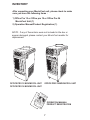
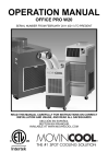
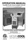
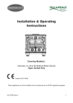
OPERATION MANUAL OFFICE PRO 12 / OFFICE PRO 18 / OFFICE PRO 24 READ THIS MANUAL CAREFULLY FOR INSTRUCTIONS ON CORRECT INSTALLATION AND USAGE AND READ ALL SAFEGUARDS SECCIÒN EN ESPAÑOL SECTION EN FRANÇAIS AVAILABLE AT WWW.MOVINCOOL.COM © 2007 DENSO SALES CALIFORNIA, INC. All rights reserved. This book may not be reproduced or copied, in whole or in part, without the written permission of the publisher. DENSO SALES CALIFORNIA, INC. reserves the right to make changes without prior notice. MovinCool is a registered trademark of DENSO Corporation. OPERATION MANUAL OFFICE PRO 12 / OFFICE PRO 18 / OFFICE PRO 24 Table of Contents FOREWORD................................................................................. 5 Definition of Terms ............................................................... 5 GENERAL WARNINGS & CAUTIONS ........................................ 6 Inventory ................................................................................ 7 INSTALLATION ............................................................................ 8 Choosing an Installation Site .............................................. 8 Moving the Unit ..................................................................... 9 Plugging in the Unit .............................................................. 10 Warning Signal Connection ................................................. 11 Fire Alarm Control Panel Connection.................................. 11 LCDI Power Cord ................................................................... 12 FEATURES................................................................................... 13 OPERATION................................................................................. 14 Control Panel......................................................................... 14 LCD Indicators ...................................................................... 15 Set Clock …………………………...……...…………………….. 16 Operating in COOL Mode ………...……...……………...……. 16 Operating in Fan Only Mode ……………...……………....….. 16 Changing from Fan Only Mode to COOL Mode ….......…… 16 How to Set a Program ……………………………...………….. 17 How to View and Delete Program ……………...……………. 18 How to Run and Stop Program ………………...……………. 18 Operating Modes ……….………………………...…………….. 19 ……………………...…………...…. 20 Empty the Drain Tank Drain Pump Kit (Optional) …………………...……………….. 21 Self-Diagnostic Codes ……………………...…………………. 22 DAILY INSPECTION & MAINTENANCE ………...……………….. 23 ……………………...………...……. 23 Empty the Drain Tank ………………………...……………… 23 Clean the Air Filters Filter Removal Method ………………………...………………. 23 Filter Cleaning Method ………………………...………….…… 24 In-Season/Off-Season Inspection & Maintenance…....…... 24 TROUBLESHOOTING ……………………………………....………. 25 TECHNICAL SPECIFICATIONS………………………...……..…... 26 FOREWORD Congratulations on purchasing the MovinCool portable air conditioner. This manual explains how to install and operate the MovinCool Office Pro12, Office Pro18, and Office Pro24 portable air conditioning units. Please read this operation manual thoroughly to familiarize yourself with the features of the unit and to ensure years of reliable operation. You may also find it useful to keep this operation manual on hand for reference. Components and/or procedures are subject to change without prior notice. Definition of Terms ! WARNING : Describes precautions that should be observed in order to prevent injury to the user during installation or unit operation. ! CAUTION : Describes precautions that should be observed in order to prevent damage to the unit or its components, which may occur during installation or unit operation if sufficient care is not taken. NOTE : Provides additional information that facilitates installation or unit operation. 5 GENERAL WARNINGS & CAUTIONS 1) All electrical work, if necessary, should only be performed by qualified electrical personnel. Repair to electrical components by non-certified technicians may result in personal injury and/or damage to the unit. All electrical components replaced must be genuine MovinCool parts, purchased from an authorized reseller. 2) The proper electrical outlet for MovinCool units must be equipped with a UL approved circuit breaker. 3) Because of potential safety hazards under a certain condition, we strongly recommend against the use of an extension cord. However, if you still elect to use an extension cord, it is absolutely necessary that it will be a UL listed, 3-wire grounding type appliance extension cord, having a 3-blade grounding plug and a 3-slot receptacle that will plug into the appliance. The marked rating of the extension cord should be 115 V, 15A for Office Pro 12, and 115V, 20A for Office Pro 18 and 230V, 20A for Office Pro 24 or equivalent. 4) The Office Pro 12 and Office Pro 18 are equipped with a ten (10) foot (3 meter) UL approved LCDI power cords. The Office Pro 24 is equipped with a six (6) foot (1.8 meter) UL approved LCDI power cord. If replacement, fixed location (hard wired) or power cord lengthening (extension cord) cords are required, contact your reseller or a qualified electrician for approved replacement methods. 5) Never fold or place heavy objects on the power cord. This could result in damage to the power cord causing electrical shock or fire. 6) Do not place water or any other liquid on the unit. This can cause damage to the unit and increase the risk of electrical shock. 7) Do not sit or stand on the unit. 6 INVENTORY After unpacking your MovinCool unit, please check to make sure you have the following items : 1) Office Pro 12 or Office pro 18 or Office Pro 24 MovinCool Unit (1) 2) Operation Manual/Product Registration (1) NOTE : If any of these items were not included in the box or appear damaged, please contact your MovinCool reseller for replacement. MOVINCOOL MOVINCO OL O O OFFICE PRO 12 MOVINCOOL UNIT OFFICE PRO 24 MOVINCOOL UNIT OFFICE PRO 18 MOVINCOOL UNIT OPERATION MANUAL/ PRODUCT REGISTRATION 7 INSTALLATION Choosing an Installation Site ! CAUTION : Following are some precautions to consider before choosing your installation site. Please review carefully as improper installation may result in personal injury or damage to the unit. 1) Do not use the unit in areas where leakage of flammable gas may occur. 2) Do not use the unit in areas where it will be exposed to rain or water. 3) Do not use the unit in an atmosphere of excessively corrosive gas or vapor. 4) Do not use in areas where the temperature is outside the allowable operating range. 5) Do not install the unit in sloping areas. The unit may move or topple over even if the casters are set to the LOCKED position. 6) Install the unit in areas that can with-stand the weight of the unit. The Office Pro 12 unit weighs approximately 200 lbs (91kg), the Office Pro 18 unit weighs approximately 205 lbs (93kg) and the Office Pro 24 unit weighs approximately 252 lbs (114kg) (when the drain tank is full of water). 7) Allow 18 inches of unobstructed airflow for both the air inlets and outlets. 8) Do not use the unit at condition above 95°F 60%RH. 8 INSTALLATION(cont.) Moving the Unit Unlock the casters and push the MovinCool unit using the side handles to a flat, level surface and set the casters back to the LOCKED position. Right Side Handle Left Side Handle MOVINCOO L O UNLOCKED LOCKED 9 INSTALLATION (cont.) Plugging in the Unit 1) Check the prong and surface of the power cord plug for dust/dirt. If dust and/or dirt are present, wipe off with a clean, dry cloth. 2) Check the power cord, plug and prong for damage or excess play. If any damage or excess play is found, contact your MovinCool reseller for repair. WARNING: ! 1) If the power cord or plug is damaged, repair should only be performed by qualified electrical personnel. 2) Do not connect/disconnect the power cord or attempt to operate buttons with wet hands. This could result in electrical shock. ! : CAUTION: 1) Office Pro 12 model ONLY : The AC outlet (115 VAC Single Phase, 60Hz) needs to be rated at 15A or higher. Do not share the outlet with any other instrument or equipment. 2) Office Pro 18 model ONLY : The AC outlet (115 VAC single Phase, 60Hz) needs to be rated at 20A or higher. Do not share the outlet with any other instrument or equipment. 3) Office Pro 24 model ONLY : The AC outlet (208/230 VAC single phase, 60Hz) needs to be rated at 20A or higher. Do not share the outlet with any other instrument or equipment. NOTE : 1) Make sure the AC outlet is free of dirt, dust, oil, or any other foreign matter. 2) The Office Pro 12 model is equipped with a UL approved LCDI cord and an approved NEMA plug configuration (5-15). The appropriate outlet must be used for this plug type. 3) The Office Pro 18 model is equipped with a UL approved LCDI cord and an approved NEMA plug configuration (5-20). The appropriate outlet must be used for this plug type. 4) The Office Pro 24 model is equipped with a UL approved LCDI cord and an approved NEMA plug configuration(6-20). The appropriate outlet must be used for this plug type. 10 INSTALLATION (cont.) Warning Signal Connection (Output Signal terminal L+ and L-)㧖 The controller is equipped with a warning signal output relay type (Form C, normal open dry contact) which can be used to monitor the failure condition. Relay contactor (not connector) is closed when the following condition has occurred : a. Tank Full b. Temperature sensor fails c. High pressure switch error (model OP24 only) The relay output contactor is rated 2A at 30VDC or 2A at 30VAC (resistive load) and it is compatible with various warning devices such as alarm speaker, light indicators, etc. Connecting Warning Signal From Controller㧖 1) Remove service panel from the rear of the unit. 2) Push out the back cap from inside. (In case of hand to remove, please push inner latches of the cap one-by-one) 3) Use recommended warning signal wire size from 16AWG to 26AWG for a solid wire, or 16AWG to 22AWG for a stranded wire with ring terminal for #6 stud size. 4) Connect warning device to terminal L+ and L- according to its polarities. Fire Alarm Control Panel Connection (Input Signal terminal E+ and E-)㧖 The controller is equipped with a normal open input signal, which can be connected directly from the fire alarm control panel. When receiving the signal from the fire alarm control panel, the unit will turn off and will not turn back until it has been RESET. Connecting Fire Alarm Control Panel to Controller㧖 1) Remove service panel from the rear of the unit. 2) Squeeze the inner latches and push out the black cap from inside the panel (See drowing of Cap and inner latch shapes ) 3) Use recommended warning signal wire size from 16AWG to 26AWG for a solid wire, or 16AWG to 22AWG for a stranded wire with ring terminal for #6 stud size. 4) Connect warning device to terminal E+ and E- according to its polarities. 㧖This function is not available in OP12 model Cap } } Latch 11 Input Signal Terminals Output Signal Terminals INSTALLATION (cont.) LCDI Power Cord Instruction ! WARNING The LCDI device is non-serviceable device. Attempting to open the device may expose the user to hazardous of electric shock, and could void warranties of this product. Manufacturer’s reliability is limited to the replacement of the device. ! CAUTION 1. Read the attention print on the device for proper use and handling of this device. 2. This device is used for monitoring leakage current. 3. Do not immerse in water. 4. This device must only be plugged into an appropriate wall outlet. Do not use on extension cords or adapter. Do not remove ground prong. 5. In the event that this device trips, the cause of malfunction should be corrected first before further use. 6. Using the device beyond recommended voltage poses risk to users. 7. Conductors inside this cord are surrounded by shields, which monitor leakage current. These shields are not grounded, and they are periodically examined the cord for any damage. Do not use this product in the event the shields become exposed. 8. Do not push test and/or reset buttons in a short period. PROCEDURE Test device once when AC is installed to assure proper operation. 1. Plug into grounded power receptacle. 2. If light is not on, press reset button once. Light should turn on. 3. Press test button once, light must turn off. 4. Press reset button once again for use. Light should turn on. 5. If test fails, do not use. <FRONT VIEW> TYPE 1 TYPE 2 12 FEATURES For all models: 1) A digital electronic control panel, which allows the user to control the unit’s operation easily. 2) Dual fan speeds (either HIGH or LOW) in both COOL and Fan Only modes. 3) Digital LCD display with blue backlight that indicates: a. Clock with day and time. b. Room Temperature and Set Point Temperature (either Fahrenheit or Celsius). c. Fan Speed Status d. Cool Mode Status e. Program Start time and Stop time f. Program Run and Stop g. Status Codes h. Key Locked option 4) The Set point Temperature can be adjusted between 65°F and 90°F by the SET TEMP buttons. 5) Fire alarm control panel connection ready for automatic shut off.㧖 6) Automatic shut off and warning signal output and alarm for temperature sensor failure, cooling failure.㧖 7) A condensate drain TANK FULL indicator (LED) and display (LCD). 8) An automatic restart feature when the power is lost and regained. The unit will return to the operating mode it was in prior to the loss of power. Any preset program will be retained in the memory in the event power loss occurs. 9) A programmable Clock/Timer function. This allows the user to program a specific time and day that the unit will begin to operate/start and turn off/end (Automatic Operation). 㧖Not available for OP 12 Model. 13 OPERATION Control Panel Before operating the unit, it is important to familiarize yourself with the basic controls located on the control panel. PROGRAM MO TU WE TH FR SA SU AM START STOP CLOCK PROGRAM ON LOCKED PM F C HI LO ON COOL OFF FAN RUN/ STOP F C SET TEMP PROGRAMMING ROOM TEMP SET PROG 8 7 6 TANK FULL FAN MODE 2 SET CLOCK HI/LO 5 SET TEMP COOL MODE 1 ON/OFF ENTER 4 3 1) COOL Mode Button Activates/deactivates the COOL mode/turns the unit off. 2) FAN Mode Button Activates/deactivates the HIGH, LOW, and OFF fan speed. 3) SET TEMP Button ( / ) Temperature Scale Illuminates to indicate the current LED temperatures being displayed are either in °C or °F ; also displays the clock when programming. 4) ENTER Button Press to select set up value 5) SET CLOCK Button To set clock (day and time) 6) SET PROG Button To set or view program 7) RUN/STOP Button Activates/deactivates program(s) 8) TANK FULL LED Flashes when the drain tank is full. 14 OPERATION (cont.) Control Panel (Cont.) LCD Indicators 9 11 12 14 15 16 13 19 10 17 18 9) MO...SU ޓޓޓIlluminates to indicate selected day ޓޓޓof the week 10) °C or °F Temperature displayed in either Fahrenheit or Celsius (See Note) 11) AM/PM Illuminates to indicate AM or PM time of day. 12) PROGRAM Blinking during program editing mode. 13) PROGRAM ON Illuminates to indicate program is running. 14) START Illuminates to indicate program start time. 15) STOP Illuminates to indicate program stop time. 16) CLOCK Illuminates to indicate clock status. 17) FAN HI/LO Illuminates to indicate selected fan speed. 18) COOL ON/OFF Illuminates to indicate cool on or off. 19) LOCKED Illuminates to indicate key lock up. NOTE : ROOM TEMP display range from 16°F to 109°F (-9°C to 42°C) In Fahrenheit only, when display values is greater than 99°F, it will display values of +0F (for 100°F), +1F (for 101°F) and +9F (for 109°F) 15 OPERATION (cont.) Set Clock Prior to operating the Office Pro 12, 18, or 24 users should set the clock of the controller to the correct time as shown in the following steps : 1) Press and hold the SET CLOCK button for 3 seconds or until beep. (LCD will indicate blinking “CLOCK” and blinking “Day of the week ”) AM HI LO ON COOL OFF PROGRAM PM ON LOCKED F C FAN 2) Press SET TEMP buttons to select day of the week. PROGRAM MO TU WE TH FR SA SU START STOP CLOCK RUN/ STOP F C SET TEMP PROGRAMMING ROOM TEMP SET PROG 3) Press ENTER button to set Hour. TANK FULL FAN MODE 4) Press SET TEMP buttons to select desired hour. SET CLOCK HI/LO COOL MODE 5) Press ENTER button to set Minute. Step 2 to 5 SET TEMP ON/OFF ENTER 6) Press SET TEMP buttons to select desired minute. Press SET CLOCK button to exit set clock mode. NOTE: User should check clock periodically to confirm clock accuracy. Operating in COOL Mode 1) The unit can be operated in COOL mode by pressing the COOL ON/OFF button (LCD indicates COOL ON). NOTE : In COOL mode the unit can only be turned off by pressing the COOL ON/OFF button again, not by pressing the fan buttons. 2) Change the fan speed by pressing the fan HI/LO button. 3) Change the temperature set point by pressing the SET TEMP buttons ( / ). NOTE : When turning the unit on, the set point and fan speed are determined by the last operating mode. (program mode not included). Operating in Fan Only Mode 1) The unit can also be operated in Fan Only mode by pressing fan HI/LO button (LCD indicates FAN HI/LO and COOL OFF). 2) The unit can then be turned off by pressing the fan HI/LO button until fan turn off (Fan only mode speed sequence are HI→LO→OFF) Changing from Fan Only Mode to COOL Mode The COOL mode can be activated while the unit is operating in Fan Only mode. To do this, simply press the COOL ON/OFF button (LCD indicates COOL ON). NOTE : The Fan Only mode will not operate after the COOL mode has been activated. After the COOL mode has been activated, the unit cannot be turned off by pressing the fan buttons. The COOL ON/OFF button must be pressed. 16 Step 1 & 6 OPERATION (cont.) How to Set a Program SET START TIME 1) Press and hold the “SET PROG” button for 3 seconds or until beep. 2) Press “SET TEMP” buttons to select day of the week. PROGRAM MO TU WE TH FR SA SU AM START STOP CLOCK HI FAN LO ON COOL OFF PROGRAM PM ON LOCKED F C RUN/ STOP F C SET TEMP PROGRAMMING ROOM TEMP SET PROG Step 1 & 18 TANK FULL 3) Press “ENTER” button. FAN MODE SET CLOCK HI/LO 4) Press “SET TEMP” buttons to select desired hour. 5) Press “ENTER” button. COOL MODE Step 2 to 17 SET TEMP ON/OFF ENTER 6) Press “SET TEMP” buttons to select desired minute. 7) Press “ENTER” button. SET STOP TIME 8) Press “SET TEMP” buttons to select day of the week. 9) Press “ENTER” button. 10) Press “SET TEMP” buttons to select desired hour. 11) Press “ENTER” button. 12) Press “SET TEMP” buttons to select desired minute. 13) Press “ENTER” button. SET FAN SPEED 14) Press “SET TEMP” buttons to select desired fan speed. 15) Press “ENTER” button. SET SET-POINT TEMPERATURE 16) Press “SET TEMP” buttons to select desired temperature. 17) Press “ENTER” button. EXIT PROGRAM EDITING MODE 18) Press “SET PROG” button to exit program editing mode. EDIT MULTIPLE PROGRAMS 19)Repeat step 1) to 18) to set up multiple programs. NOTE: Maximum 7 programming sequences 17 OPERATION (cont.) How to View and Delete Program 1) Press and hold the SET PROG button for 3 seconds or until beep. 2) To view edited program - While pressing and holding the SET PROG button, press SET TEMP ( / ) to scroll program sequence. 3) To delete a program - Press ENTER and SET PROG buttons once simultaneously. 4) To delete multiple program - Press and hold ENTER and SET PROG buttons simultaneously. How to Run and Stop Program 1) Press RUN/STOP button to activate preset program (LCD indicates PROGRAM ON). During RUN program, if user push RESET program run will be terminated, to resume RUN program user must push RUN/STOP button again. 2) Press RUN/STOP button to stop program. NOTE : 1) The unit will return to the previous mode if a program is turned off while it is running. 2) The LCD continues to indicate PROGRAM ON during program activating. 3) Program can be set during power on standby, during unit running, or during program running. 4) During programming, the unit returns to the previous mode if no activity occurs within approximately 3 minutes. 18 OPERATION (cont.) Operating Modes The Office Pro 12, Office Pro 18, and Office Pro 24 can be operated in two modes, Fan Only and COOL. When in Fan Only mode, the unit circulates the surrounding air. When in COOL mode, the compressor is operational and cool air is circulated. 1) COOL Mode Once the compressor has been disengaged for more than 120 seconds, the unit will operate in Fan Only mode for approximately 5 seconds before the compressor re-engages. (Time delay setting is around 120 seconds) 2) Temperature Control The room temperature thermistor monitors the inlet temperature versus SET POINT temperature and switches the unit automatically between COOL and Fan Only modes. 3) Fan Mode Control DIP Switch The Fan Mode Control DIP Switch determines whether the FAN will continue to operate or stop when the compressor cycles off. (SET POINT temperature equals inlet air or room temperature.) The unit has been preset at the factor for continuous fan operation. 4) Temperature Scale Display DIP Switch The Temperature Scale Display DIP Switch changes the temperature(s) that are displayed to either °C or °F . The unit has been preset from the factory to display the temperature(s) in °F. NOTE : If you wish to change the fan mode operation (COOL_OPERATE to COOL_STOP), and/or the Temperature Scale Display (°F to °C), contact your MovinCool reseller. 19 OPERATION (cont.) Empty the Drain Tank During COOL mode, condensate will accumulate in the drain tank. When the drain tank becomes full, the FULL TANK LED will flash and the LCD displays “Tank FL” and the ALARM signal output is turned ON * and the unit will shut off automatically. NOTE : If you want to empty the drain tank, while the unit is in operation, press the COOL ON/OFF button to turn the unit off. * Not available for OP 12 model 1) Open the drain tank door. 2) Pull the drain tank from the unit (display will show “TANK” and ALARM signal output stays ON). 3) Remove the cap and empty the drain tank. CAP 4) Replace the cap and return the drain tank to the unit. 5) Close the drain tank door. 6) Press the COOL ON/OFF button to continue running the unit, display and ALARM signal will return to normal operation. 20 OPERATION (cont) Drain Pump Kit (Optinal) A drain pump kits are available to allow continuous operation and to eliminate the need for a drain tank. When the water collects to level (A) in the pump reservoir, the drain pump begins to operate and discharge the water. NOTE : The compressor will not operate while the drain pump is discharging in water for the Office Pro 12 and Office Pro 18. When the water level drops below level (B), the drain pump stops, and the compressor will restart. NOTE : If the Fan Mode Control DIP Switch is set to the STOP position, the entire unit (including fan operation) will turn off when the drain pump is discharging water. MOVINCO OL &4#+027/2 &4#+027/2 4'5'481+4 O O &+5%*#4)'*15' 21 TROUBLESHOOTING Self-Diagnostic Codes Self-Diagnostic Codes will be displayed on the Control Board under the following conditions: LCD Display Codes Condition When the drain tank switch shuts off the unit LCD displays “TANK FL” and FULL TANK LED flashes. Once emptying the drain tank procedure is completed and “ON/OFF” has been pushed, unit will return to normal operation. When the drain pump malfunctions, the compressor will shut off, and LCD will display “AS”. Once drain pump is fixed and unit has been RESET, the unit will return to normal operation. Contact your MovinCool reseller if problem persists. < Office Pro 24 ONLY > When high pressure switch is activated, display will show “HP” if high pressure switch is activated 3 times in 24 hours, unit will display blinking “HP” and buzzer sound will be on. Unit will return to normal operation after problem is fixed and controller is RESET (See page 25 troubleshooting section). Contact your MovinCool reseller if problem persists. To RESET press FAN HI/LO and COOL ON/OFF buttons simultaneously for 3 seconds, controller will return to normal operation. When room thermistor becomes open or shorted, display will show “OPEN RT” or “SHRT RT” and cool mode operation will be off. Display and cool mode operation will be resumed to normal operation after room thermistor is fixed. Contact your MovinCool reseller if problem persists. When freeze thermistor becomes open or shorted, display will show “OPEN FT” or “SHRT FT” and cool mode operation will be off. Display and cool mode operation will be resumed to normal operation after freeze themistor is fixed. Contact your MovinCool reseller if problem persists. * Not available for OP12 Model 22 DAILY INSPECTION & MAINTENANCE Empty the Drain Tank To empty the drain tank, refer to instruction on page 20. Clean the Air Filters Clean the air filters once a week. If the unit is used in a dusty environment, more frequent cleaning may be required. A dirty air filter can reduce air output resulting in a decrease of the cooling capacity. Filter Removal Method 1) Turn the unit off by pressing the COOL ON/OFF button. If a program is running, you must first press the Program “RUN” button. 2) Remove the two air filters. NOTE : To remove the filter from the Office Pro models, open the front panel and side panel filter doors. On the front panel door, carefully remove the filter retainer from its clips by pulling on the retainer at those two points. On the side panel door, carefully remove the filter element from the wire frame. FRONT PANEL FILTER DOOR SIDE PANEL FILTER DOOR FILTER WIRE FRAME 23 DAILY INSPECTION & MAINTENANCE (cont.) Filter Cleaning Method FI LTER 1) Remove dust from the element with a vacuum cleaner, or rinse in cold or lukewarm water. If the element is extremely dirty, wash with a neutral detergent. 2) After the element has been cleaned, rinse with clean running water, allow to dry, then reinstall. In-Season/Off-Season Inspection & Maintenance In-Season 1) Check the prongs and surface of the power cord plug for dust and/or dirt. If dust and/or dirt are present, wipe off with a clean dry cloth. 2) Check the power cord, plug and prongs for damage or excess play. If any damage or excess play is found, contact your MovinCool reseller for repair. 3) Check the air filters and drain tank. 4) Clean the outside of the unit(s) with a damp cloth or mild nonabrasive cleaner. Off-Season 1) Operate the unit in Fan Only mode for 8 hours. NOTE : Operation is necessary to dry out the inside of the unit. 2) Disconnect the power cord from the AC outlet. 3) Check the prongs and surface of the power cord plug for dust and/or dirt. If dust and/or dirt are present, wipe off with a clean dry cloth. 4) Check the power cord, plug and prongs for damage or excess play. If any damage or excess play is found, contact your MovinCool reseller for repair. 5) Clean the air filters. 6) Empty all water from the drain tank. 24 TROUBLESHOOTING Check the following items before calling a qualified technician SYMPTOM Unit does not operate POSSIBLE CAUSE 1) Ground fault breaker trip or LCDI power cord trip. Reset Breaker or Reset power cold 2) Drain Tank is full (Tank Full LED will be flashing) Empty the drain tank 3) High Pressure Activated 10 times in 24hours. Insufficient Cooling REMEDY 1) Clean air filter. 2) Check inlet and outlet air, and make sure that there were not any object that may prevent air flow into or out from the unit. 3) Check environmental condition whether it is within operation range or not. 4) Reset controller 1) Dirty/Blocked air filters Clean air filter 2) Air Inlet/Outlet blocked Clean air inlet/outlet 3) Improper temperature setting Adjust temperature setting If symptoms persist after the above actions have been taken, turn the unit off, disconnect the power cord plug and contact your MovinCool reseller. 25 TECHNICAL SPECIFICATIONS ITEMS/FEATURES Rating Conditions Dry bulb Wet bulb Humidity ITEMS/FEATURES Specification Power frequency Line voltage Power consumption Current consumption Power factor Starting current Power wiring Cooling Unit Cooling capability Cooling system Blower Type of fan Air volume:Evaporator(High speed) Condenser(High speed) Motor output (High) (Low) Compressor Type Output Refrigerant Type Refrigerant Capacity Safety Devices Compressor overload protector Fan moter protector Anti-freezing thermistor Full drain tank switch Automatic Restart(power interruption) Compressor time delay program High PressureInterruption Signal Input/Output Dimentions & Weight WDH(in) WDH(mm) Weight (lbs/kg) Operating Condition Inlet air (Relative humidity) Control Device Temperature Control Programmable Timer Two Speed Fan Office Pro 12 Office Pro 18 95°F(35°C) 83°F(28.2°C) (60%) Office Pro 12 95°F(35°C) 83°F(28.2°C) (60%) Office Pro 60Hz Single phase 115 V 1.40kw 11.2Amps 92% 66A 14(3-core)AWG 2,950kcal/hr 11,800Btu/hr Direct Expantion Office Pro 24 95°F(35°C) 83°F(28.2°C) (60%) Pro 24 60Hz Single phase 115 V 1.70kw 15.6Amps 95% 65A 12(3-core)AWG 60Hz 1 phase 208/230 V 2.9/2.9kw 14.2/13.1Amps 99%/96% 62A 12(3-core)AWG 4,230kcal/hr 16,800Btu/hr Direct Expantion 5,950/6,050kcal/hr 23,600/24,000Btu/hr Direct Expantion Centrifugal Fan Centrifugal Fan Centrifugal Fan 3 3 3 3 440ft3/min(745m3/h) 540ft /min(917m /h) 630ft3/min(1070m /h) 3 3 3 3 3 870ft /min(1478m /h) 770ft /min(1308m /h) 820ft /min(1398m /h) 0.57kw 0.24kw 0.14kw 0.40kw 0.17kw 0.08kw Hermetic Rotary 0.8kw R-22 0.95lbs(0.43kg) Hermetic Rotary 1.16kw R-410A 1.70lbs(0.77kg) Hermetic Rotary 1.83kw R-410A 1.98lbs(0.90kg) Include Include Include Include Include Include N/A N/A Include Include Include Include Include Include N/A Include Include Include Include Include Include Include Include Include 21”×27”×44” 538×685×1118 165/75 21”×27”×44” 538×685×1118 170/77 21”×27”×47” 538×685×1194 216/98 95°F(35°C) 60% 65°F(18.3°C) 50% Include Include Include 26 95°F(35°C) 60% 65°F(18.3°C) 50% Include Include Include 95°F(35°C) 60% 65°F(18.3°C) 50% Include Include Include THE #1 SPOT COOLING SOLUTION .+/+6'& 9#44#06; DENSO SALES CALIFORNIA, INC. (“DENSO”) warrants its MOVINCOOL Products only to the extent stated in its official written warranties. Unless otherwise specifically provided in writing by DENSO, DENSO warrants to enduser that the Products shall be free of defects in materials or workmanship and will function in accordance with DENSO’s published specifications under ordinary intended use and service for a period of twelve (12) months after delivery to the end-user ; provided, however in the case of the compressor element of the Products such warranty shall be for a period of thirty six (36) months after delivery to the end-user. DENSO shall, at its sole option, repair or replace any defective Product covered by this warranty. Such remedy shall be end-user’s sole remedy with respect to any particular defect in the Products. This warranty does not cover defects or malfunctions which result from causes beyond DENSO’s control, including, without limitation, ()ޓ i unusual physicalor electrical stress ; ( ii ) accident, neglect, abuse, misuse or other abnormal use ; ( iii ) failer to perform routine maintenance in accordance with DENSO’s recommended procedures ; () iv normal wear and tear ; ( v ) repairs or attempted repairs by an unauthorized person ; ( vi )modifications or alterations to the Products ; ( vii)use with supplies or devices not supplied or approved by DENSO ; or ( viii) improper servicing. This warranty shall extend only to the original end-user and shall be void if any labels or other identifying marks permanently affixed to Products when shipped by DENSO are removed, altered, defaced or obliterated. . The aforesaid warranty is the only warranty made by DENSO with respect to the Products and is in lieu of all obligations or liabilities on the part of DENSO for damages arising out of or in connection with the sale, use or performance of the Products, including, without limitation, any lost profits or any other concequential, incidental, special or exemplary damages of any kind. DENSO DISCLAIMS ALL OTHER WARRANTIES WITH REGARD TO THE PRODUCTS, INCLUDING ALL IMPLIED WARRANTIES OF MERCHANTABILITY AND FITNESS FOR USE. THERE ARE NO WARRANTIES WHICH EXTEND BEYOND THE DESCRIPTION CONTAIND HEREIN. PURCHASE DATEAAAAAAAAAAAAAAAAAAAAAAAAAAAAAAAAAAAAAAAAAAAAAAAAAAAAA : SERIAL NUMBERAAAAAAAAAAAAAAAAAAAAAAAAAAAAAAAAAAAAAAAAAAAAAAAAAAAAA : DENSO SALES CALIFORNIA, INC. 3900 Via Oro Avenue Long Beach CA 90810-1868 800-264-9573 / 310-834-6352 www.movincool.com P/N : GX484007- 2111 Second Issue : June 2007