1
INSTRUCTION MANUAL
INTRODUCTION
Thank you for buying the MZ-1 F11 SHARP MZ Disk Drive. This disk drive is
for the SHARP personal computer and provides considerable external storage of
programs and data. Before using the MZ disk drive, please read this manual carefully to ensure correct operation.
The contents of this manual are subject to change without notice.
If the product is defective, please contact the store where you bought it.
SHARP is not responsible for damage incurred during, or as a result of, operation.
CAUTION
'-'
1) Do not use this unit where rapid increases or decreases in temperature occur
or in humid or dusty environment. This unit consists of precision parts, such
as LSI circuits, that can be affected by the operating environment. Do not
expose the unit to direct sunlight.
2) Do not bump or drop this unit, or turn it upside down.
3) Use this device horizontally on a stable, strong support.
4) To prevent electrical noise (RF interference), keep this unit away from all
devices that are likely to generate such.
5) Do not open or push the disk holder during operation (while the BUSY lamp
is on).
6) Be sure to insert the disk along the disk guides for correct insertion. (See page
4. Inserting a disk into the drive.)
7) Clean the head periodically. (See page 6.)
8) Do not operate this unit continuously more than fifty times. If you do, a
malfunction may occur. (Avoid this by programming.)
9) Do not put anything on top of this unit, not even a cloth.
10) Clean the unit with a dry, ~oft cloth. Do not use volatile liquids (alcohol,
benzine, thinner, etc.) or a wet cloth.
11) If MZ disk errors occur frequently, clean the head. If errors continue, contact
the store where you bought the unit.
CONTe:NTS
Parts of the Disk Drive .......•.•.....•.•••..............•.
Connecting the MZ·1 F 11 to a computer .....•..•.•..•.....••...
2
MZ Disk . . . • . . . . . . . . . . . . . . . . . . • . • . . • • . . . . . . . . . . . . . . . .
3
How to clean the disk head .......•.•.•.....•.•.•..••.....••
6
Removing the bottom plate .•...•..•.•••.•...•..•.....••..•
7
Pinout of Connectors .....•.......•.•.....•..•.......•.•.
8
Specifications . . . . . . . . . . . . . . . . . . . . . . . . . . . . . . . . . . . . • . . • •
9
Circuit Diagram . . . . . . • . . . . . . . . . . . . . . • . . • • . . . . . . . . . • . . . • 10
~
'-.
../
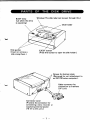
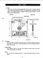
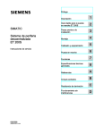
PARTS OF THE DISK DRIVE
BUSY lamp
(Lit wh ile the drive
is operating)
Disk guides
(Insert or remove a
disk along them.)
Window (The disk label can be seen through this.)
EJECT button
(Press this button to open the disk holder.)
Screws for bottom plate
(Removed for unit attachment to
an MZ-700 series computer.)
Cable connector for
connection to interface
(IIF) unit
Connector cover
(Protects the connector for
connecting a data recorder or
supplying external power
(+5 V) to this unit.)
-1-
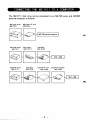
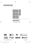
CONNECTING THE MZ-1 F11 TO A COMPUTER
The MZ-l Fll disk drive can be connected to an MZ-700 series and MZ-800
personal computer as follows:
MZ disk drive
MZ-1F11
MZ disk I/F unit
MZ-1E14
H
r-V
~
-,
v
MZ-700 series computer
I
MZ disk drive
MZ-1F11
MZ disk drive
MZ-1F11
Slot cover
(MZ-1X17)
Interface
MZ-1E19
I
Interface
MZ-1E19
Expansion unit
MZ-1 U06
-
2 -
Expansion board
MZ-1 E20
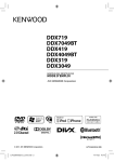
MZ DISK
(1) Disk
This drive uses 2.8-inch double-sided MZ disks. A disk is a flexible magnetic
sheet that stores programs and data. It is permanently contained in a stiff
jacket. The magnetic sheet is viewed th rough the head window. The next
figure shows a standard disk.
Top view
Right view
Head window
Write-protect tab for side A
Write-protect tab for side B
I1-o.---------,--78""'-------->,.,~
Side A label
Drive hole
When the disk is mounted in the disk drive, the rotary spindle of the drive
frts snugly into this hole. The drive's guide pin fits into the guide hole and
helps turn the disk.
Head window
The magnetic head of the disk drive reads and writes data to the disk,
touching it through this window.
Note:
Do not touch the magnetic material - be sure to handle the disk only by its
jacket.
-
3 -
(2) . J""",tin, . the d!,,-, iJ'l.;~~i$k dri".,: "
. '..., . •. ' ..•. ,'
' . Reachhe notes on the instructiOn sheet in a pft!l<ing ease'.
Disk holder
1) Press the EJECT button to open the disk holder.
2) Insert the disk along the disk guides with the head window at the front.
(Hold the disk by the edge of its jacket.) Data can be read or written
on side A or side B. Check the side to be used - it is indicated on the
jacket.
3) Push the disk in lightly until it stops, then close the disk holder. Be sure
to insert the disk along the disk guides. Never close the disk holder unless
the disk is fully inserted.
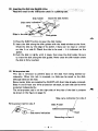
(3) Write-protect tab
This tab is removed to prevent 'data on the disk from being deleted accidentally. When this tab is removed, no data can be saved to the disk,
although data can be read.
Some master disks are supplied by SHARP with their tabs already removed.
Sides A and B have one write protection tab each, so each side can be write
protected independently.
The write-protect tab is on the right side of the side of the disk it protects
(as shown in the figure on page 3).
Side name indication for side A
Write.protect tab for side A
~
name ;nd;cat;on
Recording surface A
-4-
1
J
,I
J
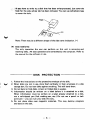
·i;'tt"~ have to write t~ a' disk that has been write-protected, just cover the
hele; fOr the side whose' tab has been removed. You can use cellophane tape
to cover the hole.
Tape~
e
o
Note: There may be a different shape of the side name indication. (*)
(4) Data read/write
The only operation the user can perform on this unit is removing and
inserting disks. All data operations are controlled by the computer. Refer to
the manual for the software in use.
- - - - - - DISK PROTECTION - - - - - - -
V
1. Follow the instructions on the protective envelope of the disk.
2. When disks are not in use, store them vertically in their envelopes in a disk
storage box. Do not lean disks against anything. This will bend them.
3. Do not bend or fold disks. A bent or folded disk is useless.
4. Information should be written on a label before it is attached to a disk.
When information must be written on a label already attached to a disk,
use a soft-tipped pen (felt making pen, etc.) Do not use a pencil or ballpoint pen - you can ruin your disk this way.
S. Do not place disks near magnetic materials. This may destroy programs
and data on the disk.
-5-
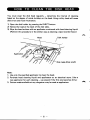
HOW TO CLEAN THE DISK HEAD
You must clean the disk head regularly - determine the interval of cleaning
based on the degree of oxide buildup on the head. Using a dirty head will cause
disk errors and much frustration.
1) Open the disk holder by pressing the EJECT button.
2) Notice the head at the back of the disk table.
3) Wipe the head surface with an applicator moistened with head-cleaning liquid.
(Perform this procedure in the similar way as cleaning a tape recorder head.)
/ Disk holder
Disk table (Disk shaft)
Note:
1. Use only the specified applicator to clean the head.
2. Purchase head cleaning liquid and applicators at an electrical store. (Use a
new applicator for each cleaning - use several if the first one becomes dirty.)
3. Cotton swabs available at any drugstore may be used as applicators.
-
6 -
h
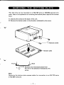
REMOVING
THE
BOTTOM PLATE
This disk drive can be mounted on an MZ-700 series or MZ-800 personal computer. Here is an explanation of removing the bottom plate (required for connection).
1) Unscrew the screws at the back of the unit.
2) Remove the bottom plate in the direction indicated by the arrow.
Bottom plate
Front
1!il~=~======®:...Jb
((===J
C2l
V
Back
Remove only the bottom plate from
the unit in the direction indicated by the
arrow.
Note:
Removing the bottom plate exposes cables for connection to an MZ-700 series
or MZ-800 computer.
-7-
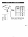
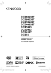
PINOUT OF CONNECTORS
2
To I/F unit
To computer
10
20
COMPONENT
+5V
25
23
S1
21
RESET
19
~
17
M1
15
07
13
06
11
05
04
9
7
03
5
02
01
3
1
00
PATTERN SlOE
26
GNO
24
CE
22
SO
RO
20
IORQ
18
16
GNO
14
GNO
12
GNO
10
GNO
GNO
8
6
GNO
4
GNO
2
GNO
&l
MOTOR
SENSE
5V
WRI TE
READ
This connector is inside the housing of this unit.
To connect this unit to the computer, remove
the bottom plate and pull out the connector.
Connect this connector to the computer.
GND
To data recorder
-
8 -
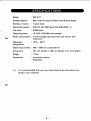
SPECIFICATIONS
Model
: MZ-1F11
Storage capacity
: 64K bytes for each of sides A and B (formatted)
Number of tracks
: 1 spiral track
Recording medium
: 2.8-inch disk (MZ blank disk MZ-6F03) (*)
life time
: 2,000 paths
Operating power
: +5 VDe ± 5%/300 mA (average)
Power consumption: 1.5 W (average) (During motor lock failure: 5 W
maximum)
Operating
temperature
0
: 10 e - 35°e
Operating humidity : 20% - 80% (no condensation)
Dimensions
: 151 mm (width) x 128 mm (depth) x 61 mm (height)
Weight
: 1.2 kg
Accessories
: Instruction manual
Applicator
(*):
It is recommended that you buy blank disks at the store where you
bought your computer.
-
9 -
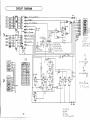
C
CIRCUIT DIAGRAM
'.
• 'i:S245"
\.
17
[illIS
[ill13
lID-
11
lE}
5
6
7
•
V
[00-
19
='-11
V
~
3
~
I
)
I'
....
V
SI
~
CL}, 1
~
!mm-
G
1 19
4
~7
3
~
06
1ID A 115
Os
38
D4
2
D3
39
D2
1
01
TXC
-
RTn
Do
mn
35
Cl
DCD
32 110
33
RXO
17
,
25
19
12
-" ""
"-
"'"-
;) b ~
kc...
r-et:7
(fl-:::: Off'
-1 ~ 0 ....
I~
, --
s cL,.-,,,b
LS04
/" "'..S,h'"
/1,0"'-.
• ~::_~
~(' 1)( 0-\ ~
'Il
I
iCA-'SV
w,~
6
Vcr.
7
3;b,,~
In
I
OB QA I
LS393
DUC
}h
rJ
WRI TE
.5 V
SENSE
MOTOR
-=
~
26
24
22
20
17 TT
1
16
14
2
10
15
13
Il
,
T- 2
)
1
2
N
3
N C
N C
C
4 MOTOR
5 SU'R[
6
• 5 V
7 .RIT[
• • WAD
9 1:. D
00
0
7
5
3
::-'
,
D
D
0
0
0
0
0
0
7
6
5
4
3
2
1
0
en
l/:Dsr
~LS04
4511
~
Cl
110
e
6
4
2
N'O
NO
N D
NO
NO
co N 0
G NO
(, NO
o
CK
L S 7A
({;' 0~
\.9
\..J)
\. eLc).,:*:P'~
LS74
Cl(
i-
,...-..
'\
C)
XJ)
ail
I
6
'
~
LS14
~
~
H
CL:.....
D
L SVCK
/4
Q
ll:
~
H
L,L-
C{-viP---,
...£k-
~-
C
Q
'\ 1~J Y
LS04
-b~
~S74
o vCK
L S 74
:
Q
LS74
C<.l~ ~ )
'])-::::/10/[, 5(;~:5~c...
J
,,+;30
Q
c;.
UiJ
e iORa
,1
Voyt.--, ot V) d-' •
L,C-
Vl/\
SO
G
G
G
G
G
H
~
o VCK
iH
~
-=r
S 74 U
L
I"
v
-p
r+D--.~
LS74~,.-
I ~~>-
4,7K
~
\\hSI4
H
Q P1l
D....,-~
LS741S - '
-;-;..
H
LS74~
3
J;30
LS04
L S 04
~
1.$14
L504
60 N A NJ)
o~worx.
()~ I'f")v.
lVA,rvljj
-1l/
f (
I
"
-.-.l
1.::....
"/0
)
100
=~
~~
~
- 10-
:;;.1)15 6
hi
LS 04..
JL
<j
G ND
S
)
1
Al, ~8.
('J(l
h5
.-I1-lii:1 ~
AI
'"
I
r.7
~
'P ')
I-!L"""~'-i ~R.
10
3,~nc..
.sy
:~
..... f--
'~
a.::..1-!!.l~H
.;:
~LS04~SI4
2S t 5 V
S 1
23
21 11 E SET
19
'"
B
~L-L,-Q...
CONNECTOR - 5
CIII'FONENT-SIDE PATTERN-S I DE
O-f-O-r-O-r-
~
ii
[tit
';
~'
2es ( Ol-rvi- C~~031-1~SkG
X'TAL
os C 6.SMHI
~
T- 1
G N D
11 EA D
'-0
LS74
21.
-"
V
LS393C~ A::: &-1~,:S k;.<:.
~
13 :::. Lt ()~ L ii.S le...
C.(I
1
~
Plf
8 9 IQ 11
4 3r--
.sv
1
2
3
4
S
6
T- 4
.~,~
1-1 /) vv.. a.
-'
",,1) -
~
LSIM
I1I'lt-nr -
....
"-
"l5'I'n ~4
"t~~T
... AD /[
'"
RJ[;A 13
2n d,u
A
In
36
RIll
34 8/1.
21
11,,1-. 0--
,
.-
14
LH 0084
22
DCD8
-~.~
Y/ V':-te ¥n y ,'?-tr C-t
.18 ..
&1$....
D7
)
I YJ v Sc.!,I11I.1:'tT,r,
:i)
IJ
rt1,.i.A
~
....J
SHARP CORPORATION
OSAKA, JAPAN
Printed in Japan
Gedruckt in Japal'l
Imprime au Japen
Stampato in Giappone
© 1984
SHARP CORPORATION
@
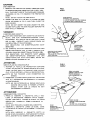
CAUTION:
DISK INSERTION
1. REMOVE THE PROTECTIVE SHEET INSERTED PRIOR
TO SHIPPING BEFORE INSERTING THE FLOPPY DISK.
FIG.1
ABB.1
PULL THE RIGHT SIDE OF THE CARRIAGE FORWARD
AS SHOWN IN FIG.1 TO REMOVE THE PROTECTIVE
SHEET.
DISK SHAFT
SPINDELHAL TERUNG
L'AXE D'INSERTlON DU DISQUE
L'ALBERO DEL DISCHETTO
NOTE: DO NOT TOUCH THE DISK SHAFT.
2.
INSERT THE DISK ALL THE WAY IN ALONG THE DISK
GUIDE AS SHOWN IN FIG. 2, AND THEN CLOSE THE
DISK HOLDER.
NOTE: DO NOT INSERT THE DISK UNDER THE DISK
GUIDES NOR CLOSE THE DISK HOLDER BEFORE THE
DISK IS FULLY INSERTED.
VORSICHT:
EINSETZEN DER DISKETTE
.."J......VOR
DEM EINSETZEN DER DISKETTE DAS SCHUTZ-
aLATT,
i'
'-.
DAS
ENTFERNEN.
ZUR
TRANSPORTSICHERUNG
DIE RECHTE SEITE
DIENT,
DES SCHLlTTENS
WIE IN ABB. 1 GEZEIGT NACH VORNE ZIEHEN, UM
DAS SCHUTZBLATT ZU ENTFERNEN.
ZUR
BEACHTUNG:
DIE
DISKETTENACHSE
NICHT
CARRIAGE
SCHLITTEN
CHARIOT
CARRELLO
BERUHREN.
2. DIE DISKETTE BIS ZUM ANSCHLAG ENTLANG DER
DISKETTENFUHRUNG WIE
IN ABB. 2 GEZEIGT EIN-
FUHREN. DANN DEN DISKETTENHAL TER SCHLlEBN.
ZUR
DIE
BEACHTUNG:
DIE
DISKETTE
DISKETTENFUHRUNG
DISKETTENHAL TER
NICHT
EINSETZEN
UNTER
UNO
DEN
PROTECTIVE SHEET
SCHUTZBLATT
FEUILLE DE PROTECTION
PROTEZIONE
j
NICHT SCHLlEBEN, BEVOR DIE
DISKETTE GANZ EINGESETZT 1ST.
I
/
ATTENTION:
MISE EN PLACE DU DISQUE SOUP LE
1. RETIRER
LA FEUILLE DE PROTECTION D'ORIGINE
FIG.2
ABB.2
AVANT DE METTRE LE DISQUE SOUPLE EN PLACE.
TIRER LE c6TE DROIT DU CHARIOT VERS L'AVANT
DISK HOLDER
DISKETTENHAL TER
PORTE-DISQUE
PORTADISCHETTO
(FIG. 1) POUR RETIRER LA FEUILLE DE PROTECTION.
-""",,NOTE: NE
!'"
PAS TOUCHER
L'AXE
D'INSERTION
DU
DISQUE.
2. PRESENTER LE DISQUE SOUPLE DEVANT LES GUIDES
(FIG. 2), L'INTRODUIRE ENTIEREMENT, ET FERMER
LE PORTE-DISUQE.
NOTE: NE PAS INTRODUIRE LE DISQUE SOUPLE EN
DEHORS DES GUIDES, NI FERMER LE PORTEDISQUE
AVANT
QUE
LE
DISQUE
NE
SOIT
ENTIEREMENT INTRODUIT.
ATTENZIONE:
INSERIMENTO DEL DISCHETTO
1. PRIMA
01
INSERIRE
IL
LIERE LA PROTEZIONE
DISCHETTO, DALLA TOGINSERITA DALLA FABBRI-
CA. PER TOGLlERLA, TIRARE IN AVANTI LA PARTE
DESTRA DEL
CARRELLO
COME ILLUSTRATO
DISK GUIDE
DISKETTENFUHRUNG
GUIDE
GUIDE DEL DISCHETTO
IN
FIGURA 1.
NOTA: NON TOCCARE L'ALBERO DEL DISCHETTO.
2.
INSERIRE IL DISCHETTO LUNGO LE GUIDE,
ILLUSTRATO IN FIGURA 2, E CHIUDERE
COME
IL PORTADI-
SCHETTO.
NOTA: NON
INSERIRE
IL
DISCHETTO
SOTTO
LE
GUIDE E NON CHIUDERE IL PORTADISCHETTO PRIMA
CHE IL DISCHETTO SIA
INS~RITO
COMPLETAMENTE.
DISK
DISKETTE
DISQUE SOUPLE
DISCHETTO