1
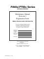
PA40x/PT40x Series
PORTABLE PRINTERS
Maintenance Manual
Revision 3
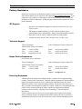
Registration Form
=(%5$7(&+12/2*,(6&25325$7,21
To receive maintenance manual revisions
and updates, complete this form and fax
or mail it to Zebra Technologies at the
fax number or address shown below.
COMPANY
ADDRESS
CITY
STATE, ZIP
PHONE #
(
)
CONTACT:
Zebra Technologies Corporation
30 Plan Way
Warwick, RI 02866-1012 U.S.A.
ATTN: Technical Training Department
FAX NUMBER: +1.401.732.7808
505142L Rev. 3 5/03
i
127(6
505142L Rev. 3 5/03
7DEOHRI&RQWHQWV
Table of Contents
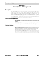
Section 1 Description of Equipment
Description............................................................................................................................. 1-1
Printer Operating Modes........................................................................................................ 1-1
Printing Method ..................................................................................................................... 1-1
Specifications......................................................................................................................... 1-2
Electronics System Block Diagram ....................................................................................... 1-5
Section 2 Operation Overview
Operator Controls .................................................................................................................. 2-1
Install Battery ............................................................................................................ 2-2
Charge Battery .......................................................................................................... 2-3
Universal Battery Charger ........................................................................................ 2-3
Extending Battery Life .............................................................................................. 2-4
Printer Overview.................................................................................................................... 2-5
Load Supplies ........................................................................................................................ 2-6
Tear-Off Mode .......................................................................................................... 2-6
Peel-Off Mode .......................................................................................................... 2-9
Load Ribbon ........................................................................................................... 2-11
Initial Power Up................................................................................................................... 2-13
Print Test Label ....................................................................................................... 2-13
Connect Computer ............................................................................................................... 2-15
Set Communication Parameters .............................................................................. 2-16
Calibrate .................................................................................................................. 2-16
Calibrate Ribbon Sensor ......................................................................................... 2-18
Setup Software ..................................................................................................................... 2-18
Operate Printer ..................................................................................................................... 2-19
Adjust Darkness ...................................................................................................... 2-19
Adjust Printhead Pressure ....................................................................................... 2-19
/5HY
L
7DEOHRI&RQWHQWV
Adjust Faststrap ................................................................................................................... 2-20
Convert to a Shoulder Strap .................................................................................... 2-20
Convert to a Hand Strap .......................................................................................... 2-21
Section 3 Troubleshooting
Troubleshoot .......................................................................................................................... 3-1
LEDs ......................................................................................................................... 3-1
Factory Assistance ................................................................................................................. 3-4
ZIP Support ............................................................................................................... 3-4
Technical Support ..................................................................................................... 3-4
Repair Service Department ....................................................................................... 3-4
Returning Equipment ................................................................................................ 3-4
Section 4 Maintenance
Preventive Maintenance Schedule ............................................................................ 4-5
Battery Maintenance ................................................................................................. 4-6
Lubrication ................................................................................................................ 4-6
Corrective Maintenance ............................................................................................ 4-7
Remove/Install Shoulder Strap ................................................................................. 4-8
Disassemble/Assemble Printer ................................................................................. 4-9
Route Battery Access Door Replace ....................................................................... 4-12
Replace Main Logic Board ..................................................................................... 4-13
Replace Power Supply Board ................................................................................. 4-15
Replace Printhead Assembly .................................................................................. 4-17
Replace Ribbon Sensor Board Assembly ............................................................... 4-19
Replace Print Mechanism Module .......................................................................... 4-22
Replace Wiring Harness ......................................................................................... 4-23
Replace Membrane Switch Assembly .................................................................... 4-26
Repair Media Guide ................................................................................................ 4-28
IrDA Board and Cable Replacement ...................................................................... 4-30
LL
/5HY
7DEOHRI&RQWHQWV
Section 5 Maintenance and Assembly Drawings
Drawing and Parts List .......................................................................................................... 5-1
Power Supply Board Layout ..................................................................................... 5-6
Main Logic Board Layout ......................................................................................... 5-7
/5HY
LLL
7DEOHRI&RQWHQWV
LY
/5HY
/LVWRI)LJXUHV
/LVWRI)LJXUHV
Figure 1-1. Adapter Cable Pinouts. . . . . . . . . . . . . . . . . . . . . . . . . . . . . . . . . . . . . . . . . . . . . . . . . . 1-3
Figure 1-2.Null Modem Cables . . . . . . . . . . . . . . . . . . . . . . . . . . . . . . . . . . . . . . . . . . . . . . . . . . . . 1-4
Figure 1-3.PA/PT40x Electronics System Block Diagram . . . . . . . . . . . . . . . . . . . . . . . . . . . . . . . . 1-5
Figure 2-1.Operator Controls . . . . . . . . . . . . . . . . . . . . . . . . . . . . . . . . . . . . . . . . . . . . . . . . . . . . . . 2-1
Figure 2-2.Battery Charger Receptacle. . . . . . . . . . . . . . . . . . . . . . . . . . . . . . . . . . . . . . . . . . . . . . . 2-1
Figure 2-3.Install Battery . . . . . . . . . . . . . . . . . . . . . . . . . . . . . . . . . . . . . . . . . . . . . . . . . . . . . . . . . 2-2
Figure 2-4.Connecting Battery Charger . . . . . . . . . . . . . . . . . . . . . . . . . . . . . . . . . . . . . . . . . . . . . . 2-4
Figure 2-5.Printer Overview . . . . . . . . . . . . . . . . . . . . . . . . . . . . . . . . . . . . . . . . . . . . . . . . . . . . . . . 2-5
Figure 2-6.Open Media Access Door . . . . . . . . . . . . . . . . . . . . . . . . . . . . . . . . . . . . . . . . . . . . . . . . 2-7
Figure 2-7.Raise Printhead Assembly . . . . . . . . . . . . . . . . . . . . . . . . . . . . . . . . . . . . . . . . . . . . . . . 2-7
Figure 2-8.Load Media . . . . . . . . . . . . . . . . . . . . . . . . . . . . . . . . . . . . . . . . . . . . . . . . . . . . . . . . . . . 2-8
Figure 2-9.Install/Remove Tear Blade . . . . . . . . . . . . . . . . . . . . . . . . . . . . . . . . . . . . . . . . . . . . . . . 2-8
Figure 2-10.Media Over Tear Blade . . . . . . . . . . . . . . . . . . . . . . . . . . . . . . . . . . . . . . . . . . . . . . . . . 2-9
Figure 2-11.Store Tear Blade . . . . . . . . . . . . . . . . . . . . . . . . . . . . . . . . . . . . . . . . . . . . . . . . . . . . . 2-10
Figure 2-12.Thread Liner Peel-Off Mode. . . . . . . . . . . . . . . . . . . . . . . . . . . . . . . . . . . . . . . . . . . . 2-10
Figure 2-13.Insert Ribbon Cartridge. . . . . . . . . . . . . . . . . . . . . . . . . . . . . . . . . . . . . . . . . . . . . . . . 2-11
Figure 2-14.Operate Position (Ribbon Cartridge) . . . . . . . . . . . . . . . . . . . . . . . . . . . . . . . . . . . . . 2-12
Figure 2-15.Close Printhead and Cover . . . . . . . . . . . . . . . . . . . . . . . . . . . . . . . . . . . . . . . . . . . . . 2-12
Figure 2-16.Sample Configuration Label . . . . . . . . . . . . . . . . . . . . . . . . . . . . . . . . . . . . . . . . . . . . 2-13
Figure 2-17.Sample ASCII/Hex Data Received Label . . . . . . . . . . . . . . . . . . . . . . . . . . . . . . . . . . 2-13
Figure 2-18.Serial Cable Hookup . . . . . . . . . . . . . . . . . . . . . . . . . . . . . . . . . . . . . . . . . . . . . . . . . . 2-15
Figure 2-19.Sample Media Profile . . . . . . . . . . . . . . . . . . . . . . . . . . . . . . . . . . . . . . . . . . . . . . . . . 2-18
Figure 2-20.Printhead Pressure Adjustment . . . . . . . . . . . . . . . . . . . . . . . . . . . . . . . . . . . . . . . . . . 2-19
Figure 2-21.Convert to a Shoulder Strap . . . . . . . . . . . . . . . . . . . . . . . . . . . . . . . . . . . . . . . . . . . . 2-20
Figure 2-22.Convert to a Hand Strap . . . . . . . . . . . . . . . . . . . . . . . . . . . . . . . . . . . . . . . . . . . . . . . 2-21
Figure 4-1.Clean Head-Open Sensor . . . . . . . . . . . . . . . . . . . . . . . . . . . . . . . . . . . . . . . . . . . . . . . . 4-6
Figure 4-2.Identify Parts and Assemblies. . . . . . . . . . . . . . . . . . . . . . . . . . . . . . . . . . . . . . . . . . . . . 4-7
Figure 4-3.Remove/Install Shoulder Strap . . . . . . . . . . . . . . . . . . . . . . . . . . . . . . . . . . . . . . . . . . . . 4-8
Figure 4-4.Power Supply Board Layout . . . . . . . . . . . . . . . . . . . . . . . . . . . . . . . . . . . . . . . . . . . . . 4-10
Figure 4-5.Remove/Install Power Supply Board and Main Logic Board. . . . . . . . . . . . . . . . . . . . 4-11
Figure 4-6.Remove/Install Print Mechanism Module . . . . . . . . . . . . . . . . . . . . . . . . . . . . . . . . . . 4-12
Figure 4-7.Remove/Install Battery Access Door . . . . . . . . . . . . . . . . . . . . . . . . . . . . . . . . . . . . . . 4-13
Figure 4-8.Route Cable Harness . . . . . . . . . . . . . . . . . . . . . . . . . . . . . . . . . . . . . . . . . . . . . . . . . . . 4-14
Figure 4-9.Disassemble/Assemble Power Supply Board & Main Logic Board. . . . . . . . . . . . . . . 4-16
Figure 4-10.Remove/Install Printhead Assembly . . . . . . . . . . . . . . . . . . . . . . . . . . . . . . . . . . . . . . 4-18
/5HY
Y
/LVWRI)LJXUHV
Figure 4-11.Locate Printhead Ground Wire . . . . . . . . . . . . . . . . . . . . . . . . . . . . . . . . . . . . . . . . . . 4-18
Figure 4-12.Locate Printhead 16-Pin Connector . . . . . . . . . . . . . . . . . . . . . . . . . . . . . . . . . . . . . . 4-20
Figure 4-13. Remove Ribbon Sensor Board . . . . . . . . . . . . . . . . . . . . . . . . . . . . . . . . . . . . . . . . . . 4-21
Figure 4-14.Install Ribbon Sensor Board . . . . . . . . . . . . . . . . . . . . . . . . . . . . . . . . . . . . . . . . . . . . 4-21
Figure 4-15.Sensor Connector Location . . . . . . . . . . . . . . . . . . . . . . . . . . . . . . . . . . . . . . . . . . . . . 4-25
Figure 4-16.Removing the Access Door Top . . . . . . . . . . . . . . . . . . . . . . . . . . . . . . . . . . . . . . . . . 4-25
Figure 4-17.Membrane Switch Assembly . . . . . . . . . . . . . . . . . . . . . . . . . . . . . . . . . . . . . . . . . . . 4-27
Figure 4-18.Adjust Media Guide . . . . . . . . . . . . . . . . . . . . . . . . . . . . . . . . . . . . . . . . . . . . . . . . . . 4-29
Figure 4-19.Install IrDA Cable and Board . . . . . . . . . . . . . . . . . . . . . . . . . . . . . . . . . . . . . . . . . . . 4-30
Figure 4-20.Mounting Hole Template . . . . . . . . . . . . . . . . . . . . . . . . . . . . . . . . . . . . . . . . . . . . . . 4-31
Figure 5-1. Main Printer Drawing . . . . . . . . . . . . . . . . . . . . . . . . . . . . . . . . . . . . . . . . . . . . . . . . . . 5-3
Figure 5-2. Option and Accessory Kits . . . . . . . . . . . . . . . . . . . . . . . . . . . . . . . . . . . . . . . . . . . . . . 5-5
Figure 5-3.Power Supply Board Layout . . . . . . . . . . . . . . . . . . . . . . . . . . . . . . . . . . . . . . . . . . . . . . 5-6
Figure 5-4.Main Logic Board Layout. . . . . . . . . . . . . . . . . . . . . . . . . . . . . . . . . . . . . . . . . . . . . . . . 5-7
YL
/5HY
'HVFULSWLRQRI(TXLSPHQW
6HFWLRQ
6HFWLRQ
'HVFULSWLRQRI(TXLSPHQW
'HVFULSWLRQ
The Zebra PA40x Series is a low-cost, portable, direct thermal printer. The Zebra
PT40x Seriesis a low-cost, portable, thermal transfer printer. Both can be carried
by the shoulder strap, sit on a workspace, or be mounted to a specific location. The
battery makes them truly portable especially in environments where AC power is
not readily available. The PA/PT40x Series deliver traditional Zebra reliability in a
transportable label printer for the mobile work environment.
3ULQWHU2SHUDWLQJ0RGHV
•
Tear-Off Mode. The operator tears off a single label (or a strip of labels) after
printing.
•
Peel-Off Mode. The liner is peeled away from the label as it prints, the printer
waits until the operator removes the label, and then the next label prints.
•
Direct Thermal Printing (PA40x Series) (requires direct thermal media). A
substrate, typically paper, is coated with a chemical that changes to a dark
color upon exposure to heat over a period of time to form an image.
•
Thermal Transfer Printing (PT40x Series) (requires thermal transfer media
and ribbons). An image is formed by the heat of the printhead transferring to
the ribbon, releasing ink directly to the substrate to produce the printed image.
3ULQWLQJ0HWKRG
/5HY
=HEUD3$37[6HULHV0DLQWHQDQFH0DQXDO
3DJH
6HFWLRQ
'HVFULSWLRQRI(TXLSPHQW
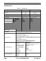
6SHFLILFDWLRQV
7DEOH6SHFLILFDWLRQV
3ULQWGHQVLW\
3ULQWZLGWK
GRWVLQ
GRWVPP
LQWRLQ
PPWRPP
LQVHF
PPVHF
RU
RU
3ULQWVSHHG
LQVHF
PPVHF
/DEHOZLGWK,QFOXGLQJOLQHU
LQWRLQ
PPWRPP
/DEHOOHQJWKVWDQGDUGPHPRU\
LQWRLQ
PPWRPP
,QWHUODEHOJDS
LQWRLQ
PPWRPP
/DEHOWKLFNQHVV
LQWRLQ
PPWRPP
0D[RXWHUGLDPHWHU
LQ
PP
/DEHOUROOVL]H
&RUHLQQHUGLDPHWHU
LQ
PP
+RUL]RQWDO
LQ
PP
5HJLVWUDWLRQWROHUDQFH
9HUWLFDO
LQ
PP
'LVWDQFHIURPFHQWHUSULQWHOHPHQWWRFHQWHURIODEHO LQ
PP
3K\VLFDOVL]H/î:î+
LQîLQîLQ PPîPPîPP
:HLJKWZLWKRXWPGLD
OEV
NJ
2SHUDWLQJWHPSHUDWXUHUDQJH
WR)
WR&
6WRUDJHZLWKEDWWHU\WHPSHUDWXUHUDQJH
±WR)
±WR&
6WRUDJHZLWKRXWEDWWHU\WHPSHUDWXUHUDQJH
±WR)
±WR&
2SHUDWLRQ
WRQRQFRQGHQVLQJ
5HODWLYHKXPLGLW\
6WRUDJH
WRQRQFRQGHQVLQJ
=HEUDIRQWV$%&'(+*6
)RQWVDYDLODEOH
&*7ULXPYLUDWH%ROG&RQGHQVHGVFDODEOHVPRRWK
=HEUDUHFRPPHQGVXVLQJ=HEUDEUDQGGLUHFWWKHUPDOUROOPHGLDWKDWLV
RXWVLGHZRXQG0HGLDPD\EHWUDQVPLVVLYHRUUHIOHFWLYHEODFNPDUNVHQVLQJ
FRQWLQXRXVGLHFXWRUQRWFKHG
)RUGLHFXWODEHOVXVHRQO\WUXHDXWRGLHV
1RWFKHGPHGLDPXVWKDYHDLQPPZLGHîLQPPORQJ
0HGLDUHTXLUHPHQWV
FXWRXWLQWKHFHQWHURIWKHUROO7KHUHIOHFWLYHPHGLDEODFNPDUNVPXVWEHLQWKH
FHQWHURIWKHUROO
0LQLPXP%ODFN0DUN'LPHQVLRQV
0DUNZLGWKLQPPSHUSHQGLFXODUWRHGJHRIPHGLD
0DUNKHLJKWLQPPSDUDOOHOWRHGJHRIPHGLD
&RGDEDUVXSSRUWVUDWLRVRI ,QGXVWULDORI
WR
6WDQGDUGRI
&RGH
,QWHUOHDYHGRIVXSSRUWVUDWLRVRIWR
&RGH86'VXSSRUWV 0RGXOXV&KHFN'LJLW
VHULDOL]DWLRQLQDOOVXEVHWV
/2*0$56
DQG8&&&DVH&RGHV
06,
%DUFRGHVDYDLODEOH'
&RGHVXSSRUWVUDWLRVRI 3OHVVH\
WR
32671(7
&RGH
83&(
($1-$1
83&($1([WHQVLRQV
($1-$1
($183&$
&RGDEORFN
0LFUR3')
&RGH
3')
%DUFRGHVDYDLODEOH'
'DWD0DWUL[
45FRGH
0D[LFRGH
3DJH
=HEUD3$37[6HULHV0DLQWHQDQFH0DQXDO
/5HY
'HVFULSWLRQRI(TXLSPHQW
6HFWLRQ
7DEOH6SHFLILFDWLRQV&RQWLQXHG
5RWDWLRQDQJOHV
520PHPRU\VWDQGDUG
5$0PHPRU\VWDQGDUG
DQG
0%3$37²0%3$37
.%3$37²0%3$37
6WDQGDUG%DWWHU\²9'&P$K1L&G%DWWHU\
([WHQGHG/LIH%DWWHU\²9'&P$K1L&G%DWWHU\
(OHFWULFDO
9$&+]%DWWHU\&KDUJHU
8QLYHUVDO%DWWHU\&KDUJHU±9$&±+]
&RPPXQLFDWLRQV
565-VHULDOSRUWZLWKSLQV
'DWDVSHHGPD[LPXP
%DXG
3URFHVVRU
ELW5,6&0LFURFRQWUROOHUZLWKELWGDWDEXVDUFKLWHFWXUH
8/0HGLFDO(TXLSPHQW6WDQGDUG3DUW
&6$1R&DQDGLDQ6DIHW\6WDQGDUG
,(&(1,QWHUQDWLRQDO6DIHW\6WDQGDUG
)&&3DUW6XESDUW$/HYHO$(OHFWURPDJQHWLF5DGLDWLRQ6WDQGDUG
)&&3DUW6XESDUW%/HYHO$(OHFWURPDJQHWLF5DGLDWLRQ6WDQGDUG
$JHQF\DSSURYDOV
&DQDGLDQ'2&&ODVV$
8/UG(GLWLRQ'RPHVWLF6DIHW\6WDQGDUG
625&DQDGLDQ(OHFWURPDJQHWLF5DGLDWLRQ6WDQGDUG
(1,QWHUQDWLRQDO,PPXQLW\6WDQGDUG
(1&ODVV%(XURSHDQ(OHFWURPDJQHWLF5DGLDWLRQ6WDQGDUG
5LEERQZLGWK
LQ
PP
5LEERQRXWHUGLDPHWHU
LQ
PP
&DUU\LQJVWUDS
LQZHEZLGWK
PPZHEZLGWK
0HHWV)&&6XESDUW$ZKHQXVLQJXQVKLHOGHGFDEOHVDQGWKH9$&%DWWHU\&KDUJHU
0HHWV)&&6XESDUW%ZKHQXVLQJVKLHOGHGFDEOHVDQGWKH8QLYHUVDO%DWWHU\&KDUJHU
6HH)LJXUH RQSDJHIRUDKROHGULOOLQJWHPSODWHIRUPRXQWLQJWKH3$37[
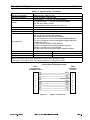
9-Pin D-Sub to RJ45 Adapter Cable
DB-S
Connector to
Null Modem Cable
2
DCD
RXD
DCD
RXD
2
3
TXD
TXD
3
4
DTR
DTR
4
5
GND
GND
5
6
DSR
DSR
6
7
RTS
RTS
7
8
CTS
CTS
8
1
Figure 1-1.
/5HY
RJ45
Connector
to Printer
1
Adapter Cable Pinouts
=HEUD3$37[6HULHV0DLQWHQDQFH0DQXDO
3DJH
6HFWLRQ
'HVFULSWLRQRI(TXLSPHQW
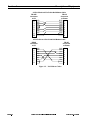
25-Pin D-Sub to 9-Pin D-Sub Null Modem Cable
DB-25P
Connector
to PC
2
3
4
5
6
7
8
20
DB-9S
Connector
to Printer
TXD
RXD
RTS
CTS
DSR
GND
DCD
DTR
DCD
RXD
TXD
DTR
GND
DSR
RTS
CTS
1
2
3
4
5
6
7
8
9-Pin D-Sub to 9-Pin D-Sub Null Modem Cable
DB-9S
Connector
to PC
1
2
3
4
5
6
7
8
DB-9P
Connector
to Printer
DCD
RXD
TXD
DTR
GND
DSR
RTS
CTS
DCD
RXD
TXD
DTR
GND
DSR
RTS
CTS
1
2
3
4
5
6
7
8
Figure 1-2. Null Modem Cables
3DJH
=HEUD3$37[6HULHV0DLQWHQDQFH0DQXDO
/5HY
'HVFULSWLRQRI(TXLSPHQW
6HFWLRQ
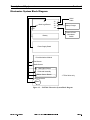
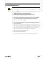
(OHFWURQLFV6\VWHP%ORFN'LDJUDP
J1
Main Logic Board
J2
J5
J9
J7
Serial
Cable
Battery Charger
J12
Battery
Power & Feed
Membrane
Switch
Power Supply Board
Print Mechanism Module
Peel Sensor
Media Sensor
Head-Open Sensor
Printhead Assembly
Ribbon Sensor Board *
* PT40x Series only
4 Wire Connector
Motor
Figure 1-3. PA/PT40x Electronics System Block Diagram
/5HY
=HEUD3$37[6HULHV0DLQWHQDQFH0DQXDO
3DJH
6HFWLRQ
3DJH
'HVFULSWLRQRI(TXLSPHQW
=HEUD3$37[6HULHV0DLQWHQDQFH0DQXDO
/5HY
6HFWLRQ
2SHUDWLRQ2YHUYLHZ
6HFWLRQ
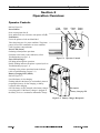
2SHUDWLRQ2YHUYLHZ
2SHUDWRU&RQWUROV
Refer to Figure 2-1.
Power Button
Press to turn printer On (O).
Press and hold for two seconds to turn printer Off (2).
Feed Button
Forces the printer to feed one blank label.
Takes the printer out of a pause condition. The printer
pauses from a ZPL command or an error condition.
Used for printer setup and status.
Power LED (Green)
On during normal printer operations.
Functions as the battery status indicator (refer to
Troubleshooting on page 3-1).
Error LED (Orange)
Off during normal printer operation.
Double flashing indicates the printer is paused (refer to
Troubleshooting on page 3-1).
Functions as the printer operational status indicator
(refer toTroubleshooting on page 3-1).
Battery Charging LED (Yellow)
Refer to Figure 2-2.
On while battery is fast charging.
Flashing indicates the battery is not installed, printer is
preparing the battery for fast charging, or battery
overheats while charging.
Off if the battery is fully charged or the battery charger
is not plugged in. If the battery charger is plugged in,
the battery receives a continuous maintenance charge.
Feed
Button
Error
LED
Power
LED
Power
Button
Figure 2-1. Operator Controls
Receptacle
Battery Charging LED
Figure 2-2. Battery Charger Receptacle
3DJH
=HEUD3$37[6HULHV0DLQWHQDQFH0DQXDO
/5HY
6HFWLRQ
2SHUDWLRQ2YHUYLHZ
,QVWDOO%DWWHU\
7KH(3$FHUWLILHG5%5&%DWWHU\5HF\FOLQJ6HDORQWKHQLFNHOFDGPLXP1L&GEDWWHU\
LQGLFDWHV=HEUD7HFKQRORJLHVLVYROXQWDULO\SDUWLFLSDWLQJLQDQLQGXVWU\SURJUDPWRFROOHFW
DQGUHF\FOHWKHVHEDWWHULHVDWWKHHQGRIWKHLUXVHIXOOLIHZKHQWDNHQRXWRIVHUYLFHLQWKH
8QLWHG6WDWHVRU&DQDGD7KH5%5&SURJUDPSURYLGHVDFRQYHQLHQWDOWHUQDWLYHWRSODFLQJ
XVHG1L&GEDWWHULHVLQWRWKHWUDVKRUWKHPXQLFLSDOZDVWHVWUHDPZKLFKPD\EHLOOHJDOLQ
\RXUDUHD3OHDVHFDOO%$77(5< 70IRULQIRUPDWLRQRQ1L&GEDWWHU\UHF\FOLQJDQG
GLVSRVDOEDQVRUUHVWULFWLRQVLQ\RXUDUHD
1RWHV7RDYRLGORVLQJGDWDWKHEDWWHU\FKDUJHUPD\EHOHIWDWWDFKHGWRWKHSULQWHU
ZKLOHFKDQJLQJEDWWHULHV
1RWH%DWWHULHVDUHVKLSSHGXQFKDUJHG
When the battery is first installed, the Power and Error LEDs illuminate for approximately
two seconds and then go off. If these lights do not go on, the battery is not fully charged.
1.
Refer to Figure 2-3. Slide open the battery compartment door.
2.
Insert the battery into the printer with the battery contacts facing up.
3.
After the battery is completely inserted, close the battery compartment by sliding
the battery compartment door down.
Battery
Compartment
Door
Silver
Battery
Contacts
Battery
Figure 2-3. Install Battery
3DJH
=HEUD3$37[6HULHV0DLQWHQDQFH0DQXDO
/5HY
2SHUDWLRQ2YHUYLHZ
6HFWLRQ
&KDUJH%DWWHU\
1RWH&RPSOHWHO\GLVFKDUJHWKHEDWWHU\EHIRUHUHFKDUJLQJ:DLWXQWLODEDWWHU\XQGHU
YROWDJH²OHYHOLQGLFDWLRQ(UURU/('LVRIIDQG3RZHU/('LVIODVKLQJH[LVWVEHIRUH
UHFKDUJLQJ
Refer to Figure 2-4.
9$&%DWWHU\&KDUJHU
1.
With the battery installed in the printer, insert the connector of the battery charger
into the receptacle on the side of the printer.
2.
Plug the transformer into an appropriate 120 VAC electrical outlet.
3.
The battery charging LED briefly flashes and then stays on. When the battery is
fully charged, the LED goes off. It takes approximately one hour for the standard
battery and two hours for the extended life battery to charge.
4.
You may leave the battery charger connected to the printer after the battery has
charged to apply a continuous maintenance charge.
8QLYHUVDO%DWWHU\&KDUJHU
/5HY
1.
With the battery installed in the printer, insert the battery charger connector into the
receptacle on the side of the printer.
2.
Ensure the supplied power cord is inserted into the battery charger.
3.
Plug in the other end of the power cord into the appropriate AC electrical outlet.
4.
The battery charging LED briefly flashes and then stays on. When the battery is
fully charged, the LED goes off. It takes approximately one hour for the standard
battery and two hours for the extended life battery to charge.
5.
You may leave the battery charger connected to the printer after the battery has
charged to apply a continuous maintenance charge.
=HEUD3$37[6HULHV0DLQWHQDQFH0DQXDO
3DJH
6HFWLRQ
2SHUDWLRQ2YHUYLHZ
([WHQGLQJ%DWWHU\/LIH
7KH(3$FHUWLILHG5%5&%DWWHU\5HF\FOLQJ6HDORQWKHQLFNHOFDGPLXP1L&GEDWWHU\
LQGLFDWHV=HEUD7HFKQRORJLHVLVYROXQWDULO\SDUWLFLSDWLQJLQDQLQGXVWU\SURJUDPWRFROOHFW
DQGUHF\FOHWKHVHEDWWHULHVDWWKHHQGRIWKHLUXVHIXOOLIHZKHQWDNHQRXWRIVHUYLFHLQWKH
8QLWHG6WDWHVRU&DQDGD7KH5%5&SURJUDPSURYLGHVDFRQYHQLHQWDOWHUQDWLYHWRSODFLQJ
XVHG1L&GEDWWHULHVLQWRWKHWUDVKRUWKHPXQLFLSDOZDVWHVWUHDPZKLFKPD\EHLOOHJDOLQ
\RXUDUHD3OHDVHFDOO%$77(5< 70IRULQIRUPDWLRQRQ1L&GEDWWHU\UHF\FOLQJDQG
GLVSRVDOEDQVRUUHVWULFWLRQVLQ\RXUDUHD
•
Never expose the battery to direct sunlight or temperatures over 104º F
(40º C).
•
Choose the media that is easiest to burn. An authorized Zebra distributor can
help determine this.
•
If printing the same text or graphic on every label, consider using a preprinted
label.
•
Choose the correct print darkness, speed, and printhead pressure for the
media.
•
Use software handshaking (XON/XOFF) whenever possible.
•
Select Tear-Off Mode whenever possible.
•
Pull the battery out of the printer if it will not be used for a day and a
maintenance charge is not being performed.
•
Completely discharge the battery before recharging. Wait until a battery under
voltage — level 1 indication (Error LED is off and Power LED is flashing)
exists before recharging.
•
Consider purchasing an extended life battery, which offers approximately
50% longer life than the standard battery.
Power
Cord Plug
Varies by
Country
120 VAC
Charger
Universal
Charger
Figure 2-4. Connecting Battery Charger
3DJH
=HEUD3$37[6HULHV0DLQWHQDQFH0DQXDO
/5HY
2SHUDWLRQ2YHUYLHZ
6HFWLRQ
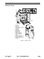
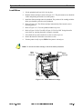
3ULQWHU2YHUYLHZ
1
2
3
14
4
5
6
7
8
9
10
13
11
12
1
2
3
4
5
6
7
8
9
0
1
2
3
4
5
6
7
8
9
Top Cover
Error LED
Power LED
Printhead Pressure Adjuster
Power Button
Feed Button
Printhead
Platen Roller
Media Guides
Media Hangers
Media Access Door
Battery Compartment
Media Compartment
Strap
Communications Port
Battery Charging Receptacle
Battery Charging LED
Charging Station Connector
Peel Bar
15
16
17
19
18
Figure 2-5. Printer Overview
/5HY
=HEUD3$37[6HULHV0DLQWHQDQFH0DQXDO
3DJH
6HFWLRQ
2SHUDWLRQ2YHUYLHZ
/RDG6XSSOLHV
Refer to Figure 2-5 for general printer assembly terminology and location for loading
supplies.
&DXWLRQ 'RQRWWRXFKWKHSULQWHOHPHQWVWKHSULQWKHDG'LUWDQGPRLVWXUHIURP\RXKDQGVFDQ
SUHPDWXUHO\VKRUWHQWKHSULQWKHDGOLIH
7HDU2II0RGH
3DJH
1.
Refer to Figure 2-6. Raise the media access door by lifting at the notch until it
unhooks from the top cover.
2.
Refer to Figure 2-7. Swing open the media access door to expose the media
compartment.
3.
Pivot the top cover up to reveal the printhead.
4.
Lift the printhead until you feel it lock in place. Do not force the printhead past this
position.
5.
Refer to Figure 2-8. Unroll approximately 6 in. (150 mm) of media. Thread the end
of the media into the printer, just below and behind the media hangers. Push the end
of the media into the printer until it extends approximately 1 in. (25 mm) beyond the
printhead.
6.
Separate and hold open the media hangers.
7.
Place the media roll onto the media hangers, ensuring it is tightly wound.
8.
Refer to Figure 2-7. Release the media hangers so the media locks into the correct
position. Ensure the media is threaded under both media guides.
9.
Refer to Figure 2-9. Install the tear blade into the media access door. Gently lift the
tab on the bar to get it over the door protrusion. Ensure the lip of the bar faces out.
10.
Close the printhead and the top cover.
11.
Refer to Figure 2-10. Swing up the media access door, ensuring that the media
extends over the tear blade.
12.
Lift to hook the top of the media access door over the top cover.
13.
Push in the bottom of the media access door to close.
14.
Turn the printer On (O) or press FEED if the printer is already on.
=HEUD3$37[6HULHV0DLQWHQDQFH0DQXDO
/5HY
2SHUDWLRQ2YHUYLHZ
6HFWLRQ
Top Cover
Notch
Media
Access
Door
Figure 2-6. Open Media Access Door
Media
Compartment
Printhead
Media
Guides
Media
Hangers
Figure 2-7. Raise Printhead Assembly
/5HY
=HEUD3$37[6HULHV0DLQWHQDQFH0DQXDO
3DJH
6HFWLRQ
2SHUDWLRQ2YHUYLHZ
Media
Guides
1 in. (25 mm) beyond
printhead
Media
Hangers
Unwind this direction
Media
Roll
Figure 2-8. Load Media
Tab
Protrusion
Lip
Figure 2-9. Install/Remove Tear Blade
3DJH
=HEUD3$37[6HULHV0DLQWHQDQFH0DQXDO
/5HY
2SHUDWLRQ2YHUYLHZ
6HFWLRQ
Tear Blade
Figure 2-10. Media Over Tear Blade
&DXWLRQ 'RQRWWRXFKWKHSULQWHOHPHQWVWKHSULQWKHDG'LUWDQGPRLVWXUHIURP\RXKDQGVFDQ
SUHPDWXUHO\VKRUWHQWKHSULQWKHDGOLIH
3HHO2II0RGH
/5HY
1.
Refer to Figure 2-6. Raise the media access door by lifting at the notch until it
unhooks from the top cover.
2.
Refer to Figure 2-7. Swing open the medis access door to expose the media
compartment.
3.
Pivot the top cover to reveal the printhead.
4.
Lift the printhead until you feel it lock in place. Do not force the printhead past this
position.
5.
Refer to Figure 2-8. Unroll approximately 6 in. (150 mm) of media. Remove and
discard the first label. Thread the end of the media into the printer, just below and
behind the media hangers. Push the end of the media into the printer until it extends
approximately 1 in. (25 mm) beyond the printhead.
6.
Separate and hold open the media hangers,
7.
Place the media roll onto the media hangers.
8.
Refer to Figure 2-7. Release the media hangers so the media locks into the correct
position. Ensure the media is threaded under both media guides.
9.
Refer to Figure 2-9. The tear blade should not be installed in the printer. To remove
the tear blade, gently lift the tab on the bar to get it over the door protrusion. Pull the
tear blade out of the printer.
=HEUD3$37[6HULHV0DLQWHQDQFH0DQXDO
3DJH
6HFWLRQ
2SHUDWLRQ2YHUYLHZ
Refer to Figure 2-11. The tear blade should be stored on the inside of the media access
door. With the lip of the tear blade facing the inside of the door, place the notches of the
tear blade over the tabs on the door. Press and slide the tear blade toward the hinged end.
Lift the tab to allow the tear blade to slip past the protrusion and lock in place.
10. Close the printhead and the top cover.
11.
Swing up the media access door, ensuring that the media liner is threaded through
the bottom slot in the media access door.
12.
Lift to hook the top of the media access door over the top cover.
13.
Push in the bottom of the media access door to close.
Door
Tab
Door
Tab
Tear Blade
Notch
Tear Blade
Notch
Figure 2-11. Store Tear Blade
Label
Liner
Bottom Slot
Figure 2-12. Thread Liner Peel-Off Mode
3DJH
=HEUD3$37[6HULHV0DLQWHQDQFH0DQXDO
/5HY
2SHUDWLRQ2YHUYLHZ
6HFWLRQ
/RDG5LEERQ
1.
Lift the printhead until you feel it lock in place.
2.
Hold the ribbon cartridge as shown in Figure 2-13. The placement arrows should be
visible and pointing toward the rear of the printer.
3.
Install the ribbon cartridge onto the printhead. The portion of the cartridge with the
white gear should be placed over the printhead.
4.
Refer to Figure 2-14. The ribbon cartridge automatically slides into the correct
operating position.
5.
Refer to Figure 2-15. Close the printhead and the top cover.
6.
Refer to Figure 2-10 for Tear-Off or Figure 2-12 for Peel-Off. Swing the media
access door up, ensuring the media is properly extended.
7.
Lift to hook the top of the media access door over the top cover.
8.
Push in the bottom of the media access door to close.
9.
Turn the printer On (O) or press FEED if the printer is already on.
1RWH7RUHPRYHWKHULEERQFDUWULGJHUHYHUVHWKHDERYHSURFHGXUHV
White
Gear
Arrows
Printhead
Ribbon
Cartridge
Figure 2-13. Insert Ribbon Cartridge
/5HY
=HEUD3$37[6HULHV0DLQWHQDQFH0DQXDO
3DJH
6HFWLRQ
2SHUDWLRQ2YHUYLHZ
Ribbon
Cartridge
Printhead
Figure 2-14. Operate Position (Ribbon Cartridge)
Close
Printhead
Ribbon
Figure 2-15. Close Printhead and Cover
3DJH
=HEUD3$37[6HULHV0DLQWHQDQFH0DQXDO
/5HY
2SHUDWLRQ2YHUYLHZ
6HFWLRQ
,QLWLDO3RZHU8S
3ULQW7HVW/DEHO
Before connecting the printer to a computer or portable data terminal, ensure it is in proper
working order. Print a configuration label by following the instructions in Table 2-1. A
sample configuration label is shown in Figure 2-16.
Figure 2-16. Sample Configuration Label
Figure 2-17. Sample ASCII/Hex Data Received Label
/5HY
=HEUD3$37[6HULHV0DLQWHQDQFH0DQXDO
3DJH
6HFWLRQ
2SHUDWLRQ2YHUYLHZ
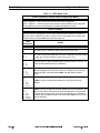
7DEOH)(('0RGH&KDUW
3RZHU2II0RGH&RPPXQLFDWLRQV'LDJQRVWLFV0RGH
:LWKWKHSULQWHU2II2SUHVVDQGKROG)(('ZKLOH\RXWXUQWKHSULQWHU2QO
5HIHUWR)LJXUH 7KHSULQWHUSULQWVRXWDOLVWRILWVFXUUHQWFRQILJXUDWLRQ
5HIHUWR)LJXUH $IWHUSULQWLQJWKHODEHOWKHSULQWHUZLOODXWRPDWLFDOO\HQWHUDGLDJQRVWLF
PRGHDQGSULQWVRXWDOLWHUDOUHSUHVHQWDWLRQRIDOOGDWDVXEVHTXHQWO\UHFHLYHG
3RZHU2Q0RGHV
:LWKWKHSULQWHU2QOSULQWKHDGFORVHGDQG(UURU/('RIISUHVVDQGKROG)(('IRUVHYHUDO
VHFRQGV7KH(UURU/('EHJLQVDVHULHVRIIODVKVHTXHQFHV(DFKVHTXHQFHFRQVLVWVRID
GLIIHUHQWQXPEHURIIODVKHVDVVKRZQLQWKHWDEOH7KHFRUUHVSRQGLQJDFWLRQLQGLFDWHVZKDW
KDSSHQVZKHQ\RXUHOHDVH)(('DIWHUHDFKIODVKVHTXHQFH
)ODVK
6HTXHQFH
3DJH
$FWLRQ
$FRQILJXUDWLRQODEHOSULQWV
7KHPHGLDVHQVRULVFDOLEUDWLQJDQGDPHGLDVHQVRUSURILOHSULQWV
7KHVHULDOFRPPXQLFDWLRQSDUDPHWHUVDUHUHVHWWREDXGELWZRUGOHQJWK
QRSDULW\DQGVWRSELWDQGIORZFRQWUROLVVHWWRXON/XOFF
5HVHWVWKHSULQWHUWRIDFWRU\GHIDXOWVDQGWKHYDOXHVDUHVDYHGLQPHPRU\7KH
SULQWHUDOVRDXWRPDWLFDOO\SHUIRUPVDFDOLEUDWLRQ
7KHSULQWZLGWKLVFDOLEUDWLQJ:KLOHWKH(UURU/('IODVKHVUDSLGO\DVHULHVRI
VWDFNLQJUHFWDQJOHSULQWVRQWKHODEHO:KHQWKHUHFWDQJOHSULQWVWRWKHRXWHU
HGJHVRIWKHODEHOSUHVVDQGUHOHDVH)(('7KHODEHOZLGWKLVVDYHGLQ
PHPRU\
,I)(('LVKHOGIRUVL[IODVKHVDQGUHOHDVHGWKHSULQWHULJQRUHVLWZKHQ
UHOHDVHG
,I)(('LVKHOGIRUVL[IODVKHVDQGKHOGDQDGGLWLRQDOILYHVHFRQGVDIWHUWKHVL[WK
IODVKWKH/('IODVKHVDVHYHQWKWLPH:KHQUHOHDVHGDIWHUWKHVHYHQWKIODVK
WKHULEERQVHQVRUERDUG37[VHULHVRQO\ZLOOFDOLEUDWH2QFHFDOLEUDWLRQLV
FRPSOHWHGWKH/('IODVKHVUDSLGO\3UHVVDQGUHOHDVH)(('RQHPRUHWLPHWR
VDYHWKHFDOLEUDWLRQ
=HEUD3$37[6HULHV0DLQWHQDQFH0DQXDO
/5HY
2SHUDWLRQ2YHUYLHZ
6HFWLRQ
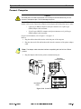
&RQQHFW&RPSXWHU
&DXWLRQ
7KH5-MDFNRQWKHVLGHRIWKHSULQWHULVIRUVHULDOSRUWFRPPXQLFDWLRQVRQO\'RQRW
FRQQHFWWRDWHOHSKRQHMDFN7KLVZLOOGDPDJHWKHSULQWHU
The PA/PT40x Series printer is configured as Data Terminal Equipment (DTE). The null
modem cable used to connect the computer to the adapter cable and printer may be either:
•
9-pin D-type (DB9S) computer serial port connector to a 9-pin D-type
(DB9P) adapter cable connector.
•
25-pin D-type (DB25S) computer serial port connector to a 9-pin D-type
(DB9P) adapter cable connector.
For pin out information, refer to Figure 1-2 on page 1-4.
Refer to .
1. Plug the null modem cable into the serial data port of the computer.
2.
Plug the other end of the null modem cable into the connector of the printer adapter
cable.
1RWH7KHDGDSWHUFDEOHPDLQWDLQVLQWHUIDFHFRPSDWLELOLW\ZLWKWKHIXOOOLQHRI=HEUD
SULQWHUV
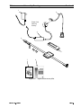
3.
Plug the adapter cable into the printers communication port.
Computer
Communications
Ports
Adapter
Cable
10101
10101
10101
10101
Null Modem
Cable
Figure 2-18. Serial Cable Hookup
/5HY
=HEUD3$37[6HULHV0DLQWHQDQFH0DQXDO
3DJH
6HFWLRQ
2SHUDWLRQ2YHUYLHZ
6HW&RPPXQLFDWLRQ3DUDPHWHUV
When using the printer’s serial port to transfer data, the printer and the computer must
have identical communication parameter settings.
'HIDXOWYDOXHV
Press and hold FEED until the Error LED flashes once, twice, and then three times.
Release FEED after the LED flashes three times. The baud rate for the printer resets to
9600 baud, 8-bit word length, no parity, 1 stop bit, and the flow control sets to XON/
XOFF. The computer’s communication parameters now need to match the default settings
of the printer. Refer to Table 2-1 for a complete listing of Feed Modes.
&XVWRPYDOXHV
If settings different from the default values are needed, send the set communications
(^SC) ZPL command at 9600 baud via the serial port setup, then reset the computer to the
new values (see the ZPL II Programming Guide for the complete command syntax). To
save the settings permanently, send the ^JUs ZPL II command or recalibrate the printer.
&DOLEUDWH
The printer’s media sensor sensitivity establishes how your printer detects the top of the
label. If you are using die-cut label media, the printer needs to detect the difference
between no media in the printer at all, liner only (indicating the space/gap between labels),
and a label plus liner.
To make these distinctions, the printer shines light through the media and measures the
amount of light making it through the media. In this way, the printer can detect where your
labels begin and end, and when you run out of media.
$PRXQWRIOLJKW
GHWHFWHG
+LJK
:KDWLWLVGHWHFWLQJ
1RWKLQJ1RPHGLDLVSUHVHQW
0HGLXP
0HGLDOLQHURQO\
/RZ
/DEHOSOXVOLQHU
:KDWLWPHDQV
2XWRIPHGLDRUWKHQRWFKJDSEHWZHHQ
ODEHOVLI\RXDUHXVLQJQRWFKHGPHGLD
RUWDJVWRFN
7KHZHEEHWZHHQODEHOVLVGLUHFWO\
XQGHUWKHVHQVRU
$ODEHOLVGLUHFWO\XQGHUWKHVHQVRU
1RWH,I\RXDUHXVLQJQRWFKHGPHGLDRUWDJVWRFNWKHYDOXHVIRU+LJKDQG0HGLXPZLOO
EHLGHQWLFDO7KLVLVEHFDXVHWKHVSDFHEHWZHHQWDJVLVLQGLFDWHGE\DQRWFKRUJDSLQ
WKHPHGLDLQVWHDGRIE\WKHZHEEHWZHHQODEHOV
3DJH
=HEUD3$37[6HULHV0DLQWHQDQFH0DQXDO
/5HY
2SHUDWLRQ2YHUYLHZ
6HFWLRQ
$XWR&DOLEUDWLRQ
1RWH7KHSULQWHUGRHVQRWDXWRFDOLEUDWHFRUUHFWO\ZKHQ\RXDUHXVLQJSUHSULQWHG
ODEHOV,IWKLVW\SHRIPHGLDLVEHLQJXVHGVHH0DQXDO&DOLEUDWLRQRQSDJH By default, this printer automatically sets the sensor levels and determines the length of
the label being used. To auto-calibrate:
1. Turn the printer On (O).
2.
Load the media and close the printhead.
3.
Press FEED. Two labels print, completing auto-calibration.
Auto-calibration works only when you are using non-continuous media (a gap or notch
separates each label).
Auto-calibration is performed when the printer is turned On (O) (if the printhead has been
opened) and whenever an error is cleared.
1RWH5HIHUWR7DEOH 3HUIRUPLQJDPDQXDOFDOLEUDWLRQGLVDEOHVWKHDXWR
FDOLEUDWLRQIXQFWLRQ7RUHWXUQWRDXWRFDOLEUDWLRQHLWKHUGHIDXOWWKHSULQWHURUUHIHUWR
\RXUODEHOSUHSDUDWLRQVRIWZDUHXVHUVJXLGH
1RWH:KHQXVLQJEODFNPDUNRUZHEODEHOVVHWWKHDSSURSULDWHVRIWZDUHFRPPDQG
VHH\RXUODEHOSUHSDUDWLRQVRIWZDUHXVHUVJXLGHEHIRUHSHUIRUPLQJDPDQXDO
FDOLEUDWLRQ
0DQXDO&DOLEUDWLRQ
Perform manual calibration whenever preprinted labels are being used or if the printer
does not auto-calibrate. To calibrate manually:
1. Turn the printer On (O).
/5HY
2.
Remove several labels from a section of the liner to thread the liner only through the
printer.
3.
Press and hold FEED until the Error LED flashes once, then twice. Release FEED.
Refer to Table 2-1 for a complete listing of Feed Modes.
4.
The printer sets the media sensor for the liner being used. After it makes this
adjustment, the roll automatically feeds until a label is positioned at the printhead.
5.
Refer to Figure 2-19. A profile of the media sensor setting prints. Upon completion,
the printer saves the new settings in memory and the printer is ready for normal
operations.
=HEUD3$37[6HULHV0DLQWHQDQFH0DQXDO
3DJH
6HFWLRQ
2SHUDWLRQ2YHUYLHZ
&DOLEUDWH5LEERQ6HQVRU
37[RQO\
Perform this ribbon sensor calibration whenever a new Ribbon Sensor Board is installed.
To calibrate the ribbon sensor:
1. Turn printer Off (2).
2.
Install an empty ribbon cartridge with a white core into the PT400.
3.
Turn the printer On (O.
4.
Press and hold FEED.
5.
The Error LED begins to flash. When the LED flashes for the sixth time, continue to
hold (for an additional five seconds) until the seventh flash. Release FEED after the
seventh flash.
6.
When the ribbon sensor calibration is complete, the Error LED flashes rapidly. Press
and release FEED one more time to save the calibration.
7.
Remove the empty ribbon cartridge and reload with a ribbon cartridge containing
ribbon.
Figure 2-19. Sample Media Profile
6HWXS6RIWZDUH
To create labels, you must decide whether you will use ZPL II or commercial label
preparation software. To use ZPL II, refer to the ZPL II Programming Guide (Zebra part
number 46469L). If you choose to use a commercial label preparation software, follow the
installation instructions included in the package.
3DJH
=HEUD3$37[6HULHV0DLQWHQDQFH0DQXDO
/5HY
2SHUDWLRQ2YHUYLHZ
6HFWLRQ
2SHUDWH3ULQWHU
To create a label for the Zebra PA400, you may either use a commercial label preparation
system software, such as Zebra BAR-ONE, to create the label format or write one in
ZPL II, which is Zebra’s programming language for creating labels. If you are using
commercial label preparation software, refer to the software’s help files or users guide. If
you are using ZPL II to format your labels, ensure that you have a copy of the ZPL II
Programming Guide (Zebra part number 46469L).
$GMXVW'DUNQHVV
If using commercial label preparation software, adjust the relative darkness setting as
indicated by the software manufacturer. If ZPL II is being used, send the ^MD (Media
Darkness) or ~SD (Set Darkness) command (see the ZPL II Programming Guide for the
complete command syntax).
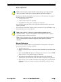
$GMXVW3ULQWKHDG3UHVVXUH
Printhead pressure needs to be adjusted if print darkness is inconsistent across the label, if
thick or thin label stock is being used, or if the registration of narrow media is a problem.
1RWH6OLGLQJWKHSULQWKHDGSUHVVXUHDGMXVWHUWRZDUGWKHEDFNRIWKHSULQWHULQFUHDVHV
WKHSUHVVXUH6OLGLQJLWWRZDUGWKHIURQWRIWKHSULQWHUGHFUHDVHVWKHSUHVVXUH
If the labels darkness is uneven or the image distorted:
1. Refer to Figure 2-20. Slide the printhead pressure adjuster toward the rear of the
printer until it stops at the next setting.
2.
Print another test label. If the image remains irregular, repeat step 1.
If the printing on the label is too dark, reverse the above procedures.
Printhead
Pressure
Adjust
Darkest
Pressure
Setting
Lightest
Pressure
Setting
Do not adjust these screws!
Figure 2-20. Printhead Pressure Adjustment
/5HY
=HEUD3$37[6HULHV0DLQWHQDQFH0DQXDO
3DJH
6HFWLRQ
2SHUDWLRQ2YHUYLHZ
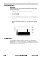
$GMXVW)DVWVWUDS
&RQYHUWWRD6KRXOGHU6WUDS
1.
Refer to Figure 2-21. With the front of the printer facing you, unwrap the padded
handle by lifting up the loose end of the handle.
2.
Unlatch the buckle by squeezing both sides of the fastener.
3.
Pull up the padded handle.
4.
Wrap and secure the padded handle around the strap.
1
4
Handle
2
(Pull Up)
Fastener
Buckle
3
Figure 2-21. Convert to a Shoulder Strap
3DJH
=HEUD3$37[6HULHV0DLQWHQDQFH0DQXDO
/5HY
2SHUDWLRQ2YHUYLHZ
6HFWLRQ
&RQYHUWWRD+DQG6WUDS
1.
Refer to Figure 2-22. With the front of the printer facing you, unwrap the padded
handle by lifting up the loose end of the handle.
2.
Pull the buckle to the right until the strap is taut.
3.
Latch the buckle by inserting the fastener into the buckle.
4.
Wrap and secure the padded handle around the strap.
2
3
Handle
Fastener
Buckle
2
1
Figure 2-22. Convert to a Hand Strap
/5HY
=HEUD3$37[6HULHV0DLQWHQDQFH0DQXDO
3DJH
6HFWLRQ
3DJH
2SHUDWLRQ2YHUYLHZ
=HEUD3$37[6HULHV0DLQWHQDQFH0DQXDO
/5HY
7URXEOHVKRRWLQJ
6HFWLRQ
6HFWLRQ
7URXEOHVKRRWLQJ
Use Table 3-1 to match your printer’s LED status to the chart. The last column of
Table 3-1 gives a number to refer to in Table 3-2 on page 3-2. Table 3-3 on page 3-3 lists
print quality problems that may or may not have any trouble indication from the LEDs.
Tables 3-2 and 3-3 Troubleshooting Charts list the most common problems that may be
encountered when operating the PA/PT40x printer.
7URXEOHVKRRW
/('V
7DEOH/('7URXEOHVKRRWLQJ&KDUW
/('6WDWXV
/5HY
,VWKHSULQWHU
SDXVHG"
2Q7DEOH
UHIHUWR
2II
<HV
)ODVKLQJ
2Q
<HV
'RXEOH)ODVKLQJ
2Q
<HV
2Q
2Q
1R
2Q
2Q
<HV
2II
)ODVKLQJ
1R
$OWHUQDWH)ODVKLQJ
<HV
6LPXOWDQHRXV)ODVKLQJ
<HV
DQG
2Q
)ODVKLQJ
1R
DQG
2Q
)ODVKLQJ
<HV
DQG
'RXEOH)ODVKLQJ
)ODVKLQJ
<HV
DQG
(UURU/('
2UDQJH
3RZHU/('
*UHHQ
2II
3DJH
7URXEOHVKRRWLQJ
6HFWLRQ
7DEOH/('7URXEOHVKRRWLQJ5HVROXWLRQ&KDUW
'LDJQRVLV
$FWLRQ
3UHVV2QO
3ULQWHULVQRWUHFHLYLQJSRZHU
(QVXUHWKHEDWWHU\LVIXOO\FKDUJHGDQGSURSHUO\
LQVWDOOHG7U\DQRWKHUIXOO\FKDUJHGEDWWHU\
0HPEUDQHVZLWFKGHIHFWLYH
3RZHUVXSSO\ERDUGGHIHFWLYH
0DLQORJLFERDUGGHIHFWLYH
3ULQWKHDGLVRSHQ
&ORVHWKHWRSFRYHUDQGPHGLDDFFHVVGRRU
0HGLDLVRXW
/RDGDUROORIPHGLD
3ULQWHULVSDXVHG
3UHVV)(('WRUHVXPHSULQWLQJ
3ULQWKHDGLVXQGHUWHPSHUDWXUH
&RQWLQXHSULQWLQJZKLOHWKHSULQWKHDGUHDFKHVWKH
FRUUHFWRSHUDWLQJWHPSHUDWXUH
3ULQWKHDGLVRYHUWHPSHUDWXUH
%DWWHU\LVRYHUWHPSHUDWXUH
%DWWHU\LVXQGHUYROWDJHOHYHO
/5HY
3ULQWLQJDXWRPDWLFDOO\VWRSVXQWLOWKHSULQWKHDGRU
EDWWHU\UHWXUQVWRDQDFFHSWDEOHSULQWLQJ
WHPSHUDWXUH
:DLWXQWLOWKHFXUUHQWODEHOILQLVKHVSULQWLQJWKHQ
SOXJWKHEDWWHU\FKDUJHULQWRWKHSULQWHU
<RXGRQRWKDYHWRWXUQWKHSULQWHURIILQRUGHUWR
GRWKLV
%DWWHU\LVXQGHUYROWDJHOHYHO
7KHEDWWHU\PD\QRWKDYHHQRXJKSRZHUWRSULQWWKH
QH[WODEHODQGPD\UHVHWWKHSULQWHUORVLQJIRUPDWV
LQWKHSULQWHU3OXJWKHEDWWHU\FKDUJHULQWRWKH
SULQWHU$IWHUWKHEDWWHU\LVFKDUJHGSUHVV)(('
)ODVKPHPRU\LVQRWSURJUDPPHG
)ODVKPHPRU\QHHGVWREHUHSURJUDPPHGRU
PHPRU\ERDUGQHHGVWREHUHSODFHG
3DJH
6HFWLRQ
7URXEOHVKRRWLQJ
7DEOH3ULQW4XDOLW\&KDUW
'LDJQRVLV
$FWLRQ
(QVXUHWKDWGLUHFWWKHUPDOPHGLDLVORDGHGLQWRWKHSULQWHU
1RSULQWRQWKHODEHO
(QVXUHWKHPHGLDLVORDGHGFRUUHFWO\
(QVXUHWKHSULQWHULVEHLQJXVHGZLWKLQRSHUDWLRQDOOLPLWVRI
EHWZHHQ°)DQG°)°&DQG°&
3ULQWGDUNQHVVQHHGVWREHDGMXVWHG
3ULQWKHDGLVGLUW\&OHDQWKHSULQWKHDG
3ULQWKHDGSUHVVXUHQHHGVWREHDGMXVWHG
3ULQWHGLPDJHGRHVQRWORRN
7KHPHGLDEHLQJXVHGLVLQFRPSDWLEOHZLWKWKHSULQWHU%HVXUH
ULJKW
WRXVH=HEUDUHFRPPHQGHGPHGLDIRU\RXUDSSOLFDWLRQ
%DWWHU\YROWDJHLVORZ&KDUJHRUUHSODFHEDWWHU\
3ULQWKHDGGHIHFWLYH5HSODFHSULQWKHDG
/RQJWUDFNVRIPLVVLQJSULQW 3ULQWKHDGLVGLUW\&OHDQWKHSULQWKHDG
EODQNYHUWLFDOOLQHVRQ
3ULQWHOHPHQWLVGDPDJHG5HSODFHWKHSULQWKHDG
VHYHUDOODEHOV
0HGLDPD\QRWEHWKUHDGHGXQGHUWKHPHGLDJXLGHV
3ULQWKHDGSUHVVXUHQHHGVWREHDGMXVWHG
0LVUHJLVWUDWLRQRIODEHOV
SULQWLQJGRHVQRWVWDUWDWWKH 3ULQWHUQHHGVWREHUHFDOLEUDWHG
WRSRIWKHODEHODQGPLVSULQW
7KHFRUUHFWPHGLDVHQVRUPD\QRWEHDFWLYDWHG,QPDQXDO
RIRQHWRWKUHHODEHOV
FDOLEUDWLRQVHOHFWWKHPHGLDVHQVLQJPHWKRGIRUWKHODEHOV\RX
DUHXVLQJUHIHUWR\RXUODEHOSUHSDUDWLRQVRIWZDUHXHUVJXLGH
(QVXUHWKHSULQWHUZDVQRWLQ3DXVH0RGH
7KHFRPPXQLFDWLRQSDUDPHWHUVDUHLQFRUUHFW(QVXUHWKH
FRUUHFWFRPPXQLFDWLRQSRUWVRQWKHFRPSXWHUDUHVHOHFWHG
9HULI\WKHSULQWHUDQGFRPSXWHUDUHXVLQJWKHVDPHKDQGVKDNH
$ODEHOIRUPDWZDVVHQWEXW
(QVXUHWKHEDXGUDWHVRIWKHSULQWHUDQGFRPSXWHUPDWFK
QRWUHFRJQL]HGE\WKH
SULQWHU
(QVXUHGDWDFDEOHLVDQXOOPRGHPFDEOHDQGLQVWDOOHGFRUUHFWO\
5HSODFHLIGHIHFWLYH
3ULQWHURUFRPSXWHUVHULDOSRUWVDUHGHIHFWLYH
,I/('VDUHRQRUIODVKLQJFKHFN7DEOH RQSDJH 3DJH
/5HY
7URXEOHVKRRWLQJ
6HFWLRQ
)DFWRU\$VVLVWDQFH
Should you encounter any problem that cannot be corrected with the aid of this manual,
and you have Internet access, check out ZIP Support at http://support.zebra.com. If you
cannot solve your problem via ZIP Support or do not have Internet access, contact your
Distributor or Zebra Technologies’ Technical Support Department to minimize or avoid
printer downtime.
=,36XSSRUW
•
Questions can be identified, diagnosed, and resolved all in one brief, easy,
on-line session.
•
ZIP Support is updated regularly by Zebra corporate product experts,
guaranteeing the most comprehensive, timely product information available.
•
High-speed, accurate, intuitive database utilizes text and graphics.
•
Available any time, all time zones, 24 hours a day, 365 days a year
7HFKQLFDO6XSSRUW
Zebra Technologies
Mobile Printer Center of Excellence
Phone:
+1 401.739.5900
Fax:
+1 401.732.0808
Email
[email protected]
Zebra Technologies Europe Limited, UK
Phone:
Fax:
Email
+44 (0) 1494 7682984
+44 (0) 1494 768210
[email protected]
5HSDLU6HUYLFH'HSDUWPHQW
For in factory service and repair.
Zebra Technologies
Mobile Printer Center of Excellence
Phone:
+1 401.739.5900
Fax:
+1 401.732.0808
Zebra Technologies Europe Limited, UK
Phone:
Fax:
+44 (0) 1494 7682984
+44 (0) 1494 768210
50$
5HTXHVW
XNUPD#]HEUDFRP
5HWXUQLQJ(TXLSPHQW
A Return Materials Authorization (RMA) number is required for all equipment being
returned. Contact Zebra Technologies’ Technical Support Department to obtain an RMA
number. Equipment returned for service without prior authorization may be refused.
Whenever possible, use the original shipping container. Should it become necessary to
ship your printer, carefully pack the printer in a suitable container to avoid damage during
transit. Enclose a note describing the failure with the unit. Replacement shipping
containers can be ordered by contacting Zebra Technologies’ Technical Support
Department.
If other containers are used, be sure to use packaging material similar to the original
factory packaging. Remove all media from the printer. Enclose the unit in a protective,
dustproof bag and ensure the unit floats in an outer carton of shock-absorbing material.
/5HY
3DJH
0DLQWHQDQFH
6HFWLRQ
6HFWLRQ
0DLQWHQDQFH
7DEOHRI&RQWHQWV
Preventive Maintenance Schedule ...................................................................... 4-5
Clean ................................................................................................................... 4-5
Battery Maintenance ........................................................................................... 4-6
Lubrication .......................................................................................................... 4-6
Corrective Maintenance ...................................................................................... 4-7
Tools Required .................................................................................................... 4-7
Part and Assembly Identification ........................................................................ 4-7
Remove/Install Shoulder Strap ........................................................................... 4-8
Remove Shoulder Strap ...................................................................................... 4-8
Install Shoulder Strap .......................................................................................... 4-8
Disassemble/Assemble Printer ........................................................................... 4-9
Disassemble Printer ............................................................................................ 4-9
Reassemble Printer ........................................................................................... 4-11
Route Battery Access Door Replace ................................................................. 4-12
Replace Main Logic Board ............................................................................... 4-13
Replace Power Supply Board ........................................................................... 4-15
Replace Printhead Assembly ............................................................................ 4-17
Replace Ribbon Sensor Board Assembly ......................................................... 4-19
Replace Print Mechanism Module .................................................................... 4-22
Replace Wiring Harness ................................................................................... 4-23
Replace Membrane Switch Assembly .............................................................. 4-26
Repair Media Guide .......................................................................................... 4-28
IrDA Board and Cable Replacement ................................................................ 4-30
/5HY
3DJH
0DLQWHQDQFH
6HFWLRQ
(TXLSPHQW6DIHW\7LSV
R
R
After reviewing each procedure, place a check in the box.
The AC power plug and IEC 320 connectors on all Zebra printers must bear the
certification mark of at least one international safety organization listed below.
+
R
R
R
R
R
/5HY
Unless indicated otherwise, turn the power Off (2) before performing any
maintenance procedures to the printer.
Always follow proper electrostatic safety precautions when removing, handling,
and replacing all printed circuit boards and integrated circuits.
Zebra printers comply with international regulations governing radiated emissions
when using fully shielded data cables. Data cables must be fully shielded and
fitted with metal or metalized connector shells. Required Shielded data cables and
connectors prevent radiation and reception of electrical noise. Use of unshielded
data cables may increase radiated emissions above the regulated limits.
Avoid direct contact with the printhead elements. Dirt and moisture from the skin
can cause corrosion and prematurely shorten the printhead life.
3DJH
6HFWLRQ
0DLQWHQDQFH
(TXLSPHQW6DIHW\7LSV&RQWLQXHG
R
R
R
R
R
R
3DJH
To ensure optimum printhead life, observe proper electrostatic safety precautions
(for example ESD wrist straps) when removing, handling, and replacing the
printhead.
Nickel Cadmium (Ni-Cd) must be recycled or disposed of properly. They must
not be disposed of in municipal waste. For recycling information in the United
States and Canada, please call 1-800-8-BATTERY.
Zebra recommends using solvent containing 90% isopropyl alcohol, 10% distilled
water for cleaning:
•
Printheads
•
Peel-Off edge
•
Platen rollers
•
Media path
•
Tear blade
Ribbons used in thermal transfer printers must be as wide as or wider than the
media. If the ribbon is narrower than the media, areas of the printhead will be
unprotected and subject to premature wear.
Avoid dropping or banging the printer.
Avoid direct contact with the printhead elements. Injury can occur if elements are
hot.
/5HY
0DLQWHQDQFH
6HFWLRQ
3HUVRQDO6DIHW\7LSV
R
R
R
R
R
/5HY
Danger of an explosion exists if the Ni-Cd battery is discharged incorrectly.
Do not wear any jewelry (rings, watches, etc.) or loose clothing when servicing
the printers.
Beware of pinch points on the printers. Be especially careful of:
•
Opening and closing covers
•
Printhead
•
Platen roller
Wear protective eyewear when removing E-rings, C-clips, and springs.
For personal and equipment safety, use only Zebra-supplied and-approved battery
chargers and power supplies.
3DJH
0DLQWHQDQFH
6HFWLRQ
3UHYHQWLYH0DLQWHQDQFH6FKHGXOH
&OHDQ
&DXWLRQ 'RQRWWRXFKWKHSULQWHOHPHQWVRQWKHSULQWKHDG'LUWDQGPRLVWXUHIURPKDQGVFDQ
SUHPDWXUHO\VKRUWHQSULQWKHDGVOLIH
7DEOH&OHDQ6FKHGXOH
$UHD
0HWKRG
,QWHUYDO
1RWH<RXGRQRWQHHGWRWXUQWKHSULQWHURIISULRUWRFOHDQLQJWKH3ULQWKHDG
3ULQWKHDG
8VHLVRSURS\ODOFRKRORQDFRWWRQVZDEWRFOHDQWKH
SULQWHOHPHQWVIURPHQGWRHQG7KHSULQWHOHPHQWVDUHWKH
WKLQZLUHVRQWKHSULQWKHDG
3ODWHQ5ROOHU
:LWKWKHSRZHUWXUQHGRIIURWDWHWKHSODWHQUROOHUDQGFOHDQLW
WKRURXJKO\ZLWKLVRSURS\ODOFRKRODQGDFRWWRQVZDE
3HHO%DU
2SHQWKHPHGLDDFFHVVGRRUDQGWKRURXJKO\FOHDQWKH
SHHORIIHGJHZLWKLVRSURS\ODOFRKRORQDFOHDQOLQWIUHH
FORWK
7HDU%ODGH
&OHDQLWWKRURXJKO\ZLWKLVRSURS\ODOFRKRODQGDFRWWRQ
VZDE
$IWHUHYHU\
ILYHUROOVRI
PHGLD
$VQHHGHG
1RWH'RQRWDGMXVWRUUHPRYHWKHWZRVFUHZVRQWKHSULQWKHDG
+HDG2SHQ
6HQVRU
/5HY
8VHLVRSURS\ODOFRKRORQDFRWWRQVZDEWRFOHDQXQGHU
WKHVFUHZRQWKHSULQWKHDGKHDGRSHQVHQVRUDVVKRZQLQ $VQHHGHG
)LJXUH
([WHULRU
:DWHUGDPSHQHGUDJ
$VQHHGHG
,QWHULRU
%UXVKDLUEORZ
$VQHHGHG
3DJH
6HFWLRQ
0DLQWHQDQFH
%DWWHU\0DLQWHQDQFH
Check battery contacts and keep clean of corrosion and grime. Clean contacts with 90%
isopropyl alcohol and a cotton swab.
Batteries should be completely discharged once per week. To discharge, run the printer
until you get a battery under voltage—level 1 indication (Error LED off and Power LED
flashing). Follow the procedures in Charge Battery on page 2-3 for recharging the battery.
/XEULFDWLRQ
&DXWLRQ 1ROXEULFDWLQJDJHQWVRIDQ\NLQGVKRXOGEHXVHGRQWKLVSULQWHU6RPHFRPPHUFLDOO\
DYDLODEOHOXEULFDQWVZLOOGDPDJHWKHILQLVKDQGWKHPHFKDQLFDOSDUWV
Press
Down
Head-Open Sensor Plate
Clean under screw.
Figure 4-1. Clean Head-Open Sensor
3DJH
/5HY
0DLQWHQDQFH
6HFWLRQ
&RUUHFWLYH0DLQWHQDQFH
7RROV5HTXLUHG
3KLOOLSV6FUHZGULYHUV
$QWL6WDWLF0DW
)ODW%ODGH6FUHZGULYHULQ $QWL6WDWLF:ULVW6WUDS
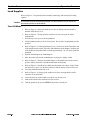
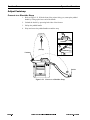
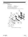
3DUWDQG$VVHPEO\,GHQWLILFDWLRQ
Use Figure 4-2 when identifying printer parts or assemblies for troubleshooting.
Printer
Front
Cover
Power
Supply
Board
Rubber
Bezel
Print
Mechanism
Module
Shoulder
Strap
Sleeve
Printer
Rear
Cover
Battery
Access
Door
Shoulder
Strap
Sleeve
Main
Logic
Board
Figure 4-2. Identify Parts and Assemblies
/5HY
3DJH
6HFWLRQ
0DLQWHQDQFH
5HPRYH,QVWDOO6KRXOGHU6WUDS
5HPRYH6KRXOGHU6WUDS
1.
Turn the printer Off (2). Disconnect the battery charger.
2.
Lay the printer on a flat surface with the back of the printer facing up.
3.
Remove the two shoulder strap screws indicated in Figure 4-3.
4.
Remove the shoulder strap.
1RWH,IWKHVKRXOGHUVWUDSLVQRWWREHUHSODFHGRUUHLQVWDOOHGRQWKHSULQWHUWKH
VKRXOGHUVWUDSVOHHYHVPXVWEHUHPRYHGIURPWKHVWUDSORRSV3XWWKHVKRXOGHUVWUDS
VOHHYHVEDFNEHWZHHQWKHSULQWHUFRYHUVDQGUHLQVWDOOWKHVFUHZV
,QVWDOO6KRXOGHU6WUDS
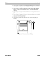
1.
Turn the printer Off (2). Disconnect the battery charger.
2.
Lay the printer on a flat surface with the back of the printer facing upwards.
3.
Remove the two shoulder strap screws indicated in Figure 4-3.
4.
Slide one shoulder strap sleeve into each of the loops at both ends of the shoulder
strap.
5.
Slide the buckle end of the shoulder strap, with the shoulder strap sleeve inserted,
between the front and rear cover where you removed the right shoulder strap screw
(facing the rear of printer). Replace the screw.
6.
Slide the other end of the shoulder strap, with the shoulder strap sleeve inserted,
between the front and rear cover where you removed the second screw. Replace the
screw.
7.
To adjust the strap length, follow the procedures in Adjust Faststrap on page 2-20.
Buckle
Shoulder
Strap
Sleeve
Shoulder
Strap
Sleeve
Shoulder
Strap
Screw
Shoulder
Strap
Screw
Figure 4-3. Remove/Install Shoulder Strap
3DJH
/5HY
0DLQWHQDQFH
6HFWLRQ
'LVDVVHPEOH$VVHPEOH3ULQWHU
&DXWLRQ
2EVHUYHSURSHUHOHFWURVWDWLFVDIHW\SUHFDXWLRQVZKHQUHPRYLQJKDQGOLQJDQGUHSODFLQJ
SULQWHGFLUFXLWERDUGV
'LVDVVHPEOH3ULQWHU
/5HY
1.
Turn the printer Off (2). Disconnect the battery charger.
2.
Slide the battery compartment door open and remove the battery.
3.
Lay the printer on a flat surface with the back of the printer facing up.
4.
Remove the two shoulder strap screws indicated in Figure 4-3. Place the shoulder
strap, two shoulder strap sleeves, and two shoulder strap screws to the side.
5.
Remove the five cover mounting screws.
6.
Lift the rear cover off and place it aside.
7.
Refer to Figure 4-4. Disconnect J2 (motor harness) and J1 (printhead harness) from
the power supply board.
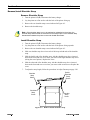
8.
Refer to Figure 4-5. Grab the print mechanism module by the access door top. Pivot
it upward (the bottom of the print mechanism module is still inside the printer front
cover) and lift straight up. Place the print mechanism module on the antistatic mat.
9.
Refer to Figures 4-4 and 4-5. Carefully lift the power supply board and main logic
board out enough to get access to J12 (membrane switch ribbon cable).
10.
Remove J12 (membrane switch ribbon cable).
11.
Place both boards on the antistatic mat.
12.
Refer to Figure 4-7. Lift the battery access door up and out of the front cover.
3DJH
6HFWLRQ
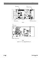
0DLQWHQDQFH
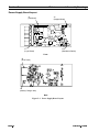
J1
(Printhead)
J2
(Stepper Motor)
J7
(Logic Board)
J12
(Membrane Switch)
Front
J5
(RJ45 Jack)
J9
(Battery Charger Jack)
Back
Figure 4-4. Power Supply Board Layout
3DJH
/5HY
0DLQWHQDQFH
6HFWLRQ
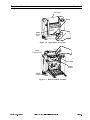
5HDVVHPEOH3ULQWHU
1.
Refer to Figure 4-4. Replace J12 (membrane switch ribbon cable).
2.
Ensure the contacts on the membrane switch ribbon cable face away from the edge
of the main logic board, where J12 is found. Reinstall the membrane switch ribbon
cable into J12.
3.
Refer to Figure 4-5. Slide the power supply board and main logic board into the
front cover, ensuring the rubber bezel slides into the slots in the front cover.
4.
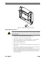
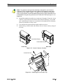
Refer to Figure 4-6. Place the print mechanism, with the media access door facing
down, into the front cover by holding it at the top by the access door. Slide the
bottom of the print mechanism into the front cover first.
5.
Refer to Figure 4-4 and replace J2 (motor harness) and J1 (printhead harness). J2
and J1 are keyed and will fit only one way. Do not force them into the connectors.
6.
Refer to Figure 4-12. Route all harnesses to avoid pinching and screw posts.
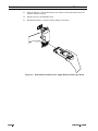
7.
Refer to Figure 4-7 on page 4-13. Ensure the battery access door is in the slot of the
front cover with the flat side facing in.
8.
Replace the cover and shoulder strap.
9.
Install a battery, load the media, and test the unit. Connect a battery charger if
necessary.
Figure 4-5. Remove/Install Power Supply Board and Main Logic Board
/5HY
3DJH
6HFWLRQ
0DLQWHQDQFH
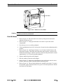
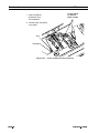
Figure 4-6. Remove/Install Print Mechanism Module
5RXWH%DWWHU\$FFHVV'RRU5HSODFH
3DJH
1.
Turn the printer Off (2). Disconnect the battery charger.
2.
Slide the battery compartment door open and remove the battery.
3.
Lay the printer on a flat surface with the back facing up.
4.
Remove the two shoulder strap screws indicated in Figure 4-3 on page 4-8. Set the
shoulder strap, two shoulder strap sleeves, and two shoulder strap screws aside.
5.
Remove the cover mounting screws.
6.
Lift the rear cover off and set it aside.
7.
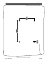
Refer to Figure 4-7. Lift the battery access door up and out of the front cover.
8.
Insert the new battery access door, ensuring it is in the slot of the front cover with
the flat side facing in.
9.
Refer to Figure 4-8. Ensure all harnesses are routed to avoid pinching and screw
posts.
10.
Replace the cover and shoulder strap.
11.
Install a battery, load the media, and test the unit. Connect a battery charger if
necessary.
/5HY
0DLQWHQDQFH
6HFWLRQ
Figure 4-7. Remove/Install Battery Access Door
5HSODFH0DLQ/RJLF%RDUG
&DXWLRQ
2EVHUYHSURSHUHOHFWURVWDWLFVDIHW\SUHFDXWLRQVZKHQUHPRYLQJKDQGOLQJDQGUHSODFLQJ
SULQWHGFLUFXLWERDUGV
/5HY
1.
Turn the printer Off (2). Disconnect the battery charger.
2.
Slide the battery compartment door open and remove the battery.
3.
Lay the printer on a flat surface with the back facing up.
4.
Remove the two shoulder strap screws indicated in Figure 4-3. Set the shoulder
strap, two shoulder strap sleeves, and two shoulder strap screws aside.
5.
Remove the cover mounting screws.
6.
Remove the rear cover and set aside.
7.
Refer to Figure 4-5. Lift the power supply and main logic boards out enough to clear
the front cover.
8.
Refer to Figure 4-6. Hold the power supply board firmly with one hand, and gently
pull the main logic board away from the power supply board.
9.
Hold the power supply board firmly with one hand, and gently push the replacement
main logic board 40-pin plug into the power supply board 40-pin receptacle. The
bottom (noncomponent side) of the main logic board faces the battery contacts on
the power supply board.
3DJH
6HFWLRQ
0DLQWHQDQFH
10.
Refer to Figure 4-5. Reinstall the power supply board and main logic board in the
front cover, ensuring the rubber bezel slides into the slots in the front cover.
11.
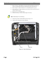
Refer to Figure 4-8. Route all harnesses to avoid pinching and screw posts.
12.
Refer top Figure 4-7. Ensure the battery access door is in the slot of the front cover
with the flat side facing in.
13.
Replace the cover and shoulder strap.
14.
Reinstall the battery. Connect a battery charger if necessary.
1RWH3HUIRUP6WHSRQD37[RQO\
15.
Perform the procedure Calibrate Ribbon Sensor on page 2-18.
16.
load the media, and perform an auto-calibration.
Ferrite
Cable Clip
Figure 4-8. Route Cable Harness
3DJH
/5HY
0DLQWHQDQFH
6HFWLRQ
5HSODFH3RZHU6XSSO\%RDUG
&DXWLRQ
2EVHUYHSURSHUHOHFWURVWDWLFVDIHW\SUHFDXWLRQVZKHQUHPRYLQJKDQGOLQJDQGUHSODFLQJ
SULQWHGFLUFXLWERDUGV
/5HY
1.
Turn the printer Off (2). Disconnect the battery charger.
2.
Slide the battery compartment door open and remove the battery.
3.
Lay the printer on a flat surface with the back facing up.
4.
Remove the two shoulder strap screws indicated in Figure 4-3. Set the shoulder
strap, two shoulder strap sleeves, and two shoulder strap screws aside.
5.
Remove the cover mounting screws.
6.
Remove the rear cover and set it aside.
7.
Refer to Figure 4-4 on page 4-10. Disconnect J2 (motor harness) and J1 (printhead
harness) from the power supply board.
8.
Refer to Figure 4-6 on page 4-12. Grasp the print mechanism module near the
access door top. Pivot it upward (the bottom of the print mechanism module is still
inside the printer front cover) and lift straight up. Set the print mechanism module
on the antistatic mat
9.
Refer to Figure 4-5. Lift the power supply and main logic boards out enough to clear
the front cover.
10.
Remove J12 (membrane switch ribbon cable).
11.
Refer to Figure 4-6. Hold the power supply board firmly with one hand, and gently
pull the main logic board away from the power supply board.
12.
Remove the rubber bezel from the battery/communication jacks on the power
supply board.
13.
Place the rubber bezel on the replacement power supply board.
14.
Hold the power supply board in one hand, and with the other hand gently push the
main logic board 40-pin plug into the power supply board 40-pin receptacle. The
bottom (noncomponent side) of the main logic board faces the battery contacts on
the power supply board.
15.
Refer to Figure 4-4 on page 4-10. Replace J12 (membrane switch ribbon cable).
16.
Refer to Figure 4-7. Ensure the battery access door is in the slot in the front cover
with the flat side facing in.
17.
Refer to Figure 4-5. Reinstall the power supply board and main logic board into the
front cover, ensuring the rubber bezel slides into the slots in the front cover.
18.
Refer to Figure 4-6 on page 4-12. Place the print mechanism, with the media access
door facing down, into the front cover by holding it at the top near the access door.
Slide the bottom of the print mechanism in first.
19.
Refer to Figure 4-4 on page 4-10 and replace J2 (motor harness) and J1 (printhead
harness). J2 and J1 are keyed and fit only one way. Do not force them into the
connectors.
20.
Refer to Figure 4-8. Route all harnesses to avoid pinching and screw posts.
3DJH
6HFWLRQ
0DLQWHQDQFH
21.
Refer to Figure 4-7. Ensure the battery access door is in the slot in the front cover
with the flat side facing in.
22.
Replace the cover and shoulder strap.
23.
Reinstall the battery. Connect a battery charger if necessary.
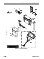
Figure 4-9. Disassemble/Assemble Power Supply Board & Main Logic Board
3DJH
/5HY
0DLQWHQDQFH
6HFWLRQ
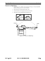
5HSODFH3ULQWKHDG$VVHPEO\
&DXWLRQ
'RQRWWRXFKWKHSULQWHOHPHQWVRQWKHSULQWKHDG7KHSULQWHOHPHQWVPD\EHKRWDQGZLOO
EXUQWKHVNLQ
&DXWLRQ 'RQRWWRXFKWKHSULQWHOHPHQWVRQWKHSULQWKHDG'LUWDQGPRLVWXUHIURPWKHKDQGVFDQ
SUHPDWXUHO\VKRUWHQWKHSULQWKHDGOLIH
1RWH7KHSULQWKHDGDVVHPEOLHVDUHIDFWRU\DGMXVWHG2WKHUWKDQDGMXVWLQJWKH
SULQWKHDGSUHVVXUHIRUPHGLDGRQRWPDNHDQ\DGMXVWPHQWV,IWKHVFUHZVPRXQWLQJWKH
SULQWKHDGDUHDGMXVWHGLWFDQFDXVHGDPDJHSUHPDWXUHSULQWKHDGIDLOXUHDQGSRRU
SULQWTXDOLW\
/5HY
1.
Turn the printer Off (2). Disconnect the battery charger.
2.
Slide open the battery compartment door and remove the battery.
3.
Open the media access door and remove any media.
4.
Stand the printer on a flat surface with the front facing you.
5.
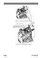
Refer to Figure 4-10. Remove the printhead assembly by first lifting the printhead
off the platen roller. Gently bend in one of the printhead pivot arms. Carefully pull
the printhead assembly out far enough to gain access to the cabling.
6.
Refer to Figure 4-11. Loosen, but do not remove, the screw securing the ground
wire(s). Remove the ground wire(s).
7.
Carefully slide the head-open switch wire off of the spade lug on the printhead.
8.
Refer to Figure 4-12. Carefully slide the 16-pin connector off of the printhead.
9.
Refer to Figure 4-11. (PT400 only) Carefully slide the 4-pin connector off of the
ribbon sensor board.
10.
Place the replacement printhead assembly into the print mechanism module by
reversing steps 5 through 9. Ensure the 16-pin connector on the printhead, the 4-pin
connector on the ribbon sensor board (PT400 only), the ground wire(s), and
head-open switch wire are connected to the printhead before operating. Ensure all
connections are fully seated.
11.
Install a battery, load the media, and calibrate the unit. Connect a battery charger if
necessary.
3DJH
6HFWLRQ
0DLQWHQDQFH
Figure 4-10. Remove/Install Printhead Assembly
Ribbon Sensor Board
Head-Open
Switch Wire
Ground wire (second ground wire
on the PT40x and replacement
wiring harnesses only).
Figure 4-11. Locate Printhead Ground Wire
3DJH
/5HY
0DLQWHQDQFH
6HFWLRQ
5HSODFH5LEERQ6HQVRU%RDUG$VVHPEO\
&DXWLRQ
'RQRWWRXFKWKHSULQWHOHPHQWVRQWKHSULQWKHDG7KHSULQWHOHPHQWVPD\EHKRWDQGZLOO
EXUQWKHVNLQ
&DXWLRQ 'RQRWWRXFKWKHSULQWHOHPHQWVRQWKHSULQWKHDG'LUWDQGPRLVWXUHIURPWKHKDQGVFDQ
SUHPDWXUHO\VKRUWHQWKHSULQWKHDGOLIH
&DXWLRQ
2EVHUYHSURSHUHOHFWURVWDWLFVDIHW\SUHFDXWLRQVZKHQUHPRYLQJKDQGOLQJDQGUHSODFLQJ
SULQWHGFLUFXLWERDUGV
/5HY
1.
Turn the printer Off (2). Disconnect the battery charger.
2.
Slide the battery compartment door open and remove the battery.
3.
Open the media access door and remove any media.
4.
Stand the printer on a flat surface with the front facing you.
5.
Refer to Figure 4-10. Remove the printhead assembly by first lifting the printhead
off the platen roller. Gently bend in one of the printhead pivot arms. Carefully pull
the printhead assembly out of the print mechanism module far enough to gain access
to the cabling.
6.
Refer to Figure 4-11. Loosen, but do not remove, the screw securing the two ground
wires. Remove the two ground wires.
7.
Carefully remove the head-open switch wire from the spade lug on the printhead.
8.
Refer to Figure 4-12 on page 4-20. Carefully slide the 16-pin connector off the
printhead.
9.
Refer to Figure 4-11 on page 4-18. Carefully slide the 4-pin connector off the ribbon
sensor board.
10.
Refer to Figure 4-13. Remove the ribbon sensor board by sliding the tip of a 1/4 in.
flat-blade screwdriver under the tab approximately 1/4 in. (6.4 mm).
11.
Gently lift up on the screwdriver handle until the screwdriver is perpendicular to the
printhead assembly. The ribbon sensor board slides away from the printhead
assembly.
12.
Refer to Figure 4-14. Slide the replacement ribbon sensor board into the printhead
assembly until the tab locks into the cutout on the board.
13.
Reinstall the printhead assembly into the print mechanism module by reversing
steps 5 through 9. Ensure the 16-pin connector on the printhead, the 4-pin connector
on the ribbon sensor board, the two ground wires, and head-open switch wire are
connected to the printhead before operating. Make sure all connections are fully
seated.
14.
Install a battery. Connect a battery charger if necessary.
15.
Perform the Calibrate Ribbon Sensor on page 2-18.
16.
load the media, and perform an Auto-Calibration on page 2-17.
3DJH
6HFWLRQ
0DLQWHQDQFH
1. Insert screwdriver
tip between plug
and receptacle.
Do not adjust
or remove
these screws.
2. Carefully twist screwdriver
to pry apart.
Plug
Receptacle
Figure 4-12. Locate Printhead 16-Pin Connector
3DJH
/5HY
0DLQWHQDQFH
6HFWLRQ
Tab
Ribbon Sensor Board
1. Slide a 1/4 in.(6.4 mm) flat-blade
screwdriver under the tab
(about 1/4 in.)(6.4 mm).
2. Gently lift up on the screwdriver
handle until the screwdriver is
perpendicular to the printhead
assembly and ribbon sensor board.
3. The ribbon sensor board slides
away from the printhead assembly.
Figure 4-13.
Remove Ribbon Sensor Board
Tab
Cutout
Ribbon Sensor Board
Figure 4-14. Install Ribbon Sensor Board
/5HY
3DJH
6HFWLRQ
0DLQWHQDQFH
5HSODFH3ULQW0HFKDQLVP0RGXOH
&DXWLRQ
'RQRWWRXFKWKHSULQWHOHPHQWVRQWKHSULQWKHDG7KHSULQWHOHPHQWVPD\EHKRWDQGZLOO
EXUQWKHVNLQ
&DXWLRQ 'RQRWWRXFKWKHSULQWHOHPHQWVRQWKHSULQWKHDG'LUWDQGPRLVWXUHIURPWKHKDQGVFDQ
SUHPDWXUHO\VKRUWHQWKHSULQWKHDGOLIH
&DXWLRQ
2EVHUYHSURSHUHOHFWURVWDWLFVDIHW\SUHFDXWLRQVZKHQUHPRYLQJKDQGOLQJDQGUHSODFLQJ
SULQWHGFLUFXLWERDUGV
3DJH
1.
Turn the printer Off (2). Disconnect the battery charger.
2.
Slide the battery compartment door open and remove the battery.
3.
Open the media access door and remove any media.
4.
Stand the printer on a flat surface with the front facing you.
5.
Refer to Figure 4-10. Remove the printhead assembly by first lifting the printhead
off the platen roller. Gently bend in one of the printhead pivot arms. Carefully pull
the printhead assembly out of the print mechanism module far enough to gain access
to the cabling.
6.
Refer to Figure 4-11. Loosen, but do not remove, the screw securing the ground
wire(s). Remove the ground wire(s).
7.
Carefully slide the head-open switch wire off the spade lug on the printhead.
8.
Refer to Figure 4-12. Carefully slide the 16-pin connector off the printhead.
9.
Refer to Figure 4-11. (PT400 only) Carefully slide the 4-pin connector off the
ribbon sensor board.
10.
Set the printhead assembly on the antistatic mat.
11.
Close the media access door and set the printer down with the back facing up.
12.
Remove the two shoulder strap screws indicated in Figure 4-3. Set the shoulder
strap, the two shoulder strap sleeves, and the two shoulder strap screws aside.
13.
Remove the cover mounting screws.
14.
Lift the rear cover off and set it aside.
15.
Refer to Figure 4-4 on page 4-10. Disconnect J2 (motor harness) and J1 (printhead
harness) from the power supply board.
16.
Refer to Figure 4-6 on page 4-12. Grasp the print mechanism module near the
access door front. Pivot it up (the bottom of the print mechanism module is still
inside the printer cover front) and lift straight up.
17.
Set the replacement print mechanism module into the front cover, with the media
access door facing down, by holding it at the top near the access door. Slide in the
bottom of the print mechanism first.
/5HY
0DLQWHQDQFH
6HFWLRQ
18.
Refer to Figure 4-6 on page 4-12 and replace J2 (motor harness) and J1 (printhead
harness). J2 and J1 are keyed and fit only one way. Do not force them into the
connectors.
19.
Refer to Figure 4-8 on page 4-14. Route all harnesses to avoid pinching and screw
posts.
20.
Refer to Figure 4-7 on page 4-13. Ensure the battery access door is in the slot in the
front cover with the flat side facing in.
21.
Replace the cover and shoulder strap.
22.
Place the printhead assembly into the replacement print mechanism module by
reversing steps 5 through 9. Ensure the 16-pin connector on the printhead, the 4-pin
connector on the ribbon sensor board (PT40x only), the ground wire(s), and
head-open switch wire are connected to the printhead before operating. Ensure all
connections are fully seated.
23.
Close and latch the print mechanism module access door.
24.
Install a battery, load the media, and calibrate the unit. Connect a battery charger if
necessary.
5HSODFH:LULQJ+DUQHVV
&DXWLRQ
'RQRWWRXFKWKHSULQWHOHPHQWVRQWKHSULQWKHDG7KHSULQWHOHPHQWVPD\EHKRWDQGZLOO
EXUQWKHVNLQ
&DXWLRQ 'RQRWWRXFKWKHSULQWHOHPHQWVRQWKHSULQWKHDG'LUWDQGPRLVWXUHIURPWKHKDQGVFDQ
SUHPDWXUHO\VKRUWHQWKHSULQWKHDGOLIH
&DXWLRQ
2EVHUYHSURSHUHOHFWURVWDWLFVDIHW\SUHFDXWLRQVZKHQUHPRYLQJKDQGOLQJDQGUHSODFLQJ
SULQWHGFLUFXLWERDUGV
/5HY
1.
Turn the printer Off (2). Disconnect the battery charger.
2.
Slide the battery compartment door open and remove the battery.
3.
Open the media access door and remove any media.
4.
Stand the printer on a flat surface with the front of the printer facing you.
5.
Refer to Figure 4-10 on page 4-18. Remove the printhead assembly by first lifting
the printhead off the platen roller. Gently bend in one of the printhead pivot arms.
Carefully pull the printhead assembly out of the print mechanism module far enough
to gain access to the cabling.
6.
Refer to Figure 4-11 on page 4-18. Loosen, but do not remove, the screw securing
the ground wire(s). Remove the ground wire(s).
7.
Carefully slide the head-open switch wire off the spade lug on the printhead.
8.
Refer to Figure 4-12 on page 4-20. Carefully remove the 16-pin connector from the
printhead.
9.
(PT40x only)Carefully remove the 4-pin connector from the ribbon sensor board.
3DJH
6HFWLRQ
3DJH
0DLQWHQDQFH
10.
Set the printhead assembly on the antistatic mat. Close the media access door and
place the printer face down.
11.
Remove the two shoulder strap screws indicated in Figure 4-3 on page 4-8. Set the
shoulder strap, the two shoulder strap sleeves, and the two shoulder strap screws
aside.
12.
Remove the cover mounting screws.
13.
Lift the rear cover off and set it aside.
14.
Refer to Figure 4-4 on page 4-10. Disconnect J2 (motor harness) and J1 (printhead
harness) from the power supply board.
15.
Refer to Figure 4-15. Disconnect the outer media sensor cable located in the middle
rear of the print mechanism module.
16.
Disconnect the inner media sensor cable on the left side frame (motor side) of the
print mechanism module.
17.
Grasp the print mechanism module by the media access door top (see Figure 4-6).
Pivot it up (the bottom of the print mechanism module is still inside the printer
cover top) and lift straight up.
18.
Place the print mechanism module on a flat surface with the media access door
facing up.
19.
Open the media access door.
20.
Refer to Figure 4-16. Using your thumbs, gently spread the two side frames of the
print mechanism module apart enough for the access door top to slip off the hinge
pins.
21.
Remove the entire wiring harness and top access door from the print mechanism
module.
22.
Install the new top access door and harness into the print mechanism module and
slide it against one of the hinge pins. Gently spread the side frame opposite the
hinge pin engaged with the top access door. Slide the top access door into the second
hinge pin.
23.
Refer to Figure 4-8 on page 4-14. Install the new wiring harness in the print
mechanism module.
24.
Refer to Figure 4-6 on page 4-12. Place the print mechanism module into the front
cover, with the media access door facing down, by holding it at the top near the
media access door. Slide in the bottom of the print mechanism first.
25.
Refer to Figure 4-15. Reconnect the outer media sensor cable and Inner Media
Sensor cable.
26.
Refer to Figure 4-4 on page 4-10 and replace J2 (motor harness) and J1 (printhead
harness). J2 and J1 are keyed and fit only way. Do not force them into the
connectors.
27.
Refer to Figure 4-8 on page 4-14. Route all harnesses to avoid pinching and screw
posts.
28.
Refer to Figure 4-7 on page 4-13. Ensure the battery access door is in the slot in the
front cover with the flat side facing in.
29.
Replace the rear cover and shoulder strap.
/5HY
0DLQWHQDQFH
6HFWLRQ
1RWH7KHUHSODFHPHQWZLULQJKDUQHVVDVVHPEO\LVGHVLJQHGIRUXVHRQERWKWKH
3$[DQG37[$QDGGLWLRQDOJURXQGZLUHOHDGLQJIURPEHQHDWKWKHPHWDOVKLHOG
LQVLGHWKHWRSFRYHUVKRZQLQ)LJXUH RQSDJHLWHPDWWDFKHVWRWKHJURXQG
VFUHZRQWKHSULQWKHDG&RQQHFWWKHDGGLWLRQDOJURXQGZLUHWRWKHJURXQGVFUHZRQWKH
SULQWKHDGZKHQXVLQJWKHZLULQJKDUQHVVRQWKH3$[DQG37[VHH)LJXUH RQ
SDJH
30.
Reinstall the printhead assembly by reversing steps 5 through 9. Ensure the 16-pin
connector, 4-pin connector on the ribbon sensor board (PT400 only), two ground
wires, and head-open switch wire are connected to the printhead before operating.
Ensure all connections are fully seated.
31.
Close and latch the print mechanism module media access door.
32.
Install a battery, load the media, and calibrate the unit. Connect a battery charger if
necessary.
Inner Media Sensor
Outer Media Sensor
Front View
Rear View
Figure 4-15. Sensor Connector Location
Access Door Top
Figure 4-16. Removing the Access Door Top
/5HY
3DJH
6HFWLRQ
0DLQWHQDQFH
5HSODFH0HPEUDQH6ZLWFK$VVHPEO\
&DXWLRQ
2EVHUYHSURSHUHOHFWURVWDWLFVDIHW\SUHFDXWLRQVZKHQUHPRYLQJKDQGOLQJDQGUHSODFLQJ
SULQWHGFLUFXLWERDUGV
3DJH
1.
Turn the printer Off (2). Disconnect the battery charger.
2.
Slide the battery compartment door open and remove the battery.
3.
Lay the printer on a flat surface with the back of the printer facing up.
4.
Remove the two shoulder strap screws indicated in Figure 4-3 on page 4-8. Set the
shoulder strap, two shoulder strap sleeves, and two shoulder strap screws aside.
5.
Remove the cover mounting screws.
6.
Lift the rear cover off and set it aside.
7.
Refer to Figure 4-4 on page 4-10. Disconnect J2 (motor harness) and J1 (printhead
harness) from the main logic board.
8.
Refer to Figure 4-6 on page 4-12. Grasp the print mechanism module by the access
door top. Pivot it upward (the bottom of the print mechanism module is still inside
the printer front cover) and lift straight up. Set the print mechanism module on the
antistatic mat.
9.
Refer to Figures 4-4 and 4-5 on pages 4-10 and 4-11. Carefully lift the power supply
board and main logic board out enough to get access to J12 (membrane switch
ribbon cable).
10.
Remove J12 (membrane switch ribbon cable).
11.
Place both boards on the antistatic mat.
12.
Refer to Figure 4-7 on page 4-13. Lift the battery access door up and out of the top
cover.
13.
Refer to Figure 4-17. Turn the front cover face up and, using a 1/4 in. flat-blade
screwdriver, carefully pry the defective membrane switch assembly away from the
front cover.
14.
Using isopropyl alcohol to clean the area on the front cover where the membrane
switch assembly was located. Remove as much of the old adhesive as possible.
15.
Remove the liner on the replacement membrane switch assembly. With the LEDs
facing the top edge of the cover, thread the ribbon cable through the cutout in the
front cover. Once in place, press around the membrane switch assembly so the
adhesive makes contact with the front cover and the switch is secure. Allow time for
the adhesive to dry.
16.
Place the front cover face down.
17.
Refer to Figure 4-4 on page 4-10. Ensure the contacts on the membrane switch
ribbon cable face away from the edge of the main logic board where J12 is found.
Install the membrane switch ribbon cable into J12.
18.
Refer to Figure 4-5 on page 4-11. Slide the power supply board and main logic
board into the front cover. Ensure the rubber bezel slides into the slots in the front
cover.
/5HY
0DLQWHQDQFH
6HFWLRQ
19.
Refer to Figure 4-6 on page 4-12. Place the print mechanism, with the media access
door facing down, into the front cover by holding it at the top near the access door.
Slide in the bottom of the print mechanism first.
20.
Refer to Figure 4-3 on page 4-8 and replace J2 (motor harness) and J1 (printhead
harness). J2 and J1 are keyed and fit only one way. Do not force them into the
connectors.
21.
Refer to Figure 4-8 on page 4-14. Route all harnesses to avoid pinching and screw
posts.
22.
Refer to Figure 4-7 on page 4-13. Ensure the battery access door is in the slot in the
front cover with the flat side facing in.
23.
Replace the cover and shoulder strap.
24.
Install a battery, load the media, and test the unit. Connect a battery charger if
necessary.
Figure 4-17. Membrane Switch Assembly
/5HY
3DJH
6HFWLRQ
0DLQWHQDQFH
5HSDLU0HGLD*XLGH
&DXWLRQ
'RQRWWRXFKWKHSULQWHOHPHQWVRQWKHSULQWKHDG7KHSULQWHOHPHQWVPD\EHKRWDQGZLOO
EXUQWKHVNLQ
&DXWLRQ 'RQRWWRXFKWKHSULQWHOHPHQWVRQWKHSULQWKHDG'LUWDQGPRLVWXUHIURPWKHKDQGVFDQ
SUHPDWXUHO\VKRUWHQWKHSULQWKHDGOLIH
&DXWLRQ
2EVHUYHSURSHUHOHFWURVWDWLFVDIHW\SUHFDXWLRQVZKHQUHPRYLQJKDQGOLQJDQGUHSODFLQJ
SULQWHGFLUFXLWERDUGV
Refer to Figure 4-18. The media guides are part of the print mechanism assembly. If they
are broken, the entire print mechanism assembly must be replaced. If the media guides are
simply bent out of shape, perform the procedure listed below.
1RWH7KHSULQWKHDGDVVHPEO\LVUHPRYHGWRDYRLGGDPDJHZKHQEHQGLQJWKHPHGLD
JXLGHV
3DJH
1.
Turn the printer Off (2). Disconnect the battery charger.
2.
Slide the battery compartment door open and remove the battery.
3.
Open the media access door and remove any media.
4.
Stand the printer on a flat surface with the front of the printer facing you.
5.
Refer to Figure 4-10 on page 4-18. Remove the printhead assembly by first lifting
the printhead off the platen roller. Gently bend in on one of the printhead pivot arms.
Carefully pull the printhead assembly out of the print mechanism module far enough
to gain access to the cabling.
6.
Refer to Figure 4-11 on page 4-18. Loosen, but do not remove, the screw securing
the ground wire. Remove the ground wire.
7.
Carefully disconnect the head-open switch wire from the spade lug on the printhead.
8.
Refer to Figure 4-12 on page 4-20. Carefully disconnect the 16-pin connector from
the printhead.
9.
(PT40x only) Refer to Figure 4-11 on page 4-18. Carefully disconnect the 4-pin
connector from the ribbon sensor board.
10.
Using needle-nose pliers, carefully bend the media guides so the vertical portions
are perpendicular to the platen roller and the horizontal portions are parallel to the
roller.
11.
Replace the printhead assembly into the print mechanism module by reversing
steps 5 through 9. Ensure the 16-pin connector on the printhead, 4-pin connector on
the ribbon sensor board (PT400 only), ground wire, and head-open switch wire are
connected to the printhead before operating. Ensure all connections are fully seated.
12.
Close and latch the print mechanism module media access door.
/5HY
0DLQWHQDQFH
6HFWLRQ
13.
Install a battery, load the media, and calibrate the unit. Connect a battery charger if
necessary.
Ensure that the
horizontal portion of
the media guides
are parallel to the
platen roller.
Ensure that the
vertical portion of
the media guides
are perpendicular
to the platen roller.
Figure 4-18. Adjust Media Guide
/5HY
3DJH
6HFWLRQ
0DLQWHQDQFH
,U'$%RDUGDQG&DEOH5HSODFHPHQW
1.
Turn the printer Off (2). Disconnect the battery charger.
2.
Slide the battery compartment door open and remove the battery.
3.
Lay the printer on a flat surface with the back facing up.
4.
Remove the two shoulder strap screws indicated in Figure 4-3 on page 4-8. Set the
shoulder strap, shoulder strap sleeves, and shoulder strap screws aside.
5.
Remove the rear cover mounting screws.
6.
Lift the rear cover off and set it aside.
7.
Refer to Figure 4-19. Unplug the IrDA cable from the IrDA board.
8.
If replacing the IrDA board only, slide the IrDA board out of the printer.
9.
If replacing the cable, unplug it from the main logic board, and remove it from the
wire clips.
10.
Replace the cable by plugging it into the IrDA board.
11.
Insert the IrDA board as shown.
12.
Dress the IrDA Cable and secure it with the wire clips.
13.
Plug the remaining connnector into the main logic board.
14.
Replace the rear cover and shoulder strap.
15.
Reinstall the battery, load the media, and test the unit. Connect a battery charger if
necessary.
MLB IrDA
Connection
Wire Clip
IrDA Cable
IrDA Board
Assembly
Route the cable as shown.
Figure 4-19. Install IrDA Cable and Board
3DJH
/5HY
6HFWLRQ
Battery Access Door
0.25 in.
(6.35 mm)
3.9375 in.
(100 mm)
2.75 in.
(69.8 mm)
0DLQWHQDQFH
Figure 4-20. Mounting Hole Template
/5HY
3DJH
6HFWLRQ
0DLQWHQDQFH
3DJH
/5HY
0DLQWHQDQFHDQG$VVHPEO\'UDZLQJV
6HFWLRQ
6HFWLRQ
0DLQWHQDQFHDQG$VVHPEO\'UDZLQJV
'UDZLQJDQG3DUWV/LVW
Use Figures 5-1 and 5-2 when identifying PA400/403 and PT400/403 printer parts,
assemblies, and kits for troubleshooting and repair. For replacement parts and pricing,
contact your Zebra distributor. Tables 5-1 and 5-2 list replacement parts and kits available
for the PA400/403 and PT400/403 printer. Some of these are available only in kit form or
as subassemblies.
1RWH1RSLHFHSDUWVLQWKHVHNLWVRUVXEDVVHPEOLHVXQOHVVRWKHUZLVHOLVWHGDUH
DYDLODEOHVHSDUDWHO\
/5HY
3DJH
Maintenance and Assembly Drawings
Section 5
Table 5-1 Replacement Parts and Assemblies (See Figur
e 5-1)
Item
Qty
Part Number
1
1
505086
X
X
X
X
Tear Blade
2
1
505145M
X
X
X
X
Printhead Assembly
3
1
505040M
X
1
505040-02M
4
1
505014
X
X
5
1
580018M
X
X
6
1
58008M
X
X
1
52700M
7
1
505073
X
8
1
505004M
9
10
1
1
562005M
81519
1
82330
1
AA6002-1
1
AA6002-2
11
1
580013M
12
1
52582M
X
X
X
X
IrDA PCBAssy. (IR units only)
13
1
52711M
X
X
X
X
IrDA Cable (IR units only)
14
1
44176
X
X
X
X
Clip, Wire (IR units only)
505142L Rev. 3 5/12/03
PA400 PT400 PA403 PT 403
X
X
Description
Print Mechanism Module
Assy.
X
(less Printhead
Assembly)
X
X
Battery AccessDoor
X
X
Power Board
X
X
X
X
X
Cover Screws (quantity of 20)
X
X
X
X
Membrane Switch
X
X
X
X
X
X
Main Logic Board
Cable Harness/Sensor
Assy.
Housing Logo
X
X
X
X
Ribbon Sensor Board
Page 5-2
6HFWLRQ
0DLQWHQDQFHDQG$VVHPEO\'UDZLQJV
2
11
1
3
4
8
5
13
12
14
6
9
7
10
Figure 5-1.
3DJH
Main Printer Drawing
/5HY
0DLQWHQDQFHDQG$VVHPEO\'UDZLQJV
6HFWLRQ
7DEOH2SWLRQDQG$FFHVVRU\.LWV
,WHP
4W\
3DUW1XPEHU
'HVFULSWLRQ
9$&&KDUJHU
$FFHVVRU\&DEOH5-'%
8QLYHUVDO&KDUJHU:LWKRXW3RZHU&RUG
3RZHU&RUG8.,(&&
3RZHU&RUG$XVW,(&&
3RZHU&RUG(XUR,(&&
3RZHU&RUG86,(&&
0
=HEUD)DVWUDSDQG+DUGZDUH.LW
0
6WDQGDUG%DWWHU\P$K86&DQDGD
0
([WHQGHG/LIH%DWWHU\P$K86&DQDGD
UMAN-PA/PT40x
3$37[8VHU*XLGH
/
=3/,,8VHU*XLGH
/5HY
3DJH
0DLQWHQDQFHDQG$VVHPEO\'UDZLQJV
6HFWLRQ
1
2
Power Cord
Varies by
Country
4
3
5
6
7
8
Figure 5-2.
/5HY
Option and Accessory Kits
3DJH
6HFWLRQ
0DLQWHQDQFHDQG$VVHPEO\'UDZLQJV
3RZHU6XSSO\%RDUG/D\RXW
J1
(Printhead)
J2
(Stepper Motor)
J7
(Logic Board)
J12
(Membrane Switch)
Front
J5
(RJ45 Jack)
J9
(Battery Charger Jack)
Back
Figure 5-3. Power Supply Board Layout
3DJH
/5HY
0DLQWHQDQFHDQG$VVHPEO\'UDZLQJV
6HFWLRQ
0DLQ/RJLF%RDUG/D\RXW
Figure 5-4. Main Logic Board Layout
/5HY
3DJH
6HFWLRQ
3DJH
0DLQWHQDQFHDQG$VVHPEO\'UDZLQJV
/5HY