1
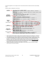
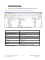
Development Kit - ERTEC 200 PN IO User Guide Copyright © Siemens AG 2008. All rights reserved. Technical data subject to change 1 DK_ERTEC200_PNIO_Description Version 3.0.0 Edition (07/2008) Disclaimer of Liability We have checked the contents of this manual for agreement with the hardware and software described. Since deviations cannot be precluded entirely, we cannot guarantee full agreement. However, the data in this manual are reviewed regularly. Necessary corrections are included in subsequent editions. Suggestions for improvement are welcomed. Copyright © Siemens AG 2008. All rights reserved The reproduction, transmission or use of this document or its contents is not permitted without express written authority. Offenders will be liable for damages. All rights, including rights created by patent grant or registration of a utility model or design, are reserved. All product and system names are registered trademarks of their respective owner and must be treated as such. Technical data subject to change. Copyright © Siemens AG 2008. All rights reserved. Technical data subject to change 2 DK_ERTEC200_PNIO_Description Version 3.0.0 Preface Purpose of this Manual This user guide describes the software functionality of the ERTEC 200 evaluation board. Introduction Software functions Example for the user Target Audience of this Manual This manual is intended for software developers who want to use the ERTEC 200 for new products. This requires the following basic knowledge: • Programming capability in C/C++ • Programming techniques such as multi-threading and callback routines • Knowledge of the PROFINET IO system • General knowledge of automation engineering • Basic knowledge of the STEP 7 or NCM PC configuration software The developer is provided with a development kit, consisting of an ERTEC 200 evaluation board and a PROFINET IO software package. The developer uses this kit to perform tests on his PROFINET IO device application with the VxWorks operating system. Structure of this Manual This manual describes the ERTEC 200 evaluation board. The manual is structured as follows: o Section 1 Introduction o Section 2 Commissioning the User Example with VxWorks Operating System o Section 3 PROFINET IO Software Settings o Section 4 Creating a GSD File o Section 5 SNMP Description o Section 6 Important Information and Limitations o Section 7 List of Terms and References Copyright © Siemens AG 2008. All rights reserved. Technical data subject to change 3 DK_ERTEC200_PNIO_Description Version 3.0.0 This manual includes a description of the PROFINET IO stack for the EB 200 evaluation board that is updated as necessary. You can find the current version of the manual on the Internet at http://www.siemens.com/comdec. Guide To help you quickly find the information you need, this manual contains the following aids: o A complete table of contents as well as a list of all figures and tables in the manual are provided at the beginning of the manual. o A glossary containing definitions of important terms used in the manual is located following the appendices. o References to other documents are indicated by the document reference number enclosed in slashes (/No./). The complete title of the document can be obtained from the list of references at the end of the manual. Additional Support If you have questions regarding use of the described block that are not addressed in the documentation, please contact your Siemens representative. Please send your written questions, comments, and suggestions regarding the manual to the hotline via the email address indicated above. In addition, you can receive general information, current product information, FAQs, and downloads pertaining to your application on the Internet at: http://www.siemens.com/comdec Technical Contacts for Germany / Worldwide Siemens AG Automation & Drives ComDeC Phone: Phone: Fax: E-mail: 0911/750-2736 0911/750-2080 0911/750-2100 [email protected] Street address: Mailing address: Würzburgerstr.121 P.O. Box 2355 90766 Fürth Federal Republic of Germany 90713 Fürth Federal Republic of Germany Technical Contacts for USA PROFI Interface Center: One Internet Plaza PO Box 4991 Johnson City, TN 37602-4991 Fax: (423)- 262- 2103 Phone: (423)- 262- 2576 E-mail: [email protected] Copyright © Siemens AG 2008. All rights reserved. Technical data subject to change 4 DK_ERTEC200_PNIO_Description Version 3.0.0 Contents 1 Introduction ............................................................................................................................7 1.1 1.2 1.3 1.4 2 Scope of Delivery ................................................................................................................................... 7 Content and Target Audience of this User Guide................................................................................... 7 Additional Information............................................................................................................................. 7 Procedure when Using ERTEC 200 to Develop Your Own PROFINET IO Device ................................ 8 Commissioning the User Example with VxWorks Operating System ..............................9 2.1 Requirements ......................................................................................................................................... 9 2.2 Required Knowledge .............................................................................................................................. 9 2.3 Hardware Installation.............................................................................................................................. 9 2.4 Installation of STEP 7/NCM PC and the EB 200 GSD File..................................................................... 10 2.5 Creating a PROFINET IO Configuration with STEP 7 ............................................................................ 12 2.5.1 Assigning the IP Address for the IO Controller .............................................................................. 13 2.5.2 Assigning the Device Name........................................................................................................... 14 2.5.3 STEP 7 Example Program............................................................................................................. 14 2.5.4 Downloading the STEP 7 Program and the PROFINET IO Bus Configuration .............................. 15 2.6 Creating a PROFINET IO Configuration with NCM PC .......................................................................... 16 2.7 Installing the CP1616 Controller............................................................................................................. 17 2.8 Compiling the Device Firmware with Windriver Development Tools ...................................................... 17 2.8.1 Installation of Windriver Tools Tornado 2.2.1 for ARM9 and PID 2.0............................................. 17 2.8.1.1 First-Time Installation of Windriver Software......................................................................... 17 2.8.1.2 Tornado 2.2.1 for ARM9 is already installed ......................................................................... 17 2.8.1.3 Tornado 2.2.1 for ARM9 and PID2.0 Full Version are already installed................................ 17 2.8.1.4 Conversion from the PID 2.0 Evaluation License to a PID 2.0 Full License .......................... 17 2.8.1.5 Generate the PID2.0 Network Library ................................................................................... 17 2.8.2 Transferring the EB 200 BSP to the Tornado Directory ................................................................. 18 2.8.3 Transfering the file bootConfig.c to the Tornado Directory............................................................. 18 2.8.4 Transferring Example Sources, Project Files, and Compiled PNIO Objects .................................. 19 2.8.5 Compiling a PROFINET IO Device Example Application............................................................... 20 2.8.6 Preparing to Commission the Complete System ........................................................................... 21 2.8.6.1 Configuring the FTP Server .................................................................................................. 21 2.8.6.2 Configuring the Terminal Program for Message Displays ..................................................... 22 2.8.7 Downloading User Software to the Evaluation Board .................................................................... 23 2.8.7.1 Displaying Messages on the Terminal .................................................................................. 23 2.9 Support for Commissioning Problems .................................................................................................... 28 3 PROFINET IO Software Setting.............................................................................................29 3.1 Directory Structure of the DK-ERTEC 200 PN IO V3.0 Development Kit CD......................................... 29 3.2 Configuration and User Files for the Application .................................................................................... 30 3.3 Interface Description .............................................................................................................................. 31 4 5 Creating GSD Files.................................................................................................................32 SNMP (Simple Network Management Protocol)..................................................................33 5.1 5.2 5.3 5.4 5.5 5.6 6 Important Information and Limitations ................................................................................35 6.1 6.2 6.3 6.4 6.5 7 Diagnostics via SNMP............................................................................................................................ 33 Management Information Base MIBs ..................................................................................................... 33 SNMPv1 and SNMPv2 Protocols ........................................................................................................... 33 SNMP Communities ............................................................................................................................... 33 Definition of Abbreviations and Source for Additional Information.......................................................... 33 Variables of the MIB II Standard ............................................................................................................ 33 Number of PNIO Devices ....................................................................................................................... 35 Parameters for One Device.................................................................................................................... 35 Maximum Number of User Data for One Device .................................................................................... 35 Functional Limitations............................................................................................................................. 35 Resource Requirements......................................................................................................................... 35 Miscellaneous.........................................................................................................................36 7.1 Abbreviations/List of Terms:................................................................................................................... 36 7.2 References: ............................................................................................................................................ 37 Copyright © Siemens AG 2008. All rights reserved. Technical data subject to change 5 DK_ERTEC200_PNIO_Description Version 3.0.0 List of Figures Figure 1: PROFINET IO Device with EB 200 in a Minimum Configuration ............................................................ 10 Figure 2: EB 200 Evaluation Board Imported in hardware catalog of SIMATIC Manager...................................... 11 Figure 3: EB 200 Evaluation Board Imported in hardware catalog of NCM PC ..................................................... 11 Figure 4: Configuring a PROFINET Device with EB 200 in HW CONFIG ............................................................. 12 Figure 5: Identifying the MAC and IP addresses of a Connected PNIO Controller ................................................ 13 Figure 6: Entering the Configured IP Address and Subnet Mask and Assigning PNIO Controllers ....................... 14 Figure 7: Downloading an Example Program to the S7 CPU ................................................................................ 15 Figure 8: Configuring a PROFINET Device with EB 200 in NCM PC CONFIG ..................................................... 16 Figure 9: Copying the Board Support Package for EB 200 to the Working Directory ............................................ 18 Figure 10: Copying the DevKit200 Example to the Project Directory of Tornado .................................................. 19 Figure 11: Configuring the FTP Server.................................................................................................................. 22 Figure 12: Overview of Connection for Downloading the Application Software for Device .................................... 23 Figure 13: EB 200 Power Up Message on Message Terminal .............................................................................. 23 Figure 14: Input Options for EB 200 on Message Terminal................................................................................... 24 Figure 15: Displaying Boot Parameters of EB 200 on Message Terminal ............................................................. 24 Figure 16: Changing Boot Parameters of EB 200 on Message Terminal .............................................................. 25 Figure 17: EB 200 Messages following Successful Download and start of the device application ........................ 26 Figure 18: Directory Structure of the DK-ERTEC 200 PN IO V3.0 Development Kit CD ....................................... 29 List of Tables Table 1: Overview of PNIO Controller Blocks for Example Project........................................................................ 15 Table 2: Overview of Possible Problems when Commissioning Device ................................................................ 28 Table 3: Description of Directories......................................................................................................................... 29 Table 4: Files of the example application .............................................................................................................. 30 Copyright © Siemens AG 2008. All rights reserved. Technical data subject to change 6 DK_ERTEC200_PNIO_Description Version 3.0.0 1 Introduction PROFINET IO is an automation concept within PROFINET for implementation of modular, distributed applications. With PROFINET IO, you create automation solutions using the same familiar methods as with PROFIBUS. PROFINET IO is implemented with both the PROFINET standard for automation devices and the STEP 7 engineering tool. This means that you have virtually the same application view in STEP 7 – regardless of whether you are configuring PROFINET or PROFIBUS devices. Thus, programming of your user program is nearly identical for PROFINET and PROFIBUS. A software stack is provided for PROFINET IO. This enables cost-effective creation of PROFINET IO devices. This stack eliminates the need for the user to create an entire communication software program. The stack functionality includes: • • • Cyclic RT and IRT data exchange with a PROFINET IO controller Sending and receiving of diagnostic and process alarms, and plug and pull alarms Assignment of IP addresses and device names via Ethernet A good knowledge of PROFINET IO is required to implement the firmware stack. 1.1 Scope of Delivery ¾ ¾ ¾ ¾ EB 200 (PN IO device) CP1616 (PN IO controller) Software CDs Cables The supplied CD contains: • Software and application example of the PROFINET IO protocol stack • Board support package (BSP) for EB 200 • Example GSDML file for integration in STEP 7 HWCONFIG • Example GSDML file for integration in NCM PC CONFIG • Development kit documentation PROFINET IO stack, application example and BSP are available in C source code for an PROFINET IO device. 1.2 Content and Target Audience of this User Guide This document is intended for developers of PROFINET IO devices. It includes the following: • • • • Overview of the development kit structure Description and configuration of the required tools Description and generation of the user example Description of an executable PROFINET IO entire system This document does not include the following: • • • 1.3 Overview of PROFINET IO Description of the PROFINET IO bus protocols Detailed description of the PROFINET IO stack structure and processes Additional Information The supplied application example was tested on an ERTEC 200 evaluation board. Copyright © Siemens AG 2008. All rights reserved. Technical data subject to change 7 DK_ERTEC200_PNIO_Description Version 3.0.0 1.4 Procedure when Using ERTEC 200 to Develop Your Own PROFINET IO Device The DK-ERTEC200 PN IO development kit contains several CDs. A reference to these CDs is provided in subsequent sections. Procedure How to Develop Your Own PROFINET IO Device Software Quickly and Easily Step 1 2 3 4 5 6 7 8 Procedure Install the Tornado 2.2.1 development tools (Note1) on your PC (Section 2.8.1). Install the NCM-PC configuration tool (Note2) or STEP 7 (Note3) on your PC (Section 2.4). Copy the board support package for the development kit in the Tornado project directory (Section 2.8.2) (Note4) Copy the PROFINET IO application example and the PROFINET IO device stack in the Tornado project directory (Section 2.8.4) and generate a downloadable PROFINET-IO device program code (Section 2.8.5) Configure the following tools: • FTP server (Section 2.8.6.1) • Terminal (Section 2.8.6.2) Install PROFINET IO configuration example for CP1616 or CPU319 3 PN/DP: • Copy GSD file + bit map file (Section 2.4) • Copy configuration example (Section 0 or 2.6) Download the example PROFINET IO device program and familiarize yourself with the application example. Make your changes and adjustments in the application example step-by-step and test them on the EB200 hardware. a device with ERTEC 200 needs 3 MAC addresses: • • 9 10 one MAC address per Port for the neighborhood relationship (LLDP protocol). one MAC address for the Device. The Function „BSP_GET_MAC_ADR();“ is an example and must be changed with your settings. change the manufacturer specific identification for your device. Example: usriod_cfg.h Æ RT = 1 change the manufacturer specific identification in File usriod_main_rt.c After you have successfully tested your software on the EB 200, adapt the example program to your hardware and test the program on your target hardware. (Note5): Note: 1: This software requires a license. You can obtain this license from Windriver. 2: This software does not require a license. 3: This software is not included in the development kit and requires a license. You can obtain this software and license from Siemens. 4: When testing the PROFINET IO device application on the EB 200, adjustments in the example program are normally not necessary. 5: For your target hardware, adjustments are necessary in the BSP if you are not using the suggested „Minimum configuration for a PROFINET IO device“ hardware or if your own drivers are to be linked. Due to the PHYs, please note the information in the EB200 manual. Copyright © Siemens AG 2008. All rights reserved. Technical data subject to change 8 DK_ERTEC200_PNIO_Description Version 3.0.0 2 2.1 Commissioning the User Example with VxWorks Operating System Requirements The PNIO Development Kit provides a complete user example for a PROFINET IO device. It can be executed on the Siemens AG ERTEC 200 evaluation board. This section explains how to commission a PROFINET IO system, consisting of a PN-IO controller and a PN-IO device, on this platform. The following components are necessary: • DK-ERTEC 200 PN-IO • Windriver compiler/linker (Tornado) V 2.2.1 • Windriver VxWorks V 5.5.1 operating system • PROFINET IO controller, e.g. Simatic S7-CPU319 3 PN/DP or CP1616 • Ethernet cable • RS232 null modem cable • Step 7 V 5.4 or higher for configuring the CPU319 3 PN/DP with EB 200 or • NCM PC V5.4 or higher for configuring the CP1616 with EB 200 Useful additional components, e.g. for network diagnostics; • Packet sniffer for tracing Ethernet data packages. Various products are available on the market for this purpose, some of which can be downloaded free-of-charge. • Ethernet TAP for passive extraction of Ethernet signals to enable tracing of message frames in a switched network • A ready-to-go, executable PROFINET IO device as a reference system, e.g. Siemens ET 200S 2.2 Required Knowledge As the programming engineer, you need knowledge of the following: • Solid knowledge of C/C++ • Basic knowledge of VxWorks or a similar operating system • Operating system programming techniques (multi-threading, callback-routines, events) • Programming terms in English • Knowledge of the PROFINET IO system • General knowledge of automation engineering • Basic knowledge of the STEP 7/NCM PC configuration software 2.3 Hardware Installation The following figure shows a possible hardware constellation for the Development Kit. The minimum configuration consists of: • ERTEC 200 evaluation board (test board) • PROFINET IO controller, e.g. SIEMENS S7 CPU 319 3 PN/DP or CP1616 The components are linked as follows: Copyright © Siemens AG 2008. All rights reserved. Technical data subject to change 9 DK_ERTEC200_PNIO_Description Version 3.0.0 (1) Connect PC(COM1) to RS232 of EB200 (2) Connect TornadoShell/FTP server to EB200 via Ethernet (3) Connect CPU319 to device Figure 1: PROFINET IO Device with EB 200 in a Minimum Configuration The following cables are connected for downloading: • Zero modem cable from the RS232 interface of the EB 200 to the COM1 interface of the PC (1). • Crossed Ethernet cable from the Ethernet debug interface of the EB 200 to the FTP interface of the PC (2). • Ethernet cable between the CPU 319 and the EB 200 to the test of the device example (3). A terminal and the FTP sever are started for the download. The device software is downloaded automatically. The required power supplies of the different devices are not shown in the figure. 2.4 Installation of STEP 7/NCM PC and the EB 200 GSD File This section describes the installation of the required software tools, including PNIO expansions. We recommend that you perform the following steps in the order indicated. 1. Install the specified version of STEP 7 or NCM PC and familiarize yourself with its operation, if you have not already done so. For information about this procedure, refer to the STEP 7/NCM PC documentation. 2. Copy following GSD file from the DK-ERTEC 200 PN IO CD V3.0 • for SIMATIC MANAGER the GSD file GSDML-V2.1-Siemens-ERTEC200DevkitYYYYMMDD.xml to the directory <Your STEP 7 installation directory> \Step7\S7Data\GSD. • for NCM PC the GSD file GSDML-V2.0-Siemens-ERTEC200Devkit-YYYYMMDD.xml to the directory <Your NCM PC installation directory> \SIMATIC.NCM\S7Data\GSD. NOTE: For the GSD-Filename YYYYMMDD means Year / Month / Day 3. Copy the bitmap files associated with the GSD file from the DK-ERTEC 200 PN IO V3.0 CD • for SIMATIC MANAGER the bitmap files GSDML_002A_ERTEC200DEVKitV10.bmp und GSDML_002A_ERTEC200DEVKitV22.bmp to the directory <Your STEP 7 installation directory> \Step7\S7Data\NSBMP. • 4. for NCM PC the bitmap files GSDML_002A_ERTEC200DEVKitV10.bmp und GSDML_002A_ERTEC200DEVKitV20.bmp to the directory <Your NCM PC installation directory> \SIMATIC.NCM\S7Data\NSBMP. Start SIMATIC Manager or NCM PC Manager by creating a new STEP 7 project, for example. Now update the catalog in HW Config/NCM PC Config with the Options Æ Catalog menu command. You will now find the device in the standard hardware catalog under: PROFINET IO\ IO\ DevKit\ ERTEC 200 developmentkit (see figure below). Copyright © Siemens AG 2008. All rights reserved. Technical data subject to change 10 DK_ERTEC200_PNIO_Description Version 3.0.0 When configuring a PROFINET IO network, you have the same look & feel as with PROFIBUS. You can use a drag-and-drop operation to add a device to the configuration and also to place modules. SIMATIC Manager: The ERTEC 200 evaluation board contains various example modules in the GSDML file that represent digital input and output modules. However, these are only "virtual" modules that are not physically present. • Standard, no PDEV Æ RT modules for Controller without PDEV support • Standard Æ RT- and IRT class2 modules with PDEV support Figure 2: EB 200 Evaluation Board Imported in hardware catalog of SIMATIC Manager NCM PC Manager: The ERTEC 200 evaluation board contains various example modules in the GSDML file that represent digital input and output modules. However, these are only "virtual" modules that are not physically present. • V1.0 Æ RT modules for Controller without PDEV support • V2.0 Æ RT- and IRT class2 modules with PDEV support Figure 3: EB 200 Evaluation Board Imported in hardware catalog of NCM PC Copyright © Siemens AG 2008. All rights reserved. Technical data subject to change 11 DK_ERTEC200_PNIO_Description Version 3.0.0 2.5 Creating a PROFINET IO Configuration with STEP 7 The Simatic_Step7 directory on the DK-ERTEC 200 PN IO CD contains a finished STEP 7 project suitable for the device application. It includes the following: • Bus configuration with CPU319 IO controller and PNIO device • Configuration of the inputs and outputs of the PNIO device • STEP 7 program with alarm OBs for process alarm, diagnostic alarm (OB 82), and return of submodule alarm. • Variable table for online status display We recommend that you use this example unchanged for the initial commissioning. For STEP 7, import the Simatic_Step7\EB200_PN-IO_S7-319.zip project in STEP 7 SIMATIC Manager via the menu command "FileÆRetrieve". Then open HW Config in this project. This displays the following configuration: 1. Save and compile 2. Download the bus configuration 3. Device name EB200PNIO for device in this example Figure 4: Configuring a PROFINET Device with EB 200 in HW CONFIG The screen form shows the bus configuration, consisting of a CPU319-3 PN/DP as the IO controller and an ERTEC 200 evaluation board as the IO device. The table shows the module configuration for the selected device. In the example shown here, 2 modules (one 64-byte input module and one 64-byte output module) have been inserted in slots 1 and 2. The I-address and O-address columns indicate where the I/O data in the process image of the CPU 319 are stored for use in the STEP 7 program. For example, the data of the digital input module on slot 1 are stored in the process image in input bytes EB256 to EB319. Important note: Of course, the modules in this example are only virtual, i.e., they do not exist physically on the ERTEC 200 evaluation module. In addition, the displayed order numbers were randomly defined and stored in the device description file (GSD file). Copyright © Siemens AG 2008. All rights reserved. Technical data subject to change 12 DK_ERTEC200_PNIO_Description Version 3.0.0 The following settings were made in the example configuration: IP address of the IO controller: IP address of the IO device: 192.168.20.101 192.168.20.102 If changes (such as I-addresses, O-addresses, or IP addresses) are made in HW Config, they should be activated with the orange Save and compile button. Once the compile operation has been completed without errors, the red Download to module button can be used to download the PROFINET IO bus configuration to the IO controller. However, the IP address specified in the configuration must first be assigned to the IO controller. 2.5.1 Assigning the IP Address for the IO Controller Whereas the IP addresses for the PNIO devices are automatically assigned by the PNIO controller (using the bus configuration in HW Config), the IP address on the controller must first be set by the user. SIMATIC Manager or NCM PC Manager contains a dialog for this purpose. To invoke this dialog, point the mouse at the CPU319/CP1616 in the configuration and then select the menu bar "PLC Æ Edit Ethernet Node…" . (1) PLC Æ Edit Ethernet Node …" Figure 5: Identifying the MAC and IP addresses of a Connected PNIO Controller (2) Press the Browse online accessible modules button. The configurator will scan the Ethernet bus for several seconds and display in the Browse Network dialog all IO controllers and IO devices accessible online with their MAC address, IP address (if available), device name, and device type. Use the mouse to select the controller (S7CPU or CP1616) and press OK. The data are entered in the corresponding window. The values identified for the IP address and subnet mask — in this case 0.0.0.0. — are entered (see figure above). Copyright © Siemens AG 2008. All rights reserved. Technical data subject to change 13 DK_ERTEC200_PNIO_Description Version 3.0.0 (2) Browse (3) Assign IP address and subnet mask (4) Assign IP configuration Figure 6: Entering the Configured IP Address and Subnet Mask and Assigning PNIO Controllers (3) Specify the IP address set in the bus configuration, the subnet mask, and possibly the router address. In the user example, these values are: IP = 192.168.20.101, Subnet = 255.255.255.0, no router. (4) Press the Assign IP Configuration button to download the parameters to the PN-IO controller. 2.5.2 Assigning the Device Name In the STEP 7 bus configuration and accordingly in the application software on the IO device, EB200PNIO has been assigned permanently for the device name. Thus, to commission this user example the device name does not have to be assigned (for the moment). However, if you do wish to change the device name, the procedure is very similar to that of assigning an IP address for the controller. First point the mouse to select the device in the bus configuration and then with the "PLC Æ Edit Ethernet Node…" menu command, invoke the dialog and select the device by pressing "Browse." Enter the device name in the input field at the bottom of the dialog and download it to the device with “Assign name.” You must also note the following when changing the device name: • The device name must be unique within the system. • The name on the device must match that in the HW Config configuration. • When the device name is changed in the user example, the device application is informed, and the new name is saved in the Flash memory. • The device name can only be assigned if the device is in Stop mode. 2.5.3 STEP 7 Example Program The Development Kit contains a simple STEP 7 program that is suitable for bus configuration. It has the following functionality: • When a diagnostic alarm occurs, a counter in DB 10 is incremented in the associated alarm (OB82). This counter indicates the number of diagnostic alarms that have occurred. In addition, SFC54 is also called here. SFC54 writes the alarm data supplied by the IO device to a specified data block (DB182 in this case). • When a process alarm occurs, a counter in DB 10 is incremented in the associated alarm (OB40). This counter indicates the number of process alarms that have occurred. In addition, SFC54 is also called here. SFC54 writes the alarm data supplied by the IO device to a specified data block (DB140 in this case). Copyright © Siemens AG 2008. All rights reserved. Technical data subject to change 14 DK_ERTEC200_PNIO_Description Version 3.0.0 • • When a return of submodule alarm occurs, a counter in DB 10 is incremented in the associated alarm (OB83). This counter indicates the number of return of submodule alarms that have occurred. Because no additional data are provided by the IO device for this alarm, SFC54 is not called in this case. Cyclic OB1 is empty. Access to the I/O data of the devices takes place directly by the download or transfer commands to the process image and is not discussed further here. The example program contains the following blocks: Block Function Comment OB11 Cyclic OB OB40 Process alarm OB82 Diagnostic alarm OB83 Return of submodule alarm A counter in DB10 is incremented cyclically, according to a clock memory For each process alarm, increments a counter in 10.Cnt_ProcAlarm and stores the alarm data of the device in DB140. For each diagnostic alarm, increments a counter in 10.Cnt_DiagAlarm and stores the alarm data of the device in DB182. For each return of submodule alarm, increments a counter in continuous counter in DB 10.RetOfSubAlarm. OB86 DB10 Loss of rack fault Counter for alarms DB140 Additional alarm information for process alarm DB40 DB82 DB182 VAT_1 Additional alarm information for diagnostic alarm Variable table Contains alarm counters for various alarms that are incremented in the relevant alarm OBs. Contains the alarm data of the IO device for a process alarm Data block for OB40 Data block for OB82 Contains the alarm data of the IO device for a diagnostic alarm Displays the IO data areas used (inputs and outputs in the process image) and the alarm counters in DB10 Table 1: Overview of PNIO Controller Blocks for Example Project 2.5.4 Downloading the STEP 7 Program and the PROFINET IO Bus Configuration In Simatic Manager, the bus configuration can be downloaded to the CPU along with the STEP 7 program. To do so, select the block in Simatic Manager and activate the following: o Via the "PLC Æ Download" menu command, activate the data download to the RAM area or CPU or o Via the "PLC Æ Download User Program to Memory Card" menu command, activate the data download to the CPU flash card. Figure 7: Downloading an Example Program to the S7 CPU Copyright © Siemens AG 2008. All rights reserved. Technical data subject to change 15 DK_ERTEC200_PNIO_Description Version 3.0.0 When it receives the bus configuration, the S7 CPU makes cyclic attempts to establish a connection to the IO device. However, because the device is not yet active, an error status is displayed on the CPU by means of the red LEDs (SF, BF2). If the device starts up at a later time, the CPU detects this automatically, the IO data exchange is recorded, and the error LEDs are extinguished. However, the firmware for the IO device must first be compiled, downloaded to the device, and started. 2.6 Creating a PROFINET IO Configuration with NCM PC The NCM_PC directory on the DK-ERTEC 200 PN IO CD contains a finished NCM PC project for isochronous real time communication suitable for the device application. It includes the following: • Bus configuration with CP1616 IO controller and PNIO device • Configuration of the inputs and outputs of the PNIO device We recommend that you use this example unchanged for the initial commissioning. Unzip the EB200_PNIO_NCM_PC.zip project in the NCM PC Directory Drive:\……\Siemens\SIMATIC_NCM\s7proj and open the project with the NCM PC Manager. Select Configuration to start NCM PC Config with the settings. 1. Save and compile 2. Download the bus configuration 3. Device name EB200PNIO for device in this example Figure 8: Configuring a PROFINET Device with EB 200 in NCM PC CONFIG The screen form shows the bus configuration, consisting of a CP1616 as the IO controller and an ERTEC 200 evaluation board as the IO device. The table shows the module configuration for the selected device. In the example shown here, 2 modules (one 64-byte input module and one 64-byte output module) have been inserted in slots 1 and 2. The I-address and O-address columns indicate where the I/O data in the process image of the CP1616 are stored. For example, the data of the digital input module on slot 1 are stored in the process image in input bytes EB256 to EB319. Copyright © Siemens AG 2008. All rights reserved. Technical data subject to change 16 DK_ERTEC200_PNIO_Description Version 3.0.0 2.7 Installing the CP1616 Controller The documents for installing the CP1616, the Linux driver for CP1616, and the user application are included on the supplied DK-CP16xx PN IO V2.1.3 CD. Before performing the installation, read the installation guide carefully. The CP1616_Controller_Application directory on the DK-ERTEC 200 PN IO V3.0 CD contains an application for the CP1616 Controller. It includes the following: • CP1616 PN IO Controller for Linux with EB 200 – Device application example • Make file • Readme file 2.8 Compiling the Device Firmware with Windriver Development Tools The following section describes the compilation of the PNIO user example when the ERTEC 200 evaluation board, the Windriver Tornado V2.2 development environment, and the VxWorks operating system are used. The DK-ERTEC200 PN IO V3.0 CD contains the board support package for the ERTEC 200 evaluation board, a prelinked object of the PNIO stack, as well as the source files of the example application and the Tornado projects for creating the example application or entire system. 2.8.1 Installation of Windriver Tools Tornado 2.2.1 for ARM9 and PID 2.0 Along with the installation CD for VxWorks 5.5.1 and Tornado 2.2.1 by Windriver, you also need the platform for Industrial Devices 2.0 (PID 2.0) for SNMP support. An evaluation version of PID 2.0 is supplied on the DKERTEC200 PN IO V3.0 CD for the time period corresponding to the 30-day evaluation license. Perform the following steps to install the software: 2.8.1.1 1. 2. 2.8.1.2 First-Time Installation of Windriver Software Install the Windriver "Tornado Compiler/Linker Tools“ software. Read the description provided with the product to learn how to perform the installation. A license is required to use Tornado. The WindRiver Welcome Letter in the Readme file references the license registration. Copy the docs, host, man, and target subdirectories from the “Wind_River\Tornado_PID_2.0_Eval“ directory on the DK-ERTEC200 PN IO V3.0 CD to your Tornado installation directory (e.g., C:\Tornado2.2). Overwrite the files of the same name. Tornado 2.2.1 for ARM9 is already installed Perform Step 2 above. This modifies the original Tornado 2.2.1 installation. 2.8.1.3 Tornado 2.2.1 for ARM9 and PID2.0 Full Version are already installed No additional installation steps are required. 2.8.1.4 Conversion from the PID 2.0 Evaluation License to a PID 2.0 Full License After expiration of the 30-day evaluation license, you will need to obtain a standard license from WindRiver for the “Wind River Development System“ for ERTEC and PROFINET applications. With purchase of the standard license, you will also receive a full license for PID 2.0. If you have worked with the PID 2.0 evaluation license and then convert to the PID 2.0 full license, you will have to reinstall Tornado 2.2.1 and PID 2.0 in their entirety. 2.8.1.5 Generate the PID2.0 Network Library After the complete version of PID2.0 is installed the PID2.0 Network Library must be generated. Make following steps: ¾ Select the button <tools> Æ customize in Tornado 2.2. and press “add” in the new window <customize tools>. ¾ Write following text in „Menu Text“ Æ cmd ¾ Write following text in „Tool Command“ Æ cmd ¾ Press the pushbutton „ok“ ¾ Select noe the button <tools> Æ cmd ¾ In the opened DOS-Box change to the Direktory: cd <Tornado Install Directory>\target\src\make ¾ and call: make CPU=ARMARCH5 TOOL=gnu SNMPV3=ON AGENTX=ON ¾ The PID2.0 Network Library will be generated. This takes up to one hour. Copyright © Siemens AG 2008. All rights reserved. Technical data subject to change 17 DK_ERTEC200_PNIO_Description Version 3.0.0 Note: The evaluation version of PID 2.0 is provided exclusively for trial use of the development tools and the SW of the development kit. Further use of the evaluation version is not supported by WindRiver, and it is not approved for development of products. 2.8.2 Transferring the EB 200 BSP to the Tornado Directory For PROFINET IO, a special BSP for the evaluation board for VxWorks is included with the development kit. This BSP must be copied to the Tornado BSP directory. To do so, proceed as follows: From the BSP directory of the DK-ERTEC 200 PN IO V3.0 CD, copy the entire ertec200sk subtree to your Tornado installation directory ( e.g.:D:\Tornado2.2\target\config). The structure of the ertec200sk subdirectories remains the same. Copy BSP directory to LW:\Tornado2.2\target\config Figure 9: Copying the Board Support Package for EB 200 to the Working Directory 2.8.3 Transfering the file bootConfig.c to the Tornado Directory It was necessary to change the bootloader for the setting of the MAC-Address. The new bootloader V1.2/2 ist flashed on the EB200 of the DK-ERTEC 200 PN IO V3.0. If you will change the BSP and the bootloader must be generated new make following step before: From the BSP directory of the DK-ERTEC 200 PN IO V3.0 CD copy the file bootConfig.c to your Tornado installation directory ( z.B. :C:\Tornado2.2\target\config\all). Overwrite the existing file bootConfig.c. Copyright © Siemens AG 2008. All rights reserved. Technical data subject to change 18 DK_ERTEC200_PNIO_Description Version 3.0.0 2.8.4 Transferring Example Sources, Project Files, and Compiled PNIO Objects The DK-ERTEC 200 PN IO V3.0 CD contains a Tornado workspace with project settings and prelinks. The project is located in folder DevKit200. Copy the complete folder to your work directory (e.g. to the Tornado installation directory: Tornado2.2\target\proj). Following directories are available to the user: • eb200_devkit ERTEC 200 project settings • eb200_application.pl ERTEC 200 application example PROFINET IO Device • eb200_pnio.pl ERTEC 200 PROFINET IO Stack V3.0 • eb200_snmp_vxw.pl ERTEC 200 PROFINET IO SNMP MIB2 • Pnio_src Sources for PNIO Stack and Application Copy directory to: e.g. \Tornado2.2\target\proj Figure 10: Copying the DevKit200 Example to the Project Directory of Tornado Copyright © Siemens AG 2008. All rights reserved. Technical data subject to change 19 DK_ERTEC200_PNIO_Description Version 3.0.0 2.8.5 Compiling a PROFINET IO Device Example Application 1. Start Tornado and open the Tornado Workspace devkit_eb200.wsp 2. Select the Tornado Project devkit_eb200. Following window will be opened: The Tornado Projekt „devkit_eb200“ consists 2 projects • • Prelink_PNIO Files application Files Æ Æ project for PROFINET IO Stack and system adaptation project for PROFINET IO application and the Prelink to create an executable VxWorks Image • eb200_devkit Files Æ Prelink for executable PROFINET IO Image. 3. After changes are made in a projects you should compile all projects again. Select all project in succession and activate in the menu bar „Build“ Æ „Build“. A new prelink will be created for all projects which concern the changes. 4. If step 3 was done an executable vxworks image must be created. Select the prelink „eb200_devkit Files„ and activate „Build“ Æ „Rebuild All“ in the menu bar. The created file called vxworks is stored in the \Tornado2.2\target\proj\eb200_ devkit\default\ directory. If changes are made to this project, steps 3 to 4 must be repeated to create a new file that can be downloaded. Copyright © Siemens AG 2008. All rights reserved. Technical data subject to change 20 DK_ERTEC200_PNIO_Description Version 3.0.0 2.8.6 Preparing to Commission the Complete System Before the system can be commissioned, an FTP server and a terminal program must be set up and configured. To download the PROFINET IO device application to the development board, an FTP server that provides access to the file with the compiled complete system must be installed. The development board includes a standard boot loader in the Flash that downloads the complete system to the onboard RAM via the FTP following a board reset. Our example uses the FTP server wftpd32, which is part of the Tornado 2.2 software. 2.8.6.1 Configuring the FTP Server Start the FTP server from the menu bar. The Security button is activated to configure the FTP server. The following settings must be specified in all three menus. User/Rights Security Dialog Click New User and enter User Name eb200 The home directory is: C:\TORNADO2.2\TARGET\PROJ\devkit_eb200\DEFAULT Enter the home directory of Tornado. In this example: C:\TORNADO2.2\TARGET\PROJ\ devkit_eb200\DEFAULT After clicking OK, “Change Password” appears. Enter eb200 in both windows and click OK to close. Copyright © Siemens AG 2008. All rights reserved. Technical data subject to change 21 DK_ERTEC200_PNIO_Description Version 3.0.0 General Security Specify the following setting: Host Security Specify the following setting: Figure 11: Configuring the FTP Server 2.8.6.2 Configuring the Terminal Program for Message Displays Our example uses the Teraterm terminal program, which can be downloaded as freeware from the Internet. Start the terminal and configure the following parameters with SETUP Serial Port: ¾ ¾ ¾ ¾ ¾ ¾ Port : Baud rate: Data: Parity: Stop bits: Flow control: COM interface to be used 115200 8 bit None 1 bit None Once the parameters have been assigned, save the settings with SETUP Æ Save Setup. After the terminal is started, the settings must be loaded with SETUP Æ Restore Setup. Copyright © Siemens AG 2008. All rights reserved. Technical data subject to change 22 DK_ERTEC200_PNIO_Description Version 3.0.0 2.8.7 Downloading User Software to the Evaluation Board The following connections must be made: ¾ Connect power supply to evaluation board ¾ Connect hyperterminal to the message display interface and start it (2). ¾ Connect the Ethernet interface of the PC with installed FTP server and the compiled software to the debug Ethernet port of the EB 200. Set TCP/IP address 192.168.10.1 on the Ethernet port of the PC (3). ¾ Start the FTP server. (1) Connect power supply (2) Terminal (PC-COMx) for Message Output (3) Connect FTP server of the PC to EB200 via Ethernet Figure 12: Overview of Connection for Downloading the Application Software for Device 2.8.7.1 Displaying Messages on the Terminal The following message are displayed on the terminal when the evaluation board is powered up. VxWorks System Boot Copyright 1984-2002 Wind River Systems, Inc. CPU: ERTEC200sk (Siemens A&D) Version: VxWorks5.5.1 BSP version: 1.2/5 Creation date: Mar 5 2007, 12:23:46 Figure 13: EB 200 Power Up Message on Message Terminal Auto-boot is stopped when a key is pressed within 2 seconds. Copyright © Siemens AG 2008. All rights reserved. Technical data subject to change 23 DK_ERTEC200_PNIO_Description Version 3.0.0 The ? character is used to display a list of all possible inputs [VxWorks Boot]: ? ? - print this list @ - boot (load and go) p - print boot params c - change boot params l - load boot file g adrs - go to adrs d adrs[,n] - display memory m adrs - modify memory f adrs, nbytes, value - fill memory t adrs, adrs, nbytes - copy memory e - print fatal exception v - print boot logo with version n netif - print network interface device address N - set ethernet address $dev(0,procnum)host:/file h=# e=# b=# g=# u=usr [pw=passwd] f=# tn=targetname s=script o=other Boot flags: 0x02 - load local system symbols 0x04 - don't autoboot 0x08 - quick autoboot (no countdown) 0x20 - disable login security 0x40 - use bootp to get boot parameters 0x80 - use tftp to get boot image 0x100 - use proxy arp available boot devices:Enhanced Network Devices ifeast0 Figure 14: Input Options for EB 200 on Message Terminal If the evaluation board is switched on for the first time, all boot parameters have default settings. These can be displayed on the terminal with p. [VxWorks Boot]: P: boot device unit number processor number host name file name inet on ethernet (e) host inet (h) user (u) ftp password (pw) flags (f) target name (tn) : : : : : : : : : : : ifeast 0 0 xena vxWorks.st 192.168.0.9 192.168.0.66 boot boot 0x0 ertec200sk Figure 15: Displaying Boot Parameters of EB 200 on Message Terminal Various boot parameters must be changed to enable downloading of data from the FTP server and starting of the PNIO device in the system. This is done with c on the terminal. All parameter lines that should not be changed are not changed when the return key is pressed. Changes to the parameter lines are made directly in the line. Copyright © Siemens AG 2008. All rights reserved. Technical data subject to change 24 DK_ERTEC200_PNIO_Description Version 3.0.0 [VxWorks Boot]: ^c '.' = clear field; '-' = go to previous field; ^D = quit boot device : ifeast0 processor number : 0 host name : xena file name : vxWorks.st vxworks.stripped inet on ethernet (e) : 192.168.0.9 192.168.10.2 inet on backplane (b): host inet (h) : 192.168.0.66 192.168.10.1 gateway inet (g) : user (u) : boot eb200 ftp password (pw) (blank = use rsh): boot eb200 flags (f) : 0x0 0x8 target name (tn) : ertec200sk startup script (s) : other (o) : Figure 16: Changing Boot Parameters of EB 200 on Message Terminal Modified parameters are stored in the Flash memory and can be displayed again with p. Adjust MAC-Address In delivery state a Default-MAC-Address is stored in the flash of the EB200. This MAC-Address is the same on all EB200. A label with a unique MAC-Address is placed on the solder site of EB200 near the debug port (X5). This unique MAC-Address must be stored in the flash of EB200. Make following actions: Change MAC-Address Action 1 Press the button “N” Following text is displayed on the terminal: [VxWorks Boot]: N Current Ethernet Address is: 08:00:06:02:01:00 Modify all 6 bytes (board unique portion) of Ethernet Address. The first 3 bytes are manufacturer's default address block. 08- 08 00- 00 06- 06 02- 02 01- 01 00- 00 08- Copyright © Siemens AG 2008. All rights reserved. Technical data subject to change 25 DK_ERTEC200_PNIO_Description Version 3.0.0 Action 2 Change the MAC-Address as given on the label: Input Byte 1 to Byte 6 of the MAC-Address. After Input all 6 Bytes the data will be stored in the flash. Following text is displayed on the terminal: 080006020100- 00 0E 8C 9B A2 C6 New Ethernet Address is: 00:0e:8c:9b:a2:c6 [VxWorks Boot]: From now on, download can take place via the FTP server, provided that the FTP server has been started and EB200 is selected under menu item Security Æ User/Rights Security Dialog Æ User Name. The following message is displayed during and after the program download to the terminal. auto-booting... Bootinformation Number of loadable bytes Start address of SDRAM after FTP download Initialization of PROFINET IO Stack End of Initialization and start of application boot device unit number processor number host name file name inet on ethernet (e) host inet (h) user (u) ftp password (pw) flags (f) : : : : : : : : : : ifeast 0 0 host vxworks.stripped 192.168.10.2 192.168.10.1 eb200 eb200 0x0 Attached TCP/IP interface to ifeast0. Warning: no netmask specified. Attaching network interface lo0... done. Loading... 3276624 Starting at 0x1000... Attached TCP/IP interface to ifeast unit 0 Adding 6497 symbols for standalone. sysclk-rate pre = 100 sysclk-rate after = 100 NOTE: PackId 99, ModId 0 Line 193 Device 1 Versions: Driver(1/0) DLL(1/0)NOTE: PackId 99, ModId 0 Line 227 Device 1 cp_nr(0) getting info...NOTE: PackId 99, ModId 0 Line 343 Device 1 cp_nr(0) cp_ident_string()NOTE: PackId 99, ModId 0 Line 364 Device 1 SDMem 0x0x3800000 Size=0x800000NOTE: PackId 99, ModId 0 Line 365 Device 1 SharedMem 0x0x0 Size=0x0NOTE: PackId 99, ModId 0 Line 366 Device 1 SharedMem PhysicalAddress 0x0x0scheduling rate is 100 ticks per second Initial Performance finished, value = 450000 ***Bsp_nv_data_restore:NvDataType=0*** ***Bsp_nv_data_restore:NvDataType=0:Data from Flash*** ***Bsp_nv_data_restore:NvDataType=1*** Bsp_nv_data_restore:NvDataType=1:Version not ok NOTE: PackId 99, ModId 0 Line 385 Device 1 cp_nr(0) initializing...ifAddrSet 0.0.0.0:0.0.0.0 link port1: Status=2, Speed=0, Mode=0 link port2: Status=2, Speed=0, Mode=0 start MIB2 support for PROFINET IO.... ***Bsp_nv_data_restore:NvDataType=0*** ***Bsp_nv_data_restore:NvDataType=0:Data from Flash*** ***Bsp_nv_data_memfree*** ***Bsp_nv_data_restore:NvDataType=2*** ***Bsp_nv_data_restore:NvDataType=2:Data from Flash*** ##REMA SHADOW MEM RESTORE ***Bsp_nv_data_memfree*** PNIO DEVKIT Version 3. 0. 0. 0 Figure 17: EB 200 Messages following Successful Download and start of the device application Copyright © Siemens AG 2008. All rights reserved. Technical data subject to change 26 DK_ERTEC200_PNIO_Description Version 3.0.0 The download operation is now complete, and the communication between controller and device is automatically started. Following outputs are displayed on the terminal: Link status information Infos about PROFINET IO communication (e.g RT Class 1) Number of modules and modulinformation End of parameterization Write record 0x10000 with data length = 8 Start of cyclic date exchange 1. 2. 3. 4. link port1: Status=1, Speed=2, Mode=2 Bsp_SetIpAddr (Ip = cb14a8c0h, Subnet = ffffffh, DefRouter = cb14a8c0h, remanent = 0) ##note only: new IP address = cb14a8c0h, Subnet mask = ffffffh, Default router = cb14a8c0h *** AR-CHECK_IND: RT AR *** ArNum = 1, Session = 1 ArType = 0x1, ArProp = 0x11, NumofApi = 1 Device Hndl = 1, HostIP = 192.168.20.201 StationName = pn-io, Length = 5 ********** new RT Class 1 connection ********** AR-INFO_IND new ArNum=1 Session=1, NumOfIocr = 2 IOCR 0: IocrProp = 0x1, Direction=1, SendClk = 32 RedRatio = 1, NumOfApiObjects = 1 IOCR 1: IocrProp = 0x1, Direction=2, SendClk = 32 RedRatio = 1, NumOfApiObjects = 1 Number of Api's = 1 Number of Modules = 3 Module plugged; Api = 0, Slot = 0, ModID = 0x2, Subslot = 1, SubId = 0x1 Module plugged; Api = 0, Slot = 0, ModID = 0x2, Subslot = 32768, SubId = 0x1 Module plugged; Api = 0, Slot = 0, ModID = 0x2, Subslot = 32769, SubId = 0x1 Module plugged; Api = 0, Slot = 0, ModID = 0x2, Subslot = 32770, SubId = 0x1 Module plugged; Api = 0, Slot = 1, ModID = 0x30, Subslot = 1, SubId = 0x1 Module plugged; Api = 0, Slot = 2, ModID = 0x31, Subslot = 1, SubId = 0x1 ##PARAM END for all submodules, ArHndl=1, Session=1 ##Event -submodule state request, Api=0 Slot=1 Subslot=1 ##Event -submodule state request, Api=0 Slot=2 Subslot=1 ##REMA PRM SHADOW OPEN ##REMA PRM SHADOW WRITE slot=0 sub=32768 rec=0x10000 len=8 ##REC_DATA = 0xf0 0x 0 0x 0 0x 4 0x 1 0x 0 0x 0 0x20 ##REMA PRM SHADOW CLOSE ##REMA SHADOW MEM STORE NumOfRecords=1, total memsize=56 ##REMA PRM SHADOW COMMIT ***Bsp_nv_data_store:NvDataType=2*** ##AR IN-Data event indication received, ArHndl = 1h, Session = 1h ***Bsp_nv_data_store:NvDataType=2:NL=38 OL=38Data for Flash*** new IO controller consumer status = 0x80 in slot 0, subslot 1 After user data exchange begins, the both SF LED and the BF 2 LED on the CPU should go out. The RX/TX lamp is permanently on or flashes, depending on the update time configured in HW Config (1 ms to 128 ms). Your PROFINET IO device now exchanges user data cyclically with the controller. In Simatic Manager, you can create a variable table with the IO data of your device to monitor the user data exchange. When you click the device in your PROFINET IO configuration (HW Config), the modules in the corresponding slots are displayed in a table. The I-addresses and O-addresses in the S7 CPU slots are mapped to these modules. You can read the current content of the user data on the PNIO device by entering j (print cyclic io data) on the Tornado terminal interface. Each time you press j the current status of the data is read once. The displayed data content must match that of the STEP 7 variable table. Continue to familiarize yourself with the user example. You can carry out various commands by making various entries on the terminal interface. Copyright © Siemens AG 2008. All rights reserved. Technical data subject to change 27 DK_ERTEC200_PNIO_Description Version 3.0.0 2.9 No. 1 2 3 Support for Commissioning Problems Problem Download with FTP server does not take place. The following message is displayed on the terminal: Error loading file: errno = 0x3c. Can't load boot file!! or The following message is displayed on the FTP server: Socket error 10054 while sending data Device is not visible on the bus for HW Config Connection is not established between controller and device Solution Check whether the FTP server has been started and EB200 has been selected in the SecurityÆ User….. menu. If not, select EB200 and confirm. Reset the evaluation board with the Reset button. Check the power up message to see if a valid IP address has been set. If so, ping the device to see whether it can be accessed on the bus and whether the TCP/IP stack is running. If available, trace the bus traffic with a packet sniffer. Check whether the station name in Figure 18 matches the device name in Figure 4/5. If not, assign names as described in Section 2.5.2 Table 2: Overview of Possible Problems when Commissioning Device Copyright © Siemens AG 2008. All rights reserved. Technical data subject to change 28 DK_ERTEC200_PNIO_Description Version 3.0.0 3 PROFINET IO Software Setting 3.1 Directory Structure of the DK-ERTEC 200 PN IO V3.0 Development Kit CD The DK-ERTEC 200 PN IO V3.0 Development Kit CD contains the following directory structure: Figure 18: Directory Structure of the DK-ERTEC 200 PN IO V3.0 Development Kit CD Directories Description BSP Board support package for EB 200 Application example for CP1616 controller with EB200 device + readme file PNIO-Stack with sources and example application for a device Description of the EB 200 GSDML example file CP1616/EB200 configuration with NCM PC for PROFINET IO CP1616_Controller_Application DevKit200 Doc GSDML NCM_PC Simatic_Step7 SNMP_MIBS Wind_River CPU319 3 PN/DP/EB200 configuration with STEP 7 for PROFINET IO Description files for Management Information Base Installation guide for Tornado/VxWorks, Tornado/VxWorks standard documentation Table 3: Description of Directories Copyright © Siemens AG 2008. All rights reserved. Technical data subject to change 29 DK_ERTEC200_PNIO_Description Version 3.0.0 3.2 Configuration and User Files for the Application The example application software consists following software modules. The default directory is \Application Module Content Description usriod_main_rt.c Application main program for RT Startup of PNIO-stack, main loop with functions initiated by keyboard. usriod_main_irt_c2.c Application main program for IRT Class 2 Startup of PNIO-stack, main loop with functions initiated by keyboard. usriod_main_dba.c Application main program for DBA Startup of PNIO-stack, main loop with functions initiated by keyboard. usriod_cfg.h Select one of the Application programs With a define one of the example applications (RT, IRT Class2, DBA Interface) can be selected. usriod_diag.c Application program for diagnostics Example for handling standard channel diagnostics including diagnostic alarms. usriod_diag.h Header file Header file for usrilod_diag.c containing data structure definitions (among other things) for the standard channel diagnostics. usriod_im_func.c I&M functions Example for handling I&M functions. IM0 is implemented; IM1 to IM3 have only a framework that can be programmed by the user, if necessary. usriod_im_func.h I&M functions Header file for useriod_im_func.c usriod_utils.c Utilities Utility for system load measuring (for debugging) usriod_utils.h Header file Headerfile for usriod_utils.c iodapi_event.c Signalling of events to the application Contain functions who are called by the PNIO-stack if events are occured, such as establishment or disconnection of connections, alarm receipt, etc., thereby informing the application. The user must implement these functions according to his requirements. iodapi_event.h Header file Headerfile for iodapi_event.c, may be adapted unchanged. iodapi_log.c Logging of debug and error messages Central reporting of errors and notes to the application, logging for debugging purposes or initiation of error handling routines. The functions are called by the stack and must be implemented by the user according to his requirements. Empty functions can also be implemented. Iodapi_rema.c Remanent data Hand over remanent Data (PDEV records) from the PNIO stack to the application and store them in a non volatile memory. Table 4: Files of the example application Copyright © Siemens AG 2008. All rights reserved. Technical data subject to change 30 DK_ERTEC200_PNIO_Description Version 3.0.0 3.3 Interface Description A quick-start guide, the procedure, and an exact description of all PROFINET IO device functions with the data types and address structures used are presented in detail in document /5/. The following sections in document /5/ are relevant for PROFINET IO device users: o Section 2 Overview of PROFINET IO Device Software o Section 3 General information for PROFINET IO Software Creation o Section 4 Interface Description Copyright © Siemens AG 2008. All rights reserved. Technical data subject to change 31 DK_ERTEC200_PNIO_Description Version 3.0.0 4 Creating GSD Files The properties of a PROFINET device are stored in a Generic Station Description (GSD) file in XML format. The descriptive language is called GSDML (ML stands for markup language). The GSD file must be created by the PN IO device manufacturer and is imported by the engineering tool (STEP 7) to create the bus configuration. The detailed structure of the GSD file is described in /3/. The document, including the necessary schema files for PROFINET IO for validation, can be downloaded from the PNO at http://www.profibus.com. You need the following tools and templates to create the GSD file: 1. 2. 3. 4. XML editor: with this editor, you can create XML files and check the correct format using schema files for PROFINET IO. Schema files for PROFINET IO: these files can be downloaded along with the GSDML specification from the PNO server website indicated above. Example template for a GSD file. These files are also included when you download the GSDML specification and the PNIO schema files. Alternatively, you can use the GSDML file from the Development Kit user example as a template. You must enter a vendor ID, among other information, in the GSD file. This vendor ID must be requested from the PNO (if it is not already available) and cannot be defined by the user. For detailed information about the GSD file structure, refer to document /3/. Note: When creating a user-defined GSDML file, note that not all parameters can be user-defined. The XML-scheme files require syntactically and structurally valid XML files. Use the supplied GSDML file as a template. Assign a unique name and to the extent possible, change only the module number and sizes within the permissible quantity framework (see above). Certain attributes in the GSDML file may not be changed. The element table, <<<is this correct?>>>describes the attributes of the IsochroneMode element: T_DC_Base, T_DC_Min, T_DC_Max, T_IO_Base, T_IO_InputMin and T_IO_OutputMin In the Element table IOData: IOPS_Length and IOCS_Length For the API“ attribute of the VirtualSubmoduleItem element, only the value range 0x0 to 0x7FFFFFFF is enabled. The document, including the necessary schema files for PROFINET IO for validation and a PROFINET XML viewer for checking the GSD file can be downloaded from the PNO at http://www.profibus.com. Copyright © Siemens AG 2008. All rights reserved. Technical data subject to change 32 DK_ERTEC200_PNIO_Description Version 3.0.0 5 5.1 SNMP (Simple Network Management Protocol) Diagnostics via SNMP Via SNMP (Simple Network Management Protocol), a network management station can configure and monitor stations with SNMP capability. To this end, a management agent is installed in the station. The management station exchanges data via so-called get and set requests. 5.2 Management Information Base MIBs An MIB (Management Information Base) is a device database. SNMP clients access this database in the device. The DK ERTEC200 PNIO supports standardized MIBs: MIBII and LLDP-MIB Standardized MIBs are defined in RFC standards and contain parameters that are divided into so-called groups. 5.3 SNMPv1 and SNMPv2 Protocols The SNMP agent integrated in the DK ERTEC200 PNIO supports the SNMPv1 and SNMPv2 protocols. All objects of the MIB-II and LLDP-MIB that are relevant for the product can be queried via the SNMPv1 and SNMPv2 protocols. The MIB-II of the DK ERTEC200 PNIO contains all groups except egp and transmission. 5.4 SNMP Communities Access via SNMP is governed by the Communities concept. Communities are passwords used for SNMP access. In the development kit, communities are permanently set to the default values "public" and "private". Access Read access only Read and write access 5.5 Community public private Definition of Abbreviations and Source for Additional Information Refer to the table below for a definition of abbreviations mentioned above and an indication of where you can find additional information. Additional Information Abbreviation Meaning SNMP SNMP V2 SMIv1 MIB-II 5.6 Simple Network Management Protocol Simple Network Management Protocol Version 2 (Administration, protocol operations, and security) Structure and Identification of Management Information – describes the structure of the MIB objects. Management Information Base, Version 2 RFC 1157 RFC 1901 and RFC 1905 RFC 1155 RFC 1213 Variables of the MIB II Standard Variables in the System Directory The following table shows some SNMP variables of the MIB II standard for monitoring the device status from the System directory. The access authorizations refer to access via the SNMP protocol. Variable Access Description Authorizations sysDescr Read only sysObjectID Read only Contains a vendor-specific device ID such as SIEMENS, SIMATIC NET, or ERTEC200 Developmentkit A string of up to 255 characters is used. Data type: DisplayString 0, as a device-specific (private) MIB is not supported Copyright © Siemens AG 2008. All rights reserved. Technical data subject to change 33 DK_ERTEC200_PNIO_Description Version 3.0.0 sysUpTime Read only sysContact Read/write sysName Read/write sysLocation Read/write sysServices Read only Time after the last reset, for example, after power up – specified in multiples of hundredths of a second. A contact name can be entered here; factory setting: empty string. The possible value is a string with up to 255 characters. Name of the device; factory setting: empty string The possible value is a string with up to 255 characters. Device location; factory setting: empty string. The possible value is a string with up to 255 characters. Shows the functions (services) performed by the components according to ISO/OSI model. Each bit stands for one of 7 OSI layers. The default setting is as follows: Bit 2 set – Layer 2, primarily switching Bit 4 set – Layer 4, configuration via RFC 1006 Bit 7 set – Layer 7, PROFINET IO Variables in Interfaces Directory The following table shows some SNMP variables for monitoring the device status from the Interface directory: SNMP Variable Access Description Authoriza tions ifDescr Read only Description and any necessary information for a port. Port <Portnumber> is shown ifInErrors Read only ifLastChange Read only ifNumber Read only ifOperStatus Read only ifOutErrors Read only ifPhsAddress Read only ifSpeed Read only ifType Read only ifSpecific Read only Number of packets received that were not relayed to higher protocol levels due to external errors. Data type: Counter Time the selected port has been in its current mode; see ifOperStatus. Indicated in multiples of hundredths of a second. Data type: TimeTicks Number of different interfaces available in the component. For an ERTEC200 development kit, the value 3 is displayed for this variable (2 physical ports + 1 virtual port for the development kit itself). Data type: Integer Current operating mode of the Ethernet port The following values are possible: 1: up 2: down Data type: Integer Number of packets received that were not sent due to an error. Data type: Counter MAC address of the ERTEC200 development kits Data type: PhysAddress Data transfer rate of the Ethernet port in bits per second For the ERTEC200 development kit, either 10 Mbits/s or 100 Mbits/s is displayed. Data type: Gauge For the ERTEC200 development kit, the value 6 (ethernet-csmacd) is entered. Data type: Integer Specific reference Here, a fixed value .0.0 is used, as no reference is available. Data type OBJECT IDENTIFIER Port Indices Port-specific objects can be addressed via SNMP variable.Port number“. With the ERTEC200 development kit, the interface index corresponds to the port number. The virtual port has number 3. Copyright © Siemens AG 2008. All rights reserved. Technical data subject to change 34 DK_ERTEC200_PNIO_Description Version 3.0.0 Example The IfOperStatus.1 variable determines the operating state (up, down) of Port 1 6 Important Information and Limitations 6.1 Number of PNIO Devices The current implementation of the system adaptation only permits one device instance. Multidevice functionality is not currently implemented in the system adaptation. 6.2 Parameters for One Device • • • 6.3 For the current implementation, 32 modules (slots) with up to 8 subslots were tested and released. Maximum module size: 254 bytes Isochronous cycle time: 1 to 4 ms in increments of 250 µs Maximum Number of User Data for One Device The maximum number of process data for IRT is determined by the maximum message frame size (1,434 bytes net) and the number of PhysicalSlots (parameters in the GSDML file). The maximum data length in bytes (attributes MaxInputLength and MaxOutputLength in the GSDML file) is 1,434 bytes of data minus 2 times the number of PhysicalSlots. Example for one IO device with 16 PhysicalSlots: 1,402 bytes of maximum user data Example for one IO device with 32 PhysicalSlots: 1,370 bytes of maximum user data 6.4 Functional Limitations The following functions are not included in the current version: • • • • • 6.5 Redundant connections Takeover of modules by supervisor Device direct data exchange RT over UDP MRP (medium redundancy protocol) Resource Requirements The following resources are assigned in the current implementation (incl. operating system): • 1,4 Mbytes of flash memory compressed • 18 Mbytes of SDRAM • Timer 0 Copyright © Siemens AG 2008. All rights reserved. Technical data subject to change 35 DK_ERTEC200_PNIO_Description Version 3.0.0 7 7.1 Miscellaneous Abbreviations/List of Terms: BSP CM CP DCP EDD GSDML IOD IOCS IOPS IRT LW NARE OS PDEV PN-IO PNO RT UDP Board Support Package Context Management Communications Processor Dynamic Configuration Protocol Ethernet Device Driver Generic Station Description Markup Language IO Device (Instance) IO Consumer Status IO Provider Status Isochronous RealTime Laufwerk (= drive) Name Address Resolution Operating System Physical Device PROFINET IO PROFIBUS Nutzer Organisation Realtime is an umbrella term for acyclic and cyclic realtime User Datagram Protocol Copyright © Siemens AG 2008. All rights reserved. Technical data subject to change 36 DK_ERTEC200_PNIO_Description Version 3.0.0 7.2 References: /1/ IEC 61158 Part 5 PROFINET IO Application Layer Service Definition Version 1.0 PROFIBUS Nutzerorganisation e.V. /2/ IEC 61158 Part 6 PROFINET IO Application Layer Protocol Specification Version 1.0 PROFIBUS Nutzerorganisation e.V. /3/ GSDML Specification for PROFINET IO Version 1.0 April 2004, Order No: 2.352 PROFIBUS Nutzerorganisation e.V. /4/ EB 200 Manual V1.1.1 (EB200_Handbuch_V111.PDF); /5/ PNIO_DK_User_Interface_Description_V3.0.0 (PNIO_DK_User_Interface_Description_V300.PDF); Copyright © Siemens AG 2008. All rights reserved. Technical data subject to change 37 DK_ERTEC200_PNIO_Description Version 3.0.0