1
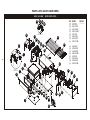
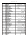
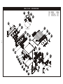
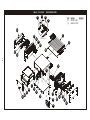
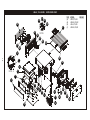
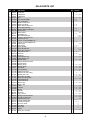
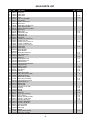
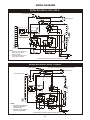
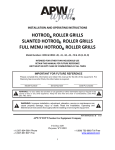
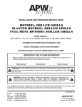
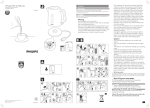
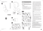
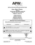
R
INSTALLATION AND OPERATING INSTRUCTIONS
HOTROD R ROLLER GRILLS
SLANTED HOTROD R ROLLER GRILLS
FULL MENU HOTROD R ROLLER GRILLS
Model Numbers: HR & HRS -31, -50, -45, -75 & -85 (BC, BD, BW, S, SBC, SBD, SBW)
INTENDED FOR OTHER THAN HOUSEHOLD USE
RETAIN THIS MANUAL FOR FUTURE REFERENCE
UNIT MUST BE KEPT CLEAR OF COMBUSTIBLES AT ALL TIMES
IMPORTANT FOR FUTURE REFERENCE
Please complete this information and retain this manual for the life of the equipment. For
Warranty Service and/or Parts, this information is required.
Model Number
!
Serial Number
Date Purchased
WARNING: For your safety do not store or use gasoline or other flammable vapors or liquids in the
vicinity of this or any other appliance. Keep the area free and clear of combustibles. (See ANZI
Z83.14B, 1991)
!
WARNING: Improper installation, adjustment, alteration, service or maintenance can
cause property damage, injury or death. Read the Installation, Operating and
Maintenance Instructions thoroughly before installing or servicing this equipment.
!
!
This equipment has been engineered to provide you with year-round dependable service when used
according to the instructions in this manual and standard commercial kitchen practices.
P/N 8893920 10/08
Phone:
Fax:
Toll Free:
Website:
E-mail:
+1 (307) 634-5801
+1 (307) 637-8071
+1 (800) 752-0863
www.apwwyott.com
[email protected]
APW WYOTT
P.O. Box 1829
Cheyenne, WY 82003
1
APW Wyott takes pride in the design and quality of our products. When used as intended and with proper
care and maintenance, you will experience years of reliable operation from this equipment. To ensure best
results, it is important that you read and follow the instructions in this manual carefully.
Installation and start-up should be performed by a qualified installer who thoroughly read, understands and
follows these instruction.
If you have questions concerning the installation, operation, maintenance or service of this product, write
Technical Service Department APW/Wyott Foodservice Equipment Company, P.O. Box 1829, Cheyenne,
WY 82003.
SAFETY PRECAUTIONS
Before installing and operating this equipment be sure everyone involved in its operation are fully trained
and are aware of all precautions. Accidents and problems can result by a failure to follow fundamental rules
and precautions.
The following words and symbols, found in this manual, alert you to hazards to the operator, service
personnel or the equipment. The words are defined as follows:
!
DANGER: This symbol warns of imminent hazard which will result in serious injury or death.
!
!
WARNING: This symbol refers to a potential hazard or unsafe practice, which could result in
serious injury or death.
!
!
CAUTION: This symbol refers to a potential hazard or unsafe practice, which may result in minor or
moderate injury or product or property damage.
!
!
NOTICE: This symbol refers to information that needs special attention or must be fully understood
even though not dangerous.
!
!
CAUTION: These models are designed, built, and sold for commercial use. If these models are
positioned so the general public can use the equipment make sure that cautions, warnings, and
operating instructions are clearly posted near each unit so that anyone using the equipment will
use it correctly and not injure themselves or harm the equipment.
!
!
WARNING: SHOCK HAZARD - Do not open any panels that require the use of tools.
!
!
WARNING: Improper installation, adjustment, alteration, service or maintenance can cause
property damage, injury or death. Read the Installation, Operating and Maintenance Instructions
thoroughly before installing or servicing this equipment.
!
!
NOTICE: The unit when installed, must be electrically grounded and comply with local codes, or in
the absence of local codes, with the national electrical code ANSI/NFPA70- latest edition.
Canadian installation must comply with CSA-STANDARD C.22.2 Number 0 M1982 General
Requirements-Canadian Electrical Code Part II, 109-M1981- Commercial Cooking Appliances.
!
!
NOTICE: Local codes regarding installation vary greatly from one area to another. The National
Fire Protection Association, Inc. states in its NFPA96 latest edition that local codes are “Authority
Having Jurisdiction” when it comes to requirement for installation of equipment. Therefore,
installation should comply with all local codes.
!
2
WARNING: Check the data plate on this unit before installation. Connect the unit only to the voltage
and frequency listed on the data plate. Connect only to 1 or 3 phase as listed on the data plate.
!
!
WARNING: Disconnect device from electrical power supply and place a Tag Out-Lockout on the
power plug, indicating that you are working on the circuit.
!
!
CAUTION: Maintenance & repair should be handled by a factory authorized agent. Before doing
any maintenance or repair, contact APW Wyott.
!
!
NOTICE: Install according to the spacing requirements listed in the installation section of
this manual. We strongly recommend having a competent professional install this
equipment. A licensed electrician should make the electrical connections and connect
power to the unit. Local codes should always be used when connecting these units to
electrical power. In the absence of local codes, use the latest version of the National
Electrical Code.
!
!
CONTENTS
Description
Safety Precautions
Specifications
General Installation Instructions
Installation
Operation
Cleaning
Service
Parts Lists & Exploded Views
HR-31 & 50 BW (Exp View)
HR-31 & 50 BC (Exp View)
HR-31 & 50 (Exp View)
Page
Description
2
4
5
6
6
6
7
8
8
9
10
HR-31 (Parts List)
HR-50 (Parts List)
HR-45, 75 & 85 (Exp View)
HR-45, 75 & 85 BC
HR-45, 75 & 85 BW
HR-45 (Parts List)
HR-75 (Parts List)
HR-85 (Parts List)
Wiring Diagrams
Warranty
Page
11
12
13
14
15
16
17
18
19
20
LOCATION OF DATA PLATE
The data plate for the Hot Rod is located on the back of the unit.
IMMEDIATELY INSPECT FOR SHIPPING DAMAGE
All containers should be examined for damage before and during unloading. The freight carrier has
assumed responsibility for its safe transit and delivery. If equipment is received damaged, either apparent
or concealed, a claim must be made with the delivering carrier.
A) Apparent damage or loss must be noted on the freight bill at the time of delivery. It must then be signed
by the carrier representative (Driver). If this is not done, the carrier may refuse the claim. The carrier can
supply the necessary forms.
B) Concealed damage or loss if not apparent until after equipment is uncrated, a request for inspection
must be made to the carrier within 15 days. The carrier should arrange an inspection. Be certain to hold all
contents and packaging material.
Installation and start-up should be performed by a qualified installer who thoroughly read, understands and
follows these instructions.
3
SPECIFICATIONS
MODEL
HR-31
HR-31BC
HR-31BD
HR-31BW
HRS-31
HRS-31BC
HRS-31BD
HRS-31BW
HR-31S
HR-31SBC
HR-31SBD
HR-31SBW
HRS-31S
HRS-31SBC
HRS-31SBD
HRS-31SBW
HR-50
HR-50BC
HR-50BD
HR-50BW
HRS-50
HRS-50BC
HRS-50BD
HRS-50BW
HR-50S
HR-50SBC
HR-50SBD
HR-50SBW
HRS-50S
HRS-50SBC
HRS-50SBD
HRS-50SBW
HR-45
HR-45BC
HR-45BW
HRS-45BC
HRS-45BW
HR-75
HR-75BC
HR-75BW
HRS-75BC
HRS-75BW
HR-85BW
HRS-85BW
HR-31
WIDTH
DEPTH
HEIGHT
VOLTAGE
AMPS
23.75"
23.75"
23.75"
23.75"
23.75"
23.75"
23.75"
23.75"
23.75"
23.75"
23.75"
23.75"
23.75"
23.75"
23.75"
23.75"
34.75"
34.75"
34.75"
34.75"
34.75"
34.75"
34.75"
34.75"
34.75"
34.75"
34.75"
34.75"
34.75"
34.75"
34.75"
34.75"
23.75"
23.75"
23.75"
23.75"
23.75"
34.75"
34.75"
34.75"
34.75"
34.75"
34.75"
34.75"
23.75"
18.625"
18.625"
18.625"
18.625"
18.625"
18.625"
18.625"
18.625"
18.375"
18.375”
18.375”
18.375”
18.375"
18.375”
18.375”
18.375”
18.625"
18.625"
18.625"
18.625"
18.625"
18.625"
18.625"
18.625"
18.375"
18.375”
18.375”
18.375”
18.375"
18.375”
18.375”
18.375”
29.56"
29.56"
29.56"
29.56"
29.56"
29.56"
29.56"
29.56"
29.56"
29.56"
29.56"
29.56"
18.625"
9.125"
13.1875"
13.1875"
13.1875"
9.125"
13.1875"
13.1875"
13.1875"
11.75"
16.125"
16.125"
16.125"
11.75"
16.125"
16.125"
16.125"
9.125"
13.1875"
13.1875"
13.1875"
9.125"
13.1875"
13.1875"
13.1875"
11.75"
16.125"
16.125"
16.125"
11.75"
16.125"
16.125"
16.125"
10.875"
13.75"
13.75"
13.75"
13.75"
10.875"
16.75"
16.75"
16.75"
16.75"
16.75"
16.75"
9.125"
120
120
120
120
120
120
120
120
120
120
120
120
120
120
120
120
120
120
120
120
120
120
120
120
120
120
120
120
120
120
120
120
120
120
120
120
120
120
120
120
120
120
120
120
208/240
8.3
8.3
8.3
8.3
8.3
8.3
8.3
8.3
8.3
8.3
8.3
8.3
8.3
8.3
8.3
8.3
11
11
11
11
11
11
11
11
11
11
11
11
11
11
11
11
12.2
12.2
12.2
12.2
12.2
16.6
16.6
16.6
16.6
16.6
18.7
18.7
3.2/4.8
4
GENERAL INSTALLATION INSTRUCTIONS
This unit has been inspected and tested at the factory prior to shipment.
Unpack the unit and remove all packing materials. Place on a flat horizontal surface at the desired location.
!
!
!
WARNING: Check the data plate on this unit before installation. Connect the unit only to the voltage
and frequency listed on the data plate. Connect only to 1 or 3 phase as listed on the data plate.
!
WARNING: IMPROPER GROUNDING COULD RESULT IN ELECTRICAL SHOCK! This
appliance is equipped with a three prong (grounded) plug for your protection against electrical
shock hazard and should be plugged directly into a properly grounded three prong receptacle.
Do not cut or remove the grounding prong from this plug.
!
CAUTION: Do not use ordinary steel wool as any particles left on the surface will rust.
!
NEVER USE a wire brush, steel or abrasive scouring pads (except stainless), scraper, file or other steel
tools. Surfaces which are marred collect dirt more rapidly and become more difficult to clean. Marring also
increases the possibility of corrosive attack.
NEVER use any corrosive cleaner. Use only cleaners approved for stainless steel.
NEVER use cleaning solvents with a hydrocarbon base.
GENERAL INSTALLATION:
1.
2.
3.
4.
Always clean equipment thoroughly before first use. (See general cleaning instructions)
Check ratings label for your model designation and electrical ratings.
For best results, use stainless steel countertops.
Attach legs to unit.
GENERAL OPERATION INSTRUCTIONS:
1.
2.
3.
4.
Trained personnel should operate all food service equipment.
Do not allow your customers to come into contact with any surface labeled "CAUTION HOT".
Where applicable, never pour cold water into dry heated units.
Where applicable, do not cook, warm or hold food directly in liner/well pans. Always use steam table
pans/inserts, etc.
5. NEVER hold food below 140° F.
GENERAL CLEANING INSTRUCTIONS:
1. Never clean any electrical unit by immersing it in water. Turn the unit off and allow it to cool before
surface cleaning.
2. Always clean equipment thoroughly before first use. Clean unit daily. Except where noted on charts:
use warm, soapy water. Mild cleansers and plastic scouring pads may be used to remove baked-on
food and water scale on metal unit. NOTE: do not clean roller tubes with abrasive cleaners or
scouring pads. Follow instructions on page 6.
3. Unplug electrical unit before cleaning or servicing. All service should be performed by an APW
Wyott authorized service agency.
GENERAL TROUBLESHOOTING:
Always ask and check:
1. Is the unit connected to a live power source?
2. Check the circuit breaker.
5
3. Is power switch on and pilot light glowing?
4. Check the rating label. Are you operating unit on the proper voltage?
If the above checks out and you still have problems, call an APW Wyott authorized service agency.
INSTALLATION
Place the HOTROD R directly on a countertop or on a matching APW Wyott Bun Warmer or Bun Cabinet
(available separately). Place the unit close to an AC outlet, of the correct voltage, to avoid undue strain on
the power cord.
CAUTION: To avoid equipment damage, make certain that the nameplate voltage is the same as the outlet
voltage.
If the plug is to be removed and replaced with a plug more suitable for your area, the color code for the
power cable is:
Neutral (N) = White or Blue
Live (l) = Black or Brown Safety Earth (E) = Green or Yellow/Green
After a suitable location has been chosen, wipe the rollers and the drip pan with a damp cloth. The unit is
ready for use.
OPERATION
!
WARNING: This unit is not intended to hold potentially hazardous foods such as un-cooked or unpreserved meats and sausages.
!
There are three simple controls on the front of this unit: a switch, which controls the tube rotation, and two
adjustable heat controls, which activates the two banks of heating elements in the roller tubes. Both heat
controls have a light above them indicating either "Front' or "Back". The front heat control activates the first
5 or 6 (depending on if your unit has 1 0 or 11 tubes). The back Control activates the remaining 5 tubes.
Each bank of tubes can be heated independently of the others and at separate temperature settings.
Variations in voltage and ventilation make experimenting the best guide to power level adjustment.
When a preferred adjustment is found, and it is desired to return consistently to the same spot on the
controls, the controls can be fine-tuned by aligning with a mark on the knob. This adjustment does not
require a service visit.
CLEANING
DAILY CLEANING INSTRUCTIONS:
1. Heat the unit.
2. Using a moist cloth filled with crushed or flaked ice, wipe each tube. Wipe the tubes from each end to
the center. This will keep as much of the loosened particles out of the bearings as possible. Extend
the cloth as far as possible between the rollers.
3. With the heated rollers wiped with an ice filled cloth to loosen the particles, now, wipe clean with
another cloth. Continue to wipe from the end of the rollers to the center. This will reduce the grease
and partials getting into the bearings and drive mechanism. This will extend the life of the unit and
extend the period between routine maintenance of the drive mechanism.
CAUTION: NEVER use abrasive powders or pads; these cleaners may damage the roller finish. Also, the
particles may get into the drive mechanism shortening the unit life.
4. Remove the drip pan and wash it in hot, soapy water, then rinse.
5. If stains are still present, add a light detergent to the cloth and repeat.
6. Replace the pan and turn the unit off if the grill will not be immediately used.
6
Alternate Cleaning Method using optional 3M sponge (#21807305) and cleaning handle (#21807300):
1. Turn heat down to lower setting (i.e. "hold" temperature) and allow grill to cool.
2. If the grill has considerable grease build-up, wipe the excess grease from the rollers with a lint free
towel or paper towel before using the soap and sponge.
3. Place sponge onto cleaning handle.
4. Immerse sponge in warm, soapy water.
5. Scrub rollers starting from the outside of the roller working your way to the center. Rinse sponge and
re-wet with the soapy solution as needed.
6. Ensure that entire roller surface is cleaned.
7. Dry with a lint free towel or paper towel.
NOTE: Cleanup will be faster if the product is specifically made for cooking on roller grills. Several meat
packers now offer this product.
For high-volume applications or for products that have a high sugar or fat content. the HOTROD R may
require more frequent cleaning. For longer life of your HOTROD R , follow instructions for periodic cleaning
throughout the day.
PERIODIC CLEANING THROUGHOUT THE DAY:
1. For high-volume applications or for product that has a high fat content clean the rollers every 3-4
hours.
2. Clean by removing the product from the rollers and wiping with a damp cloth from outside end of
the rollers to the center. Replace the product and continue cooking. There should be no need to turn
off the heat when wiping down the rollers. But care should be taken not to bring hands into direct
contact with the rollers as a burn could result.
NOTE: THIS APPLIANCE SHALL NOT BE CLEANED WITH A WATER JET.
SERVICE
Service work should be performed only by a qualified technician who is experienced in and knowledgeable
with the operation of commercial gas, electric, steam cooking equipment. Contact the Authorized Service
Agency for reliable service, dependable advice or other assistance and for genuine factory parts.
IF THE SUPPLY CORD IS DAMAGED, IT MUST BE REPLACED BY THE MANUFACTURER OR ITS
SERVICE AGENT OR A SIMILARLY QUALIFIED PERSON IN ORDER TO AVOID A HAZARD.
NOTES:
7
PARTS LISTS & EXPLODED VIEWS
HR-31 & 50 BW
37 38
36 37
38
36
20
20
21
21
(EXPLODED VIEW)
39
39
DETAIL H
22
22
22
24
24
23
23
27
27
28
28
25
25
8
44
44
66
(A)
(B)
(C)
(D)
(E)
(F)
(G)
(H)
26
26
11
DETAIL E 77
88
120V
(A)
(B)
(C)
(D)
(E)
(F)
(G)
(H)
32
32
55
42
42
E
H
11
11
33 15
15
99
16
16
12
12
17
17
13
13
14
14
40
40
41
41
MODEL
208/240V
HR-31 BW
HRS-31 BW
HR-31 SBW
HRS-31 SBW
HR-31 BD
HRS-31BD
HR-31 SBD
HRS-31 SBD
HR-50 BW
HRS-50 BW
HR-50 SBW
HRS-50 SBW
HR-50 BD
HRS-50 BD
HR-50 SBD
HRS-50 SBD
35
35
33
33
34
34
HR-31 & 50 BC
37
37 38
38
36
36
20
20
21
21
22
22
EXPLODED VIEW
120V
(I)
(J)
(K)
(L)
39
39
27
27
DETAIL E
24
24
23
23
(I)
(J)
(K)
(L)
28
28
25
25
HR-50 BC
HRS-50 BC
HR-50 SBC
HRS-50 SBC
26
26
9
32
32
42
42
22
E
45
45
46
46
47
47
48
48
33
15
15
16
16
17 40
17
40
12
12
13
13
14
14
41
41
35
35
33
33
MODEL
208/240V
HR-31 BC
HRS-31 BC
HR-31 SBC
HRS-31 SBC
34
34
HR-31 & 50
36
36
20
20
21
21
22
22
24
24
23
23
37
37
38
38
EXPLODED VIEW
39
39
DETAIL C
27
27
26
26
25
25
28
28
33
33
120V
(M)
(N)
(O)
(P)
(GG)
(HH)
MODEL
208/240
HR-31
(CC)
HRS-31
(DD)
HR-31S
(EE)
HRS-31S
(FF)
HR-31SR
HRS-31SR (JJ)
120V
(M)
(N)
(O)
(P)
(GG)
(HH)
MODEL
208/240
HR-50
(CC)
HRS-50
(DD)
HR-50S
(EE)
HRS-50S
(FF)
HR-50SR
HRS-50SR
34
34
10
44
44
41
41
16
16
17
17
35
35
22
15
15
42
42
33
C
12
12
13
13
14
14
40
40
HR-31 PARTS LIST
Item
P/N
1
2
2
3
5
6
7
8
9
9
11
12
12
13
13
14
14
14
14
15
15
16
16
16
17
18
18
19
19
20
20
21
21
21
22
22
22
22
22
23
24
25
26
27
27
28
28
32
32
33
33
34
34
35
35
36
37
38
39
40
41
42
43
44
44
45
46
47
48
1481510
1327900
1328200
8705610
21794621
2421600
21794619
21834618
1431101
1431113
8641500
21807405
21771411
8967400
8968900
1542002
1532500
1542005
782068
1331800
47591400
21808154
21807654
8815600
1513903
21797415
21749502
21797414
21749503
21833914
21747001
21794611
21748100
21795111
21794609
21748000
21794609
21795109
21771025
21793400
21748900
422300
21771412
21771429
21771418
1431532
1431533
1212000
1211700
21748303
21771016
21748312
21771017
21748505
21748511
21792309
21792308
21748501
8414700
8662100
8966400
21748510
21750710
21838116
21750700
8702000
21794643
21749953
8705000
Description
Qty
Thermostat
Infinite Switch
Infinite Switch
Knob
Pan, Cover
Pan, 2/3 6" Deep
Weldm't, Drawer Frame
Drawer, Front HR-31
Heater, Rope 200W 120V
Heater, Rope 200W 208V
Bearings, Stainless Roller Slides
Bottom, HR-31
Bottom, HR-31
Strain Relief Right Angle
Strain Relief Right Angle
Cordset, 5-15P 14/3 90C SJO
Cordset, SJTO 16-3
Cordset, 14/3 500C W/NEMA 6-15P
Cordset, 12/3 SJTOW NEMA 5-20P
Switch Rocker
Switch Rocker
Decal, HR-31 & 45BW
Decal, HR-31BD & BC
Decal, HR-31 Front Panel
Light, Indicator, 250V
Panel, End L.H. Slant
Panel, Left Slant HR
Panel, End R.H. Slant
Panel, Right Slant HR
Panel, End
Panel, End
Heater Retainer, Front
Heater Retainer, Front
Heater Retainer, Front Slant
Element Support
Support, Element
Support, Element
Support, Element Slant
Support, Element Slant
Bearing, Hot Rod
Bearing, Hot Rod
Seal, Grease
Pan, Drip HR-31
Roller Tube-31 Plated
Roller Tube-31 Xylan Coating
Element, HR-31 120V
Element, HR-31 220V, 115W
Motor, Gear 110V, 60HZ
Motor, Gear 240V 50-60HZ
Chain Guide Bracket
Chain Guide Bracket
Bracket, Gage
Bracket, Gage
Chain
Chain Drive HR Slant, Wide Spacing
Tensioner
Bushing
Sprocket
Nut #10-32
Leg, 1" Chrome
Bushing, Snap HEYCO #2820
Sprocket, 17 Tooth w/Hub
Insulation, Leftside CHAIO TAI HR
Insulation, HR
Insulation, HR Motor Side
Knob, 8-32 Thread
Door, BC-31
Plate, Strike
Magnet
1
2
2
2
1
1
1
1
1
1
4
1
1
1
1
1
1
1
1
1
1
1
1
1
1
1
1
1
1
2
2
1
1
1
1
1
1
1
1
4
V.
V.
1
V.
V.
V.
V.
1
1
1
1
1
1
1
1
1
1
1
1
4
V.
1
1
2
1
1
1
1
1
11
Used On
ABCD
ABCDE FGH I J K LMNOP
GG HH JJ
CC DD EE FF
A B C D E F G H I J K L M N O P CC DD EE FF GG HH JJ
ABCDE FGH
ABCDE FGH
ABCDE FGH
ABCD
ABCDE FGH
ABCDE FGH I J K L
M N O P CC DD EE FF GG HH JJ
ABCDE FGH I J K L
M N O P CC DD EE FF GG HH JJ
MNOP
GG HH JJ
ABCDE FGH I J K L
CC DD EE FF
M N O P CC DD EE FF
ABCDE FGH I J K L
ABCD
E FGH I J K L
GG HH JJ
M N O P CC DD EE FF GG HH JJ
ABCDE FGH I J K L
CD
GH
K L
CD
GH
OP
EE FF
JJ
OP
EE FF
JJ
K L
AB
E F
I J
AB
E F
I J
MN
CC DD
CC DD
GG HH
GG HH
GG HH JJ
MNOP
CD
GH
AB
E F
AB
E F
K L
EE FF
MN
CD
A
A
A
A
A
B
B
B
B
C
C
C
C
C
D
D
D
D
GH
E
E
E
E
E
CC DD
GH
GH
GH
GH
G
B D F H
ABCDE FGH
F
F
F
F
K L
I
I
I
I
I
J
J
J
J
K
K
K
K
K
L
L
L
L
MN
MN
MN
MN
M
J L N
I J K LMN
O
O
O
O
O
O
E F
CD
AB
E F
CD
AB
A
A
A
A
A
A
A
B
B
B
B
B
B
B
I J
GH
I J
GH
E F
C
C
C
C
C
C
C
C
D
D
D
D
D
D
D
D
E
E
E
E
E
E
E
F
F
F
F
F
F
F
MN
K L
GH
GH
GH
GH
GH
GH
GH
GH
O
MN
K L
I J
I
I
I
I
I
I
I
J
J
J
J
J
J
J
O
MN
K
K
K
K
K
K
K
K
L
L
L
L
L
L
L
L
MN
MN
MN
MN
MN
MN
MN
MN
P
P
P
P
P
P
OP
ABCDE FGH I J K LMNO
AB
GG HH
I J
O
O
O
O
O
O
O
O
O
CC
CC
CC
CC
CC
DD
DD
DD
DD
EE
EE
EE
EE
EE
EE
FF
FF
FF
FF
FF
GG
GG
GG
GG
FF GG
GG
CC DD EE FF
P
GG
CC DD EE FF
CC DD
GG
P
EE FF
GG
P
CC DD
GG
P
EE FF
P CC DD EE FF GG
P CC DD EE FF GG
P CC DD EE FF GG
P CC DD EE FF GG
P
GG
P CC DD EE FF GG
P CC DD EE FF GG
P CC DD EE FF GG
HH
HH
HH
HH
HH
JJ
JJ
JJ
JJ
JJ
JJ
DD
HH JJ
HH JJ
HH
JJ
HH
JJ
HH
HH
HH
HH
HH
HH
HH
HH
HH
JJ
JJ
JJ
JJ
JJ
JJ
JJ
JJ
JJ
ABCDE FGH I J K L
M N O P CC DD EE FF GG HH JJ
I
I
I
I
J
J
J
J
K
K
K
K
L
L
L
L
HR-50 PARTS LIST
Item
P/N
1
2
2
3
5
6
7
8
9
9
11
12
12
13
13
14
14
14
14
15
15
16
16
16
17
18
18
19
19
20
20
21
21
21
22
22
22
22
22
23
24
25
26
27
27
28
28
32
32
33
33
34
34
35
35
36
37
38
39
40
41
42
43
44
44
45
46
47
48
1481510
1327900
1328200
8705610
21794621
2421600
21794619
21834618
1431101
1431113
8641500
21807405
21771411
8967400
8968900
1542002
1532500
1542005
782068
1331800
47591400
21808154
21807654
8815600
1513903
21797415
21749502
21797414
21749503
21833914
21747001
21794611
21748100
21795111
21794609
21748000
21794609
21795109
21771025
21793400
21748900
422300
21771412
21771429
21771418
1431532
1431450
1212000
1211700
21748303
21771016
21748312
21771017
21748505
21748511
21792309
21792308
21748501
8414700
8662100
8966400
21748510
21750710
21838116
21750700
8702000
21794643
21749953
8705000
Description
Qty
Thermostat
Infinite Switch
Infinite Switch
Knob
Pan, Cover
Pan, 2/3 6" Deep
Weldm't, Drawer Frame
Drawer, Front HR-50
Heater, Rope 200W 120V
Heater, Rope 200W 208V
Bearings, Stainless Roller Slides
Bottom, HR-50
Bottom, HR-50
Strain Relief Right Angle
Strain Relief Right Angle
Cordset, 5-15P 14/3 90C SJO
Cordset, SJTO 16-3
Cordset, 14/3 500C W/NEMA 6-15P
Cordset, 12/3 SJTOW NEMA 5-20P
Switch Rocker
Switch Rocker
Decal, HR-31 & 45BW
Decal, HR-50BD & BC
Decal, HR-50 Front Panel
Light, Indicator, 250V
Panel, End L.H. Slant
Panel, Left Slant HR
Panel, End R.H. Slant
Panel, Right Slant HR
Panel, End
Panel, End
Heater Retainer, Front
Heater Retainer, Front
Heater Retainer, Front Slant
Element Support
Support, Element
Support, Element
Support, Element Slant
Support, Element Slant
Bearing, Hot Rod
Bearing, Hot Rod
Seal, Grease
Pan, Drip HR-50
Roller Tube-50 Plated
Roller Tube-50 Xylan Coating
Element, HR-50 120V
Element, HR-50 220V, 115W
Motor, Gear 110V, 60HZ
Motor, Gear 240V 50-60HZ
Chain Guide Bracket
Chain Guide Bracket
Bracket, Gage
Bracket, Gage
Chain
Chain Drive HR Slant, Wide Spacing
Tensioner
Bushing
Sprocket
Nut #10-32
Leg, 1" Chrome
Bushing, Snap HEYCO #2820
Sprocket, 17 Tooth w/Hub
Insulation, Leftside CHAIO TAI HR
Insulation, HR
Insulation, HR Motor Side
Knob, 8-32 Thread
Door, BC-50
Plate, Strike
Magnet
1
2
2
2
1
1
1
1
1
1
4
1
1
1
1
1
1
1
1
1
1
1
1
1
1
1
1
1
1
2
2
1
1
1
1
1
1
1
1
4
V.
V.
1
V.
V.
V.
V.
1
1
1
1
1
1
1
1
1
1
1
1
4
V.
1
1
2
1
1
1
1
1
12
Used On
ABCD
ABCDE FGH I J K LMNOP
GG HH
CC DD EE FF
A B C D E F G H I J K L M N O P CC DD EE FF GG HH
ABCDE FGH
ABCDE FGH
ABCDE FGH
ABCD
ABCDE FGH
ABCDE FGH I J K L
M N O P CC DD EE FF GG HH
ABCDE FGH I J K L
M N O P CC DD EE FF GG HH
MNOP
GG HH
ABCDE FGH I J K L
CC DD EE FF
M N O P CC DD EE FF
ABCDE FGH I J K L
ABCD
E FGH I J K L
GG HH
M N O P CC DD EE FF GG HH
ABCDE FGH I J K L
CD
GH
K L
CD
GH
OP
EE FF
OP
EE FF
K L
AB
E F
I J
AB
E F
I J
MN
CC DD
CC DD
GG HH
GG HH
GG HH
MNOP
CD
GH
AB
E F
AB
E F
K L
EE FF
MN
CD
A
A
A
A
A
B
B
B
B
C
C
C
C
C
D
D
D
D
GH
E
E
E
E
E
CC DD
GH
GH
GH
GH
G
B D F H
ABCDE FGH
F
F
F
F
K L
I
I
I
I
I
J
J
J
J
K
K
K
K
K
L
L
L
L
MN
MN
MN
MN
M
J L N
I J K LMN
O
O
O
O
O
O
E F
CD
AB
E F
CD
AB
A
A
A
A
A
A
A
B
B
B
B
B
B
B
I J
GH
I J
GH
E F
C
C
C
C
C
C
C
C
D
D
D
D
D
D
D
D
E
E
E
E
E
E
E
F
F
F
F
F
F
F
MN
K L
MN
I J
GH
GH
GH
GH
GH
GH
GH
GH
O
K L
I
I
I
I
I
I
I
J
J
J
J
J
J
J
O
MN
K
K
K
K
K
K
K
K
L
L
L
L
L
L
L
L
MN
MN
MN
MN
MN
MN
MN
MN
P
P
P
P
P
P
OP
ABCDE FGH I J K LMNO
AB
GG HH
I J
O
O
O
O
O
O
O
O
O
CC
CC
CC
CC
CC
DD
DD
DD
DD
EE
EE
EE
EE
EE
EE
FF
FF
FF
FF
FF
GG
GG
GG
GG
FF GG
GG
CC DD EE FF
P
GG
CC DD EE FF
CC DD
GG
P
EE FF
GG
P
CC DD
GG
P
EE FF
P CC DD EE FF GG
P CC DD EE FF GG
P CC DD EE FF GG
P CC DD EE FF GG
P
GG
P CC DD EE FF GG
P CC DD EE FF GG
P CC DD EE FF GG
HH
HH
HH
HH
HH
DD
HH
HH
HH
HH
HH
HH
HH
HH
HH
HH
HH
HH
HH
ABCDE FGH I J K L
M N O P CC DD EE FF GG HH
I
I
I
I
J
J
J
J
K
K
K
K
L
L
L
L
HR-45, 75 & 85
37
37
36
36
20
20
21
21
22
22
EXPLODED VIEW
38
38
120V
(M)
(N)
39
39
27
27
DETAIL D
24
24
23
23
28
28
25
25
33
33
MODEL
208/240
HR-45,75,85
(CC)
HRS-45,75,85 (DD)
34
34
13
26
26
44
44
32
32
49
49
16
16
42
42
15
15
17
17
33
22
12
12
41
41
14
14
13
13
40
40
D
35
35
HR-45, 75 & 85 BC
37
37
36
36
EXPLODED VIEW
38
38
120V
(I)
(J)
39
39
20
20
23
23
21
21
24
24
27
27
DETAIL A
25
25
28
28
49
49
26
26
22
22
14
32
32
22
45
45
46
46
47
47
48
48
33
15
15
A
16
16
12
12
17
17
13
13
14
14
40
40
42
42
41 35
35
41
33
33
34
34
MODEL
208/240V
HR-45, 75, BC
HRS-45, 75, BC
HR-45, 75 & 85 BW
36
36
20
20
23
23
21
21
24
24
37
37
EXPLODED VIEW
38
38
39
39
120V
(A)
(B)
(E)
(F)
27
27
DETAIL I
25
25
49
49
26
26
22
22
22
28
28
15
11
55
66
DETAIL H
88
32
32
H
77
11
11
99
15
15
I
33
16
16
12
12
17
17
13
13
14
14
40
40
41
41
42
42
35
35
33
33
34
34
MODEL
HR-45, 75, BW
HRS-45, 75, BW
HR-45, 75, BD
HRS-45, 75, BD
208/240V
HR-45 PARTS LIST
Item
P/N
1
2
2
3
5
6
7
8
9
9
11
12
12
13
13
14
14
14
14
15
15
16
16
16
17
20
20
21
21
22
22
22
23
24
25
26
27
27
28
32
32
33
33
34
34
35
36
37
38
39
40
41
42
43
44
44
45
46
47
48
49
1481510
1327900
1328200
8705610
21794821
2420200
21794619
21794818
1431102
1431113
8641500
21807805
21771421
8967501
8968900
1542002
1532500
1542005
782068
1331800
47591400
21808154
21807654
8815600
1513903
21807814
21752487
21792239
21748100
21792234
21807888
21794609
21793400
21748900
422300
21771420
21771429
21771418
1431532
1212000
1211700
21792336
21771016
21748312
21771017
21792251
21792309
21792308
21748501
8414700
8662100
8966400
21748510
21750710
21807816
21807817
8702000
21794643
21749953
8705000
1212300
Description
Qty Used On
Thermostat
Infinite Switch
Infinite Switch
Knob
Pan, Cover HR-45BWE
Pan, 12x20x6 Deep
Weldm't, Drawer Frame
Drawer, Front HR-45
Heater, Rope, 84" 300W 120V
Heater, Rope 200W 208V
Bearings, Stainless Roller Slides
Bottom, HR-45
Bottom, HR-45
Strain Relief 12/3
Strain Relief Right Angle
Cordset, 5-15P 14/3 90C SJO
Cordset, SJTO 16-3
Cordset, 14/3 500C W/NEMA 6-15P
Cordset, 12/3 SJTOW NEMA 5-20P
Switch Rocker
Switch Rocker
Decal, HR-45BW
Decal, HR-31BD & BC
Decal, HR-31 Front Panel
Light, Indicator, 250V
Panel, End
Panel, End
Heater Retainer, Front
Heater Retainer, Front
Element Support
Support, Element Rope Heater
Support, Element
Bearing, Hot Rod
Bearing, Hot Rod
Seal, Grease
Pan, Drip HRS-45
Roller Tube-31 Plated
Roller Tube-31 Xylan Coating
Element, HR-31 120V
Motor, Gear 110V, 60HZ
Motor, Gear 240V 50-60HZ
Chain Guide Bracket
Chain Guide Bracket
Bracket, Gage
Bracket, Gage
Chain
Tensioner
Bushing
Sprocket
Nut #10-32
Leg, 1" Chrome
Bushing, Snap HEYCO #2820
Sprocket, 17 Tooth w/Hub
Insulation, HR-45-75-85
Insulation, HR Right Side
Insulation, HR Left Side
Knob, 8-32 Thread
Door, BC-31
Plate, Strike
Magnet
Motor, Gear 110V, 60HZ
1
2
2
2
1
1
1
1
1
1
4
1
1
1
1
1
1
1
1
1
1
1
1
1
1
2
2
1
1
1
1
1
4
V.
V.
1
V.
V.
V.
1
1
1
1
1
1
1
1
1
1
1
4
V.
1
1
1
1
1
1
1
1
1
16
A B
A B I J M N
A B I J M N
A B
A B
A B
A B
A B
A B I J
M N
A B
I J M N
I J M N
A B
M N
A B I J
A B
I J
M N
A B I J
A B I J
M N
A B I J M N
A B I J M N
A B I J M N
A B I J M N
A B I J M N
A B I J M N
A
I
B
M
J
N
A B I J M N
A B I J M N
A B I J M N
A B I J M N
A B I J M N
A B I J M N
A B I J M N
A B I J M N
A B I J M N
A B I J M N
A B I J M N
A B I J M N
M N
A B I J
A B I J
I J
I J
I J
I J
A B I J M N
HR-75 PARTS LIST
Item
P/N
1
2
2
3
5
6
7
8
9
9
11
12
12
13
13
13
13
14
14
14
14
14
15
15
16
16
16
17
20
20
21
21
22
22
22
23
24
25
26
27
27
28
32
32
33
33
34
34
35
36
37
38
39
40
40
41
42
43
44
44
45
46
47
48
49
49
1481510
1327900
1328200
8705610
21792221
2421401
21794619
21833918
1431105
1431113
8641500
21792205
21771461
8968900
8967500
8967501
8967400
1542002
1532500
1542005
1537000
782068
1331800
47591400
21808155
21807655
8816550
1513903
21807814
21752487
21792239
21748100
21792234
21807888
21794609
21793400
21748900
422300
21752488
21752380
21752370
1431550
1212000
1211700
21792336
21771016
21748312
21771017
21792251
21792309
21792308
21748501
8414700
8632000
8662100
8966400
21748510
21750715
21807816
21807817
8702000
21795618
21749953
8705000
1211800
1212300
Description
Qty
Thermostat
Infinite Switch
Infinite Switch
Knob
Pan, Cover HR-45BWE
Pan, Modified
Weldm't, Drawer Frame
Drawer, Front
Heater, Rope, 108" 400W 120V
Heater, Rope 200W 208V
Bearings, Stainless Roller Slides
Bottom Cover
Bottom Cover
Strain Relief 90 deg
Strain Relief 14/3
Strain Relief 12/3
Strain Relief
Cordset, 5-15P 14/3 90C SJO
Cordset, SJTO 16-3
Cordset, 14/3 500C W/NEMA 6-15P
Cordset, 14-3 NEMA 5-15P
Cordset, 12/3 SJTO W/NEMA 5-20P
Switch Rocker
Switch Rocker
Decal, HR-50BW
Decal, HR-50BC
Decal, HR-50 Front Panel
Light, Indicator, 250V
Panel, End
Panel, End
Heater Retainer, Front
Heater Retainer, Front
Element Support
Support, Element Rope Heater
Support, Element
Bearing, Hot Rod
Bearing, Hot Rod
Seal, Grease
Pan, Drip
Roller Tube-31 Plated
Roller Tube-31 Xylan Coating
Element, HR-50 120V
Motor, Gear 110V, 60HZ
Motor, Gear 240V 50-60HZ
Chain Guide Bracket
Chain Guide Bracket
Bracket, Gage
Bracket, Gage
Chain Drive 33-3/4" J36P
Tensioner
Bushing
Sprocket
Nut #10-32
Leg, 4" ADJ, 2000 lb Cap
Leg, 1" Chrome
Bushing, Snap HEYCO #2820
Sprocket, 17 Tooth w/Hub
Insulation, HR-45-75-85
Insulation, HR Right Side
Insulation, HR Left Side
Knob, 8-32 Thread
Bun Cabinet Door
Plate, Strike
Magnet
Motor, Gear 240V 50-60HZ
Motor, Gear 110V, 60HZ
1
2
2
2
1
1
1
1
1
1
4
1
1
1
1
1
1
1
1
1
1
1
1
1
1
1
1
1
2
2
1
1
1
1
1
4
V.
V.
1
V.
V.
V.
1
1
1
1
1
1
1
1
1
1
1
4
4
V.
1
1
1
1
1
1
1
1
1
1
17
Used On
A B
A B I J MN
CC DD
A B I J M N CC DD
A B
A B
A B
A B
A B
A B I J
M N CC DD
CC DD
A B
I J
MN
MN
CC DD
A B
I J
M N CC DD
A B I J
A B
I J
M
A B I J M
A B I J
M
A B I J M
CC DD
CC DD
A B I J M
CC DD
A
A
A
A
A
CC DD
CC DD
CC DD
CC DD
CC
DD
B
B
B
B
I
I
I
I
I
J
J
J
J
M
M
M
M
M
B
J
A B I J M
A B I J M
A B I J M
CC DD
CC DD
CC DD
CC DD
A B I J M
A
A
A
A
A
A
B
B
B
B
B
B
A B
A B
A B
A B
I
I
I
I
I
I
J
J
J
J
J
J
M
M
M
M
M
M
M
I J M
I J M
M
I J
I J
I J
I J
I J
I J
CC DD
CC DD
CC DD
CC DD
CC DD
CC DD
CC DD
CC DD
CC DD
CC DD
A B I J M
HR-85 PARTS LIST
Item
P/N
1
2
2
3
5
6
7
8
9
9
11
12
12
13
13
13
13
14
14
14
14
14
15
15
16
16
16
17
20
20
21
21
22
22
22
23
24
25
26
27
27
28
32
32
33
33
34
34
35
36
37
38
39
40
40
41
42
43
44
44
45
46
47
48
49
49
1481510
1327900
1328200
8705610
21792221
2421401
21794619
21833918
1431105
1431113
8641500
21792205
21771461
8968900
8967500
8967501
8967400
1542002
1532500
1542005
1537000
782068
1331800
47591400
21808155
21807655
8816550
1513903
21807814
21752487
21778135
21748100
21778134
21807888
21794609
21793400
21748900
422300
21752488
21752380
21752370
1431550
1212000
1211700
21832492
21771016
21748312
21771017
21748507
21792309
21792308
21748501
8414700
8632000
8662100
8966400
21748510
21750715
21807816
21807817
8702000
21795618
21749953
8705000
1211800
1212300
Description
Qty Used On
1
2
2
2
1
1
1
1
1
1
4
1
1
1
1
1
1
1
1
1
1
1
1
1
1
1
1
1
2
2
1
1
1
1
1
4
V.
V.
1
V.
V.
V.
1
1
1
1
1
1
1
1
1
1
1
4
4
V.
1
1
1
1
1
1
1
1
1
1
Thermostat
Infinite Switch
Infinite Switch
Knob
Pan, Cover HR-45BWE
Pan, Modified
Weldm't, Drawer Frame
Drawer, Front
Heater, Rope, 108" 400W 120V
Heater, Rope 200W 208V
Bearings, Stainless Roller Slides
Bottom Cover
Bottom Cover
Strain Relief 90 deg
Strain Relief 14/3
Strain Relief 12/3
Strain Relief
Cordset, 5-15P 14/3 90C SJO
Cordset, SJTO 16-3
Cordset, 14/3 500C W/NEMA 6-15P
Cordset, 14-3 NEMA 5-15P
Cordset, 12/3 SJTOW NEMA 5-20P
Switch Rocker
Switch Rocker
Decal, HR-50BW
Decal, HR-50BC
Decal, HR-50 Front Panel
Light, Indicator, 250V
Panel, End
Panel, End
Heater Retainer, Front
Heater Retainer, Front
Element Support
Support, Element Rope Heater
Support, Element
Bearing, Hot Rod
Bearing, Hot Rod
Seal, Grease
Pan, Drip
Roller Tube-31 Plated
Roller Tube-31 Xylan Coating
Element, HR-50 120V
Motor, Gear 110V, 60HZ
Motor, Gear 240V 50-60HZ
Chain Guide Bracket, HR-85
Chain Guide Bracket
Bracket, Gage
Bracket, Gage
Chain Drive 34-1/2" J38P
Tensioner
Bushing
Sprocket
Nut #10-32
Leg, 4" ADJ, 2000 lb Cap
Leg, 1" Chrome
Bushing, Snap HEYCO #2820
Sprocket, 17 Tooth w/Hub
Insulation, HR-45-75-85
Insulation, HR Right Side
Insulation, HR Left Side
Knob, 8-32 Thread
Bun Cabinet Door
Plate, Strike
Magnet
Motor, Gear 240V 50-60HZ
Motor, Gear 110V, 60HZ
18
CC DD
CC DD
CC DD
CC DD
CC DD
CC DD
CC DD
CC DD
CC DD
CC DD
CC DD
CC
CC
CC
CC
CC
DD
DD
DD
DD
DD
CC DD
CC DD
CC
CC
CC
CC
CC
DD
DD
DD
DD
DD
CC
CC
CC
CC
DD
DD
DD
DD
CC DD
WIRING DIAGRAMS
MODEL INCLUDE ALL HR-31 AND 50
(View with unit upside down, looking from the back.)
Use 11960-00 (2ea)
16
16
16
16
Power Light Ind
17
17
11
11
11 14
14
11
33
A
20
20
4
1
88
2
3
5
6
Thermostat
22
10
10
L1
PILOT
H1
H2
77
H2
L2
B
99
10
10
88
99
44
12
12
77
Pilot
Pilot
NOTE:
1. Omit wires & components in
section A for BC, BD &
standard models.
2. Omit wires & components in
section B for S models.
M
L2
L1
44
10
10
H1
10
10
B
3
PILOT
T-Stat Bulb
66
55
11
13
13
15
15
66
12
12
Front
13
13
17
17
Rear
14
14
Front Motor
20
20
10
10
10
10
10
10
10
10
55
Rear
Front
11
Crimp Terminal 11195-12 to Green Cordset Lead.
MODEL INCLUDE ALL HR-45, 75 AND 85
11960-00 (2ea)
(View with unit upside down, looking from the back.)
18
18
20
20
14
14
Power Light Ind
66
Front
19
19
17
17
17
17
11
11
M
14
11
11
A
20
20
15
15
33
13
13
12
12
4
1
Rear Motor
18
18
16
16
19
19
13
13
Use Item #10 (2ea)
88
16
16
5
6
2
3
Thermostat
B
55
11
T-Stat Bulb
22
M
44
12
12
L1
H2
L2
9
10
10
10
10
10
10
77
Pilot
Pilot
Front
10
10
11
Rear
Crimp Terminal 11195-12 to Green Cordset Lead.
19
5
Rear
PILOT
H1
H2
44
88
10
10
Front Motor
L1
77
99
L2
NOTE:
1. Omit wires & components in
section A for BC, BD &
standard models.
2. Add wires & components in
section B for 85 models.
10
10
PILOT
B
10
10
H1
66
33
10
10
APW WYOTT EQUIPMENT LIMITED WARRANTY
APW Wyott Foodservice Equipment Company warrants it's equipment against defects in materials and workmanship, subject to the
following conditions:
This warranty applies to the original owner only and is not assignable.
Should any product fail to function in its intended manner under normal use within the limits defined in this warranty, at the option of
APW Wyott such product will be repaired or replaced by APW Wyott or its Authorized Service Agency. APW Wyott will only be
responsible for charges incurred or service performed by its Authorized Service Agencies. The use of other than APW Wyott
Authorized Service Agencies will void this warranty and APW Wyott will not be responsible for such work or any charges associated
with same. The closest APW Wyott Authorized Service Agent must be used.
This warranty covers products shipped into the 48 contiguous United States, Hawaii, metropolitan areas of Alaska and Canada. There
will be no labor coverage for equipment located on any island not connected by roadway to the mainland.
Warranty coverage on products used outside the 48 contiguous United States, Hawaii, and metropolitan areas of Alaska and Canada
may vary. Contact the international APW Wyott distributor, dealer, or service agency for details.
Time Period
One year for parts and one year for labor, effective from the date of purchase by the original owner. The Authorized Service Agency
may, at their option, require proof of purchase. Parts replaced under this warranty are warranted for the un-expired portion of the
original product warranty only.
Exceptions
*Gas/Electric Cookline: Models GCB, GCRB, GF, GGM, GGT, CHP-H, EF, EG, EHP. Three (3) Year Warranty on all
component parts, except switches and thermostats. (2 additional years on parts only. No labor on second or third year.)
*Broiler Briquettes, Rock Grates, Cooking Grates, Burner Shields, Fireboxes: 90 Day Material Only. No Labor.
*Heat Strips: Models FD, FDL, FDD, FDDL. Two (2) Year Warranty on element only. No labor second year.
*Glass Windows, Doors, Seals, Rubber Seals, Light Bulbs: 90 Day Material Only. No Labor.
In all cases, parts covered by extended warranty will be shipped FOB the factory after the first year.
Portable Carry In Products
Equipment weighing over 70 pounds or permanently installed will be serviced on-site as per the terms of this warranty. Equipment
weighing 70 pounds or under, and which is not permanently installed, i.e. with cord and plug, is considered portable and is subject to
the following warranty handling limitations. If portable equipment fails to operate in its intended manner on the first day of
connection, or use, at APW Wyott's option or its Authorized Service Agency, it will be serviced on site or replaced.
From day two through the conclusion of this warranty period, portable units must be taken to or sent prepaid to the APW Wyott
Authorized Service Agency for in-warranty repairs. No mileage or travel charges are allowed on portable units after the first day of use.
If the customer wants on-site service, they may receive same by paying the travel and mileage charges. Exceptions to this rule: (1)
countertop warmers and cookers, which are covered under the Enhanced Warranty Program, and (2) toasters or rollergrills which have
in store service.
Exclusions
The following conditions are not covered by warranty:
*Equipment failure relating to improper installation, improper utility connection or supply and problems due to
ventilation.
*Equipment that has not been properly maintained, calibration of controls, adjustments, damage from improper cleaning
and water damage to controls.
*Equipment that has not been used in an appropriate manner, or has been subject to misuse or misapplication, neglect,
abuse, accident, alteration, negligence, damage during transit, delivery or installation, fire, flood, riot or act of god.
*Equipment that has the model number or serial number removed or altered.
If the equipment has been changed, altered, modified or repaired by other than an Authorized Service Agency during or after the
warranty period, then the manufacturer shall not be liable for any damages to any person or to any property, which may result from the
use of the equipment thereafter.
This warranty does not cover services performed at overtime or premium labor rates. Should service be required at times which
normally involve overtime or premium labor rates, the owner shall be charged for the difference between normal service rates and such
premium rates. APW Wyott does not assume any liability for extended delays in replacing or repairing any items beyond its control.
In all cases, the use of other than APW Wyott Authorized OEM Replacement Parts will void this warranty.
This equipment is intended for commercial use only. Warranty is void if equipment is installed in other than commercial application.
Water Quality Requirements
Water supply intended for a unit that has in excess of 3.0 grains of hardness per gallon (GPG) must be treated or softened before
being used. Water containing over 3.0 GPG will decrease the efficiency and reduce the operation life of the unit.
Note: Product failure caused by liming or sediment buildup is not covered under warranty.
“THE FOREGOING WARRANTY IS IN LIEU OF ANY AND ALL OTHER WARRANTIES EXPRESSED OR IMPLIED
INCLUDING ANY IMPLIED WARRANTY OF MERCHANTABILITY OR FITNESS FOR PARTICULAR PURPOSES
AND CONSTITUTES THE ENTIRE LIABILITY OF APW WYOTT. IN NO EVENT DOES THE LIMITED WARRANTY
EXTEND BEYOND THE TERMS STATED HEREIN.”
9/05
20