1
SUPPLEMENT to WI1004
The steps below supplement the WI1004 installation
instructions, continuing at step 6:
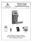
PDL6500
DL6500
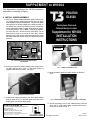
6. INSTALL INSIDE ASSEMBLY
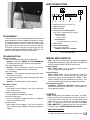
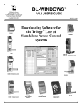
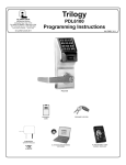
A. See Fig. A. Before installing the black plastic "inside housing", apply dielectric grease (provided) into all of the plugs
and sockets that are described below. Connect the ribbon
cable plug into its socket located on the inside housing circuit board, then connect the Auxiliary Power, Remote Release, and External Relay Contact plugs into their respective sockets shown in Fig. A. Note: These plugs and sockets fit only one way -- do not force any connections. Do not
allow wires to cross or lay on top of each other. Before
tightening any of the screws or bolts described below, jiggle
the ribbon cable and all other wiring to ensure wires are not
pinched.
AUXILIARY POWER AND
REMOTE RELEASE
EXTERNAL
RELAY
CONTACTS
The Keyless, Electronic
Network Mortise Lockset
Supplement to WI1004
INSTALLATION
INSTRUCTIONS
BATTERY PLUG FROM
CIRCUIT BOARD
RIBBON CABLE
PLUG FROM
BATTERY PACK
FIG. A: SOCKETS LOCATED IN THE INSIDE HOUSING
CIRCUIT BOARD
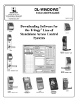
B. Secure the top of the "inside housing" to the inside mounting plate with two black 4-40 x ¼ flat head Phillips or
spanner head security screws. See Fig. B.
FIG. C: CONNECT THE BATTERY PLUGS
D. Insert the battery pack into inside housing as shown in
Fig. D.
FIG. B: SECURE TOP OF INSIDE HOUSING
C. Connect the battery pack plug to the circuit board battery
plug as shown in Fig. C. Note that upon connection of the
battery pack, you will hear three beeps.
ALARM LOCK SYSTEMS, INC.
A division of the Napco Security Technologies, Inc.
345 Bayview Avenue
Amityville, New York 11701
For Sales and Repairs 1-800-ALA-LOCK
For Technical Service 1-800-645-9440
FIG. D: INSERT BATTERY PACK INTO HOUSING ("SEALED" TYPE SHOWN)
E. Secure the battery cover to the "inside housing" with two
black 4-40 x ¼ flat head Phillips or spanner head security screws as shown in Fig. E.
(Note: Technical Service is for locksmiths and alarm professionals only)
Publicly traded on NASDAQ
continued
Symbol: NSSC
© ALARM LOCK 2009
WI1837 12/091
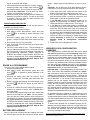
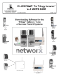
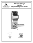
WIRE CONNECTIONS
1
2
3
4
5
6
1. Ground (Shown above for reference only)
2. Battery Connector
FIG. E: SECURE BATTERY COVER
PROGRAMMING
Your lock memory can be programmed (and re-programmed
again and again) to suit your changing requirements. Instead
of distributing metal keys, add User Codes to the lock's memory and distribute them to Users. Instead of collecting metal
keys, simply delete the User Codes from the lock memory.
To program your lock using the lock keypad, see the programming instructions (models PDL6500 & ETPDLN use
WI1835; models DL6500 & ETDLN use WI1836).
3. Motor Connector
4. Auxiliary Power / Remote Release
Wire colors in supplied plug are as follows:
Auxiliary Power:
Red: 6 - 9VDC
Black: Ground
Remote Release:
Two white wires (short to activate).
5. Ribbon Cable
6. External Relay Contacts
Wire colors are as follows:
COM-Black / NO-Yellow / NC-White
FIG. F: WIRE CONNECTIONS
TROUBLESHOOTING
Electronic Trouble:
Lock will not accept new codes during programming.
• Solution: Follow the "ERASE ALL PROGRAMMING"
procedure (see page 3), then start programming again.
Note: See the lock programming instructions for additional
programming information (models PDL6500 & ETPDLN use
WI1835; models DL6500 & ETDLN use WI1836).
Lock drains batteries quickly.
• Solution: Check for pinched or cut wires. Check for water damage. If condition persists, consult factory.
Auxiliary Power:
Red / Black wires - Use an external 7.5VDC power
source for operation without batteries.
Lock is inoperative.
• Solution: Check batteries for proper polarity and check
for pinched or cut wires.
Remote Release:
White / White wires - Wire a normally-open contact to
these two white wires. Momentarily short to unlock, thus
allowing the person to pass through door. NOTE: These
Remote Release wires are enabled from the factory. See
the lock programming instructions for additional information.
Lock sounds "pulsing beeps" (with red flickering LED) during
lock operation.
• Solution: Low battery signal - replace batteries.
Mechanical Trouble:
Lever pulls off.
• Lever Catch not fully engaged. Lock is not centered on
door. Door too thick.
Unable to assemble outside lever.
• Key and tailpiece orientation are incorrect.
Latch will not fully retract.
• Lock is not properly engaged with latch or misaligned.
Lock is not centered on door.
Key binds in lock.
• Lever Catch not fully engaged. Lock is not centered on
door. Check for proper tailpiece and proper orientation of
tailpiece.
2
WIRING AND POWER UP
External Relay Contacts:
COM-Black / NO-Yellow / NC-White - See the lock programming instructions ("Function 67") for the available relay programming options.
POWER UP
Note: Battery packs are available in two types: A "sealed"
battery pack that must be discarded if found to be weak, or
a "user-serviceable" pack that can be disassembled and
refilled with four (4) C-cell batteries (use alkaline batteries
only). For applying power for the first time, see FIRST
TIME POWER UP; if re-applying power to a lock previously
in operation, go to "WHEN POWER IS RE-APPLIED".
FIRST TIME POWER UP
1. Unpack the lock.
2. With the batteries disconnected, hold down the ;
key for 10 seconds and release.
3. Connect the batteries and listen for 3 beeps. Within 5
seconds of hearing the 3 beeps, press and hold ;
until beeping starts. This will clear the lock of all programmed data. Important: If you do NOT hear these
3 beeps, you must start over at step 2.
4. Listen for another series of beeps and LED flashes followed by 10 seconds of silence. The lock is now ready
to program. Failure to follow this exact procedure can
result in erratic lock behavior.
WHEN POWER IS RE-APPLIED
When power is re-applied to a lock that was previously in
operation, proceed as follows:
1. Disconnect battery pack connector.
2. With battery power disconnected, press and hold
down ; for 10 seconds to ensure discharge of all
capacitors.
3. Re-connect battery pack (lock will sound 3 short
beeps). If beeps are NOT heard, then restart from step
1.
4. Do not press any keys for 15 seconds.
5. After 15 seconds, the LED will flash red 6 times and 6
beeps will sound.
6. The lock is now ready for use. The pre-existing program is loaded from fixed memory. Reset the clock using Functions 38, 39 and 40 as detailed in the lock keypad programming instructions (models PDL6500 &
ETPDLN use WI1835; models DL6500 & ETDLN use
WI1836) or download the clock settings wirelessly as
described in the DL-Windows Wireless Setup & Configuration Instructions (OI352).
ERASE ALL PROGRAMMING
The "out of box" factory default will be loaded.
1. Remove the battery pack.
2. With battery power disconnected, press and hold
down ; for 10 seconds to ensure discharge of all
capacitors.
3. Re-install the battery pack (lock will sound 3 short
beeps). If beeps are not heard, then restart from step
1.
4. Within 5 seconds after hearing the 3 short beeps, press
and hold ; until the lock begins to beep, then release.
5. A series of 5 RED LED and 5 beeps will be heard followed by 10 seconds of silence, then 3 GREEN LED's
and 3 fast beeps.
All settings and programming have been erased and
the lock is now ready for use. Note: All lock programming can also be erased (without need to disconnect
the batteries) by entering Function 99 as detailed in the
lock keypad programming instructions (models PDL6500
& ETPDLN use WI1835; models DL6500 & ETDLN use
WI1836) or download the clock settings wirelessly as
described in the DL-Windows Wireless Setup & Configuration Instructions (OI352).
BATTERY REPLACEMENT
When a valid code is entered and the batteries are weak,
the LED will flicker red and the sounder will sound "pulsing
beeps". Always replace weak batteries as soon as possible.
CAUTION: Do not press any keys while batteries are disconnected or you may erase the real-time clock settings.
1. At the back of the lock, remove the two screws at the
bottom of the lock housing and remove the cover.
2. Pull out the battery pack. Disconnect the old battery
pack and quickly (within 1 minute) re-connect the new
battery pack. Listen for any beeping sounds.
3. If you DO NOT hear the 3 beeps when power is reapplied, all programming and settings have been retained, and the lock is ready for use. Go to step 5.
4. If you DO hear 3 beeps when power is re-applied, do
not press any keys for 15 seconds. After the 15 second
period, the LED will flash red 6 times and 6 beeps will
sound. Reset the clock using functions 38, 39 and 40
as detailed in the lock keypad programming instructions
(models PDL6500 & ETPDLN use WI1835; models
DL6500 & ETDLN use WI1836) or download the clock
settings wirelessly as described in the DL-Windows
Wireless Setup & Configuration Instructions
(OI352).
5. Replace the cover and tighten the screws.
WIRELESS LOCK CONFIGURATION
OVERVIEW
The Trilogy Networx™ wireless door locks allow you to upload
and download programming features wirelessly using a computer connected to a computer network. With "wireless" communication, the various cables and/or AL-DTM Data Transfer
Module devices are NOT required to transfer data. With a
few clicks of the computer mouse, you can use your computer
to retrieve logs, download User Codes and program features
into and out of each wireless door lock in your installation.
See the DL-Windows Wireless Setup & Configuration
Instructions (OI352) for complete information.
Important Note: Keypad programming of User Codes, Features, Time Zones, and Schedules is available as a temporary convenience to allow the lock to be put into use before
installing and configuring a wireless network. Therefore, all
lock programming added via the keypad cannot be retrieved
into DL-Windows. If you decide to start programming your
wireless lock via the keypad, we recommend you keep
hardcopy records (in a secure location) of all Users, their User
Codes, and any proximity cards that may have been programmed. Keeping complete and accurate records saves
time because after the wireless network is set up, any programming added via the keypad must be re-added to DLWindows and downloaded back to the lock(s).
DL-Windows software is installed on a computer that is connected to a computer network; connected to this network is
an intermediate device called a Gateway that communicates
to a radio located inside each door lock. In this way, the software allows full programming and control of each lock in the
system.
To ensure each physical lock is identified correctly by DLWindows, the factory assigns each lock a unique serial number. After locks are installed on the doors and the Gateways
are mounted, the Gateways search for new locks, allowing
them to be enrolled into the system.
Windows is a registered trademark of the Microsoft Corporation. Other products, product
names and services described in this manual are for identification purposes only and may be
trademarks of their respective companies.
3
For every new wireless lock installed on a door, we recommend that you fill out a new yellow-colored "Lock ID Card" with
the location, lock model and
serial number. These ID cards
are a convenient way to keep
track of and ensure all locks are correctly enrolled in the DLWindows Account.
Flexible Setup
In addition to wireless communication, these wireless door
locks can also be programmed at the keypad. This means
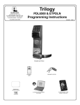
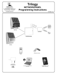
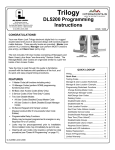
Small Network Support
Up to 63 locks for
each Gateway...
GATEWAY
#1
5)
J-4
(R
.1 1
02
ed
s8
Wir
W ire
d (R
J-45
)
or W
ireles
s
PC Running
DL-Windows
Software
W
or
Large Network Support
Lock
#1...
Rad
Rad
io ) )
)))
GATEWAY
#1
5)
J-4
(R
.1 1
02
ed
s8
W ir
Lock
#63
W ire
d (R
J-45
)
or W
ireles
s
E X P A N D A B L E
...Up to 32 Gateways
for each system
W ir
or
W
PC Running
DL-Windows
Software
ed
(R
J-4
5)
ire
les
s
80
2.1
1
Lock
#1...
Up to 63 locks for
each Gateway...
)))
io ) )
les
ire
Router
that locks can be installed on the doors and immediately be
put into use via keypad programming--even before a wireless
network is set up. Therefore, you can install the locks on the
doors before configuring the wireless network, or you can set
up the wireless network first and add locks later. If you wish,
you can even start by designing a "virtual" system within DLWindows (creating new Accounts, adding Users and configuring lock features, etc.), then set up the network and install the
lock hardware later. But in the end, after your lock hardware
is physically installed and the network is up and running, you
can run DL-Windows to link the "virtual" system saved on
your computer with the "real" lock hardware on the doors.
W
or
Existing
Corporate
Ethernet
Network
io ) )
Rad
Rad
io
)))
)))
les
ire
))
Lock
#63
E X P A N D A B L E
...Up to 32 Gateways
for each system
Wir
ed
(R
J-4
ire
5)
les
s
or
W
GATEWAY
#32
80
2.1
1
Rad
io
)))
)
...Lock
#2000
GATEWAY
#32
Rad
io ) )
))
...Lock
#2000
ALARM LOCK LIMITED WARRANTY
ALARM LOCK SYSTEMS, INC. (ALARM LOCK) warrants its products to be
free from manufacturing defects in materials and workmanship for 24 months
following the date of manufacture. ALARM LOCK will, within said period, at its
option, repair or replace any product failing to operate correctly without charge
to the original purchaser or user.
This warranty shall not apply to any equipment, or any part thereof, which
has been repaired by others, improperly installed, improperly used, abused,
altered, damaged, subjected to acts of God, or on which any serial numbers
have been altered, defaced or removed. Seller will not be responsible for any
dismantling or reinstallation charges.
THERE ARE NO WARRANTIES, EXPRESS OR IMPLIED, WHICH
EXTEND BEYOND THE DESCRIPTION ON THE FACE HEREOF. THERE IS
NO EXPRESS OR IMPLIED WARRANTY OF MERCHANTABILITY OR A
WARRANTY OF FITNESS FOR A PARTICULAR PURPOSE. ADDITIONALLY,
THIS WARRANTY IS IN LIEU OF ALL OTHER OBLIGATIONS OR
LIABILITIES ON THE PART OF ALARM LOCK.
Any action for breach of warranty, including but not limited to any implied
warranty of merchantability, must be brought within the six months following
the end of the warranty period. IN NO CASE SHALL ALARM LOCK BE LIABLE
TO ANYONE FOR ANY CONSEQUENTIAL OR INCIDENTAL DAMAGES
FOR BREACH OF THIS OR ANY OTHER WARRANTY, EXPRESS OR
IMPLIED, EVEN IF THE LOSS OR DAMAGE IS CAUSED BY THE SELLER'S
OWN NEGLIGENCE OR FAULT.
In case of defect, contact the security professional who installed and
maintains your security system. In order to exercise the warranty, the product
must be returned by the security professional, shipping costs prepaid and
insured to ALARM LOCK. After repair or replacement, ALARM LOCK assumes
the cost of returning products under warranty. ALARM LOCK shall have no
obligation under this warranty, or otherwise, if the product has been repaired by
others, improperly installed, improperly used, abused, altered, damaged,
subjected to accident, nuisance, flood, fire or acts of God, or on which any
serial numbers have been altered, defaced or removed. ALARM LOCK will not
be responsible for any dismantling, reassembly or reinstallation charges.
This warranty contains the entire warranty. It is the sole warranty and any
prior agreements or representations, whether oral or written, are either merged
herein or are expressly canceled. ALARM LOCK neither assumes, nor
authorizes any other person purporting to act on its behalf to modify, to
4
change, or to assume for it, any other warranty or liability concerning its
products.
In no event shall ALARM LOCK be liable for an amount in excess of ALARM
LOCK's original selling price of the product, for any loss or damage, whether
direct, indirect, incidental, consequential, or otherwise arising out of any failure
of the product. Seller's warranty, as hereinabove set forth, shall not be
enlarged, diminished or affected by and no obligation or liability shall arise or
grow out of Seller's rendering of technical advice or service in connection with
Buyer's order of the goods furnished hereunder.
ALARM LOCK RECOMMENDS THAT THE ENTIRE SYSTEM BE
COMPLETELY TESTED WEEKLY.
Warning: Despite frequent testing, and due to, but not limited to, any or all of
the following; criminal tampering, electrical or communications disruption, it is
possible for the system to fail to perform as expected. ALARM LOCK does not
represent that the product/system may not be compromised or circumvented;
or that the product or system will prevent any personal injury or property loss
by burglary, robbery, fire or otherwise; nor that the product or system will in all
cases provide adequate warning or protection. A properly installed and
maintained alarm may only reduce risk of burglary, robbery, fire or otherwise
but it is not insurance or a guarantee that these events will not occur.
CONSEQUENTLY, SELLER SHALL HAVE NO LIABILITY FOR ANY
PERSONAL INJURY, PROPERTY DAMAGE, OR OTHER LOSS BASED ON
A CLAIM THE PRODUCT FAILED TO GIVE WARNING. Therefore, the
installer should in turn advise the consumer to take any and all precautions for
his or her safety including, but not limited to, fleeing the premises and allege
police or fire department, in order to mitigate the possibilities of harm and/or
damage.
ALARM LOCK is not an insurer of either the property or safety of the user's
family or employees, and limits its liability for any loss or damage including
incidental or consequential damages to ALARM LOCK's original selling price of
the product regardless of the cause of such loss or damage.
Some states do not allow limitations on how long an implied warranty lasts
or do not allow the exclusion or limitation of incidental or consequential
damages, or differentiate in their treatment of limitations of liability for ordinary
or gross negligence, so the above limitations or exclusions may not apply to
you. This Warranty gives you specific legal rights and you may also have other
rights which vary from state to state.