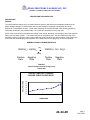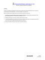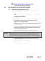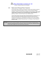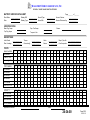
1
Operating and Maintenance Manual For Nickel-Cadmium Aircraft Batteries MarathonNorco Aerospace, Inc. P.O. Box 8233 Waco TX. 76714-8233 Phone: (254) 776-0650 8301 Imperial Drive Waco, TX. 76712-6588 Fax: (254) 776-6558 E-Mail: [email protected] Website: www.mnaerospace.com 24-34-00 JUN 23/97 Rev 12 JUL 11/14 MARATHONNORCO AEROSPACE, INC. NICKEL-CADMIUM AIRCRAFT BATTERIES RECORD OF REVISIONS Original Issue Date: JUN 23/97 Rev No. 1 2 3 4 5 6 7 8 9 10 11 12 Issue Date 10/23/97 06/30/99 09/04/01 03/28/03 11/30/03 11/19/04 04/15/06 05/10/11 06/03/11 07/25/11 11/09/12 07/11/14 Date Inserted By Rev No. Issue Date Date Inserted By Rev No. 24-34-00 Issue Date Dated Inserted By RR-1 JUL 11/14 MARATHONNORCO AEROSPACE, INC. NICKEL-CADMIUM AIRCRAFT BATTERIES RECORD OF TEMPORARY REVISIONS Temporary Rev. No. Page Number Issue Date By Date Removed 24-34-00 By RTR-1 APR 15/06 MARATHONNORCO AEROSPACE, INC. NICKEL-CADMIUM AIRCRAFT BATTERIES SERVICE BULLETIN LIST Number Revision 24-34-00 Date SBL-1 APR 15/06 MARATHONNORCO AEROSPACE, INC. NICKEL-CADMIUM AIRCRAFT BATTERIES LIST OF EFFECTIVE PAGES SUBJECT PAGE Title DATE SUBJECT Capacity Test PAGE Page 701 DATE JUL 11/14 Capacity Test Page 702 JUL 11/14 Reconditioning Page 801 MAY 10/11 Cleaning Page 901 Page 902 APR 15/06 APR 15/06 JUL 11/14 Record of Revisions RR-1 JUL 11/14 Record of Temp Revisions RTR-1 APR 15/06 Service Bulletin List SBL-1 APR 15/06 List of Effective Pages LEP-1 JUL 11/14 Replacement of Cells And Battery Repair Page 1001 Page 1002 MAY 10/11 MAY 10/11 Table of Contents TC-1 TC-2 APR 15/06 APR 15/06 Battery Disassembly & Reassembly Page 1101 Page 1102 MAY 10/11 APR 15/06 Introduction Definitions of Battery Terms INTRO-1 INTRO-2 INTRO-3 INTRO-4 INTRO-5 MAY 10/11 APR 15/06 APR 15/06 JUN03/11 JUL 11/14 Battery Maintenance Flow Chart Page 1201 Page 1202 JUN 03/11 MAY 10/11 Trouble Shooting Page 1 Page 2 Page 3 APR 15/06 APR 15/06 APR 15/06 Page 1301 Page 1302 Page 1303 MAY 10/11 APR 15/06 APR 15/06 Storage Page 1401 May 10/11 Page 4 APR 15/06 Shipping Page 1501 MAY 10/11 Page 101 Page 102 Page 103 Page 104 Page 105 APR 15/06 MAY 10/11 MAY 10/11 MAY 10/11 APR 15/06 Warranty Information Page 1601 JUL 25/11 Special Tools Page 1701 NOV 9/12 Recording Keeping Page 1801 Page 1802 JUL 25/11 JUL 25/11 Electrical Leakage Page 201 APR 15/06 Torque Requirements Page 301 JUL 11/14 Sensor Assembly Inspection Page 401 Page 402 Page 403 Page 404 Page 405 Page 406 Page 407 Page 408 APR 15/06 MAY 10/11 MAY 10/11 MAY 10/11 JUL 11/14 JUL 11/14 JUL 11/14 JUL 11/14 Charge Page 501 Page 502 Page 503 APR 15/06 APR 15/06 JUL 11/14 Electrolyte Level Adjustment Page 601 Page 602 Page 603 Page 604 Page 605 JUL 11/14 APR 15/06 JUL 11/14 APR 15/06 APR 15/06 Description and Operation Inspection 24-34-00 LEP-1 JUL 11/14 MARATHONNORCO AEROSPACE, INC. NICKEL-CADMIUM AIRCRAFT BATTERIES TABLE OF CONTENTS SUBJECT Introduction PAGE INTRO-1 Description and Operation 1 Inspection 101 Electrical Leakage 201 Torque Requirements 301 Sensor Assembly Inspection 401 Charge 501 Electrolyte Level Adjustment 601 Capacity Test 701 Reconditioning 801 Cleaning 901 Replacement of Cells and Battery Repair 1001 Battery Disassembly and Reassembly 1101 Battery Maintenance Flow Chart 1201 Trouble-Shooting 1301 Storage 1401 Shipping 1501 Warranty Information 1601 Special Tools 1701 Record Keeping 1801 24-34-00 TC-1 APR 15/06 MARATHONNORCO AEROSPACE, INC. NICKEL-CADMIUM AIRCRAFT BATTERIES LIST OF FIGURES, ILLUSTRATIONS AND TABLES PAGE # Constant Current Charge Curve Figure 1 1 Typical Constant Current Discharge Curves Figure 2 3 Inspection Gauge Figure 3 102 Recommended Voltage Regulator Settings Table 1 103 Temperature Charge Voltage Relationship Figure 4 105 Torque Requirements Table 2 301 Temperature Sensor Specifications Table 3 402 Reflex and Constant Current Charge Rates Table 4 503 Syringe and Nozzle Assembly Figure 5 601 Syringe and Nozzle Assembly Application Table 5 601 Maximum Allowable Water Consumption Table 6 603 Proper Electrolyte Level Adjustment Figure 6 604 Water Loss at Various Rates of Overcharge Figure 7 605 Theoretical Water Loss and Volume of Gas Resulting from Overcharge Figure 8 605 Capacity test Rates Table 7 702 24-34-00 TC-2 APR 15/06 MARATHONNORCO AEROSPACE, INC. NICKEL-CADMIUM AIRCRAFT BATTERIES INTRODUCTION This manual contains shop verified instructions for proper installation, operation and maintenance of MarathonNorco’s Nickel-Cadmium batteries. These instructions are grouped in topics shown in the Table of Contents. They are for the operation, testing, and repair of MarathonNorco’s battery products. This manual is designed to service the batteries based on the cell type within the battery. Batteries covered by this manual are listed within the INTRO section. This listing identifies the applicable cell type used within the battery to establish the servicing criteria listed in the various tables and charts within this manual. WARNING: SERIOUS INJURY CAN RESULT FROM CARELESSNESS WHILE HANDLING AND WORKING WITH NICKEL-CADMIUM BATTERIES. PLEASE OBSERVE THE FOLLOWING SAFETY RULES WHILE WORKING WITH THESE BATTERIES. 1. Remove all metal articles such as bracelets and rings. 2. Metal tools must be insulated. 3. Wear protective clothing and eye protection. The electrolyte can cause burns if in contact with skin or eyes. 4. Do not smoke or hold naked flames near batteries on charge. These batteries give off a mixture of oxygen and hydrogen during charge, which, if allowed to accumulate in a confined space, could cause an explosion. Do not charge the battery on the bench with the cover on. 5. Do not mix lead-acid and nickel-cadmium battery servicing in the same shop area. 6. Do not use petroleum spirits, trichloroethylene or other solvents. READ AND UNDERSTAND THE CAUTIONS AND WARNINGS STATED THROUGHOUT THIS MANUAL BEFORE PROCEEDING WITH SERVICING PROCEDURES. CARELESSNESS MAY RESULT IN THE RAPID AND UNCONTROLLED RELEASE OF ELECTRICAL, CHEMICAL OR HEAT ENERGY. 24-34-00 INTRO-1 MAY 10/11 MARATHONNORCO AEROSPACE, INC. NICKEL-CADMIUM AIRCRAFT BATTERIES DEFINITIONS OF COMMONLY USED BATTERY TERMS Ampere Hours A unit of electrical measurement used to describe the capacity of a cell or battery. The product of discharge current (in amperes) X the time of discharge (in hours). It is also used to describe the amount of electrical energy put back into a battery during the charging process. Abbreviated as Ah or Amp. hrs. This rating system helps to compare the performance of different sizes of cells and batteries. State of Charge The amount of stored energy (capacity) available in a rechargeable battery. Usually expressed as a percentage of its full capacity. Capacity A measure of the stored electrical energy that is available from a charged battery. Generally expressed in Ampere Hours, or as a % of the nominal (nameplate) capacity Electrolyte The conductive medium that provides for the movement of ions (current flow) between the positive and negative plates of a cell; an alkaline solution of Potassium Hydroxide in nickel-cadmium aircraft cells. Constant Current Charging A method used to charge a battery in which a predetermined, fixed current is passed through it. End-of-Charge Voltage The voltage of a battery at the conclusion of a charge measured while the battery is still on charge. Constant Potential Charging (Constant Voltage) This refers to a method in which a fixed voltage source is applied across the battery terminals. The charge current is variable and depends primarily upon the difference in voltage between the voltage source and that of the battery. The initial charge current is high and decreases as the battery accepts the charge and its voltage increases. Fading The loss of capacity that occurs when a battery is cycled with minimal overcharge. A correctable condition through re-conditioning Separator A material that is used to prevent the metallic contact between the positive and negative plates. Trickle Charge A continuous constant current, low-rate charge (slightly more than the self-discharge rate) suitable to maintain a battery in a fully charged condition. Gas Barrier A membrane in the separator system that prohibits the recombination of oxygen (produced at the positive plate) on negative plate. Rated or Nominal Capacity The nominal nameplate capacity rating of a nickelcadmium battery generally refers to the number of Ampere-hours that the battery can deliver when discharged at the 1-hour rate to 1.0 volt per cell. Nominal Voltage (Name Plate) The voltage of a fully charged cell or battery while delivering current. The nominal voltage of a nickelcadmium battery cell is 1.2 volts, therefore a 20-cell battery would have a nominal voltage of 24 volts, and a 19 cell is 22.8 volts. (Note: Older batteries use a different convention for nominal voltage). "C" Rate That discharge rate, in nominal or nameplate amperes, at which a battery or cell will yield its capacity to a 1.0 volt per cell endpoint in one hour. Fractions or multiples of the C rate are also used. C/5 refers to the rate at which a battery will discharge its capacity in 5 hours. 2C is twice the C rate or that rate at which a battery will discharge its capacity in about 1/2 hour. Example: a 25 amperehour battery will have a C rate of 25 amperes, a C/5 rate of 5 amperes and a 2C rate of 50 amperes. Open Circuit Voltage The voltage of a battery at rest, that is, with no charge or discharge current flowing 24-34-00 INTRO-2 APR 15/06 MARATHONNORCO AEROSPACE, INC. NICKEL-CADMIUM AIRCRAFT BATTERIES Deep Discharge (Cycle) A discharge in which most or all of the available capacity is withdrawn from a battery and the cells are brought individually to a zero volt condition. Reconditioning A procedure consisting of a deep discharge and a constant current charge that is used to correct cell imbalance that may occur during continual cyclic use of a rechargeable battery. Shorting Clip A short length of wire (with or without a low value resistor) or a metal spring, used to "short" a cell to zero volts. 24-34-00 INTRO-3 APR 15/06 MARATHONNORCO AEROSPACE, INC. NICKEL-CADMIUM AIRCRAFT BATTERIES MarathonNorco Aircraft Batteries Battery Type Cell Type Battery Type Cell Type Battery Type Cell Type Battery Type Cell Type 10-20H120 20H120 BB415/U 10H120 CA-154-1 15M220 CA-727-20CR 24M220CR 10-5H120 5H120 BB432/A 12M220 CA-154-2 15M220 CA-727-7 24M220CR 10-81H120 81H120 BB432A/A 12H120 CA-154-2A 15M220 CA-727-9 24H100 18-6H120 6H120 BB432B/A 12H120C CA-154-3A 15M220 CA-737 24M220 19-10H120 10H120 BB433/A 36H120 CA-154-4 15M220 CA-9 24H120 19-24H120 24H120 BB433A/A 36H120 CA-154-5 15M220 CA-91-20 24H120 20-14M220 14M220 BB434/A 24H120C CA-154-7 15M220 CA-9-20 24H120 20-18H120 18H120 BB476/A 10HE120 CA-16N 36H120 CA-9-20A 24H120 20-5H120 5H120 BB600A/A 36H120 CA-1700 17H100 CTCA-21H-1 20H120 23-3H120 3H120 BB641/A 10H120 CA-170A 17H100 CTSP-280 28SP100 5-81H120 81H120 BB649A/A 20H120 CA-174 17H100 CTSP-280-1 28SP100 81757/1-2 12H120 BB664/A 10HE120C CA-176 17H100 CTSP-400 40SP100 81757/10-1 6H120 BB672/U 3H120 CA-20H 20H120 DTSP-280L 28SP100 81757/11-1 24H120 BB676/A 10H120 CA-20H-20 20H120 DTSP-400L 40SP100 81757/11-2 24H120 BB678A/A 10H120 CA-21H-1 20H120 20SPE100 81757/11-3 24H120 BB693/U 36H120C CA-21H-20 20H120 Goalkeeper, 142D5750 GP-180 81757/11-4 24H120 BB708/A 5H120 CA-24A 24M220CR GSP-400 44SP100 81757/7-3 12H120 BB716/A 5H120 CA-27 24ME220(C) GTMA-5-20 36H120 81757/8-2 24H120 BTCA-5-20 36H120 CA-27-20 24ME220(C) GTSP-400 44SP100 81757/8-3 24H120 BTCA-9-20 24H120 CA-27-20C 24ME220C KCA-727 24M220 81757/8-4 24H120 BTCA-9-20A 24H120 CA-31 3H120 KCA-727-20 24M220 81757/8-5 24H120 BTCA-400 40H100 CA-376 36H120 KCA-727-20C 24M220C 81757/9-2; 36H120 BTMA-5 36H120 CA-4 24M220CR KCA-727-20CR 24M220C 81757/9-3 36H120 BTMA-5-20 36H120 CA-400 40H100 KSP-400 40SP100 ATCA-21H 20H120 BTSP-179 17SP100 CA-400A 40H100 KSP-400L 40SP100 ATCA-21H-1 20H120 BTSP-400 40SP100 CA-4-20 24M220CR KTCA-21H-20 20H120 ATCA-21H-2 20H120 BTSP-4445L 44SP100 CA-5 36H120 MA-11 24M220CR ATCA-21H-2H 20H120 CA-101(N) 10H120 CA-51(N) 5H120 MA-2 65H132 ATCA-441 40H100 CA-103 10H120 CA-53(N) 5H120 MA-300H 3H120 ATSP-280 28SP100 CA-106 10H120 CA-54 5H120 MA-5 36H120 ATSP-400 40SP100 CA-10N 10H120 CA-54-1 5H120 MA-500(H) 5H120 ATSP-400-2 40SP100 CA-121 12M220 CA-54-2 5H120 MA510 5H120 ATSP-44 44SP100 CA-125 3H120 CA-54-3 5H120 MA-5-20 36H120 ATSP-441 40SP100 38SP100 CA-125-20 3H120 CA-54-3C 5H120 MA-5-C 36H120 ATSP-900L-1 24SP100 CA-126 3H120 CA-5H 36H120 MA-7 12M220 BA02-04 5H120 CA-13 36H120 CA-7 12M220 MA-9 24H120 BA02-05 5H120 CA-138 38H100 CA-727-20 24M220CR PTMA-5-20 36H120 BB400 3H120 CA-139 38H100 CA-727-20C 24M220C PTSP-400 40SP100 24-34-00 INTRO-4 JUN 03/11 MARATHONNORCO AEROSPACE, INC. NICKEL-CADMIUM AIRCRAFT BATTERIES MarathonNorco Aircraft Batteries Battery Type Cell Type Battery Type Cell Type Battery Type Cell Type PTSP-400-1 40SP100 TCA-109L-1 10H120C TSP-1760-L-1 17SP100 SP-138 38SP100 TCA-1069L 10H120C TSP-25 25SP100 SP-170A 17SP100 TCA-1735 17H100 TSP-280 28SP100 SP-170AL 17SP100 TCA-1742 17H100 TSP-281 28SP100 SP-1700 17SP100 TCA-1752 17H100 TSP-283 28SP100 SP-1700L 17SP100 TCA-1753 17H100 TSP-400WB 40SP100 SP-176 17SP100 TCA-1754 17H100 TSP-400X 40SP100 SP-178 17SP100 TCA-183CH 18H120 TSP-40204B 40SP100 SP-276 24SP100 TCA-1892L 18H120 TSP-408L-1 40SP100L SP-280 28SP100 TCA-21H-1 20H120 TSP-409L-1 40SP100L SP-376 44SP100 TCA-21H-2 20H120 TSP-410 40SP100 SP400 40SP100 TCA-21H-20 20H120 TSP-414 44SP100 SP400L 40SP100 TCA-2492L 24M220CR TSP-420L 40SP100 SP-401 38SP100 TCA-440 40H100 TSP434 44SP100 SP-444L 44SP100 TCA-5 36H120 TSP-440 40SP100 SP-747 38SP100 TCA-52 52H120C TSP-4412 44SP100 SP900 24SP100 TCA-5-20 36H120 TSP-442 44SP100 SP-900A 24SP100 TCA-5-20-1(C) 36H120 TSP-44204B 44SP100 SP-910 24SP100 TCA-7 12M220 TSP-4460 44SP100 STCA-16L 36H120 TMA-4 24M220CR TSP-4492L 44SP100 STCA-162-2 36H120 TMA-5-20 36H120 TSP-455-1 40SP100 STCA-400 40H100 TMA-5-20(c) 36H120 TSP-46-1 46SPE100 STCA-400A 40H100 TPSP-941 24SP100 TSP-900A 24SP100 STCA-420-2 40H100 TPSTSP-941 24SP100 TSP-9117A 24SP100 STCA-930A 24H100 TSP-15 15SP100 TSP-9117B 24SP100 STMA-2 65H132 TSP-1708L 17SP100 TSP-940 24SP100 STMA-5-20 36H120 TSP-1722 17SP100 TTMA-5-20C 36H120 STMA-9 24H120 TSP-1728 17SP100 UTSP-400 40SP100 STSP-400 40SP100 TSP-1735 17SP100 UTSP-440 40SP100 STSP-403 40SP100 TSP-1735L 17SP100 UTSP-460L 44SP100 STSP-444 44SP100 TSP-1742 17SP100 UTSP-460L-1 44SP100 STSP444L 44SP100 TSP-1749L 17SP100 STSP-901 24SP100 TSP-1753 17SP100 STSP-930 24SP100 TSP-1754 17SP100 TCA-103C 10H120C TSP-1755 17SP100 TCA-106 10H120 TSP-1757 17SP100 TCA-106-3 10H120 TSP-1760L 17SP100 24-34-00 INTRO-5 JUL 11/14 MARATHONNORCO AEROSPACE, INC. NICKEL-CADMIUM AIRCRAFT BATTERIES DESCRIPTION AND OPERATION DESCRIPTION General The nickel-cadmium battery cell is an electrochemical system in which the active materials contained in the plates undergo changes in oxidation state with very little change in electrolyte concentration due to the production or consumption of water. These active materials are virtually insoluble in the alkaline (potassium hydroxide) electrolyte in any oxidation state. As a result the electrodes are very long-lived. Some of the electrochemical mechanisms involved in the charge, discharge, and storage of the nickel-cadmium battery cell are rather complex. This is especially true of the positive plate. A brief simplified account of the essential reactions is offered in order to help initiate the reader into the theory and principles of this system and thus further the understanding of the operation of the battery and the role played by its main components. GENERAL NICKEL-CADMIUM EQUATION, chg. → 2Ni(OH)2 + Cd(OH)2 2NiOOH + Cd + 2H2O ← dischg. Positive Plate Negative Plate Positive Plate Negative Plate FIGURE 1 Typical Constant Current Charge Curve 5-Hour Rate CELL VOLTAGE TYPICAL CONSTANT CURRENT CHARGE CURVE 5-HOUR RATE 1.8 1.7 1.6 1.5 1.4 1.3 1.2 0 1 2 3 4 5 6 7 TIME/HOURS 24-34-00 Page 1 APR 15/06 MARATHONNORCO AEROSPACE, INC. NICKEL-CADMIUM AIRCRAFT BATTERIES Charge Charging results in the conversion of electrical energy to stored chemical energy. The active materials, in a discharged condition, are cadmium hydroxide in the negative plates and nickel hydroxide in the positive plates. With the application of a charging current, these active materials undergo a chemical change. The negative material (Cadmium Hydroxide) gradually gains electrons and is converted to metallic cadmium (Cd); the positive material is gradually brought to a higher state of oxidation (loses electrons). As long as the charging current continues to flow through the battery, these changes will take place until the active materials in both electrodes are completely converted, at which point, overcharge commences. Toward the end of the process (as the materials approach a full charge condition), and during overcharge, gas will be evolved and released through the cell vent. This gas results from the electrolysis of the water component of the electrolyte. The gas evolved at the negative plates is hydrogen and at the positive plates is oxygen. The amount of gas evolved depends upon the charge rate during the period in which the cells are being overcharged. After complete conversion of the active materials has occurred, the further 2 application of charge current will only cause further electrolysis of the water and I R heating. Discharge Discharging results in the conversion of the chemical energy stored in the cell to electrical energy. During discharge, the chemical reactions which occurred in charging are reversed. The active material (Cd) in the negative plates gradually loses electrons and changes to cadmium hydroxide. The active material in the positive plates gains electrons and changes to nickel hydroxide. No gassing occurs during a normal discharge. The insolubility of the active materials and the fact that the potassium hydroxide does not participate in the cell reaction results in the very flat Ni-Cd discharge voltage curve. The rate at which the conversions take place is primarily determined by the external resistance (load) introduced into the circuit in which the cell is connected. Due to its construction, the MarathonNorco cell has an extremely low internal resistance, and its ability to deliver high currents is due to this factor. 24-34-00 Page 2 APR 15/06 MARATHONNORCO AEROSPACE, INC. NICKEL-CADMIUM AIRCRAFT BATTERIES Charge, Discharge and overcharge equations: Positive plate Charge Discharge → ← 2Ni(OH)2 + 2(OH)(Nickel Hydroxide) Overcharge 4(OH)→ → ← 2Ni OOH + 2H2O + 2e(Nickel Oxy Hydroxide) O2 + 2H2O + 4e- Negative Plate Charge Discharge → ← Cd(OH)2 + 2e- → - (Cadmium Hydroxide) Cd° + 2(OH) (Cadmium) Overcharge 4H2O + 4e- 2H2 + 4(OH) → Overcharge (Net Cell Reaction) 4e2H2O → 2H2 + O2 Constant Current Discharge For Typical 20 Cell Battery: Rate a parameter Figure 2 TYPICAL CONSTANT CURRENT DISCHARGE CURVES 24-34-00 Page 3 APR 15/06 MARATHONNORCO AEROSPACE, INC. NICKEL-CADMIUM AIRCRAFT BATTERIES Capacity Capacity is measured quantitatively in ampere-hours delivered at a specified discharge rate to a specified cut-off voltage at room temperature. The cut-off voltage is 1.0 volt per cell. Battery available capacity depends upon several factors including such items as: 1. Cell design (cell geometry, plate thickness, hardware, and terminal design govern performance under specific usage conditions of temperature, discharge rate, etc.). 2. Discharge rate (high current rates yield less capacity than low rates). 3. Temperature (capacity and voltage levels decrease as battery temperature moves away from the 60°F (16°C) to 90°F (32°C) range toward the high and low extremes). 4. Charge rate (higher charge rates generally yield greater capacity). 24-34-00 Page 4 APR 15/06 MARATHONNORCO AEROSPACE, INC. NICKEL-CADMIUM AIRCRAFT BATTERIES 1.0 INSPECTION 1.1 Delivery Inspection When the battery is unpacked, a thorough inspection should be made to ensure that no damage occurred during shipment. Inspect the shipping container as well as the battery. Before putting the battery into service, check the following points carefully. 1.1.1 Damage See if any liquid has spilled into the shipping container. This may be a sign of a damaged cell. Check for dented battery container. Check for cracked cell cases or covers. Do not place a damaged battery into service. Report any signs of improper handling to the shipping company. 1.1.2 Shorting straps Some batteries are shipped with shorting devices across the main power receptacle output terminals. Before subjecting battery to electrical service this device must be removed 1.1.3 Electrical connections Test all terminal hardware to ensure tightness. If necessary re-torque them to the proper value. Poor electrical contact between mating surfaces may reduce discharge voltage, cause local overheating and damage the battery. 1.14 Liquid level - Do not add water to a battery except near the end of a constant current charge. Some exceptions may be noted later. Addition of water, except at the proper time during the charge will cause spewing of electrolyte to take place during the subsequent charge. MarathonNorco batteries are shipped with the proper amounts of electrolyte. When a battery has been discharged or allowed to stand for a long period of time, the electrolyte becomes absorbed into the plates. Since the battery has been shipped in a discharged condition, the liquid level of the cells may appear to be low. Charging the battery will cause the liquid level of the individual cells to rise to the proper operating level. If this does not happen, add sufficient distilled or demineralized water (using the proper syringe and nozzle) to the cells during the last 15 minutes of the topping charge, until the correct liquid level is reached. BEFORE CHARGING THE BATTERY READ AND BECOME FAMILIAR WITH THE CHARGE PROCEDURE. 24-34-00 Page 101 APR 15/06 MARATHONNORCO AEROSPACE, INC. NICKEL-CADMIUM AIRCRAFT BATTERIES WARNING: 1.2 THE ELECTOLYTE USED IN NICKEL-CADMIUM BATTERIES IS A STRONG CAUSTIC SOLUTION OF POTASSIUM HYDROXIDE. USE RUBBER GLOVES, AN APRON AND A FACE SHIELD WHEN REPAIRING OR SERVICING THE BATTERY. IF ELECTROLYTE IS SPILLED OR SPRAYED ON CLOTHING OR OTHER MATERIALS, IT SHOULD BE BATHED IMMEDIATELY WITH LARGE QUANTITIES OF WATER NEUTRALIZED WITH A WEAK ACID SOLUTION SUCH AS VINEGAR. IF ELECTROLYTE GETS INTO THE EYES, FLUSH COPIOUSLY WITH WATER AND GET MEDICAL ATTENTION IMMEDIATELY. INSPECTION IN THE AIRCRAFT 1.2.1 Vent Lines When installing a battery in the aircraft, check the vent lines for obstructions, leaks or damage of any kind and repair or replace. Check battery box vents for obstructions or cracks and repair. 1.2.1 Battery Disconnect The following procedure defines an inspection program to field check the aircraft battery quick disconnect. 1.2.2 Equipment Required Quick disconnect inspection gauge INSPECTION GAUGE FIGURE 3 1.2.3 Procedure Inspection of Battery Quick Disconnect: Remove all electrical loads from the battery then disengage the battery disconnect from the mating receptacle, and inspect for the following: A. Evidence of corrosion or pitting of the power contacts. B. Excessive free-play in the hand wheel- worn assembly, broken pins. 24-34-00 Page 102 MAY 10/11 MARATHONNORCO AEROSPACE, INC. NICKEL-CADMIUM AIRCRAFT BATTERIES C. Evidence of arcing of burn marks on the power contacts. This is caused when the disconnect is removed under electrical load. D. Insert the .385 inch diameter end of the inspection gauge into each power contact to a depth of .437 inches. The fit shall be snug with a force to remove greater than one (1) pound. This is to test the resiliency of the power contact to an oversized pin. E. Insert the .370 inch diameter end of the inspection gauge into each power contact to a depth of .437 inches. The fit shall also be snug with a nominal force to remove one (1) pound. This will ensure proper contact to a worn or undersized contact pin. F. Replace if required. 1.2.4 Voltage Regulator The voltage regulator should be set at a level consistent with the normal ambient temperature band and should be set on the aircraft after a start and a few minutes into the charging period (seeTable 1). Periodic checks to correct out- of-tolerance regulators and replacement of defective units will reduce the possibility of inadvertent increases in charging voltage with the resultant rise in charge current and battery temperature and water consumption. Recommended voltage settings measured at the battery terminals and applicable to room temperature conditions, under a known time span of 4 hours are shown in Table 1. (These are nominal values computed by multiplying the number of cells in the battery by a factor of approximately 1.5). For voltage regulation at ambient temperature higher or lower than 75°F (24° C), see Figure 3. Table 1 - Recommended Voltage Regulator Setting at 75°F (24°C) Number of Cells Nominal Battery Voltage Time In Hours Voltage Maximum* Voltage Regulator Setting 5 10 12 19 20 22 6 12 15 22.8 24 26.0 2-4 2-4 2-4 2-4 2-4 2-4 7.5-7.75 15.0-15.5 18.0-18.5 28.0-29.0 28.5-30.0 31.0-33.5 7.50 15.00 18.00 28.50 30.00 33.00 * Constant potential charging voltage and time apply to all ampere-hour ratings, subject only to number of cells per battery 24-34-00 Page 103 MAY 10/11 MARATHONNORCO AEROSPACE, INC. NICKEL-CADMIUM AIRCRAFT BATTERIES Figure 4 Temperature vs. Charge Voltage Relationship MAXIMUM RECOMMENDED CONSTANT POTENTIAL CELL CHARGE VOLTAGE AT VARIOUS TEMPERATURES Charge Voltage, V/cell Temperature vs Charge Voltage MAXIMUM RECOMMENDED CONSTANT POTENTIAL CHARGE VOLTAGE AT VARIOUS TEMPERATURES 1.75 1.65 1.55 1.45 1.35 -40 -20 0 20 40 60 80 100 120 Battery Temperature, F° 24-34-00 Page 104 MAY 10/11 MARATHONNORCO AEROSPACE, INC. NICKEL-CADMIUM AIRCRAFT BATTERIES 1.3 Inspection - Received in for Service When a battery is received in the shop for routine servicing, the following inspections should be performed: Visually inspect can and cover for dents, damage, epoxy coating separation, vent tube obstruction, latch function and cover seal condition. Any evidence of discrepancies, in above shall be cause for replacement of the parts. Remove the battery cover and inspect for the following: Clean top of cells and connectors with a nylon brush. Blow out residue with oil-free compressed air using standard safety precautions. If cells are exceptionally dirty, connecting links, hardware, and cells may need to be removed, washed in warm water and dried. If this is required, discharge the battery before disassembly. Verify that the polarity of the cells and position of the internal connections are correct. Inspect intercell connectors for corrosion, burns or discoloration. Clean with an eraser or replace as required. Remove vent plugs and inspect “O” rings and vent sleeves for damage or hardening. Replace if defective. If necessary, wash vent plugs in warm water to remove the white powder (potassium carbonate) from vent holes. Dry with oil-free compressed air using standard safety precautions. 1.3.1 Inspection of Battery Power Connector Inspect for corrosion or pitting on the contact pins. Inspect for arcing or burn marks on the contact pins. This is caused when the disconnect is removed under electrical load. Inspect for battery electrolyte leakage through the receptacle body and/or the contact pins. NOTE: Electrolyte leakage can be noticed by a discoloration of the receptacle body with the glass fibers exposed. Gauge each contact pin diameter using dial calipers that are capable of reading to .001 inch. The diameter shall be .375 ± .005 inches. 1.3.2 Inspection of Sensor Receptacle (if so equipped) Examine sensor connector for pin or locking mechanism damage. CAUTION: The electrolyte used in the battery is a caustic solution of Potassium Hydroxide. Avoid contact with any part of the body. 24-34-00 Page 105 APR 15/06 MARATHONNORCO AEROSPACE, INC. NICKEL-CADMIUM AIRCRAFT BATTERIES 2.0 ELECTRICAL LEAKAGE To determine if external leakage is of such a magnitude as to require a complete battery cleaning set the range selector of a multimeter to the 500 milliampere range or higher. Place the positive lead of the meter on the positive terminal of the battery receptacle and touch the negative lead of the meter to any exposed metal on the battery can. NOTE: Many MarathonNorco batteries are supplied with epoxy coated battery cans and covers. Where epoxy coated cans are used, current flow may be measured between the battery terminals and the screws that are used to mount the main connector. If the measurement is within the meter limits, connect the negative lead of the meter to the battery can. Record this current value. Repeat the above, connecting the negative lead of the meter on the negative terminal of the battery receptacle and the positive meter lead to any exposed metal on the battery can. If the above current measurements exceed 50 milliamperes, flush the tops of the cells and dry. (Reference Paragraph 9.0) Repeat the above current test on the positive and negative terminals. If the tops of the cells were cleaned properly and the current measurement is still greater than 50 milliamperes, one or more of the cells may be leaking. To isolate this cell or cells, proceed as follows: Using a voltmeter of 1000 ohms-per-volt, or greater, place one of the meter leads on either the negative or positive terminal of the battery and the other lead on any exposed metal of the battery can; note the meter reading. If the meter reads negative, reverse the positions of the meter leads. Keep one-meter lead on the exposed metal surface of the can and move the other lead systematically from one cell terminal to another, noting the voltage readings. Voltage readings will decrease and finally go negative indicating the location of the path and possibly a leaky cell. If the cell is leaking, replace the cell or cells. If no leaking cells are found, the leakage path may be due to electrolyte along the outside of the cells and at the bottom of the battery can, and the battery must be discharged, disassembled and cleaned. (Reference Paragraph 9.0 and 11.0) 24-34-00 Page 201 APR 15/06 MARATHONNORCO AEROSPACE, INC. NICKEL-CADMIUM AIRCRAFT BATTERIES 3.0 TORQUING REQUIREMENTS Verify torque on every intercell connection starting with cell 1 and working sequentially through the last cell. Verify torque on cell connections to main battery connector. TABLE 2 BATTERY OR CELL TYPE THREAD SIZE 3H120 5H120 10H120 10HE120 12M220 12H120 14M220 15M220 15SP100 17H100 17SP100 18H120 20H120 20SPE100 24M220CR 24ME220C 24H120 24H100 24SP100 25SP100 28SP100 36M220 36H120 38H100 38SP100 40SP100 40SP100L 44SP100 44SP100L 46SPE100 52H120C 65H132 81H120 #10-32 #10-32 5/16”-24 #8-32 5/16”-24 #8-32 #8-32 #8-32 #8-32 #10-32 #10-32 #10-32 #10-32 #10-32 #10-32 #10-32 #10-32 #10-32 #10-32 #10-32 1/4”-28 #10-32 #10-32 1/4”-28 1/4”-28 1/4”-28 1/4”-28 1/4”-28 1/4”-28 1/4”-28 1/4”-28 1/4”-28 1/4”-28 SOCKET HEAD CAP SCREW TORX SCREW HEX NUT ACROSS FLATS 5/16” 5/16” 1/2” 9/64” 1/2” 9/64” 9/64” 9/64” 9/64” 5/32” 5/32” 5/32” 5/32” 5/32” 5/32” 5/32” 5/32” 5/32” 5/32” 5/32” 3/16” 5/32” 5/32” 3/16” 3/16” 3/16” 3/16” 3/16” 3/16” 3/16” 3/16” 3/16” 3/16” T-25 T-25 T-25 T-30 T-30 T-30 T-30 T-30 T-30 T-30 T-30 T-30 T-30 T-30 TORQUE (INCH LBS.) TO TIGHTEN 15-18 15-18 20-25 30-35 20-25 30-35 30-35 30-35 30-35 35-50 35-50 30-35 35-50 35-50 35-50 35-50 35-50 35-50 35-50 35-50 100-125 35-50 35-50 100-125 100-125 100-125 100-125 100-125 100-125 100-125 100-125 100-125 100-125 All other hardware should be torqued in accordance with FAA document AC.43.13 (Aircraft Inspection and Repair) 24-34-00 Page 301 JUL 11/14 MARATHONNORCO AEROSPACE, INC. NICKEL-CADMIUM AIRCRAFT BATTERIES 4.0 SENSOR ASSEMBLY INSPECTION Inspect battery for proper placement of thermostats, heaters, thermistors or other sensor elements. Inspect wiring and receptacle for insulation damage, corrosion, and crimping or other defects. At least once each calendar year, perform a functional test on the temperature sensor assembly. All functions must be within ± 10% of the values given in Table 3. Dielectric Test: (If required in Table 3) Use a Dielectric (Hi-Pot) Tester capable of measuring a current flow of 25 µA at 500 Volts DC. Place sensor leads in a small container filled with DI water, allowing the assemblies to be submerged completely. Place the Negative (-) lead of the Dielectric tester in the container with the sensor leads. While holding the receptacle, probe the pins listed in Table 3 with the Positive (+) lead of the Dielectric tester to check for current leakage. A current flow greater than 25 µA would constitute a failure. . 24-34-00 Page 401 APR 15/06 MARATHONNORCO AEROSPACE, INC. NICKEL-CADMIUM AIRCRAFT BATTERIES Table 3 (Page 1 of 8) TEMPERATURE SENSOR ASSY. SPEC Part Number Connector Type Active Pins Action Battery Type 28900-001 MS-3114P8-4P PT07P8-4P A-B C-D Blue Red Close at 140°F Close at 160°F 28900-002 PT07P-8-4P MS-3114P8-4P MS-3114P8-4P PT07P8-4P A-B C-D A-B C-D Blue Red Blue Red Close at 140°F Close at 160°F Close at 140°F Close at 160°F TCA-5 TCA-5-20-1 TCA-5C TCA-5-20-1C TCA-21-H-20, TCA-21H-1 28900-005 MS-3114P10-6P PT07P10-6P Blue Red 28900-006 MS-3114P10-6P PT07P10-6S 29084-001 PT07P-8-3P 29084-004 PT07P-8-3P A-B C-D E-F A-Link B Link C-Link D-Link E-F A-B B-C A-B B-C Close at 140°F Close at 160°F 1K Ohms at 77°F Close at 140°F Close at 140°F Close at 160°F Close at 160°F 1K Ohms at 77°F 49.9K Ohms Fixed Resistance 300K Ohms at 77°F 49.9K Ohms Fixed Resistance 300K Ohms at 77°F 29084-005 PT07P-8-3P A-B B-C 49.9K Ohms Fixed Resistance 300K Ohms at 77°F 29084-006 Bendix PT07P-8-3P 29084-007 Bendix PT07P-8-3P A-B B-C A-B B-C 49.9K Ohms Fixed Resistance 300K Ohms at 77°F 49.9K Ohms Fixed Resistance 300K Ohms at 77°F 28900-003 Blue Blue Red Red TSP-400-1, TSP-400 TSP-455 TSP-455-1, TSP-2860, TSP-4460 STCA-16L STCA-16L-2, TSP-420L, STMA-5-20, GP-180, STSP400, STSP-444L, STSP-403, STSP444 TSTSP-940, STCA-910, STCA-930, STMA-9, STCA-930A, STSP-901, STMA-9C, STSP-930, TPSTP-941, STSP-902L, TSTCA-94 STMA-2 STSP-280 24-34-00 Page 402 MAY 10/11 MARATHONNORCO AEROSPACE, INC. NICKEL-CADMIUM AIRCRAFT BATTERIES Table 3 (Page 2 of 8) TEMPERATURE SENSOR ASSY. SPEC Part Number Connector Type Active Pins Action Battery Type 29090-001 Superseded by 29529-001 MS-3102R-14S-6P M4S-LRN 29170-003 M4S-LRN 29283-001 Cannon DFXB-8-34P 29376-001 CA 3102E24-12SB 29376-005 Cannon Type 3102E24-125B 29376-007 Cannon Type 3102E24-125B 29432-003 MS-3114P10-6P 195 Ohms 195 Ohms 25,000-35,000 Ohms 25,000-35,000 Ohms Close at 148°F Close at 168°F Close at 148°F Close at 168°F Battery Voltage 23.4K Ohms 6.90-8.0 K Ohms Closes at 140°F Closes at 160°F Battery Positive Battery Negative Battery Power A Positive C Negative Close at 160°F Close at 140°F Battery Power A Positive C Negative Close at 160°F Close at 140°F Close at 145°F Close at 145°F BTMA-5 29170-001 A-C D-F A-B D-E A/Yellow wire-conn link C/Red wire-conn link A/Yellow wire-Conn link C/Red Wire –Conn link 1 or-2 & 7 or 8 1 & 2 or 5 7 & 8 or 5 D-Link Yellow B-Link Red A C A-C B/Red wire-conn link D/Yellow wire-conn link A-C B/Red wire-conn Link D/Yellow wire-conn link A-B Blue C-D Yellow 29432-004 MS-3114P10-6P 29432-005 MS-3114E10-6P 29432-006 MS-3114P10-6P 29432-007 D38999/24WB5PN A-B C-D A-B C-D A-B C-D A-B C-D Close at 160°F Close at 145°F Open at 160°F Open at 140°F Open at 160°F Open at 140°F Close at 160°F Close at 147°F Brown White Green Orange Blue Yellow Blue Yellow TCA-106 TCA-1754 TSP-1754 CA-154-3A TCA-106-2 TCA-106-3 TCA-1753 TSP-1753 TSP-1755 CA-170A, CTMA-5-20C, SP-170A, SP-170AL CA-170 TMA-5-20, TMA-5-20C, TMA5-20CXTSP-400X, TSP-419L, TSP-40204B, TSP-44204B TSP-410 TSP-410, TSP-925A TSP-4410L TSP-210 TSP-2840 24-34-00 Page 403 MAY 10/11 MARATHONNORCO AEROSPACE, INC. NICKEL-CADMIUM AIRCRAFT BATTERIES Table 3 (Page 3 of 8) TEMPERATURE SENSOR ASSY. SPEC Number Connector Type Active Pins Action Battery Type 29432-008 CANNON KPSE07E106P 29432-009 MS-3114E10-6P MS-3114P10-6P 29432-011 CANNON KPSE07E106-P 29432-012 MS3114E8-3P 29432-015 MS3114E10-6P 29432-016 MS3114P10-6P 29432-017 MS-3114E10-6P 29432-018 MS-27474E10B-35P Close at 135°F Close at 160°F 28 VDC B (Test) to A (Ground) Close at 158°F D (Test) to F (Ground) Close at 140°F 28 VDC Closes at 145°F Closes at 145°F Close at 160°F Close at 160°F Open at 160°F Close at 140°F Open at 160°F Close at 145°F Close at 160°F Close at 145°F Close at 160°F Close at 160°F Close at 160°F Close at 145°F 28VDC Close at 158°F Close at 140°F 3K Ohms C-Ground 4.99K Ohms Fixed Close at 160°F Not used Close at 145°F Close at 145°F Close at 145°F Close at 145°F Open at 145°F TSP-280 TSP-381L TSP-9117B TSP-9117BL 29432-010 A-B C-D C B D E B-C E-F A-B C-D E-F A-C B-C A-B C-D A-B C-D A-B C-D E-F 1-3 5-2 4-6 A-B CD-E F A-B C-D A-B C-D E-F 29432-019 MS3124E10-6P 29432-020 MS3114P10-6P 29432-022 MS 3114E10-6P Yellow Blue Green White Yellow Black Blue Yellow Blue Yellow Green Blue/Black Yellow/Black Blue Yellow Blue Yellow Blue Yellow Green White Red Blue Green Blue Yellow TSP-1722 TSP-1722L TSP-283 TSP-281 TSP-414 TSP-1728 TCA-1028 TTMA-5-20C TSP-9117A TSP-440LF TCA-103C TSP-1727 24-34-00 Page 404 MAY 10/11 MARATHONNORCO AEROSPACE, INC. NICKEL-CADMIUM AIRCRAFT BATTERIES Table 3 (Page 4 of 8) TEMPERATURE SENSOR ASSY. SPEC Part Number Connector Type Active Pins Action Battery Type 29432-029 MIL-C-38999 MIL-C-38999 29529-001/-002 MS3102R-14S-6P 30K Ohms @ Room Temp Open @ Room Temp / Close @160°F 30K Ohms @ Room Temp Open @ Room Temp / Close @160°F Heater Element-appx. 100 Ohms 36K Ohms at 70°F Heater element-appx. 100 Ohms 36K Ohms at 70°F TSP-15 29432-030 1-2 3-4 1-2 3-4 A-C B-C D-F E-F 29529-003 MS3102-14S-6P 29565-002 29565-003 29565-004 29573-001 29685-001 MS3474L-8-33P MS-3474L-8-33P MS3474L-8-33P PT07P-8-3P MS24265R10B5P 29783-001 KPT07P8-4P 29783-002 KPT07P8-4P 29783-003 KPT07P8-4P B-C E-F B, C, E, F A-B A-B A-B A-B 1-2 4-5 A-B C D A-B C-D A-B C-D 36K Ohms at 70°F 36K Ohms at 70°F Dielectric Test (pg.401) Close at 145°F Close at 145°F Close at 135°F 200 Ohms at 140°F Close at 120°F Close at 90°F 200 Ohms at 140°F Not used Not used 200 Ohms at 140°F 200 Ohms at 140°F 166.4 Ohms at 70°F 166.4 Ohms at 70°F 29783-004 29817-003 M3-3474L8-33P MS-3474W12-10SN A-B A C D-E F E-G J 200 Ohms at 140°F Battery Positive Battery Positive through 1K Ohms Close at 140⁰F Battery Cell Balance Tap (1-9, 10-19) Close at 140⁰F Battery Negative Red Yellow Orange White Orange Black TSP-25 BTSP-179, BTCA-5, BTCA-5-20, BTSP-280, BTCA-400, BTC-5-20C, BTCA-7, BTSP-444, BTMA-5, BTSP-179, BTMA-5-20, BTSP-400, BTSP-400L BTSP-4445L CA-376 SP-376, SP-376L SP-276 ATCA-21H, ATSP-280-1 KTCA-747 ATCA-21H-1 ATCA-21H-2 ATSP-400, ATSP-400-2, ATSP-44, ATSP-44L, ATSP-400L, ATSP-380 ATSP900L-1 TMA-4 24-34-00 Page 405 JUL 11/14 MARATHONNORCO AEROSPACE, INC. NICKEL-CADMIUM AIRCRAFT BATTERIES Table 3 (Page 5 of 8) TEMPERATURE SENSOR ASSY. SPEC Part Number Connector Type Active Pins Action Battery Type 30320-001 A-B A-C 1-3 Close at 160°F Close at 160°F Close at 160°F TCA-14, TSP-380, TSP-440 30400-001 Bendix PTS06DRL10-6S 31279-001 30465-002 MS-3114P10-6P 30727-001 PT07P-8-4P B – Connector D – Connector A-D A-C N.O. Closes 140°F N.O. Closes 160°F Two Thermostats in Parallel Close at 140°F 30920-001 MS-3474L10-6PN 30920-002 30920-003 MS-24265R10B5P MS-3114-E-10-6P A-C D-F 1-2 A-B C-D Close at 158°F Close at 158°F Close at 147°F Close at 135°F Close at 158°F 30920-004 PT07P-8-4P 30920-008 PT07P-8-4P 30921-001 MS-3474L10-6PN 30921-002 MS-3474L10-6PN 30921-003 MS-27468P9A8P A-B C-D A-B C-D A-C D-F A-B C-D A-C 30921-004 MS-27468P9A98P A-C 30921-005 30921-006 30937-001 MS-3124E10-6P MS-3114E10-6P 48-13R10-5P C-D C-D 1-2 3-4 White Yellow White Yellow White Yellow White Blue White Yellow Yellow White Black White Close at 140°F Open at 158°F Close at 140°F Close at 158°F Close at 158°F Close at 158°F Close at 135°F Close at 158°F 2 Thermostats in Parallel Close at 160°F Two Thermostats in Parallel Close at 160°F Close at160°F Close at 160°F Close at 135°F Close at 35°F TCA-1735, TSP-1735, TSP1735L TSP-1757 TCA-21H-2 TSP-963A TSP-900A, TCA-900A STCA-940A, TCA-940A, TSP940, TSP-940A, TSTCA-94, TSTSP-940 TSP-900AT L-39 L-59 TSP-463 SP-288 CTSP-400 CTSP-280 CTSP-440 CTCA-21H-1 CTSP-280-1 TSP-4412 SP-747 24-34-00 Page 406 JUL 11/14 MARATHONNORCO AEROSPACE, INC. NICKEL-CADMIUM AIRCRAFT BATTERIES Table 3 (Page 6 of 8) TEMPERATURE SENSOR ASSY. SPEC Part Number Connector Type Active Pins Action Battery Type 31023-001 MS-27474T10-F-5S 31029-001 JT07RP105S (MS2747410F-5S) JT07RP105S (MS27474T10F-5S) JT07RP105S (MS27474T10F-5S) JT07RP105S (MS27474T10F-5S) M83723 73R1212N 31044-001 M83723/73R1212N 31374-001 MS-3114P-8-4P 31581-001 MS-3114P14-5P 31581-002 MS-3114P14-5P 31628-001 MS-3102-14S-6P Voltage-mid tap to battery 3K Ohms at 68°F Voltage mid-tap to battery 3 K Ohms at 77°F Voltage mid-tap to battery 3 K Ohms at 77°F 5 K Ohms to mid-tap of battery 3 K Ohms at 77°F 5 K Ohms to mid-tap of battery 3 K Ohms at 77°F Interlock Open at 154°F 2252 Ohms at 77°F Pos. Battery voltage 3K Ohms at 77°F Center voltage tap Close at 145°F Neg. Battery voltage 200 Ohms at 140°F 200 Ohms at 140°F Closes at 160°F Closes at 160°F Closes at 160°F Close at 160°F Close at 160°F Close at 160°F Mid-Tap Battery Open at 158°F 2.2 → 2.3K Ohms UTSP-400, UTSP-460L TSP-1760L 31023-002 A B-C A B-C A B-C A B-C A B-C 4-6 8-9 11-12 1 2-4 7 9-11 12 A-B C-D A-B C-D C-E A-B C-D C-E A C-D E-F 31023-003 31023-005 31023-006 Orange White Orange White Orange White Orange White Orange White Yellow Yellow White Red White Yellow Green Black Black Red Red Black Red Red Black Black White UTSP-460L TSP-1760L UTSP-460L-1 TSP-1760L-1 GTSP-400 TSP-464L TSP-467L ATSP-280 ATSP-280L PTMA-5-20 PTSP-400 PTSP-400-1 TSP-400WB 24-34-00 Page 407 JUL 11/14 MARATHONNORCO AEROSPACE, INC. NICKEL-CADMIUM AIRCRAFT BATTERIES Table 3 (Page 7 of 8) TEMPERATURE SENSOR ASSY. SPEC Part Number Connector Type Active Pins Action Battery Type 31810-001 MS-3102R-14S-6P MS3114P12-8P 31920-002 MS-3474W106P Heater Element-appx. 100 Ohms 36K Ohms at 70°F Heater element-appx. 100 Ohms 36K Ohms at 70°F 10.45V to 10.61V @ 25°C1K Ohms @25°C Close at 158°F BTCA-9-20A 31851-001 A-C B-C D-F E-F C-E G-+ C-D 32072-001 PT07P8-4P 32075-001 PT07P8-4P 32140-001 MS-3114E10-6P 32140-002 MS-3114E10-6P 32288-001 MS-3114E10-6P 32470-001 MS-3114P8-4P 32470-002 MS-3114P8-4P 32532-001 32532-002 32704-001 D38999/24FA98SN D38999/24FA98SN MS24264R12B-12SN 32819-001 32899-001 D38999/24FA98SN MS3114-P8-4P 32899-002 MS3114-P8-4P A-B C-D A-B C-D A-B C-D A-B C-D A-B C-D E-F A-C B-D A-C B-D A-B A-B 1 8-9 11-12 A-B A-B C-A A-B C-A Red-Black White/Blue Green Black Red Black Red Black White Black White White Black White Black TCA-52 Close at 140°F Close at 158°F Close at 140°F Close at 158°F 300K Ohms at 77°F Close at 160°F 300K Ohms at 77°F Close at 160°F Close at 135°F Close at 160°F 91 Ohms at 32°F Pin Combination Close at 160°F 100 Ohms at 32°F Check Open all Pins Except B-D Close at 160°F 100 Ohms at 0°C Close at 160°F Close at 160°F Interlock Close at 155ºF 2252 Ohms at 77°F Close at 160°F Close at 160°F Close at 160°F Close at 160°F Close at 160°F DTSP-400L, DTSP-448L DTSP-280L TSP-447 TSP-177 TCA1742 TSP-1742 TSP-442 TSP-434 TSP-408L TSP-408-L-1 TSP-1708L TSP-4492L TCA-1892L TSP-46-1 TCA 2492L TSP-409L-1 TCA-109L-1 TCA-1069L 24-34-00 Page 408 JUL 11/14 MARATHONNORCO AEROSPACE, INC. NICKEL-CADMIUM AIRCRAFT BATTERIES Table 3 (Page 8 of 8) TEMPERATURE SENSOR ASSY. SPEC Part Number Connector Type Active Pins Action Battery Type 32899-005 MS3114-P8-4P A-B A-C Close at 160°F Close at 160°F TSP-1749L White Black 24-34-00 Page 409 JUL 11/14 MARATHONNORCO AEROSPACE, INC. NICKEL-CADMIUM AIRCRAFT BATTERIES 5.0 CHARGE (CONSTANT CURRENT) For batteries that are partially discharged, i.e., batteries received in for service, begin with STEP I For batteries that are completely discharged, i.e., new batteries, batteries following capacity test, or deep cycle, begin with STEP IA. CELL VENTS SHOULD BE UNLOCKED DURING CHARGE. STEP I Connect battery to charging source and charge at the main charge rate until all cells are 1.55 volts or greater. This usually takes a short period of time. IF CELL(S) ARE DRY, HIGH CELL VOLTAGE MAY OCCUR (1.76 VOLTS OR GREATER). FIVE TO TEN CC’s OF DISTILLED OR DEMINERALIZED WATER MAY BE ADDED TO EACH CELL. When all cells are at 1.55 volts minimum, reduce charge current to the topping charge rate and top charge for one hour. Adjust electrolyte during the final 15 minutes of the topping charge in accordance with Paragraph 6.0. Upon completion of the topping charge, while still on charge, all cell voltages must be from 1.55 volts minimum to 1.75 volts maximum. − − − If cell voltages are from 1.55 volts minimum to 1.75 volts maximum, proceed to Paragraph 7.0. If cell voltages are greater than 1.75 volts, one reconditioning cycle should be performed. If cell voltage is greater than 1.75 following the recharge, the cell should be replaced. Proceed to Paragraph 8.0 for reconditioning or Paragraph 10.0 for cell replacement. If any cell rises to 1.55 volts then decreases below 1.50 volts the cell must be replaced. 24-34-00 Page 501 APR15/06 MARATHONNORCO AEROSPACE, INC. NICKEL-CADMIUM AIRCRAFT BATTERIES STEP IA Connect battery to charging source and charge at the main charge rate a MINIMUM of two and one-half (2½) hours and until all cells are 1.55 volts minimum. IF CELL(S) ARE DRY, HIGH CELL VOLTAGE MAY OCCUR (1.76 VOLTS OR GREATER). FIVE TO TEN CC’s OF DISTILLED OR DEMINERALIZED WATER MAY BE ADDED TO EACH CELL. After completion of the main charge with all cells at 1.55 volts minimum, reduce charge current to the topping charge rate and top charge for two (2) hours. Adjust electrolyte level during the final 15 minutes of the topping charge in accordance with Paragraph 6.0. Upon completion of the topping charge while still on charge, all cell voltages must be from 1.55 volts minimum to 1.75 volts maximum. Or For charging with a reflex charger, charge at the reflex charge rate for 1 hour followed by a constant current topping charge for 2 hours. Adjust the electrolyte level during the final 15 minutes of the topping charge. The requirements below are applicable to the topping charge. If cell voltages are 1.55 volts to 1.75, proceed to Paragraph 7.0. If any cell voltage is greater than 1.75 volts, the cell must be replaced, proceed to Paragraph 10.0. If any cell voltage rises to 1.55 volts and then decreases below 1.50 volts, the cell must be replaced, proceed to Paragraph 10.0. If any cell voltage fails to rise to above 1.50 volts, the cell must be replaced. See Paragraph 10.0 24-34-00 Page 502 APR15/06 MARATHONNORCO AEROSPACE, INC. NICKEL-CADMIUM AIRCRAFT BATTERIES Reflex and Constant Current Charging Rates CELL REFLEX CHARGING CONSTANT CURRENT CHARGING TYPE 1 HOUR REFLEX MODE AMPS MAIN CHARGE AMPS TOPPING CHARGE AMPS TRICKLE CHARGE RATE MILLIAMPS 3H120 6 1.8 0.8 6 5H120 10 3.2 1.3 10 10H120 20 6.5 2.6 20 12H120 24 7.5 3.0 24 12M220 24 7.5 3.0 24 14M220 28 8.5 3.4 28 15M220 26 8.5 3.4 26 15SP100 26 8.5 3.4 26 17H100 34 9.0 3.6 34 17SP100 34 9.0 3.6 34 18H120 34 9.0 3.6 34 20SPE100 40 14.0 5.6 40 20H120 40 11.0 4.4 40 24H100 48 13.0 5.2 48 24SP100 48 13.0 5.2 48 24H120 48 13.0 5.2 48 24M220 48 13.5 5.4 48 24ME220 48 13.5 5.4 48 25SP100 48 13.5 5.4 4.8 28SP100 56 15.0 6.0 56 36H120 80 21.0 8.4 80 38H100 76 23.0 9.2 76 38SP100 76 23.0 9.2 76 40SP100 80 23.0 9.2 80 40SP100L 80 23.0 9.2 80 44SP100 80 24.0 9.6 88 44SP100L 80 24.0 9.6 88 46SPE100 80 24.0 9.6 92 52H120C 80 30.0 12.0 104 65H132 80 32.5 13.0 120 81H120 80 42.5 17.0 160 TABLE 4 REFLEX and CONSTANT CURRENT CHARGE PROCEDURES 24-34-00 Page 503 JUL 11/14 MARATHONNORCO AEROSPACE, INC. NICKEL-CADMIUM AIRCRAFT BATTERIES 6.0 ELECTROLYTE LEVEL ADJUSTMENT During the last 15 minutes of the topping charge, and while the current is still flowing, the cells are at their most uniform electrolyte level, and it is at this time that the electrolyte level can be most accurately adjusted. The electrolyte level should be adjusted using the syringe and appropriate nozzle (available in kit P/N 32480-001). Electrolyte level adjustments must be made with distilled, deionized or demineralized water only FIGURE 5 L1 SYRINGE AND NOZZLE ASSEMBLY SYRINGE & NOZZLE ASSEMBLY APPLICATION TABLE 5 ITEM #1 SYRINGE P/N 32415-001 ITEM #2 NOZZLE P/N 32479-001 NOZZLE LENGTH (L1) 7/8” (22mm) NOZZLE COLOR Green 32479-002 1-1/16” (27 mm) White CELL TYPE 12H120, 12M220, 14M220, 15M220, 15SP100, 18H120, 20H120, 24M220, 24H120, 24H100, 24SP100, 25SP100, 28SP100, 36H120, 38H100, 38SP100, 40SP100, 44SP100, 40SP100L, 44SP100L, 52H120C 3H120, 5H120, 17SP100, 17H100, 46SPE100, 20SPE100 32479-003 5/8” (16 mm) Blue 10H120, 65H132 32479-004 2” (51 mm) Black 24ME220 Battery cells with aerobatic vents require special electrolyte adjustment procedures. Contact MarathonNorco for further information. 24-34-00 Page 601 JUL 11/14 MARATHONNORCO AEROSPACE, INC. NICKEL-CADMIUM AIRCRAFT BATTERIES 6.1 Electrolyte Level Adjustment Procedure Insert the syringe with the appropriate nozzle into the cell opening until the shoulder of the nozzle rests firmly on the “O” ring seat. Withdraw the plunger and check for any electrolyte in the syringe. If the level is too low the syringe will remain empty. If the level is too high any excess electrolyte will be drawn into the syringe until the level corresponds to the depth of the nozzle insertion into the cell. The depth of the nozzle into the cell is the correct electrolyte level. If the electrolyte level is too low (the syringe remained empty) draw 10 CC’s of distilled or demineralized water into the syringe and inject it into the cell. Withdraw the plunger. If the syringe remains empty continue injecting measured quantities of water into the cell to achieve the correct level. At the point where some excess electrolyte is drawn into the syringe the correct electrolyte level for that cell has been achieved. Discharge any excess electrolyte. The amount of water required to fill the first cell should serve as an indication of the quantity required to fill the remaining cells. However, the electrolyte level must be independently adjusted in each cell. Check to see that the quantity of water added per cell does not exceed the maximum allowable for that cell type in Table 5. If the water consumption is too high, the service interval may need to be reduced and/or check the charging system or voltage regulator setting. 24-34-00 Page 602 APR 15/06 MARATHONNORCO AEROSPACE, INC. NICKEL-CADMIUM AIRCRAFT BATTERIES TABLE 6 MAXIMUM ALLOWABLE WATER CONSUMPTION CELL TYPE VOLUME (cc) 3H120 5H120 10H120 12M220 12H120 3.5 4.5 8.0 31.0 31.0 14M220 15M220 15SP100 17H100 17SP100 18H120 25.0 25.0 25.0 16.0 16.0 10.0 20SPE100 20H120 24M220 24H120 24ME220 24SP100 20.0 20.0 30.0 30.0 96.0 30.0 25SP100 28SP100 36M220 36H120 38H100 38SP100 30.0 24.0 37.0 37.0 78.0 78.0 40SP100 40SP100L 44SP100 44SP100L 46SPE100 34.0 75.0 34.0 34.0 85.0 52H120C 65H132 142.0 53.0 24-34-00 Page 603 JUL 11/14 MARATHONNORCO AEROSPACE, INC. NICKEL-CADMIUM AIRCRAFT BATTERIES L2 Proper Electrolyte Level Adjustment FIGURE 6 24-34-00 Page 604 APR015/06 MARATHONNORCO AEROSPACE, INC. NICKEL-CADMIUM AIRCRAFT BATTERIES FIGURE 7 FIGURE 8 24-34-00 Page 605 JUL 11/14 MARATHONNORCO AEROSPACE, INC. NICKEL-CADMIUM AIRCRAFT BATTERIES 7.0 CAPACITY TEST If following a charge, a noticeable rise in battery temperature has occurred (warm to the hand) allow the battery to cool prior to proceeding with capacity test. When battery is cool proceed with capacity test (measure discharge versus time) using one of the following discharge rates: − − C-rate for 51 minutes - 85% capacity requirement to minimum acceptable end voltage of 1.0 volts per cell for in-service batteries. C-rate for 60 minutes minimum for new batteries. OR − − 7.1 C/2 rate for 103 minutes - 85% capacity requirements to minimum acceptable end voltage of 1.0 volts per cell for in-service batteries. C/2 rate for 120 minutes minimum for new batteries. Interpretation of Capacity Test If no cells have dropped below 1.0 volt before or at the end of the specified time, stop discharge. The battery has successfully completed the capacity test. If cells have dropped below 1.0 volt before or at the end of the specified capacity test time, do not stop discharge. Battery must be reconditioned (deep cycled) according to Paragraph 8.0. 7.2 Boeing 100% The following products for use on Boeing aircraft must meet C-Rate for 60 minutes or C/2 rate for 120 minutes on both new and in-service batteries. 7.3 MPTC Model MPTC P/N Boeing P/N CA-27-20 28111-003 10-60707-9 CA-727-20 25582-003 10-60707-10 KCA-727-20 29069-002 10-60707-11 CA-27-20C 28111-004 10-60707-15 CA-727-20CR 25582-006 10-60707-16 KCA-727-20CR 29069-004 10-60707-17 CA-727-20 25582-003 10-60707-10 CA-727-20CR 25582-006 10-60707-16 TCA-109L-1 (32864-001) and TCA-1069L (33296-001) These products must deliver 78 minutes to 20.0 V at a 10 amp rate for new batteries. 24-34-00 Page 701 JUL 11/14 MARATHONNORCO AEROSPACE, INC. NICKEL-CADMIUM AIRCRAFT BATTERIES Table 7 CAPACITY TEST AMPERES Cell Type 3H120 5H120 10H120 12M220 12H120 14M220 15M220 15SP100 17H100 17SP100 18H120 20SPE100 20H120 24M220CR 24ME220 24H120 24SP100 25SP100 28SP100 36H120 38H100 38SP100 40SP100 40SP100L 44SP100 44SP100L 46SPE100 52H120C 65H132 81H120 “C” Rate 3 5 10 12 12 14 13 15 17 17 17 20 20 24 24 24 24 25 28 40 38 38 40 40 44 44 46 52 60 80 C/2 Rate 1.5 2.5 5.0 6.0 6.0 7.0 6.5 7.5 8.5 8.5 8.5 10.0 10.0 12.0 12.0 12.0 12.0 12.5 14.0 20.0 19.0 19.0 20.0 20.0 22.0 22.0 23.0 26.0 30.0 40.0 24-34-00 Page 702 JUL 11/14 MARATHONNORCO AEROSPACE, INC. NICKEL-CADMIUM AIRCRAFT BATTERIES 8.0 RECONDITIONING 8.1 When reconditioning is required discharge the battery until cells reach 0.5 volts or less. Place a short-out clip across each cell once it has reached 0.5 volts or less. When all cells have a short-out clip attached, turn off discharge unit. For reconditioning, allow battery to stand in a shorted condition for a minimum of 4 hours, preferably overnight. See 8.2 below. For long term storage, remove cell short out clips, short out battery at battery main connector and place into storage. 8.2 Remove short-out clips and return to Paragraphs 5.0, Step 1A. − − − A severely unbalanced battery may need to be deep cycled as many as three times to restore its capacity. If after three (3) deep cycles some cells still have not had their capacity restored, these cells should be replaced. If 25% or more of the total number of cells within a battery are found to be defective, either at one time or over a period of time, it is recommended that all cells be replaced. 24-34-00 Page 801 MAY 10/11 MARATHONNORCO AEROSPACE, INC. NICKEL-CADMIUM AIRCRAFT BATTERIES 9.0 CLEANING CAUTION: Exercise extreme care when working around the battery. Do not use metal brushes or metal brush supports. Remove rings and other metal jewelry from the hands. Any of these may cause an electrical short which may result in skin burns and damage to the battery. The battery should be kept in a clean, dry state for optimum performance. The extent of the cleaning process depends upon the condition of the battery. Several procedures are described in the following paragraphs. If heavy overcharging has occurred, gassing and spewing of electrolyte may cause a white powdery substance, potassium carbonate, to form on top of the cells. This may be removed by brushing the cells with a non-conductive stiff bristle brush or a clean cloth. If necessary, the tops of the cells may be flushed with ordinary tap water (of low mineral content). Make certain that all of the cell vent plugs are properly seated. Tip the battery at about a 45° angle with its receptacle (or power connector) facing upward. Flush with water from the top of the battery in a downward direction so as to prevent, as much as possible, any water from entering the battery can. It is permissible to use a non-conductive bristle brush to clean away stubborn dirt particles. Any excess liquid should be drained off and the battery permitted to dry. Drying may be accelerated by the use of oil-free compressed air. WARNING: USE OF COMPRESSED AIR FOR CLEANING CAN CREATE AN ENVIRONMENT OF PROPELLED FOREIGN PARTICLES WHICH MAY ENTER THE EYES AND CAUSE SERIOUS INJURY. AIR PRESSURE FOR CLEANING SHALL NOT EXCEED 30 PSI. EFFECTIVE CHIP GUARDING INCLUDING EYE PROTECTION IS REQUIRED. CAUTION: THE WATER USED TO WASH THE CELLS OR BATTERY WILL BECOME CAUSTIC; AVOID CONTACT WITH IT. DO NOT CLEAN WITH SOLVENTS, ACIDS OR ANY CHEMICAL SOLUTION. THESE MAY DAMAGE THE CELL CASE AND HARDWARE. 24-34-00 Page 901 APR 15/06 MARATHONNORCO AEROSPACE, INC. NICKEL-CADMIUM AIRCRAFT BATTERIES If the battery has liquid electrolyte on the top of the cells, drain off as much as possible, wash with water, and air dry. If the electrolyte has overflowed to the extent that it has run down between the cells, the battery should be completely discharged, disassembled, and completely cleaned before reassembling. 1. Disassembly -- Disassemble the battery as described in 11.0. 2. With the vent valves in place and locked, wash the cells under running water. Do not allow the wash water to enter the cell's interior. 3. Dry the cells with clean absorbent toweling or with an air hose. 4. Inspect each cell for cracks, holes or other defective condition. If any defects are found; replace with new cells. 5. Wash and clean all hardware to remove accumulated dirt and carbonate deposits. Heavy deposits may be removed by scrubbing with a stiff bristle brush. Corrosion preventive greases may be removed from connectors, screws, nuts, and washers by washing in alcohol or by degreasing after they are removed from the cells. 6. Allow all parts to dry thoroughly before reassembling. 7. Inspect all parts and replace those that are damaged or heavily corroded. Replace connecting straps that are burned, bent or have defective nickel plating. Polish tarnished connecting straps with an eraser being careful not to remove the plating. 8. Check the battery power receptacle for burns, cracks and bent or pitted terminals. Replace defective receptacles. They can overheat, arc, depress battery voltage and cause premature battery failure. 9. Repair or replace damaged battery cases and covers, loose or damaged cover gaskets and cell hold down bars. 10. Reassemble battery (See 11.0) 11. Clean vent caps (vent plugs). Use hot water to thoroughly wash vent assemblies. 24-34-00 Page 902 APR 15/06 MARATHONNORCO AEROSPACE, INC. NICKEL-CADMIUM AIRCRAFT BATTERIES 10.0 REPLACEMENT OF CELLS AND BATTERY REPAIR 10.1 Replacement of Damaged or Defective Cells If a cell becomes contaminated, physically damaged, or is defective and must be replaced, proceed as follows: 1. Discharge the entire battery as per Paragraphs 7.0 / 8.0, remove the shorting clips. 2. Clean the battery (Paragraph 9.0) 3. Remove enough intercell connectors to permit the cell to be withdrawn from the battery can. 4. Do not withdraw a cell from the battery unless a discharged or shorted replacement cell is immediately available. 5. Withdraw the cell, using a cell puller. Always tighten the puller to the cell and pull in a straight-up direction. 6. Insert the new (discharged) cell, making certain to insert the cell with the polarity symbols in the right direction. (Cells are connected plus to minus). If the cell is difficult to insert, apply a light coat of petroleum jelly or silicone grease to the sides of the cell case before inserting. 7. Replace the intercell connectors, assembling the hardware finger tight. CAUTION: MarathonNorco battery cells and other components are specifically designed to perform as an integral unit within the battery. Failure to use the proper replacement cells will change the batteries internal resistance and adversely affect the batteries charge and discharge capabilities. 8. Torque the terminal connection to the values indicated in Table 2 using a calibrated torque wrench. 9. Charge the battery in accordance with STEP IA. 24-34-00 Page 1001 MAY 10/11 MARATHONNORCO AEROSPACE, INC. NICKEL-CADMIUM AIRCRAFT BATTERIES 10.2 Replacement of Damaged Power Connectors In some battery types, the battery is provided with a special quick disconnect receptacle, such as a type manufactured by Elcon or Cannon, or any of a number of MS type receptacles. Should one of these become damaged, it will be necessary to replace it with a replacement part obtained from your local MarathonNorco authorized distributor. Care should be taken in the removal of this connector to preserve all the hardware and gasketing, if possible, so that the new part may be installed properly. To remove the connector, first remove those connections which go to the end cells in the battery, thus reducing the possibility of a short circuit when the connector body is removed from the battery can. All MarathonNorco batteries have the same hardware arrangement for attaching the power connector to the battery as is used on the intercell connectors. When installing the replacement part, it is necessary to consult Table 2 for the torque values. CAUTION: Use only cells, intercell connectors, power connectors and all other battery components that are specified on the battery parts list for your battery. Failure to do so will result in imbalances between the cells within the battery and could create a safety of flight issue. 24-34-00 Page 1002 MAY 10/11 MARATHONNORCO AEROSPACE, INC. NICKEL-CADMIUM AIRCRAFT BATTERIES 11.0 BATTERY DISASSEMBLY AND REASSEMBLY CAUTION: Exercise care when working around the battery. Avoid the use of uninsulated tools - severe arcing may result with possible harm to personnel and damage to the tools and a cell or cells in the battery. Rings, metal watchbands and identification bracelets should be removed. In contact with intercell connectors of opposite polarity, metal objects may fuse themselves to the connectors and cause severe skin burns. Keep flames away from the battery. 11.1 Battery Disassembly Before disassembling the battery, make sure that all cells are completely discharged. This may be accomplished as follows: 1. Discharge the battery to approximately 0.5 volts per cell, and attach shorting clips (Refer to Paragraph 7.0 and Paragraph 8.0). 2. After all cells have been discharged, remove the shorting clips. Remove all intercell connecting links. The cells may now be removed. Use a cell puller if necessary. When removing cells from a battery. Always tighten the puller to the cell and use an even, straight-up pull. 11.2 Battery Reassembly 1. Lightly polish the cells’ terminal surfaces with an eraser and wipe clean. 2. Reassemble the cells into the battery can. Position the cells correctly with respect to polarity as shown on the illustrated parts list (IPL) applicable to the particular battery being serviced. DO NOT HAMMER TIGHT CELLS INTO THE BATTERY CAN: USE A STEADY FORCE ON THE TERMINALS TO PRESS THEM INTO PLACE. FOR EASIEST ASSEMBLY, THE CELL AT THE MIDDLE OF A ROW SHOULD BE INSERTED LAST. 3. Place intercell connectors, and other components, in their correct position as shown on the Illustrated Parts List (IPL). 4. Install all hardware finger-tight. CAUTION: Use only cells, intercell connectors, power connectors and all other battery components that are specified on the battery parts list for your battery. Failure to do so will result in imbalances between the cells within the battery and could create a safety of flight issue. 24-34-00 Page 1101 MAY 10/11 MARATHONNORCO AEROSPACE, INC. NICKEL-CADMIUM AIRCRAFT BATTERIES Starting at the positive terminal of the battery, tighten each terminal screw to the torque specified in Table 2. CARE SHOULD BE TAKEN TO INSURE THAT THE TERMINAL SCREW IS NOT BINDING, DUE TO THREAD DAMAGE, OR BOTTOMING, BUT IS ACTUALLY TIGHTENING THE CONNECTOR. IMPROPER TORQUE MAY RESULT IN DAMAGE TO THE BATTERY. Some batteries contain flat-sided washers as part of the terminal hardware. The flat side serves as a visual indicator during torquing. During initial thread engagement the washer rotates, and upon tightening, rotation stops. This indicates to the operator that the screw is tightened in the terminal and was not binding or bottoming when the proper torque was reached. It is good practice to follow the battery assembly IPL during final retightening as this is a good double check of the correct electrical order. Do not skip around over cells; do not leave the job partially completed and come back to it. Finish the complete battery reassembly once it is started. Forgetting where the tightening job was stopped is a good way to miss a screw or nut. One loose connection can permanently damage a battery and may cause an explosion. 24-34-00 Page 1102 APR 15/06 MARATHONNORCO AEROSPACE, INC. NICKEL-CADMIUM AIRCRAFT BATTERIES 12.0 Battery Maintenance Flow Chart BATTERY MAINTENANCE FLOW CHART New in Service or 100% Discharged Received In for Service Inspect Sect 1.3 Inspect Sect 1.3 Electrical Leakage Torque Check Sensor Inspection Sect 2.0 Sect 3.0 Sect 4.0 Electrical Leakage Torque Check Sensor Inspection Sect 2.0 Sect 3.0 Sect 4.0 Charge Sect 5.0 Step 1 Step 1A Cells > 1.75 V Cells < 1.55 V Cells > 1.55 V Recondition Replace Per Sect 10.0 Electrolyte Level Capacity Test Sect 6.0 Sect 7.0 Sect 8.0* Cells < 1.0 V * See Page 1202 Cells > 1.0 V Charge Sect 5.0 Electrolyte Level Electrical Leakage Torque Check Sect 6.0 Sect 2.0 Sect 3.0 24-34-00 Return To Service Page 1201 JUN 03/11 MARATHONNORCO AEROSPACE, INC. NICKEL-CADMIUM AIRCRAFT BATTERIES BATTERY RECONDITIONING FLOW CHART Reconditioning Cells < 1.50V Charge See Note 1 Cycle 2 and 3 Sect. 8 Cells > 1.75V Sect. 5 Step 1A Replace per Sect 10 Replace per Sect 10 Capacity Test < Minimum Capacity Sect. 7 NOTES: Charge Sect. 5 Step 1A 1. A severely unbalanced battery may need to be reconditioned as many as three times to restore its capacity. If after 3 reconditioning cycles, cells have not had their capacity restored, these cells should be replaced. Electrolyte Level Sect. 6 Electrical Leakage Sect. 2 2. If 25% or more of the cells in a battery are found to be electrically defective either at one time or over a period of time, it is recommended that all cells should be replaced. Torque Check Sect. 3 Return To Service 24-34-00 Page 1202 MAY 10/11 MARATHONNORCO AEROSPACE, INC. NICKEL-CADMIUM AIRCRAFT BATTERIES 13.0 TROUBLE-SHOOTING TROUBLE-SHOOTING HINTS TROUBLE APPARENT LOSS OF CAPACITY COMPLETE FAILURE TO OPERATE EXCESSIVE SPEWAGE OF ELECTROLYTE PROBABLE CAUSE CORRECTIVE ACTION Very common when recharging on a constant potential bus, as in aircraft. Usually indicates imbalance between cells because of difference in temperature, charge efficiency, selfdischarge rate, etc., in the cells. RECONDITIONING WILL ALLEVIATE THIS CONDITION. Electrolyte level too low. Battery not fully charged. CHARGE. ADJUST ELECTROLYTE LEVEL. CHECK AIRCRAFT VOLTAGE REGULATOR. IF O.K., REDUCE MAINTENANCE INTERVAL. Use of unapproved cells and/or components. Defective connection in equipment circuitry in which battery is installed such as broken lead, inoperative relay or improper receptacle installation. REPLACE WITH APPROVED PARTS. End terminal connector loose or disengaged. Poor intercell connections. CLEAN AND RETIGHTEN HARDWARE USING PROPER TORQUE VALUES. Open circuit or dry cell. REPLACE DEFECTIVE CELL Use of unapproved cells and/or components High charge voltage High temperature during charge Electrolyte level too high REPLACE WITH APPROVED PARTS. Loose or damaged vent cap CLEAN BATTERY, TIGHTEN OR REPLACE CAP, CHARGE AND ADJUST ELECTROLYTE LEVEL Damaged cell and seal SHORT OUT ALL CELLS TO 0 VOLTS, CLEAN BATTERY, REPLACE DEFECTIVE CELL, CHARGE AND ADJUST ELECTROLYTE LEVEL. CHECK AND CORRECT EXTERNAL CIRCUITRY. CLEAN BATTERY, CHARGE AND ADJUST ELECTROLYTE LEVEL. 24-34-00 Page 1301 MAY 10/11 MARATHONNORCO AEROSPACE, INC. NICKEL-CADMIUM AIRCRAFT BATTERIES TROUBLE PROBABLE CAUSE CORRECTIVE ACTION FAILURE OF ONE OR MORE CELLS TO RISE TO THE REQUIRED 1.55 VOLTS AT THE END OF CHARGE. Negative Electrode not fully charged. Cellophane separator damage. DISTORTION OF CELL CASE TO COVER. Overcharged, overdischarged, or overheated cell with internal short. DISCHARGE BATTERY AND RECHARGE. IF THE CELL STILL FAILS TO RISE TO 1.55 VOLTS OR IF THE CELL'S VOLTAGE RISES TO 1.55 VOLTS OR ABOVE AND THEN DROPS, REMOVE CELL AND REPLACE. DISCHARGE BATTERY AND DISASSEMBLE. REPLACE DEFECTIVE CELL. RECONDITION BATTERY. FOREIGN MATERIAL WITHIN THE CELL CASE FREQUENT ADDITION OF WATER CORROSION OF TOP HARDWARE DISCOLORED OR BURNED END CONNECTORS OR INTERCELL CONNECTORS DISTORTION OF BATTERY CASE AND/OR COVER Plugged vent cap REPLACE VENT CAP Overheated battery CHECK VOLTAGE REGULATOR: TREAT BATTERY AS ABOVE, REPLACING BATTERY CASE AND COVER AND ALL OTHER DEFECTIVE PARTS. DISCHARGE BATTERY AND DISASSEMBLE, REMOVE CELL AND REPLACE, RECONDITION BATTERY. RECONDITION BATTERY Introduced into cell through addition of impure water or water contaminated with acid. Cell out of balance Damaged "O" ring, vent cap Leaking cell REPLACE DAMAGED PARTS. DISCHARGE BATTERY AND DISASSEMBLE. REPLACE DEFECTIVE CELL, RECONDITION BATTERY. Charge voltage too high Acid fumes or spray or other corrosive atmosphere ADJUST VOLTAGE REGULATOR REPLACE PARTS. BATTERY SHOULD BE KEPT CLEAN AND KEPT AWAY FROM SUCH ENVIRONMENTS CLEAN PARTS: REPLACE IF NECESSARY. RETIGHTEN HARDWARE USING PROPER TORQUE VALUES. CHECK TO SEE THAT PARTS ARE PROPERLY MATED. DISCHARGE BATTERY AND DISASSEMBLE REPLACE DAMAGED PARTS AND RECONDITION. Dirty connections Loose connection Improper mating of parts Explosion caused by: Dry cells Charger failure High charge voltage Plugged vent caps Loose intercell connectors 24-34-00 Page 1302 APR 15/06 MARATHONNORCO AEROSPACE, INC. NICKEL-CADMIUM AIRCRAFT BATTERIES TROUBLE CELL TO BATTERY CAN LEAKAGE TO GROUND DETECTED BY TESTING FOAMING OF ELECTROLYTE DURING CHARGE FALSE OR NO BATTERY HIGH TEMPERATURE INDICATION PROBABLE CAUSE CORRECTIVE ACTION Excessive spewage CLEAN BATTERY, CHARGE AND ADJUST ELECTROLYTE LEVEL. RECHECK FOR ELECTRICAL LEAKAGE. Damaged cell case to cover seal. DISCHARGE BATTERY AND DISASSEMBLE, REPLACE DEFECTIVE CELL, RECONDITION BATTERY. DISCHARGE BATTERY AND REPLACE DEFECTIVE CELL. Contaminant in electrolyte Dirty connections RECONDITION BATTERY. REPLACE CELL THAT CONTINUES TO FOAM CLEAN PARTS Loose connections Improper mating of parts INSPECT AND RETIGHTEN RECEPTACLE Shorted thermistor or receptacle due to KOH intrusion REPLACE SENSOR ASSEMBLY 24-34-00 Page 1303 APR 15/06 MARATHONNORCO AEROSPACE, INC. NICKEL-CADMIUM AIRCRAFT BATTERIES 14.0 STORAGE 14.1 Inactive Storage Inactive storage is where the battery is stored for long periods of time. The battery should be stored in a completely discharged, shorted out condition. (See Section 8.1). Nickel-cadmium batteries may be stored in a non-corrosive atmosphere for an unlimited period at temperatures ranging from -65° to + 120°F; the upper limit may be extended to + 160°F for up to two weeks. 14.2 Active Storage Active storage is where a fully charged battery is stored temporarily prior to going into service. Nickelcadmium batteries will incur only a temporary loss of capacity during active storage. The charge retention depends largely on the ambient temperature in which the battery is stored and the length of time in storage. Charge retention is also affected by impurities in the electrolyte and electrical leakage from cells to battery case. Storage at higher temperatures will result in a greater loss of charge; at low temperatures, this loss will be much less. Before placing a battery into active storage, the battery should be fully serviced and cleaned. Where operation is required immediately after removal from active storage, proper cleaning is even more important to avoid the possibility of contaminants creating conductive paths within the battery case and increasing the self-discharge rate. A properly serviced battery can be stored at temperatures between 60°F and 80°F for up to 90 days. Beyond this time or temperature the battery should be serviced before being placed into service. 14.3 Extending Active Storage Shelf Life If the battery is to be placed into an active storage condition, for longer periods, the battery should be serviced then maintained in a fully charged condition by trickle charging, thus compensating for the normal self discharge that occurs in the battery. Trickle charge rates are given in table 4 of this manual. Batteries stored under this condition must be kept at a temperature between 60°F and 80°F. Maximum trickle charge time prior to placement into service is one year. Beyond this time or temperature the battery should be serviced before being returned to active storage or being placed into service. NOTE: Trickle charge rates are critical. Charging at a rate greater or less than the recommended rate can create significant problems. 24-34-00 Page 1401 MAY 10/11 MARATHONNORCO AEROSPACE, INC. NICKEL-CADMIUM AIRCRAFT BATTERIES 15.0 SHIPPING Shipments must conform to current IATA regulations (UN2795 or UN2800 as applicable). See the MSDS for further information. Current MSDS can be downloaded off the MarathonNorco Aerospace Website: www.mnaerospace.com. 24-34-00 Page 1501 MAY 10/11 MARATHONNORCO AEROSPACE, INC. NICKEL-CADMIUM AIRCRAFT BATTERIES 16.0 WARRANTY INFORMATION 16.1 Product Warranty Registration MarathonNorco Aerospace, Inc. includes a warranty registration card with the shipment of each new vented nickel-cadmium battery. The warranty registration card must be validated by a MarathonNorco Aerospace, Inc. authorized distributor/dealer, then filled out and mailed within 30 days of the date of purchase to MarathonNorco Aerospace, Inc. 24-34-00 Page 1601 JUL 25/11 MARATHONNORCO AEROSPACE, INC. NICKEL-CADMIUM AIRCRAFT BATTERIES 17.0 SPECIAL TOOLS/RECOMMENDED EQUIPMENT 17.1 Nickel-cadmium Battery Maintenance Kit MarathonNorco Aerospace, Inc. has made available through distributors, a battery maintenance kit (P/N 32480-001). Items contained within the kit are listed as follows: QTY REQUIRED 1 5 1 22 1 1 1 1 1 1 1 1 17.2 DESCRIPTION PART NO. Case, Marked w/Pads Short Out Resistor Hex Bit Socket Size 3/16, 3/8 Drive Discharge Clip Cell Puller, Universal Vent Wrench Socket Bit (T-30) Adapter, Syringe Tip Black Adapter, Syringe Tip Blue Adapter, Syringe Tip White Adapter, Syringe Tip Green Syringe, 20cc 32535-001 14000-001 33180-001 31379-001 32515-001 25624-001 30938-001 32479-004 32479-003 32479-002 32479-001 32415-001 Recommended Equipment For charging and discharging batteries, MarathonNorco Aerospace, Inc recommends a Christie RF80-M (123020-001) or RF80-K (121630-001 or -006) or equivalent: Charge: Discharge: 50 VDC MAX; 65 A recommended 50 A MIN recommended CAUTION: It is not recommended to operate charging equipment capable of greater than 50 VDC output. The EU and other international safety organizations require a voltage limit of less than 50 VDC on battery chargers for operator safety. 24-34-00 Page 1701 NOV 9/12 MARATHONNORCO AEROSPACE, INC. NICKEL-CADMIUM AIRCRAFT BATTERIES 18.0 Record Keeping Associated with good maintenance practices is the keeping of accurate records. These records serve as a verification of the maintenance procedure and provide information for establishing optimum servicing schedules in keeping with individual usage of the battery. Documentation of battery servicing is not only required for warranty consideration, it is vital to the proper diagnosis of problems. Should a battery malfunction, its complete history will then be available to assist in the determination of the problem. It must be remembered that a battery is a collection of cells and that if only battery terminal voltages are observed, the problems with an individual cell may go undetected. A strong cell will compensate for a weak cell, therefore, individual cell voltages must be observed and recorded. The Battery Service Data Sheet on Page 1802 may be utilized for most nickel-cadmium service requirements. NOTE: In some organizations cell number 1 is the most positive. In other organizations cell number 1 is the most negative. It is important that all people within an organization utilize the same system when referring to cell positions 24-34-00 Page 1801 JUL 25/11 MARATHONNORCO AEROSPACE, INC. NICKEL-CADMIUM AIRCRAFT BATTERIES BATTERY SERVICE DATA SHEET Work Order Date ___________ ___________ Page _______ of _______ __________ __________ Battery S/N Battery Type Aircraft Type Aircraft No __________ __________ ___________ ___________ Hours in Service Service Performed by SPECIFICATIONS Cap. Test Amps ___________ ___________ Main Chg. Amps Top Chg. Amps Sensor ___________ ___________ Torque in Lbs. ________________________ INSPECTIONS Initial Visual Elect. Leakage ___________ ___________ ___________ ___________ Torque Connector(s) ___________ ___________ Vents Sensor Deep Cycle No Final Inspection ________________ ________________ TESTS MAIN CHARGE 1 2 3 4 5 6 7 8 9 10 11 12 13 14 15 16 17 18 19 20 21 22 30 Minutes Time to 1.55V Initial H2O CCs TOP CHARGE 15 Minutes 1 2 3 4 5 6 7 8 9 10 11 12 13 14 15 16 17 18 19 20 21 22 1 2 3 4 5 6 7 8 9 10 11 12 13 14 15 16 17 18 19 20 21 22 30 Minutes 60 Minutes 90 Minutes 120 Minutes Initial H2O CCs CAPACITY 15/30 Minutes 30/60 Minutes 45/90 Minutes 51/120 Minutes Approved for service Date 24-34-00 Page 1802 JUL 25/11 MARATHONNORCO AEROSPACE, INC. NICKEL-CADMIUM AIRCRAFT BATTERIES 24-34-00 Page 1803 JUL 25/11