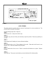
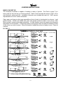
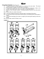
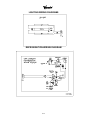
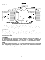
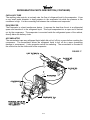
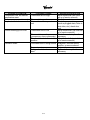
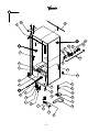
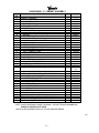
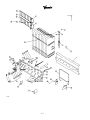
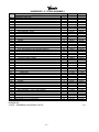
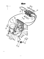
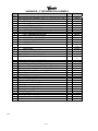
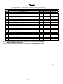
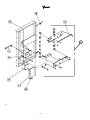
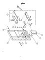
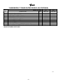
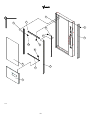
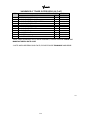
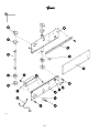
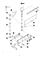
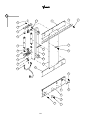
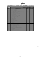
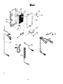
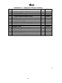
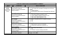
1
INITIAL SET UP
A. UNPACKING
Remove all plastic film, cardboard and tape from the outside of the vendor. Loosen any
shipping devices used to secure interior parts during shipment (backspacer, shims or
spacers).
To remove shipping boards from base, raise vendor on a well stabilized lifting device.
Remove the leveling bolt which hold the boards in place and remove the boards. Replace
bolts to equal heights in the threaded holes.
Another method to remove shipping boards is to split the boards apart. Using a pinch bar, or
a heavy screwdriver and hammer, insert tool into the slots and force the board apart.
B. POSITIONING AND LEVELING
IMPORTANT: Place the vendor (in desired location) at least 3 to 4 inches away from any rear
obstruction. This is for proper air flow through the refrigeration compartment. The system
requires front to rear air circulation for proper operation. Level vendor with leveling bolts. Be
sure all four leveling bolts are supporting the machine.
C.
POWER SUPPLY CONNECTION
CAUTION: DO NOT USE AN EXTENSION CORD!
The Vendor’s power requirements will vary depending upon the country it was purchased for.
To verify the power requirements of the Vendor, check the serial plate located on the hinge
side of the door (see figure 1 on page 3). The power requirements are listed on the serial
plate.
To insure safe operation of the vendor, the vendor’s power supply must be a properly
grounded and polarized outlet. Before plugging the vendor into the outlet, test the outlet to
confirm it will meet the vendors power requirements. If the power supply of the outlet is
different from the power requirements of the vendor, a transformer may be necessary.
If the power requirements are not properly met, contact a licensed electrician and have the
necessary correction made.
Should you require additional information contact a service representative, see parts, sales
and service centers listed on page 13 and 14 of the machine installation and safety manual.
S-1
FIGURE 1
LOCK CODING
The safest method to code the lock is to remove it and secure it in a vise or similar tool. The
lock can also be recoded in the handle.
(For the following steps refer to Figure 2)
STEP 1
Insert key into lock. Insert pin into hole in cap.
STEP 2:
To release cap, push pin in firmly and rotate key to right slot position. Remove cap and key as
one unit.
STEP 3:
Using magnet end of loading tool, remove all seven tumblers.
STEP 4:
Slip preloaded coder on lock. Place loading tool into coder. Coder and tool will mount in one
direction only. Press new tumblers firmly into place.
STEP 5:
Remove coder and tool as one unit. Check to insure that all tumblers are in place. Replace
lock cap.
STEP 6:
Insert New key. Press cap in and rotate key counter clockwise left to locked position.
S-2
S-3
FIGURE 3
FIGURE 4
LABEL INSTALLATION
COIN INSTRUCTION LABEL & PRICE LABEL APPLICATION:
Apply labels to a clean and dry surface. Peel backing from label and apply to plate with a firm
even pressure.
INSTRUCTION LABEL
(Refer to figure 3 for the following information.)
Plate “A” has Validator Opening separate and above the Coin Plate “B” shows the Validator
Opening built in the Coin Plate. Apply Instruction Label to area shown (as needed by the
vendor).
FLAVOR LABELS INSTALLATION:
In figures 4 & 5, corresponding styles are indicated by A, B, C, D, or E notations.
Insert Flavor Labels to the side or top of Selection Window or Button depending on the style.
See Figure 4 for selection style. Rear view of windows and buttons is shown in Figure 5.
Arrows point the direction to insert labels.
Selection Window and Selection Button Labels identify product contained in stack columns.
FIGURE 5
S-4
FIGURE 7
FIGURE
9
ALIGNMENT CHECKS
DOOR ROLLER CHECK:
The Door Roller assembly is raised or lowered by adding or removing shims, (see figure 7 ).
Raising or lowering the roller will help ensure the proper alignment of the door lockstud to the
cabinet latch.
DOOR ALIGNMENT CHECK:
After any door adjustment, the Quicker Lock should align itself automatically. If additional
adjustment is necessary, loosen mounting screws, (see Figure 8), raise or lower latch to the correct
position. Tighten mounting screws the floating nut of the Quicker Lock must be able to engage the
bolt of the T-handle.
REFRIGERATION AREA CHECK:
Check the position of the Condensation Pan, see Figure 9. The correct position of the Condensation
Pan is between the Compressor and the Condenser Fan Bracket. Be sure the Drain tube is clipped
to the pan and free of kinks. A loop must be maintained in the tubing. The loop prevents warm air
from reaching the evaporator area.
FIGURE 8
S-5
TEMPERATURE CONTROL
PRODUCT TEMPERATURE CHECK: (Reference only)
Allow vendor to run 24 hours. Vend product, insert test device (thermometer) into beverage.
TEMPERATURE CONTROL SETTING:
The temperature inside the cabinet is regulated by the Temperature Control, located on the left
side of the Evaporator (see Figure 10 ). Before adjusting control, make sure the refrigeration
system is working properly. Check that all fans run freely and do not make excessive noise.
Check that the vanes of the Evaporator are free of obstructions. Air flow over the vanes is
important for proper operation of the refrigeration unit. Check the door for a tight seal.
When the air temperature at the Capillary tube reaches 39 degrees Fahrenheit, the refrigeration
system will cycle on (see Figure 11). To decrease the temperature, turn the Temperature
Control Screw clockwise (see Figure 10). To increase the temperature, turn the screw counterclockwise. The temperature will change approximately 6 degrees with every 1/4 turn of the
control screw.
The Capillary tube is positioned in the air flow of the evaporator (see Figure 11). It must not
touch the rear of the cabinet wall or the evaporator shield (except at the clip). It is possible to
distort the position of the tube upon replacement and installation. If the refrigeration system is
replaced, check the Capillary tube’s position.
FIGURE 10
FIGURE 11
S-6
LOADING INSTRUCTIONS
BASIC LOAD SET-UP:
The Univendor-2 machine is capable of vending a variety of product. The Chart on page 7 is a
basic guide for the load set-up of these products. Refer to the chart and the items in Figure 12 for
each product’s setting and kits. Installation Instruction are included with each kit. Call a service
representative for kits or further information.
Open upper and lower product cage assemblies at front of stack to load product in columns. Load
product evenly. Bottles are loaded with crown end placed toward the back of the column. After
filling columns, close product cage assemblies. In initial loading, prime the machine by advancing
the product into the buckets. To advance product, insert proper coins and push the selection button
of the column you wish to prime. When the bucket is loaded the column is ready to vend. Prime all
columns.
FIGURE 12
S-7
VEND MECHANISM PARTS DESCRIPTION
The parts listed below are part of the Vend Motor Mechanism (refer to Figure 17 on page A6).
One Mechanism is required per column. The parts are interchangeable. Setting will differ
between single, double or triple depth.
MOTOR: P/N 388637
This motor is a thermal protected, 115 volt, 60 hertz, shaded pole motor. The motor has an
externally mounted spring loaded mechanical brake. The Motor is attached to the Mech. Plate
by three screws.
MOTOR CAM: P/N 390360
The Motor Cam assembly consists of two parts, the Cam and the Cam Retainer The Cam
controls the Motor Carrier and the Start/Bypass Switches. The Cam is Attached to the Motor by
the Cam Retainer (Retainer P/N 389401). The Retainer rotates left or right, provides for single,
double, or triple depth operation. (see page S-7 for Cam Settings)
MOTOR CARRIER SWITCH: P/N 388687
Two switches are located below the Motor Cam. The outside switch is the motor carrier switch.
This switch holds the motor on though the vend cycle. The motor stops when the motor Carrier
switch drops out.
SOLDOUT SWITCH: P/N 368299 / BASE SWITCH: P/N 388303
There is one Soldout Switch and one Base Switch above the Vend motor. The Soldout Switch is
actuated by the Soldout flap when the column is empty. It stops the motor from running. When
all columns are empty the Electronic Control stops the coinage from accepting money.
SELECTION SWITCH: (See part Section of the Manual for P/Ns.)
The selection switch sends power to a Vend Motor when a Customer Presses a Selection
Button. The Selection Switches are beneath the Selection Button/Windows.
VEND BUCKET: P/N 1060139
The Vend Bucket holds the product(s) in a ready to vend position at the base of each column.
ADAPTER COUPLING: P/N 1027042
The Adapter coupling couples the motor to the bucket. It is located behind the motor, on the
motor shaft.
ANTI-TILT CLIP: P/N 389712
The Anti-Tilt Clip prevents product from dropping out of the Bucket if the Vendor is tilted. The
Clip is located in the bucket.
S-8
GATE: P/N 1066082
The gate holds product above the Vend Bucket.
GATE LINK: P/N 1008501
The rotation of Vend Bucket moves the gate link, this opens the gate allowing one layer of product
to drop into the bucket.
GAUGE BAR: P/N 1064333
The Gage Bar Holds the product (s) inside the bucket. It also regulates which product is vended
first when Double or Triple depth setting are used (See page S-7 for setting).
FIGURE 13
ANTI-TILT CLIP
GATE
SOLDOUT LEVER
GATE
LINK
SPRING
SWITCH
MOUNT
BUCKET
GAGE BAR
COUPLING
MOTOR CARRIER SWITCH
MOTOR CAM
S-9
VEND CYCLE
Several operations take place during the Vend Cycle: a purchase is made, the cam and bucket
rotate, product is dispensed and reloaded. The sequence of these operations change slightly
when the column’s depth setting is changed. With the Single Depth Setting, one purchase is
made and the bucket is reloaded, the Cam Sequence occurs once per bucket revolution. With
the Double Depth setting, two purchases are made before the Bucket is reloaded, the Cam
Sequence occurs twice per bucket revolution. With Triple depth setting, three purchases are
made.
PURCHASE SEQUENCE:
PS 1. Customer insert money.
PS 2. The Coinage Unit sends a signal energizing the Credit Relay. This creates a path of
power for the Selection Switch.
PS 3. Customer presses a Selection Button.
PS 4. The chosen Selection Switch closes, creating a path of power to energize a Vend
Motor.
PS 5. The Vend Motor turns the Bucket and Cam.
PS 6. Product is Immediately dispensed.
CAM SEQUENCE: (See Figure 14, Double depth Setting Pictured)
CS 1. As the Motor turns the Cam, the Switch falls into the low part of the cam. This interrupts
the power path to the Credit relay canceling credit.
CS 2. Simultaneously, the Motor Carrier Switch is lifted to the high part of the cam. This
provides an alternate path of power, to the Vend Motor.
CS 3. With the Cam still rotating, the Switch lifts back to the part of the Cam, (permitting
another purchase when it is required).
CS 4. The Motor Carrier Switch falls into the lower part of the Cam, cutting power to the Motor.
The Motor stops.
FIGURE 14
S-10
RELOADING SEQUENCE: (See Figure 15)
RS 1. The gate link rests at a locked position, in a cutout on the mech. plate. This locked
position prevents the gate from opening out of sequence.
RS 2. The gate link is guided by a slot in the mech. plate and actuates by a ridge on the
bucket. As the bucket turns, the link is moved out of the locked position.
RS 3. As the link rises, the gate is opened. The spring maintains Pressure on the Link and the
gate.
RS 4. Product falls onto outside of the bucket.
RS 5. The bucket releases the gate link causing the gate to rest against the product.
RS 6. As the product falls into the bucket, the link returns to the locked position and the gate is
closed.
RS 7. The product remaining in the column is caught by the closed gate, keeping it above the
bucket.
RS 8. Bucket stops, product is Ready to vend.
FIGURE 15
S-11
LIGHTING WIRING DIAGRAMS
REFRIGERATION WIRING DIAGRAM
S-12
REFRIGERATION OPERATION
The refrigeration operation section is divided into three areas: Basic Refrigeration Principle.
Detailed Vending machine Refrigeration cycle, and Parts Description.
BASIC REFRIGERATION PRINCIPLE
What a refrigeration system really accomplishes is the transfer of heat. A refrigeration system
removes the excess heat from a refrigerated area and then transfers it to a condenser where it is
dissipated. As heat is removed, the refrigerated area cools.
In vending machines, large quantities of the heat must be transferred rapidly, economically and
efficiently. This process must be able to withstand continuous repetition, without loss of refrigerant,
over an extended period. The most common system used in the vending industry is the vapor
compression (or simple compression) cycle system. It consists of four basic elements: an
evaporator, a compressor, a condenser, and a pressure reducing restricted (all part of a sealed
system).
The compression system operates at two pressure levels: the low evaporating pressure and the
high condensing pressure. The refrigerant acts as the transport medium, in which heat is moved
from the evaporator to the condenser; at the condenser, the heat is dissipated into the surrounding
air.
The liquid refrigerant changes from a liquid, to a vapor and back to a liquid again. This change of
state allows the refrigerant to absorb, and rapidly discharge, large quantities of heat efficiently.
BASIC VAPOR COMPRESSION SYSTEM CYCLE DESCRIBED:
In the evaporator the liquid refrigerant vaporizes. This change occurs at a temperature enough to
absorb heat from the refrigerated space. The temperature of vaporization is controlled by the
pressure maintained in the evaporator (the higher the pressure, the higher the vaporization point).
The compressor pumps the vapor from the evaporator, through the suction line, and to the
condenser. The compressor takes the low pressure vapor and compresses it, increasing both the
pressure and the temperature. The compressor pumps the vapor at a rate rapid enough to maintain
the ideal pressure. The hot high pressure vapor is forced out of the compressor, into the discharge
line and then into the condenser.
Air is blown through the condenser, allowing heat to transfer from the condenser and into the
passing air. As the heat is removed, the stored refrigerant is condensed into a liquid. The liquid
refrigerant is stored in the lower tube of the condenser. It is there, available to flow through the
restricter tube, back into the evaporator, where the refrigeration cycle is repeated.
S-13
DETAILED REFRIGERATION CYCLE
The following is a detailed refrigeration cycle as it applies to the refrigeration system installed in
Vendo equipment. (Refer to the flow chart in Figure 16)
As the temperature in the cabinet rises, the liquid in the thermostat feeler bulb also rises in
temperature. As this liquid becomes warmer, it expands. This expanding liquid expands against
the temperature control bellow which operates the temperature control switch. The temperature
control switch turns on both the compressor and condenser fan.
The evaporator fan pulls air from the front of the refrigerated space of the cabinet. It pulls the air
through the evaporator, and blows it up the back of the vend stack. (The evaporator fan runs
continuously.) As the air passes through the evaporator, heat is draw from the air and
transferred to the liquid refrigerant. As the cooled air circulates through the vend stack, heat is
drawn from the product and transferred to the circulating air. The heated air is again drawn
through the evaporator where the heat is removed.
In the evaporator, the liquid refrigerant draws heat from the circulating air.
receives heat, it vaporizes.
As refrigerant
The compressor pumps the vapor from the evaporator and compresses it (increasing both
pressure and temperature). The compressor forces the compressed vapor out, through the
discharge line and into the condenser.
The condenser fan pulls air through the condenser. As the hot refrigerant vapor passes through
the condenser tubes, heat is drawn from the vapor. This heat is dissipated into the passing air,
the air then exits out the back of the vendor. As the refrigerant vapor in the condenser lines is
cooled, it returns to a liquid state.
From the condenser the liquid flows to the drier. The drier removes any water and solid particles
from the liquid refrigerant.
The cooled liquid refrigerant continues from the drier, through the capillary tube, to the
evaporator. The capillary tube steadies the flow rate of the refrigerant. Its small inside diameter
allows the pressure in the evaporator to remain low while the pressure in the condenser is high.
The cool refrigerant in the evaporator draws heat from the circulating air in the cabinet. As the
temperature in the cabinet drops, the liquid in the thermostat feeler bulb cools and condenses.
The condensed liquid releases the pressure against the thermostat control bellows, de-actuating
the temperature control switch. The deactuated control switch turns off the compressor and
condenser fan.
When the temperature in the cabinet rises above the thermostat’s setting, the compressor and
the condenser fan engage again. The refrigeration process is continuous as long as the
compressor operates.
S-14
FIGURE 16
REFRIGERATION PARTS DESCRIPTION
The Compressor, Condenser, Drier, Capillary Tube, Evaporator, and Accumulator are part of
a sealed system (refer to figure 16). These items are not available separately. For the part
number of the sealed refrigeration system refer to the common parts section of the manual.
COMPRESSOR
The compressor takes in low pressure vapor and compresses it, increasing both the pressure and
the temperature. The hot high pressure gas is forced out to the condenser. The compressor and
the motor that drives the compressor are sealed inside a housing. The compressor, as a unit, is
mounted on the refrigeration base. The base is mounted in the bottom of the vendor, outside the
sealed refrigeration space.
CONDENSER
The condenser takes heat out of the high pressure vapor that it receive from the compressor. As
the vapor passes through the condenser it cools and returns to a liquid state. The condenser is
mounted to the refrigeration base near the front of the vendor. It is easily accessible for cleaning.
DRIER
The Drier is a molecular sieve strainer drier. It removes water and solid particles from refrigerant
liquid. One side of the dryer is connected to the outlet line of the condenser; the other side is
connected to the capillary tube going to the evaporator.
S-15
REFRIGERATION PARTS DESCRIPTION (CONTINUED)
CAPILLARY TUBE
The capillary tube controls, at a steady rate, the flow of refrigerant liquid to the evaporator. It has
a very small inside diameter to keep pressure in the evaporator low while the pressure in the
condenser is high. It is the connecting link between the condenser and evaporator.
EVAPORATOR
The Evaporator is a heat transference device. It removes the heat from the air in a refrigerated
space and transfers it to the refrigerant liquid. This liquid evaporates into a vapor and is sucked
out by the compressor. The evaporator is mounted inside the refrigerated space of the cabinet,
directly below the delivery chute.
ACCUMULATOR
The accumulator traps any refrigerant liquid which did not boil off into a vapor before reaching the
compressor. The accumulator allows the refrigerant liquid to boil off as a vapor (preventing
damage to compressor). It also prevents suction line sweating. The accumulator is mounted in
the suction line on the outline side of the evaporator.
FIGURE 17
S-16
(The parts listed below are not part of the sealed refrigeration system and are available separately.
For part numbers, see the refrigeration assembly in the common parts section of the manual.)
CONDENSER FAN ASSEMBLY
The condenser fan pulls cool air from outside the vendor, through the condenser, over the
compressor and blows it out the back of the vendor. This cool air removes excess heat from
refrigerant in the condenser. The condenser fan runs when the compressor is engaged. The fan
assembly is mounted on the refrigeration base between the condenser and compressor.
EVAPORATOR FAN ASSEMBLY
The Evaporator fan pulls air from the front of the refrigerated space, through the evaporator, up the
rear of the refrigerated space into the vend stack. The fan blows air through the evaporator (which
removes the heat from the air). It circulates the cool air over the product, removing excess heat
from the product. The evaporator fan assembly is mounted to a fan bracket, mounted to the
extensions of the evaporator. These parts are located in the refrigerated area of the cabinet.
TEMPERATURE CONTROL
The temperature control regulates the temperature inside the refrigerated space of the vendor. The
control is adjustable. The temperature control consist of two main parts: the temperature control
box and the thermostat feeler bulb. The control box is mounted to the side of the evaporator. The
bulb is mounted on the evaporator fan bracket, in the air flow of fan. The bulb is a very narrow tube
with a refrigerant liquid inside. Small tubing connects the bulb to the control box. As liquid in the
feeler bulb warms, it expands into the tubing and then into the control box, pressing against a
bellows. The bellows closes a switch in temperature control, activating the compressor and the
condenser fan. As the liquid in the feeler bulb cools it contracts and releases the pressure against
the bellows, opening the switch, deactivating the compressor and the condenser fan.
START CAPACITOR - (WHEN USED)
The start capacitor is used on start up of the refrigeration system to phase out excess power to and
from the refrigeration system.
STARTING RELAY
The starting relay is mounted in the terminal box on the side of the compressor housing. When the
compressor first starts up, the starting relay closes and completes a starting circuit. When the
compressor motor reaches operating speed, the starting relay opens and breaks the starting circuit.
THERMAL OVERLOAD SWITCH
The thermal overload switch is mounted in the terminal box on the side of the compressor housing.
If the compressor motor gets hot or draws too much current, the thermal overload opens and breaks
the starting and running circuit of the motor. As the motor cools, the thermal overload closes,
allowing the compressor to run.
S-17
MAINTENANCE
The following section is a basic guide for general maintenance and servicing of the Vendor . This
section is divided into four parts: (I) Preventative Maintenance, (II) Lubrication Guide, (III) Care
and Cleaning, (IV) Basic Trouble Shooting.
I.
PREVENTATIVE MAINTENANCE SUGGESTIONS:
When ever a Vendor is visited on its site, the following service should be performed.
Preventative maintenance will help prevent future problems with the Vendor.
A.
B.
C.
D.
E.
F.
G.
H.
I.
J.
K.
L.
M.
II.
Observe the Vendor and its surrounding area for any unusual indications of problems
(rear on cabinet, obstructions of the air flow, dark spots on the sign face, etc.)
Open the door and visually check the inside of the Vendor (water accumulation, rust
marks, moisture around the edges of the inner door, etc.)
Check the fluorescent lamps, replace as necessary. Replace single pin (slimline) lamps
within 24 to 48 hours of burnout. This will prevent damage to ballast.
Check the product temperature for proper cooling.
Check evaporator drain for obstruction; water in the evaporator area must drain to the
condensate pan.
Empty condensate pan.
Clean the condenser, free vanes of dirt, lint, etc.
Check evaporator fan(s) run normally.
Check the Compressor and condensate fan run normally.
Investigate any unusual sounds (fan blades hitting something, refrigeration lines rattling,
etc.)
Clean coin acceptor.
Deposit all coinage accepted by the Vendor to check for proper operation of the coinage
mechanism.
Test the Vendor and make a report on the problems,
LUBRICATION GUIDE:
Lubricate indicated areas as directed on the chart below.
INTERVALS
PARTS
Every six months
Top hinge of door door hinge
pin at the base of cabinet door
latch cam to cabinet strike Thandle shaft & latch.
As necessary
Pivot area of bucket and gate
S-18
LUBRICANT
Grade two, high low
temperature grease
Grade two, high low
temperature grease
III.
CARE AND CLEANING
A.
GENERAL PROCEDURE ( painted metal areas)
Wash Vendor with soap and water. The exterior may be waxed with any good
automobile wax.
B.
FRESH PAINT SPLASHES, GREASE, GLAZING COMPOUND REMOVAL
Before drying, these elements may be removed by rubbing lightly with grade “A” Naptha
(or equivalent grade solvent). After removal, use general cleaning procedure (listed
above as A)
C.
LABELS AND STICKER REMOVAL
Use Kerosene, VM&P grade Naptha or petroleum spirits for removal. When the label
material does not allow penetration of solvent (such as vinyl) the application of heat
(hair blow dryer) will soften the adhesive and promote removal. CAUTION: Excessive
heat can cause surface damage. After the label is removed, use the general cleaning
procedure (listed above as A).
D.
SCRATCH REMOVAL
Remove or minimize hairline scratches and minor abrasions by using any good quality
automobile polish. Test product before using.
E.
LEXAN SIGNS
To clean Lexan sign faces the following procedure is recommended.
1. Wash sign with mild soap or detergent and lukewarm water.
2. Using soft cloth or sponge, gently wash the sign. DO NOT SCRUB!
3. Rinse well with clean lukewarm water.
4. Dry thoroughly with a chamois or cellulose sponge (to prevent water spotting). DO
NOT USE SQUEEGEE!
NOTE:
F.
Most organic solvents, petroleum, spirits, or alcohol are NOT compatible cleaning
materials for lexan signs. Usage of those materials could permanently damage the
sign.
REFRIGERATION AREA
The condenser and evaporator must be kept clean for efficient operation. Be sure all
vanes and tubing are clean and clear of obstruction; This allows free passage of air.
Clean with a brush, a vacuum cleaner or compressed air. Keep cabinet drain open;
clean as necessary.
S-19
TROUBLE-SHOOTING GUIDE
This guide is a general list of probable problems, causes, and solutions. For problems
not listed or additional question, contact the Field Service Department at Vendo, 7209
N. Ingram Ave., Fresno, CA 93650 or call 1-800-344-7216. Please have the
maufacturer’s date code and model number of the vendor when you call.
The trouble-shooting guide is divided into three columns: First Column, Possible
Problem; Second Column, Possible Cause; Third Column, Service Suggestion.
POSSIBLE PROBLEMS
Returns all good coins
POSSIBLE CAUSE
No power to vendor
No power to changer
SERVICE SUGGESTION
Check power Supply
Check coin mechanism plugs
check for faulty harness wiring
(see wiring diagram for circuit)
Acceptor is out of adjustment or Check coin mechanism
coin gate is not closed
Electronic-CREM function: 1.) 1. Check electrical connections
No power to acceptor.
of the acceptor.
2.) Defective acceptor
2. Replace acceptor
Coin paths are dirty
Clean acceptor with approved
cleaner. DRY VERY
THROUGHLY
S-20
POSSIBLE PROBLEM
Money accepted no product
vended
POSSIBLE CAUSE
No selections work
No. 1 selection works, No. 2
thru last does not.
Soldout Switch (of column
selected) inoperative
Motor starts, does not run
Vend motor runs until two or
three products are vended or
vend motors run continuously.
Refrigeration unit will not run
at all
Compressor will not start
SERVICE SUGGESTION
Check No.1 selection switch,
replace if necessary.
Check No 2. section switch,
replace it necessary. This
pattern can continues thru last
selection switch as selection
circuit goes from 1 to 2 to 3.
etc., to last
Check switch, replace
Check motor carrier switch,
replace switch
Improper cam lobe adjustment Check Cam for proper
arrangement of cam lobes
(see product set up guide)
Motor carrier switch not
Check lever for proper lever
making contact with cam lobe positioning and freedom of
or switch
movement
No power to vendor
Check power supply also
check service cord
connections.
Thermostat open (temperature Check thermostat (Apply
control)
insulated jumper across
terminals, if compressor starts,
replace thermostat)
Temperature control bulb out
Check that bulb is in air flow
of position
Overload Protector
Check overload (apply
Inoperative
insulated jumper across
terminal, if compressor starts,
replace overload)
Compressor will not start
condenser fan motor running,
unit cool (no power to
compressor)
POSSIBLE PROBLEM
Compressor will not start,
POSSIBLE CAUSE
Starting relay or capacitor
S-21
SERVICE SUGGESTION
Check relay or capacitor
condenser fan motor running - inoperative
unit hot (power to compressor)
Compressor inoperative
Compressor starts but does
not run
Will not cycle
Starting relay stays closed
Thermostat inoperative
Compressor runs but cabinet
temperature warm
Compressor motor problem
Loss of refrigerant
Condenser fan not working
Blocked or dirty condenser
(refer to initial installation in
the service manual)
Evaporator fan not working
Bad inner door seal
S-22
replace
Disconnect power to vendor,
remove all leads from
compressor, check continuity
from “common”, “start” and
“run” to compressor case. If
continuity shows, replace
compressor. Also Check from
“common to start”. (using
continuity or IHMS.) If meter
fails to show reading replace
compressor.
Check overload and contact,
replace overload if necessary
Replace relay
Check thermostat clean
contacts with approved
electrical cleaner. Replace
thermostat it necessary
Check, replace
Replace refrigeration unit
(Note: any work of this nature
done without express
permission from The Vendo
Company can void
refrigeration unit warranty)
Check circuit to run motor.
Replace motor. Check for
obstruction of fan blade.
Check condenser vanes for
obstruction, lint or dirt. Clean,
also check for proper air flow
through refrigeration area.
Check circuit to fan motor.
Replace motor also check for
obstruction of fan blade
Check for moisture on seal.
Adjust inner door as
necessary (see initial setup of
service manual). Replace
door seal.
POSSIBLE PROBLEM
Compressor runs, but cabinet
temperature warm
Compressor runs continuously
Evaporator frosted over
Product freezing up too cold
Excessive noise
POSSIBLE CAUSE
Thermostat set too high
SERVICE SUGGESTION
Adjust thermostat (see initial
set up of service manual)
Thermostat inoperative
Check thermostat
Water at base of evaporator
Check for proper drainage
unit
(such as plugged drain, kinks in
drain tube, etc.) check door
seal
Thermostat set too low
Adjust thermostat (See intial set
up of service manual)
Thermostat inoperative
Check thermostat replace if
(compressor runs continuously) necessary
Thermostat feeler bulb out of
Adjust feeler bulb (see initial set
position
up of service manual)
Fan blade bent or hitting shroud Straighten, relocate shroud
position, or remove shroud.
Fan motor noisy
Replace if necessary
Refrigeration base loose or
Tighten bolt or replace if
bent
necessary
S-23
A COMMITMENT TO SAFETY
The Vendo Company is committed to safety in every aspect of our product design. Vendo
is committed to alerting every user to the possible dangers involved in improper handling
or maintenance of our equipment. The servicing of any electrical or mechanical device
involves potential hazards, both to those servicing the equipment and to users of the
equipment. These hazards can arise because of improper maintenance techniques. The
purpose of this manual is to alert everyone servicing Vendo equipment of potentially
hazardous areas, and to provide basic safety guidelines for proper maintenance.
This manual contains various warnings that should be carefully read to minimize the risk
of personal injury to service personnel. This manual also contains service information to
insure that proper methods are followed to avoid damaging the vendor or making it unsafe.
It is also important to understand these warnings are not exhaustive. Vendo could not
possibly know, evaluate, or advise of all of the conceivable ways in which service might be
done. Nor can Vendo predict all of the possible hazardous results. The safety precautions
outlined in this manual provide the basis for an effective safety program. Use these
precautions, along with the service manual, when installing or servicing the vendor.
We strongly recommend a similar commitment to safety by every servicing organization.
Only personnel properly trained in vendor servicing should have access to the interior
of the machine. This will minimize the potential hazards that are inherent in electrical and
mechanical devices. Vendo has no control over the machine once it leaves the premises.
It is the owner or lessor’s responsibility to maintain the vendor in a safe condition. See
Section I of this manual for proper installation procedures and refer to the appropriate
service manual for recommended maintenance procedures. If you have any questions,
please contact the Technical Services Department of the Vendo office nearest you. Refer
to the listing at the back of this manual.
SAFETY RULES
•
•
•
•
•
•
•
•
Read the Safety Manual before installation or service
Test for proper grounding before installing to reduce the risk of electrical shock and fire.
Disconnect power cord from wall outlet before servicing or clearing product jams. The
vending mechanism can trap and pinch hands.
Use only fully trained service technicians for “Power On” servicing.
Use adequate equipment when moving a vendor.
Always wear eye protection, and protect your hands, face, and body when working
near the refrigeration system.
Use only authorized replacement parts.
Be aware of inherent dangers in rocking or tipping a vending machine.
Page 1
SECTION I: VENDOR INSTALLATION
A.
Vendors are large, bulky machines of significant size and weight. Improper
handling can result in injury. When moving a vendor, carefully plan the route to be
taken and the people and equipment required to accomplish the task safely.
B.
Remove all tape, shipping sealant, and Styrofoam from the vendor. Loosen any
shipping devices used to secure interior parts during shipping. Remove the wooden
shipping base, attached to the vendor base by the vendor leveling screws. Make
certain the leveling screws are in place and functional.
C.
Position the vendor three to four inches (7.6 cm to 10.2 cm) from a well-constructed
wall (of a building or otherwise) on a flat, smooth surface.
IMPORTANT: The vendor requires three inches (7.6 cm) of air space from the wall
to ensure proper air circulation to cool the refrigeration unit.
D.
Adjust the leveling screws to compensate for any irregularities on the floor surface.
Ideally, no adjustment will be necessary and the leveling legs will be flush with the
bottom of the vendor. A spirit level is a useful aid to level the vendor. When the
vendor is properly leveled, the outer door, when opened, will remain stationary.
Vendors must be level to assure proper operation and to maintain stability
characteristics. Do not add legs to the vendor.
E.
Check the manufacturer’s nameplate on the left or right side of the vendor outer
door to verify the main power supply requirements of the vendor. Be sure the main
power supply matches the requirements of the vendor. To ensure safe operation,
plug the vendor only into a properly grounded outlet. DO NOT USE EXTENSION
CORDS.
NOTE:
Any power supply variance more than + 10% may cause vendor to malfunction.
*
Power outlets must be properly grounded.
*
Power outlets must be properly polarized, where applicable.
Test the outlets using the following information. (Refer to Figure 1 on Page
3.)
Page 2
Page 3
SECTION I: VENDOR INSTALLATION (CONT’D)
For Type 1 and Type 2 outlets, test for Grounding and Polarization as follows:
1.
With a test device (volt meter or test light), connect one probe to the receptacle’s
Neutral contact and the other to the Live contact. The test device should show a
reaction.
2.
Connect one probe to the receptacle’s Earth contact and the other to the Live
contact. The test device should show a reaction.
For Type 3 through Type 5 outlets, test for Grounding as follows:
1.
2.
With a test device (volt meter or test light, determine which of the receptacle’s
Power contacts is the Live contact.)
A.
Connect one probe to the receptacle’s Earth contact.
B.
Connect the second probe to the left (or upper) Power contact. If a reaction
occurs, this is the Live Power contact. If a reaction does not occur, move the
second probe to the right (or lower) contact. A reaction should occur,
indicating that this is the Live Power contact.
Connect one probe to the receptacle’s Live Power contact (as determined in step
1). Connect the second probe to the other Power contact (neutral). The test device
should show a reaction.
IF THE ABOVE CONDITIONS ARE NOT MET FOR THE GIVEN
OUTLET TYPE, CONTACT A LICENSED ELECTRICIAN AND
HAVE THE NECESSARY CORRECTIONS MADE.
F.
Ambient temperature operating range for this vendor is +5°F to +113°F (-15°C to
+45°C). The climatic rating of this vendor is “N” (Normal).
Page 4
SECTION I: VENDOR INSTALLATION (CONT’D)
G.
Door Support (Fig. 2)
The door support may be raised or lowered
by adding or removing shims, to insure that
the outer door closes squarely to the cabinet.
Raising or lowering the door support can also
insure proper alignment of the door latch.
FIGURE 2
H.
Door Latch Alignment (Fig. 3)
After any door adjustment, the floating
Quicker Lock assembly should align itself automatically. The latch assembly is
adjustable. To adjust, loosen the latch bracket mounting screws, and raise or lower
the latch assembly into position, then tighten the mounting screws.
FIGURE 3
FIGURE 4
WARNING:
KEEP FINGERS AND OTHER OBJECTS OUT OF LOCK CAVITY
NOTE:
Refer to the Appropriate Parts and Service Manual for Detailed
Instructions, Operating Principals, and Recommended Maintenance
Intervals and Procedures.
Page 5
SECTION II: ELECTRICAL HAZARDS
GENERAL
Vendo vending machines are provided with the appropriate power supply setting for your
area. Some models are equipped with step-down transformers, as required, enabling the
vending machines to operate on different mains voltages. Refer to section I. E. for
information to determine the main power requirements. Refer to the appropriate Service
Manual for details of step-down transformer operation.
The power sources mentioned above are standard for both household and commercial
lighting and appliances. However, careless or improper handling of electrical circuits can
result in injury or death. Anyone installing, repairing, loading, opening, or otherwise
servicing a vending machine should be alerted to this point. Apply all of the normal
precautions observed in handling electrical circuits, such as:
•
•
•
•
•
•
A.
Refer servicing to qualified personnel only.
Unplug the vendor before servicing or clearing product jams.
Replace electrical cords if there is any evidence of fraying or other damage.
Keep all protective covers in place.
Plug equipment into outlets that are properly polarized (where applicable), and
protected with fuses or circuit breakers.
All electrical connections must be dry and free of moisture before applying power.
Grounding Systems
Vendo vending machines are provided with the appropriate service cord for the
power supply in your area. The service cord will connect to the matching electrical
outlet. Always ensure that the outlet to be used is properly grounded (and polarized
where applicable) before plugging in the vendor. (See pages 3 and 4).
WARNING:
ALWAYS TEST TO VERIFY PROPER GROUNDING PRIOR TO
INSTALLATION, IN ORDER TO REDUCE THE RISK OF ELECTRICAL
SHOCK AND FIRE
The electrical grounding system also includes the bonding of all metal components within
the vendor. This involves a system of bonding wires identified by green or green and
yellow marking. The system uses serrated head screws, lock washers, and star washers
to assure the electrical connection between parts. Maintenance of vending equipment
may involve disassembly. Include the above items when reassembling, even if the
vending machine may appear to function normally without them. Omitting any of these
items can compromise a link in the grounding system. See the appropriate Service
Manual or kit instructions for components and assembly instructions.
Page 6
SECTION II: ELECTRICAL HAZARDS (CONT’D)
B.
Servicing with “Power Off”
For maximum safety, unplug the service cord from the wall outlet before opening
the vendor door. This will remove power from the equipment and avoid electrical
and mechanical hazards. Service personnel should remain aware of possible
hazards from hot components even though electrical power is off. See the
appropriate sections of this manual for further information.
C.
Servicing with “Power On”
Some service situations may require access with power on. Power-on servicing
should be performed only by fully qualified service technicians. Particular caution
is required in servicing assemblies that combine electrical power and mechanical
movement. Sudden movement (to escape mechanical action) can result in contact
with live circuits and vice versa. It is therefore doubly important to maintain
maximum clearances from both moving parts and live circuits when servicing.
WARNING:
“POWER-ON” SERVICING SHOULD BE ACCOMPLISHED ONLY BY
FULLY TRAINED PERSONNEL. SUCH SERVICE BY UNQUALIFIED
INDIVIDUALS CAN BE DANGEROUS.
NOTE:
For Power-On servicing of vendors with a door power switch, it is necessary to
activate the switch when the outer door is open. This is accomplished by one of
the following methods:
1.
Straight Plunger Switch: Pull plunger forward.
2.
Protected Plunger Switch:
plunger inward.
Place key (provided) in position to hold
Page 7
SECTION III: MECHANICAL HAZARDS
A.
Servicing of Moving Parts and Assemblies
When servicing assemblies involving moving parts, use extreme caution!! Keep
fingers, hands, loose clothing, hair, tools, or any foreign material clear of
entrapment.
As noted before under the Electrical Hazards section, “Power On” servicing should
only be performed by qualified personnel. Refer to and heed the warnings noted in
Electrical Hazards section.
These warnings refer to the potential hazards
associated with electrical power and moving parts. Always maintain maximum
clearances from electrical and moving parts.
Always install protective covers and guards when reassembling equipment.
B.
Product Conversions
See the Service Section of the appropriate Service Manual for stack (or module)
conversion procedures. Improper installation of product shims or spacers can
result in product jams.
WARNING:
ALWAYS UNPLUG OUTLET CORD BEFORE ATTEMPTING TO CLEAR
PRODUCT JAMS, TO PREVENT ENTRAPMENT OF HANDS IN
MECHANISM.
WARNING:
THIS VENDING MACHINE INCLUDES MECHANICAL EQUIPMENT WHICH
CAN BE HAZARDOUS IF IMPROPERLY HANDLED OR SERVICED.
USE CAUTION AND CONSULT THE VENDO SAFETY MANUAL AND THE
VENDO SERVICE MANUAL FOR ADDITIONAL SAFETY INFORMATION
Page 8
SECTION IV: REFRIGERATION HAZARDS
GENERAL
Refrigeration systems involve both electrical power and mechanical action. These
systems may present any of the potential dangers shown in the sections on Electrical and
Mechanical Hazards contained in this manual. See Sections II and III for further
information.
A.
Compressed Refrigerant
Refrigeration systems involve the compression and evaporation of gases. The
pressures contained represent a potential hazard if suddenly released in confined
areas. Caution is required when performing maintenance tests or repairs. All
testing of sealed refrigeration systems should be done by trained personnel who are
familiar with the systems and pressures involved.
B.
Physical Protection
The accidental release of refrigerant gases can result in physical injuries. Always
wear protective glasses and protect your hands, face, and body when working near
the refrigeration system.
WARNING:
ALWAYS WEAR EYE PROTECTION AND PROTECT YOUR HANDS,
FACE, AND BODY WHEN WORKING NEAR THE REFRIGERATION
SYSTEM.
SECTION V: TEMPERATURE HAZARDS
GENERAL
Maintenance personnel should be alert to the potential hazards from hot metal surfaces.
High temperatures may be present throughout the refrigeration system although electrical
power has been removed
Page 9
SECTION VI: SUBSTITUTIONS AND MODIFICATIONS
GENERAL
Unauthorized changes or the substitution of unauthorized parts can compromise the
equipment designs. This can result in unsafe conditions for either the service personnel or
the equipment users. Always refer to the appropriate Parts and Service Manual for
replacement parts and maintenance instructions. If questions arise, contact the Technical
Services Department of the Vendo office in your area. (Consult the listing at the end of
this manual.)
When servicing the vending machine, always reassemble all components to their original
location and position. Maintain the correct routing for tubing, electrical wiring, etc.
Replace all clamps, brackets, and guides to their original locations. Replace all tubing,
sleeving, insulating material, and protective covers to their original condition.
WARNING:
VENDO EQUIPMENT HAS BEEN PROVIDED WITH APPROPRIATE
PROTECTIVE DEVICES TO PROTECT AGAINST THE POSSIBILITY OF
OVERHEATING AND FIRE, AS A RESULT OF EQUIPMENT OR
COMPONENT FAILURES. SUBSTITUTION, MODIFICATION, OR
BYPASSING OF SUCH PROTECTIVE DEVICES CAN CREATE
DANGEROUS CONDITIONS. PROTECTIVE CIRCUITS SHOULD NEVER
BE BYPASSED, AND FAILED PROTECTIVE DEVICES MUST BE
REPLACED ONLY WITH FACTORY-AUTHORIZED PARTS.
A.
Service Cord Replacement
Vendo vending machines are furnished with unique power supply cords. If
replacement becomes necessary, consult the appropriate Parts and Services
Manual and order the correct replacement cord for the model of vending machine in
question. Do not use substitute replacement cords. Only authorized service
personnel with appropriate training should replace the vending machine service
cord. If a question should arise concerning which service cord to order, contact the
Technical Services Department of the Vendo office in your area for assistance.
Page 10
SECTION VI: SUBSTITUTIONS AND MODIFICATIONS (CONT’D)
B.
Service Cord Replacement (For 240 Volt System Used in the United Kingdom)
As the color of the wires in the mains lead of the vending machine may not
correspond with the colored markings identifying the terminals in your plug, proceed
as follows:
The wire which is colored Green and Yellow must be connected to the
terminal in the plug which is marked with the letter E or by the earth symbol or
colored Green or Green and Yellow.
The wire which is colored Blue must be connected to the terminal which is
marked with the letter N or colored Black.
The wire which is colored Brown must be connected to the terminal which is
marked with the letter L or colored Red.
Should the plug on the flexible cord not be the type for your socket outlets, do
not use an adapter, but remove the plug from the cord and discard. Carefully
prepare the end of the supply cord and fit a suitable plug.
WARNING:
THIS APPLIANCE MUST BE EARTHED
IMPORTANT
The wires in the mains leads are colored in accordance with the following code:
Green and Yellow ............................................ Earth
Blue .................................................................. Neutral
Brown............................................................... Live
Page 11
SECTION VII: CONSUMER SAFETY WARNING
WARNING:
VENDOR CAN BE OVERTURNED IF SUFFICIENT FORCE IS APPLIED,
AND MAY RESULT IN SERIOUS INJURY OR DEATH.
GENERAL
There have been incidents, including fatalities, when vending machines have been
vandalized by being pulled over in an attempt to obtain free product or money.
To warn of the danger involved in tipping, shaking, or rocking the vending machine, a
decal has been designed to be affixed to vending machines. (One such decal is supplied
with the vending machine.) Vendo will supply sufficient decals to be placed on all
machines, on request. If you have any questions, contact the Vendo office in your area.
(Consult the listing at the end of this manual.)
THE FOLLOWING DECAL SHOULD BE PLACED IN A POSITION ON THE
VENDOR CONTROL PANEL AT EYE LEVEL.
Page 12
PARTS, SALES, & SERVICE CENTERS OF VENDO/SANDEN COMPANY
AREA
ADDRESS
PHONE NUMBERS
United States, Canada
The Vendo Company
Tel: (209) 439-1770
7209 N. Ingram
Fax: (209) 439-2083
Fresno, CA 93650 U.S.A.
Japan
Sanden International Corporation
Tel: (03) 3835-1321
31-7 Taito 1-Chome
Fax: (03) 3835-3169
Taito-ku
Tokyo 110, Japan
Europe, Mid-East,
Vendo GMBH
Tel: (211) 746012
Africa, U.S.S.R.
Spangerstr. 22
Fax: (211) 7488541
D-40599 Dusseldorf
Germany
Australia,
Sanden International Pty. Ltd.
Tel: 2-7910999
New Zealand
54 Allingham St., Condell Park
Fax: 2-7919029
N.S.W. 2200
Australia
Singapore, Hong Kong,
Sanden International (Singapore) Pte.,
Tel: 4825500
Indonesia, Philippines,
Ltd.
Fax: 4825039
India
Sanden House, 25, Ang Mo Kio st. Y5
Singapore 2056
The Republic of Singapore
Taiwan
Sanden International Taiwan Corp.
Tel: 2-751-2266
7th Floor, No. 16, Alley 56, Lane 181
Fax: 2-731-3903
Sec. 4 Chunghsiao E. Rd., Taipei
Taiwan, Republic of China
Belgium
N.V. Vendo Benelux, S.A.
Tel: (2) 2682595
Industrial Research Park N.O.H.
Fax: (2) 2682862
St. Lendriksborre 13
Font St. Landry
B-1120 Brussels
Belgium
England
Vendhall, Ltd.
Tel: (01256) 479309
Unit 17, The Basingstoke Centre
Fax: (01256) 844469
Westham Lane, Worting Rd, Basingstoke
Hants RG22, 6NQ
Great Britain
Italy
Vendo Italy S.p.A.
Tel: (142) 76391
Casella Postale 9
Fax: (142) 562348
1-15033 Casale Monferrato
Italy
Spain
Vendo Iberia, S.A.
Tel: (03) 4741555
C/C Sant Ferran No. 92
Fax: (03) 4741842
Poligono Industrial la Almeda
E-08940 Cornella (Barcelona), Spain
Page 13
PARTS, SALES, & SERVICE CENTERS OF VENDO/SANDEN COMPANY
FOR LATIN AMERICA
AREA
Mexico
Central America
Chile
Brazil
South America
ADDRESS
Vendo de Mexico
Camino Real de Toluca No. 154
Col. Bellavista
01140 Mexico D.F. Mexico
Midland Inter-American, Inc.
700 West 48th Street
Kansas City, MO 64112 U.S.A.
Sidex
San Juan 4519 - San Joaquin
Santiago de Chile
Cimaq Industria e Comercio de Maq,
Ltda.
Estrada Uniao e Industria, 9.120 Itaipava
25730-730 Petropolis
Rio de Janeiro, Brazil
The Vendo Company
7209 N. Ingram Ave.
Fresno, CA 93650 U.S.A.
Page 14
PHONE NUMBERS
Tel: (525) 515-9745
Fax: (525) 277-0111
Tel: (816) 561-5788
Fax: (816) 531-5544
Tel: (562) 553-1001
Fax: (562) 552-1982
Tel: (55242) 22-2666
Fax: (55242) 22-3244
Tel: (209) 439-1770
Fax: (209) 439-2083
READING A PARTS LIST
I
ITEM NUMBER is found in two locations:
A. It is on the drawing plate, and identifies the part and its location;
B. The same number is in the parts lists and ties the two together.
II
PART NUMBER is the part number that has been assigned to a specific part by
Vendo, for easier identification.
III
QUANTITY REQUIRED relates to the amount required of a part, or will be indicated by
“A/R” as required to attach it to another part.
IV
PART NAME AND DESCRIPTION is the general description for the part, for easier
identification when ordering a like part.
The example below will show how the parts are listed in the parts lists:
1.
VEND MOTOR ASSEMBLY: This is the main assembly named, and any replaceable
parts will be indented below the assembly.
2.
RETAINER CAM: This is an individual part, and will be indented. These indented
parts can be ordered separately, so you do not need to order the entire assembly.
3.
Whenever an assembly is ordered, all the parts that are indented will be included in the
assembly. Any hardware will be listed next to their corresponding parts.
4.
Any parts that may be ordered separately will not have any indented parts listed below
them.
“UNIVENDOR-2” VEND MOTOR ASSEMBLY
ITEM NO.
1
2
3
4
5
6
7
8
9
PART NO.
133787-1
389401
390360
388687
388303
340025-3
388637
V384341
V801422
QTY REQ’D
1
1
1
1
1
1
2
3
DESCRIPTION
VEND MOTOR ASSEMBLY
RETAINER CAM
TIMING CAM
CARRIER SWITCH
BASE SWITCH (SPACER)
INSULATOR
VEND MOTOR
PH TAP SCREW 4- 4 x 1 1/8
HH TAP SCREW 10- 16 x 1/2
If an asterisk is listed below the parts list, it is an indication that special information is noted.
There may be more than one (*) (**) (***) asterisk denoting special notes.
“UNIVENDOR-2” KIT LIST
A-1
DESCRIPTION
INNER - OUTER DOOR LOCK
T-HANDLE LOCK COVER KIT - TRADE
T-HANDLE LOCK COVER KIT - COCA COLA
T-HANDLE LOCK COVER KIT - DR PEPPER
T-HANDLE LOCK COVER KIT - PC 95’
CROWN BOX KIT - COKE
VENDOR SUPPORT KIT - BLACK BRACKETS
BILL VALIDATOR ADAPTER KIT
INNER DOOR GASKET - 72”
INNER DOOR GASKET - 79”
CASTER KIT
CASTER W/ BRAKE KIT
COIN BOX LOCK
KIT NUMBER
1087511
1047795
1047779
1051503-1
1051503-4
133555-1
133666
133585
389622-3
389622-4
133513
133513-1
1087759
6.02
1.96
A-2
1
25
24
2
35
36
37
31
34
32 33
29
3
28
30
4
5
23
22
6
21
7
13
38
14
9
8
19
15
10
11
20
18
17
12
26
16
39
27
40
A-3
“UNIVENDOR - 2” CABINET ASSEMBLY
ITEM
NO.
1*
2
3
4
5
6
7
8
9
10
11
12
13
14
15
16
17
18
19
20
21
22
23
24
25
DESCRIPTION
CABINET ASSEMBLY
RAIN GASKET
SHOULDER SCREW
CLOSURE CAP
BRACKET - CHUTE
HINGE PIN
AIR DAM LEFT
1/4-20 HEX LOCK NUT
ROLLER
ROLLER BRACKET - DOOR LIFT
SHIM BRACKET
1/4 - 20 x 2 1/4 HEX CAP SCREW
AIR DAM RIGHT
LEVELING LEG
STRAP ADJUSTABLE - TUBING
CONDENSATE PAN
CLIP - TUBING TO PAN
DRAIN TUBING
NUT - DRAIN TUBE
WASHER
DRAIN TUBE
BRACKET - REFRIGERATION
EXTENSION INNER DOOR
AIR BAFFLE
TOP HINGE ASSEMBLY
26
27
28
29
30
31
32
33
34
35
**36
37
38
39
40
TRANSFORMER (SEE PAGE B-8 OR C-10)
TRANSFORMER COVER (SEE PAGE B-8 OR C-10)
QUICKER - LOCK ASSEMBLY
RETAINER WASHER
8-18 1/2 SCREW
LATCH BRACKET
RETAINER
NUT SEGMENT
CAP
SPRING
SIDE DECAL
DELIVERY CHUTE - NOT SHOWN
REFRIGERATION ASSEMBLY (SEE PAGE A7 - A8)
FUSE HOUSING (SEE PAGE B-8 OR C-10)
FUSE - 5 AMP (SEE PAGE B-8 OR C-10)
REQ.
PART NO.
1
1
2
2
1
1
1
1
1
1
A/R
1
1
4
1
1
1
1
1
1
1
2
2
1
1
~
389463
1004328
1123373
388387
389071
1035851-1
V802054
368656
388096
388097
V802053
388917
1059902
342621
1112023
1078449
1111597
387925
387837
1068678
388387
1075309
1068023
200080503
~
~
1068627
389026
V802044
2001511
389022
1033085
1111988
389690
~
1068066
~
~
~
1
1
1
2
2
1
1
3
1
1
2
1
1
1
1
*NOTE: WHEN ORDERING CABINET ASSEMBLY, PLEASE PROVIDE 9-CODE AND
MANUFACTURER’S DATE CODE.
**NOTE: WHEN ORDERING DECALS, PLEASE PROVIDE STYLE.
6.02
A-4
1.96
A-5
“UNIVENDOR - 2” STACK ASSEMBLY
ITEM
NO.
1*
2
3
4
5
6
7
8
9
10
11
12
13
14
15
16
17
18
~
~
19
20
21
~
22
23
24
25
26
27
28
29
30
31
32
33
34
35
36
37
38
39
40
41
42
43
44
MODEL NUMBER
REQ.
DESCRIPTION
VEND MECH COMPLETE
UPPER PRODUCT CAGE ASSEMBLY
LOWER PRODUCT CAGE ASSEMBLY
KEEPER
HANGER - TOP
BACK SPACER
HANGER - BOTTOM
BAFFLE
PIVOT BRACKET - RIGHT
PIVOT BRACKET - LEFT
COTTER CLIP - GAGE BAR
E-CLIP - GATE
GATE LINK
SPRING
BUSHING - GATE (FRONT & REAR)
GATE
GAGE BAR
CLIP - SEE PRODUCT SET-UP GUIDE (TALL)**
CLIP - SEE PRODUCT SET-UP GUIDE (SHORT)**
PRODUCT SHIM - FLAT
VEND BUCKET
ANTI THEFT CLIP
SOLD OUT LEVER
SOLD OUT LEVER - SHORT
SPACER - SOLD OUT LEVER
BUSHING - VEND BUCKET (FRONT & REAR)
ADAPTER COUPLING
LABEL- “CLOSE RETAINER CAGE”
GLIDE CAGE SUPPORT
VEND MOTOR ASSEMBLY
RETAINER - CAM
TIMING CAM
CARRIER SWITCH
BASE SWITCH (SPACER)
INSULATOR
VEND MOTOR
SPRING
SOLDOUT LEVER ASSEMBLY
SWITCH - SOLD OUT
BASE SWITCH (SPACER)
SWITCH MOUNT - SOLDOUT
MECH HARNESS - 10 COL - (NOT SHOWN)
MECH COVER
LOADING RACK
BRACKET - LEFT HAND
BRACKET – RIGHT HAND
TAP SCREW 10-16 x 1/2 HEX HD CR
1
1
1
10
10
10
10
10
1
1
10
20
10
10
20
10
10
AR
AR
AR
10
AR
10
10
10
20
10
1
8
10
1
1
1
1
1
1
10
10
1
1
1
1
1
1
1
1
AR
511
PART NO.
601
PART NO.
~
1080147
2010142
389992
1120489
1110929
1120490
1074015
390363
390363-1
387450
V801080
1120140
387849
385603-5
1066082
1110678
1066112
1066104
1074465
1080236
389712
388630
1083449
1077457
1008706
1076465
1067546
8910-0252
134837-1
1113244
1113236
388687
388303
340025-3
388637
390326
1069171
368299
388303
1005901
1012282
1080171
134717
1068619-1
1068619
V801422
~
1080147-1
1069163
389992
1120489
1060341-1
1120490
1074015
390363
390363-1
387450
V801080
1120140
387849
385603-5
1066082
1110678
1066112
1066104
1074465
1080236
389712
388630
1083449
1077457
1008706
1076465
1067546
8910-0252
134837-1
1113244
1113236
388687
388303
340025-3
388637
390326
1069171
368299
388303
1005901
1012282
1080171
134717
1068619-1
1068619
V801422
* NOTE: PLEASE PROVIDE MODEL AND SERIAL NUMBERS WHEN ORDERING COMPLETE
ASSEMBLIES
** NOTE: DEPENDING ON PRODUCT SETUP
A-6
6.02
1.96
A-7
“UNIVENDOR - 2” REFRIGERATION ASSEMBLY
ITEM
NO.
1
2
3
4
5
6
7
8
9
10
11
12
13
14
DESCRIPTION
REQ.
PART NO.
REFRIGERATION ASSEMBLY D88 TC S 1/3 R134a CAP START
TINNERMAN - CONDENSER MOUNT
STRAP
BRACKET - CONDENSER FAN
COMPRESSOR CORD
BASE - REFRIGERATION
OVERLOAD PROTECTOR
GROMMET - COMPRESSOR MOUNT
CLIP - COMPRESSOR MOUNT
STUD COMPRESSOR MOUNT
FAN MOTOR - CONDENSER 110v
FAN BLADE - CONDENSER
COVER - OVERLOAD
START RELAY 115v 60 Hz
1
2
1
1
1
1
1
4
2
2
1
1
1
1
15
16
17
18
19
CAPACITOR
BRACKET - CAPACITOR
SPRING - OVERLOAD
RIGHT EXTENSION - EVAPORATOR
LEFT EXTENSION - EVAPORATOR
1
1
1
1
1
20
21
22
23
24
25
26
27
28
29
30
31
32
33
34
35
36
37
38
39
ORIFICE PLATE - EVAPORATOR FAN
TOP COVER - EVAPORATOR
CLIP - TEMP CONTROL PROBE - NOT SHOWN
BUSHING - TEMP CONTROL PROBE - NOT SHOWN
BUSHING - EVAPORATOR FAN WIRE - NOT SHOWN
TEMPERATURE CONTROL -115v - NOT SHOWN
BRACKET - EVAPORATOR FAN MOTOR
FAN BLADE
EVAPORATOR FAN MOTOR 115v
RETAINER CLIP - FAN BLADE
CLAMP - WIRE ROUTING
BRASS NUT - CORD EYELET
EDGE TRIM - BASE (SHORT)
EDGE TRIM - BASE (LONG)
SERVICE PLUG ASSEMBLY
BALESTRAP - COVER
CLAMP - DRIER
SCREW - 10 - 32 1/2 FLAT HEAD
BRACKET - SERVICE CORD
SCREW - 1/4 - 20 x 1 CR TAP
1
1
1
1
1
1
1
2
2
3
1
2
3
1
1
1
1
1
1
1
1120341
916923
344306
389797
1118686
1006703
45052-49
323090-1
343874
390102
42321-36
320766
344308
33389426
1031872
389617
344305
1067473
10674731
360820
1067481
1030612
389747
327699-2
368794
1114589
1001272
42321-17
V42323
384692-3
V800892
388304-1
388304
1087384
344306
384692-3
V802074
390366
V801343
6.02
A-8
UNIVENDOR - 2
PARTS & SERVICE
1039261-E
Trade Parts Section
6.02
E1
“UNIVENDOR-2” TRADE OUTER DOOR (CURVED)
ITEM
NO.
*1
2
3
4
5
6
7
8
9
10
11
12
13
14
15
16
17
18
19
20
21
MODEL NUMBER
DESCRIPTION
REQ.
OUTER DOOR ASSEMBLY
1
SIGN CAP - TOP
1
SIGN FACE
1
BUSHING HINGE
2
FLAT WASHER - BOTTOM
2
SIGN TRIM - LEFT
1
SIGN CAP - BOTTOM
1
EYELET TRIM
1
CROWN PULLER PLUG
1
COIN RETURN CUP WELD
1
DRAIN TUBE
1
WATER COLLECTION TRAY
1
LABEL - RECYCLE
1
DBV WINDOW PLATE
1
LABEL - INSTRUCTIONS
1
DBV PLATE MOUNT
1
RETAINER - DISPLAY
1
DOOR GUARD
1
RAIN GUARD
1
COIN INSERT (REFER TO PG. E13-E16)
1
SELECTION PANEL ASSY.(REFER TO PG. E13-E16)
1
511
PART NO.
601
PART NO.
1014986
**
388094
V801491
388125-2B
1068988
388271
1044737
1079546
1110619
1110562
1076015
1073414
1076376
2001538
1074694
1074368
133647-2
~
~
1014986
**
388094
V801491
388125B
1068988
388271
1044737
1079546
1110619
1110562
1076015
1073414
1076376
2001538
1074694
1074368-1
133647-2
~
~
*NOTE: WHEN ORDERING OUTER DOOR ASSEMBLY, PLEASE PROVIDE 9-CODE AND
MANUFACTURER’S DATE CODE.
**NOTE: WHEN ORDERING SIGN FACE, PLEASE PROVIDE FRANCHISE AND STYLE.
1.97
E2
1.97
E3
“UNIVENDOR-2” TRADE OUTER DOOR CURVED (CONTINUED)
ITEM
NO.
23
24
25
26
27
28
29
30
31
MODEL NUMBER
DESCRIPTION
REQ.
DOOR WELD ASSEMBLY
1
STRAP REMOVEABLE
1
DELIVERY HOPPER ASSEMBLY
1
COIN BOX
1
COINAGE DOOR ASSEMBLY
1
COIN RETURN CHUTE
1
INNER DOOR HINGE - MALE
2
RAIN GUTTER
1
CURVED LIGHT ASSEMBLY(REFER TO PG. E19 - E20)
1
511
PART NO.
~
1075503
133574-10
134307
1056198
1002333
1121287
388581-1
~
601
PART NO.
~
1075503
133574-10
134307
1056198
1002333
1121287
388581-1
~
*NOTE: WHEN ORDERING OUTER DOOR ASSEMBLY, PLEASE PROVIDE 9-CODE AND
MANUFACTURER’S DATE CODE.
1.97
E4
1.97
E5
1
5
4
3
2
6
7
8
9
23
22
20
19
10
11
15
21
16
IN
S
13
TR
UC
TI
ON
S
14
12
17
18
“UNIVENDOR-2” TRADE OUTER DOOR (FLAT)
ITEM
MODEL NUMBER
511
NO.
DESCRIPTION
REQ.
PART NO.
1
OUTER DOOR ASSEMBLY
1
*
2
SIGN TRIM - TOP/BOTTOM
2
388284-3B
3
SIGN FACE
1
**
4
BUSHING HINGE
2
388094
5
FLAT WASHER - BOTTOM
2
V801491
6
SIGN TRIM - SIDE
1
388125-1B
7
EYELET TRIM
1
387125
8
OUTER RETAINER - SIGN FACE
1
1079821
9
CROWN PULLER PLUG
1
1044737
10
COIN RETURN CUP WELD
1
1079546
11
COIN RETURN EXTENSION WELD
1
1066902
12
DRAIN TUBE
1
1110619
13
WATER COLLECTION TRAY
1
1110562
14
LABEL - RECYCLE
1
1076015
15
DBV WINDOW PLATE
1
1073414
16
LABEL - INSTRUCTION
1
1076376
17
DBV PLATE MOUNT
1
2001538
18
RETAINER - DISPLAY
1
1074694
19
RAIN GUARD, BLACK
1
133647-2
20
DOOR GUARD
1
2004058
21
INNER RETAINER - SIGN FACE
1
1087988
22
COIN INSERT (REFER TO PG. E13-E16)
1
~
23
SELECTION PANEL (REFER TO PG. E13-E16)
1
~
*NOTE: WHEN ORDERING OUTER DOOR ASSEMBLY, PLEASE PROVIDE 9-CODE AND
MANUFACTURER’S DATE CODE.
601
PART NO.
*
388284-3B
**
388094
V801491
388125B
387125
1079815
1044737
1079546
1066902
1110619
1110562
1076015
1073414
1076376
2001538
1074694
133647-2
2009104
1087996
~
~
**NOTE: WHEN ORDERING SIGN FACE, PLEASE PROVIDE FRANCHISE AND STYLE.
1.97
E6
1.97
E7
27
26
25
24
28
29
30
31
32
“UNIVENDOR-2” TRADE OUTER DOOR FLAT(CONTINUE)
ITEM
NO.
MODEL NUMBER
511
DESCRIPTION
REQ
PART NO.
.
24
DOOR WELD ASSEMBLY
1
134442-133
25
STRAP - REMOVEABLE
1
1075503
26
DELIVERY HOPPER ASSEMBLY
1
133574
27
COIN BOX
1
134307
28
COINAGE DOOR ASSEMBLY
1
1056198
29
COIN RETURN CHUTE
1
1002333
30
INNER DOOR HINGE - MALE
2
1121287
31
RAIN GUTTER
1
388581-1
32
FLAT LIGHT ASSEMBLY (REFER TO PG. E21-E22)
1
~
*NOTE: WHEN ORDERING OUTER DOOR ASSEMBLY, PLEASE PROVIDE 9-CODE AND
MANUFACTURER’S DATE CODE.
601
PART NO.
134442-140
1075503
133574
134307
1056198
1002333
1121287
388581-1
~
1.97
E8
5
1
3
2
11
4
10
6
10
10
10
8
7
3
9
1.97
E9
“UNIVENDOR-2” TRADE OUTER DOOR (3/4 FLAT)
ITEM
NO.
*1
2
3
4
5
6
7
8
9
10
11
DESCRIPTION
OUTER DOOR ASSEMBLY
SIGN FACE TRIM - SIDE
SIGN FACE TRIM - TOP/BOTTOM
SIGN FACE RETAINER
DOOR FRAME
DOOR GUARD, BLACK
SIGN FACE RETAINER
SIGN FACE
LOWER PANEL
SCREW
CARRIAGE BOLT
MODEL NUMBER
REQ.
1
1
2
1
1
1
1
1
1
A/R
A/R
511
PART NO.
*
388284-6B
388284-3B
1079805
134442-133
2004058
1079821
**
388453
V801489
V801434
*NOTE: WHEN ORDERING OUTER DOOR ASSEMBLY, PLEASE PROVIDE 9-CODE AND
MANUFACTURER’S DATE CODE.
**NOTE: WHEN ORDERING SIGN FACE, PLEASE PROVIDE FRANCHISE AND STYLE.
1.97
E10
16
17
18
15 14
19
20
21
19
22
38
39
24
25
40
26
27
28
37
29
23
30
31
23
45
32
44
33
43
34
42
35
41
36
13
12
2
3
4
11
46
PUS
H
SOL
D
OUT
PUS
10
9
8
H
SOL
OUTD
PUS
H
SOL
OUTD
PUSH
7
SOL
D
OUT
6
PU
SH
PUS
SO
LD
OU
T
H
SOL
D
OUT
PUS
H
SOL
D
OUT
PUS
H
SOL
D
OUT
5
PUS
H
SOL
D
OUT
PUS
H
SOL
D
OUT
PUSH
SOL
D
OUT
1.97
E11
1
ELECTRONIC
“UNIVENDOR-2” TRADE SELECTION PANEL
ITEM
NO.
1
2
3
4
5
6
7
8
9
10
11
12
13
14
15
16
17
18
19
20
21
22
23
24
25
26
27
28
29
30
31
32
33
34
35
36
37
MODEL NUMBER
DESCRIPTION
REQ.
SELECTION PANEL ASSEMBLY - 10 SELECT
1
SELECTION WINDOW ASSEMBLY
1
BUTTON DISPLAY BACKING
1
BUTTON DISPLAY WINDOW
1
SELECTION BUTTON ASSEMBLY
10
SELECTION BUTTON - GRAY
1
SPRING - SELECTION BUTTON
1
HOUSING - SELECTION BUTTON
1
SELECTION SWITCH
1
SOLD OUT PLUG
1
COIN CHUTE ASSEMBLY
1
COIN CHUTE
1
COVER - COIN CHUTE
1
WASHER #10
2
PH TAP SCREW #8 10 x 1/2
2
PIVOT BRACKET - COIN RETURN
1
SPRING - COIN RETURN CRANK
1
HH TAP SCREW #8 18 x 1/2
2
BUSHING
2
CRANK - COIN RETURN LEVER
1
LEVER - COIN INSERT
1
NUT/LOCK WASHER ASSEMBLY 1/4 - 20
2
LOCK ASSEMBLY - QUICKER LOCK
1
VAPOR SEAL
1
WASHER - 1/2
2
E-RING RETAINER
2
FLAT WASHER
2
SPRING HEAVY
1
STRAP LOCK SUPPORT
1
FLANGE
1
HEX WASHER
1
E-RING RETAINER
1
SPRING
1
LOCK STUD - QUICKER LOCK
1
PIN STUD
1
T-HANDLE
1
CARRIAGE BOLT 1/4 - 20 x 3/4
2
511
PART NO.
134827
133431
388116
388223
1036203-4
1116775
388858
1006932
368299
1006975
1087961
1002333
1002341
V801013
V802214
1002252
1045075
V801475
385603-4
1002244
1052619
V800959
1018469
388132
V801023
388589
389026
389691
1027859
1002384
387600
388589
389690
1049724
387601
1002392
V801434
601
PART NO.
134827
133431
388116
388223
1036203-4
1116775
388858
1006932
368299
1006975
1087961
1002333
1002341
V801013
V802214
1002252
1045075
V801475
385603-4
1002244
1052619
V800959
1018459
388132
V801023
388589
389026
389691
1027859
1002384
387600
388589
389690
1049724
387601
1002392
V801434
1.97
E12
16
17
18
15 14
19
20
21
19
22
38
39
24
25
40
26
27
28
37
29
23
30
31
23
45
32
44
33
43
34
42
35
41
36
13
12
2
3
4
11
46
PUS
H
SOL
D
OUT
PUS
10
9
8
H
SOL
OUTD
PUS
H
SOL
OUTD
PUSH
7
SOL
D
OUT
6
PU
SH
PUS
SO
LD
OU
T
H
SOL
D
OUT
PUS
H
SOL
D
OUT
PUS
H
SOL
D
OUT
5
PUS
H
SOL
D
OUT
PUS
H
SOL
D
OUT
PUSH
SOL
D
OUT
1.97
E13
1
ELECTRONIC
“UNIVENDOR -2” TRADE SELECTION PANEL (CONTINUED)
ITEM
NO.
38
39
40
41
42
43
44
45
46
MODEL NUMBER
DESCRIPTION
REQ.
COIN INSERT
1
COVER PLATE - COIN INSERT
1
DECAL - COIN INSERT
1
BUTTON COIN RETURN
1
GUIDE PLATE - COIN RETURN/INSERT
1
LENS- DISPLAY
1
PCB - DIGITAL DISPLAY
1
PLATE -DISPLAY COVER
1
BUTTON PANEL - 10 SELECT
1
511
PART NO.
1033026
1041355
1044907-1
1050473
1050481
1039652
1089678
1002597
2000252
601
PART NO.
1033026
1041355
1044907-1
1050473
1050481
1039652
1089678
1002597
2000252
1.97
E14
15
14 13
16
17
18
19
20
18
21
37
38
23
24
39
25
26
27
36
28
22
29
44
30
22
43
31
42
32
33
41
40
34
35
12
11
9
ELECTRONIC
7
10
4
5
1
2
6
3
1.97
E15
UNIVENDOR-2 TRADE SELECTION PANEL
ITEM
NO.
1
2
3
4
5
6
7
8
9
10
11
12
13
14
15
16
17
18
19
20
21
22
23
24
25
26
27
28
29
30
31
32
33
34
35
36
MODEL NUMBER
DESCRIPTION
REQ.
SELECTION PANEL ASSEMBLY - 10 SELECT
1
BUTTON PANEL
1
SELECTION BUTTON
1
BUTTON RETAINER
1
HEX NUT - RETAINER
12
SOLD-OUT PLUG
1
SELECTION SWITCH
10
LEAF SPRING - SELECTION SWITCH
10
TAPPING SCREW
1
COIN CHUTE ASSEMBLY
1
COIN CHUTE
1
COVER - COIN CHUTE
1
WASHER #10
2
PH TAP SCREW #8 10 x ½
2
PIVOT BRACKET - COIN RETURN
1
SPRING - COIN RETURN CRANK
1
HH TAP SCRW #8 18 X ½
2
BUSHING
2
CRANK - COIN RETURN LEVER
1
LEVER - COIN INSERT
1
NUT/LOCK WASHER ASSEMBLY ¼ -20
2
LOCK ASSEMBLY - QUICKER LOCK
1
VAPOR SEAL
1
WASHER - ½
2
E-CLIP
2
FLAT WASHER
1
SPRING HEAVY
1
STRAP LOCK SUPPORT
1
FLANGE
1
HEX WASHER
1
E-CLIP
1
SPRING
1
LOCK STUD - QUICKER LOCK
1
PIN STUD
1
T-HANDLE
1
CARRIAGE BOLT ¼ - 20 X ¾
2
601
PART NO.
1005332-307
1068449
1062937-1
388360
V800956
1006975-1
385440
388444
V801490
1087961
1002333
1002341
V801023
V802214
1002252
1045075
V801475
385603-4
1002244
1052619
V800959
1018469
388132
V801023
388589
387718
389691
1027859
1002384
387600
388589
389690
1049724
387601
1002392
V801434
1.97
E16
15
14 13
16
17
18
19
20
18
21
37
38
23
24
39
25
26
27
36
28
22
29
44
30
22
43
31
42
32
33
41
40
34
35
12
11
9
ELECTRONIC
7
10
4
5
1
2
6
3
1.97
E17
“UNIVENDOR-2” TRADE SELECTION PANEL (CONTINUED)
ITEM
NO.
37
38
39
40
41
42
43
44
MODEL NUMBER
REQ.
COIN INSERT
1
COVER PLATE - COIN INSERT
1
DECAL - COIN INSERT
1
BUTTON COIN RETURN
1
GUIDE PLATE - COIN RETURN/INSERT
1
LENS - DISPLAY
1
PCB - DIGITAL DISPLAY
1
PLATE - DISPLAY COVER
1
DESCRIPTION
601
PART NO.
1033026
1041355
1044907-1
1050473
1050481
1039652
1089678
1002597
1.97
E18
1.97
E19
“UNIVENDOR - 2” TRADE INNER DOOR ASSEMBLY
ITEM
NO.
1
2
3
4
5
6
7
8
9
DESCRIPTION
INNER DOOR ASSEMBLY (FINAL)
10-16 x 1/2 HEX SCREW
HINGE - FEMALE
FLAP -DOOR (REVERSIBLE)
PIN - HINGE
GASKET - INNER DOOR
KNOB - INNER DOOR
GROMMET
1/4 - 20 CARRIAGE BOLT
MODEL NUMBER
REQ.
1
10
2
1
1
1
1
2
1
511
PART NO.
134302-33
V801489
1121286
1013076
389985
389622-3
388305
388090
V329258
601
PART NO.
134302-34
V801489
1121286
1013076
389985
389622-4
388305
388090
V329258
1.97
E20
1
2
10
3
15
5
12
14
17
4
16
8
2
11
13
6
10
7
9
8
8
1.97
E21
“UNIVENDOR -2” TRADE LIGHT ASSEMBLY (CURVED)
ITEM
NO.
DESCRIPTION
1
LIGHT ASSEMBLY
2
BRACKET - LAMPHOLDER - CURVED
3
LAMP HOLDER - PLUNGER
4
LAMP HOLDER - FIXED
5
FLUORESCENT LAMP
6
BALLAST - LAMP
7
LIGHT HARNESS
8
HH SELF-DRILL SCREW #10 - 16 x ½
9
RAMP/CATCH - INNER DOOR
10
SHEAR PANEL - UPPER/LOWER
11
HARNESS TIE
12
BUMPER - DOOR
13
GROMMET
14
SHEAR PANEL - MIDDLE
15
RAIN GUTTER
16
CLAMP - PUSH MOUNT
17
SCREW 10 - 16 x 5/16
MODEL NUMBER
REQ.
1
4
2
2
2
1
1
AR
1
1
2
1
1
1
1
2
A/R
511
PART NO.
134308-9
1122305
388260
388261
388320-1
388259
134839
V801489
1016962
388117
1088864
1036912
327021
1120713
388581-1
384692-2
V801421
601
PART NO.
134308-17
1122305
388260
388261
388320
388259
134839
V801489
1016962
388117
1088864
1036912
327021
1120713-1
388581-1
384692-2
V801421
1.97
E22
1
13
16
2
3
15
5
12
18
17
4
8
2
11
14
6
10
7
9
8
1.97
E23
8
“UNIVENDOR -2” TRADE LIGHT ASSEMBLY (FLAT)
ITEM
NO.
DESCRIPTION
1
LIGHT ASSEMBLY
2
BRACKET - LAMPHOLDER - FLAT
3
LAMP HOLDER - PLUNGER
4
LAMP HOLDER - FIXED
5
FLUORESCENT LAMP
6
BALLAST - LAMP
7
LIGHT HARNESS
8
HH SELF-DRILL SCREW #10 - 16 x ½
9
RAMP/CATCH - INNER DOOR
10
SHEAR PANEL - LOWER
11
HARNESS TIE
12
BUMPER - DOOR
13
SAIL PANEL
14
GROMMET
15
SHEAR PANEL - MIDDLE
16
RAIN GUTTER
17
CLAMP- PUSH MOUNT
18
SCREW 10-16 x 5/16
MODEL NUMBER
REQ.
1
4
2
2
2
1
1
AR
1
1
2
1
2
1
1
1
2
A/R
511
PART NO.
134308-97
1122305
388260
388261
388320-1
388259
134839
V801489
1016962
388117
1088864
1036912
388774
327021
1120713
388581-1
384692-2
V801421
601
PART NO.
134308-103
1122305
388260
388261
388320
388259
134839
V801489
1016962
388117
1088864
1036912
388774
327021
1120713
388581-1
384692-2
V801421
1.97
E24
1
23
3
2
22
4
21
20
5
19
13
4
18
12
17
11
16
15
14
10
2
4
7
8
9
4
E25
4
6
4
“UNIVENDOR -2” TRADE LIGHT ASSEMBLY (3/4 FLAT)
ITEM
NO.
1
2
3
4
5
6
7
8
9
10
11
12
13
14
15
16
17
18
19
20
21
22
23
MODEL NUMBER
DESCRIPTION
REQ.
LIGHT ASSEMBLY
1
CROSS STRAP
2
RAIN GUTTER
1
HH SELF-DRILL SCREW #10-16 x ½
A/R
BUMPER - DOOR
1
CLAMP- PUSH MOUNT
2
GROMMET
1
SHEAR PANEL - LOWER
1
RAMP-CATCH - INNER DOOR
1
MOUNTING PLATE
1
BALLAST
2
REFLECTOR
1
TIE STRAP
1
LIGHT HARNESS
1
BUSHING
1
SCREW
A/R
SCREW
A/R
SOCKET - STARTER
1
FLUORESCENT LAMP
2
LAMP HOLDER
4
END BRACKET REFLECTOR
1
STARTER
2
SCREW 10 - 16 x 5/16
A/R
39 x 72
PART NO.
134308-5
388497
388581-1
V801489
1036912
384692-2
327021
388910
1016962
388494
327146
341330-6
342621
134839
327699-2
V800024
V800496
327675-2
384161
342621
341331
327143
V801421
1.97
E26
2
11
3
6
10
4
9
5
8
1
6
13
7
16
12
15
14
17
1.97
E27
“UNIVENDOR - 2” TRADE ELECTRONIC CONTROL
ITEM
NO.
1
2
3
4
5
6
7
8
9
10
11
12
13
14
15
16
17
18
DESCRIPTION
ELECTRONIC CONTROL ASSEMBLY
PCB STANDOFF
PCB ELECTRONIC CONTROL
COVER - PCB ELECTRONIC CONTROL
BRACKET - DOOR SWITCH
RIVET
DOOR SWITCH
CLAMP - PUSH MOUNT
MOUNTING BRACKET
SCREW - 10-16 x 1/2 CR HEX SELF DRILL
PLATE - COVER HOOK
HARNESS - DOOR
HARNESS - DOOR SWITCH
HARNESS - POWER TRANSFORMER
HARNESS - DISPLAY
HARNESS - POWER
HARNESS - SELECTION
HARNESS - DEX/UCS (NOT SHOWN)
REQ.
PART NO.
1
AR
1
1
1
2
1
AR
1
AR
1
1
1
1
1
1
1
1
-1121740
1089791-68
1076601-1
1066457
V801412
323007
384692-2
1112651
V801489
1085627
1012304
1067503
1115716
1001043
1069562
1012312
1013203
1.97
E28
THE VENDO COMPANY
7209 North Ingram Ave Fresno, CA 93650
Phone (800) 344-7216 - Fax (800) 541-5684
VEC 5.1-1061 - 1067 Programming Guide
DOOR OPEN CONTROL SEQUENCE
1.
2.
3.
4.
Diagnostic Error Codes
Sales Information
Alternate Test Vend
Control Operation & Programming
PROGRAMMING CHECKLIST
NOTICE:
Do not enter the programming modes of this control without
authorization and proper training.
The leading cause of vendor malfunction is a control board that is not properly
programmed. When installing a new board or when trying to trouble shoot a vendor that
is not operating as expected, follow these steps in the order listed.
1.
Space to Sales (SSS). Confirm each selection has the correct column(s)
assigned. Confirm each column is assigned to at least one selection. As a
starting point, assign columns to selections using the Quick Set (SSSS) Mode
and pressing the last selection button (Selection 9 or 10 depending on model).
2.
Options (OPTS) & (OPT 2). Check the settings for each of the different options.
As a starting point, set all options to factory settings.
3.
Price Setting (COST). Set each selection to desired price from .00 (Free Vend)
to $99.95
4.
Timer Control (TCTL). If an optional timing device or key switch is installed,
check that the selections are set as desired. (Be sure the optional timing device
is operating properly.)
5.
When exiting “Service Modes” (i.e. actuating the door switch) you must wait 30
seconds before the vendor will accept coins or bills.
For detailed instructions, refer to the Service and Operation Manual or call the Technical
Services Department of The Vendo Company at 800-344-7216 or
559-4391770.
ERROR CODES
ERROR CODE
ACTION
TO REMOVE ERROR CODE
No action needed
No Error Code to remove. Control board will
automatically go to total historical vends.
Press Mode Switch 1 time to identify
jammed column(s)
Remove cause of motor jam and test vend all
columns vended by that motor.
“ER-3”
Door Left Open 1 Hour
Remove the error code and close the door
“ER-4”
Stuck Selection Switch
“ER-5”
MDB Changer Error (Valid
only with MDB Interface)
Press Mode Switch 1 time to identify stuck
switch(es)
While ER-3 is displayed, press the mode switch
then press and hold any selection switch for 2
seconds
Automatically cleared when stuck switch is repaired.
“NONE”
No Reported Errors
“ER-1”
Jammed Column
“ER-6”
MDB Coin Changer Error
(Valid only with MDB
Interface)
“ER-7”
MDB Card Reader Error
(Valid only with MDB
Interface)
“ER-8”
Press Mode Switch 1 time to identify:
“CCO” = Coin Changer Communication
“TUBE” = Coin Tubes Low
“ICB” = Inlet Chute Blocked
Press Mode Switch 1 time to identify:
“ESC” = Excessive Escrow Attempts
“JA” = Coin Jam in Changer
“LO” = Low Coin Acceptance
Press Mode Switch 1 time to identify:
“CrOx” = Card Reader Error
“Cr1x” = Invalid Card
“Cr2x” = Tamper Error
“Cr3x” = Manufactures Defined Error
“Cr4x” = Communication Error
“Cr5x’ = Reader Requires Service
“Cr6x” = Unassigned
“Cr7x” = Manufactures Defined Error
“Cr8x” = Reader Failure
“Cr9x” = Communication Error-Inop Reader
“CrAx” = Card Jammed
“CrBx” = Manufactures Defined Error
Press Mode Switch 1 time to identify:
After repair, press any selection switch for 2
seconds while ER-5 is displayed.
After repair, press any selection switch for 2
seconds while ER-6 is displayed.
After repair, press any selection switch for 2
seconds while ER-7 is displayed.
STS Assignment Error
(SSS)
“ER-9”
MDB Bill Validator Error
(Valid only with MDB
Interface)
“SS_” = Unassigned Switch(es)
“UA_” = Unassigned Column (5.1 Only)
“DA_” = Doubly Assigned Column (5.1
Only)
Press Mode Switch 1 time to identify:
“BOPN” = Bill Box Open
“BS” = Bill Validator Sensor Error
“BJ” = Bill Jammed
“BILL” = Defective Motor
“BRCH” = ROM Checksum Error
“BFUL” = Bill Box Full (5.1 Only)
Automatically cleared when assignment error is
corrected through SSS program mode.
After repair, press any selection switch for 2
seconds while ER-9 is displayed.
SALES INFORMATION
DESIRED DISPLAY
TOTAL HISTORICAL
VENDS
“CANS”
(Non-Resetable)
VENDS BY SELECTION
(Since Last Reset)
TOTAL HISTORICAL
CASH
“CASH”
(Non-Resetable)
ACTION FOR DESIRED DISPLAY
If No Errors:
No action is required to display total
vends
If Error Codes are not cleared:
Press selection switches 1 and 2 at
the same time
Pressing any selection button will display
unit sales for that selection since the reset
button was last pressed.
From Total Vends:
No action is required to display
total cash
From vends by selection:
Press selection switches 1 and 2 at
the same time
NEXT CONTROL ACTION
After 15 seconds, control will automatically go to
alternate test vend operation.
After 15 seconds, control will automatically go to
alternate test vend operation.
After 15 seconds, control will automatically go to
alternate test vend operation.
NOTE: OPTIONAL DOOR CLOSED DATA RETRIEVAL
If desired, “Total Historical Vends” and “Vends By Selection” may also be retrieved with the door closed after entering passcode.
(Refer to “OPTS”, selection 5). After passcode, vends by selection may be reset by pressing selection switches 1 And 4 at the same
time and holding for 3 seconds.
ALTERNATE TEST VEND
DISPLAY
HOW TO DISPLAY
Control board automatically reverts to this
display from “Sales Information” Or “Control
Operation & Programming” after 15 seconds
(With inner and outer doors of inactivity.
separated)
“.00” OR
“(VEND PRICE)”
ACTION
All vend and cash activities effect special test
meters (counters) only and will not change normal
(Door Closed) vend or cash meters.
CONTROL OPERATION & PROGRAMMING SUMMARY
MODE
OPERATION
RESULT/RESPONSE
CHANGE PAY OUT
Press Selection Switch 1
.05 Pay Out
“CPO”
Press Selection Switch 2
.10 Pay Out
(Press Mode Switch
Press Selection Switch 3
.25 Pay Out
One Time)
Press Selection Switch 4
$1.00 Coin Pay Out (If Coin Changer is Available)
COLUMN TEST VEND
Press Selection Switch 1
Increases Displayed Column Number
“TEST”
Press Selection Switch 2
Decreases Displayed Column Number
(Press Mode Switch Two Times)
Press Selection Switch 3
Vends Displayed Column Number
Press Any Selection Switch
Selection’s Current Price Is Displayed
“COST”
Press And Hold Same Selection
Selection’s Price Increases
(Press Mode Switch Three Times)
Press And Hold Same Selection
Selection’s Price Decreases
PRICE SETTING
CONTROL OPERATION & PROGRAMMING SUMMARY
MODE
OPTIONS
“OPTS”
(Press Mode
Switch Four
Times)
OPERATION
Bill Handling
Press Selection Switch #1
(Continue to press #1 until desired
setting is reached.)
Correct Change Acceptance
Press Selection Switch #2
(Continue to press #2 until desired
setting is reached.)
Zero Indicator
Press selection switch #3
(Continue to press #3 until desired
setting is reached.)
Fast Price Set
Press selection switch #4
(Continue to press #4 until desired
setting is reached.)
Door Closed Data
Press selection switch #5
(Continue to press #5 until desired
setting is reached.)
Control Board Identification
Press selection switch #6
RESULT/RESPONSE
Bill Handling
1 = Force Vend if bill is accepted. Scavenger lever will return
change.
2 = Change Machine
3 = Bill accepted is held in escrow. Scavenger lever will return
bill.
Correct Change Vending
1 = Only correct change accepted for vend
2 = Correct change or greater accepted for vend
3 = Same as #1 Special Application Only
4 = Same as #2 Special Application Only
“o” in Display to Indicate Sold Out or Jammed Column(s)
1 = On
2 = Off
Fast Price Set
1 = Each selection’s price set individually
2 = All selections same price as selection 1’s
price
Door Closed Sales Data Retrieval
1 = Off
2 = On (After 5 seconds, displays passcode)
Displays control board ID and software revision level
(Example: “1 5.1 1061”)
CONTROL OPERATION & PROGRAMMING SUMMARY
MODE
OPTIONS TWO
“OPT 2”
(Press Mode
Switch Five Times)
Options 2 Is Used
Only On Models
With
VEC 5.1-1061. All
Settings Should
Remain At Factory
Unless Special
Applications
Apply.
OPERATION
RESULT/RESPONSE
Acceptance Non-Tube Coins
(Special application Only)
Press selection switch #1
(Continue to press #1 until desired
setting is reached.)
Acceptance of Non-Tube Coins
5 = Must have adequate change for existing credit, value of
Non-Tube coin, and for all possible selections. (Factory
Setting, USA)
6 = Must have adequate change for existing credit and value of
Non-Tube coin (International)
Multi-Vend Option
(Special Application Only)
Press selection switch #2
(Continue to press #2 until desired
setting is reached.)
Allows Single Or Multiple Vends From One Purchase
5 =Does not allow multiple vends. (Factory Setting)
6 = Allows multiple vends.
Product Count
Press selection switch #3
(Continue to press #3 until desired
setting is reached.)
Change Pay-Out
(Special Application Only)
Press selection switch #4
(Continue to press #4 until desired
setting is reached.)
Product count displays history of product vended.
5 = Count shows vends per selection. (Factory Setting)
6 = Count shows vends per price.
Change paid out when money is accepted.
5 = Yes, pay out change after selection is made.(Factory
Setting)
6 = No, remaining credit will be erased after selection is made.
CONTROL OPERATION & PROGRAMMING SUMMARY
MODE
SPACE TO SALES
“SSS”
(Press Mode Switch
Six Times)
OPERATION
RESULT/RESPONSE
TO DISPLAY CURRENT COLUMN TO SELECTION CONNECTIONS:
Press and release any
selection
Displays current column(s) connected to that selection
TO CONNECT AND DISCONNECT COLUMNS FOR A SELECTION:
Press and release the
Display shows “CO 1” (Column 1). Displayed column number may or may
selection to be changed.
not flash.
Then press and hold same
Flashing = Column is connected to the selection
selection again for 3
Continuous = Column is not connected to the selection
seconds
Selection Buttons 1,2, 3 and 4 are now used as programming buttons
to connect and disconnect columns.
Press (Selection) Switch 1
Increases displayed column number
Press (Selection) Switch 2
Decreases displayed column number
Press (Selection) Switch 3
Changes connection status of displayed
column number
Press (Selection) Switch 4
Records and ends connection changes
for the selection. Display returns to SSS
beginning.
Buttons 1,2,3 and 4 are used as selection switches again.
After connection changes are made and door is closed, the new settings will be displayed.
CONTROL OPERATION & PROGRAMMING SUMMARY
MODE
PREPROGRAMED SPACE-TO SALES CONFIGURATIONS
QUICK SET SSS
SETTING
10
9
8
7
6
5
4
3
2
1
“SSSS”
SEL #
COL
COL
COL
COL
COL
COL
COL
COL
COL
COL
(Press Mode Switch Six
1
1
1,2
1
1,2
1
1
---
---
1
1
Times to Display SSS.
2
2
3
2
3
2
2
---
---
---
2
Then Press Reset Button
Twice.)
3
3
4
3
4
3
3
---
---
---
3
4
4
5
4
5
4
4
---
---
---
4
5
5
6
5
6
5
5
---
---
---
5
6
6
7
6
7
6
---
---
---
---
6
7
7
8
7
8
---
---
---
---
---
7
8
8
9
8
---
---
---
---
---
---
---
9
9
10
---
---
---
---
---
---
---
---
10
10
---
---
---
---
---
---
---
---
---
After “SSSS ” is displayed, selection switches 1-10 are used to obtain desired settings. The most
commonly used setting can be obtained by using the last selection switch.
TIMER CONTROL
“TCTL”
NOTE: This mode has no meaning or effect for vendors as produced. This mode is effective only
when an optional timer or key switch device is installed.
(Press Mode Switch Seven Press any selection switch
Times)
Displays Selection’s Current Setting
Yes = Always vends regardless of timer
No = Vending controlled by timer operation
Press Same Selection
Changes Selection’s Setting
(Factory Setting = All Selections Set to No
For detailed instructions refer to the Service & Operation Manual or you may call the Technical Services Department of The Vendo Company
at 800-344-7216 or 559-439-1770.
VENDO WARRANTY
NEW EQUIPMENT
I.
This is Limited Warranty.
II.
The Vendo Company warrants, to the original purchaser, each part of each new vending machine for a
period of fifteen (15) months from the date of shipment, to be free from defects in material and
workmanship. This Warranty DOES NOT include light bulbs, fluorescent tubes, fuses, finish, or operating
supplies.
III
In addition to the fifteen (15) month’s Warranty on each part of each new vending machine, the
hermetically-sealed refrigeration system used in machines designed to vend bottles, cans, and aseptic
cartons is warranted to be free from defects in materials and workmanship for an additional four (4) years,
provided the hermetically-sealed portion of the system has not been opened or damage. Hermeticallysealed refrigeration systems DOES NOT include fan motors temperature controls, capacitors, overload
switches or starting relays which are covered by the fifteen (15) month Warranty.
IV.
Electronic control board and the LED display are warranted against defects in material and workmanship
for an additional two (2) years. The Company, at its option, will either repair or replace products that prove
to be defective.
V.
To qualify for Warranty replacement, all requests for returns must be made in writing within the warranty
period, accompanied by a record of the cabinet model and serial number. If a return is found to be
inoperative due to defects in material and/or workmanship, we will at our option make necessary repairs or
furnish a reconditioned or new replacement part or refrigeration system at no charge.
VI.
The Vendo Company will pay normal transportation charges on parts and refrigeration system replaced
under this Warranty. If special handling or premium transportation is requested, these charges are
assumed by the purchaser.
VII.
Any parts and/or refrigeration systems replaced during the warranty period are warranted for the remaining
time on the original warranty.
VIII.
This Warranty DOES NOT apply to machines located outside the United States and Canada reconditioned
equipment, equipment sold “as is”, or components designed to work on electric current other than 110/120
60 cycle or 208/220 50 cycle, as specified on the serial tag.
IX.
Title and risk of loss pass to the purchaser on delivery of the vending machine, replacement part and/or
refrigeration system to the common carrier. All loss and damage claims are the responsibility of the
purchaser and must be filed with the delivering carrier.
X.
This Warranty DOES NOT include any service guarantee, either explicit or implied, nor will it extend to
cover incidental or consequential damages or damages resulting from purchaser or third party negligence,
accident, vandalism or an act of God.
XI.
The Vendo Company reserves the right to make design changes, addition to, and improvement upon any of
our product without incurring any obligation to incorporate same on any product previously manufactured.
XII.
This Warranty is in lieu of all other express warranties or other obligations or liabilities on our part, and we
neither assume nor authorize any person to assume for us, any other obligation for liability in connection
with the sale of said machines or parts thereof. EXCEPT AS SPECIFICALLY PROVIDED HEREIN,
THERE ARE NO WARRANTIES GIVEN, EITHER EXPRESS OR IMPLIED, AND ALL OTHER
WARRANTIES, INCLUDING SPECIFICALLY BUT WITHOUT LIMITATION WARRANTIES OF
MERCHANTABILITY AND FITNESS FOR PARTICULAR PURPOSE, ARE HEREBY EXPRESSLY
DISCLAIMED
THE VENDO COMPANY
2/1996
II