1
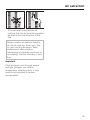
Operating and Installation Instructions
Ventilation System
To prevent accidents and machine damage, read these instructions
before installation or use.
en - US, CA
M.-Nr. 09 824 260
Installation Instructions
Read these instructions and the "Important Safety Instructions" before installing
this ventilation system.
The installation steps are described in the enclosed "Installation Diagram".
Leave these instructions with the appliance for the consumer/user.
Information is subject to change. Please refer to our website to obtain the most
current product specification, technical & warranty information.
17
Caring for the environment
Disposal of packing material
Disposal of an old appliance
The cardboard box and packing
materials protect the appliance during
shipping. They have been designed to
be biodegradable and recyclable.
Please recycle.
Old appliances may contain materials
that can be recycled. Please contact
your local recycling center about the
possibility of recycling these materials.
,DANGER
Ensure that any plastic wrappings,
bags, etc., are disposed of safely
and kept out of the reach of babies
and young children. Danger of
suffocation!
18
Before discarding an old appliance,
disconnect it from the electrical
supply and cut off the power cord to
prevent it from becoming a hazard.
Appliance dimensions
19
Appliance dimensions
20
Appliance dimensions
a The hood with exhaust collar is only used in air extraction mode with an internal
or external blower.
b Installation area; Wall/ceiling area respectively for vent hole and outlet
installation. For recirculation mode only the outlet installation is required.
21
Appliance dimensions
a The hood with exhaust collar is only used in air extraction mode with an internal
or external blower.
b Installation area; Wall/ceiling area respectively for vent hole and outlet
installation. For recirculation mode only the outlet installation is required.
22
Appliance dimensions
a Installation area; Wall/ceiling area respectively for vent hole and outlet
installation.
23
Appliance dimensions
Distance between cooktop and hood (S)
Do not install this exhaust hood over cooktops burning solid fuel.
Observe the cooktop manufacturer's instructions when determining the
distance between cooktop and lower edge of the hood.
Unless the instructions require a greater distance, the adjacent minimum safety
distances apply for Miele cooktops.
– If several gas surfaces are installed under the hood, the total output must be
considered when determining the minimum safety distance.
– Be sure to follow the minimum safety distances given by the gas cooktop
manufacturer to easily flammable materials e.g. upper cabinets.
– If local building codes require a greater safety distance, follow their requirement.
– If there is more than one appliance beneath the hood and they have different
minimum safety distances always select the greater distance.
See "Important Safety Instructions" for further information.
– To ensure free access to work under the ventilation hood, a distance of a
minimum of 26" (660 mm) above the electric cooktop is also recommended.
– Take the user's body height into consideration when selecting the installation
height. Adequate work space at the cooktop and optimal operation of the
ventilation system should be ensured.
– However, the greater the distance from the cooktop, the less effectively cooking
odors are drawn in.
24
Appliance dimensions
Distance between cooktop and hood (S)
Miele Range hood
Internal / External blowers
DAR 1120,
DAR 1220
(30")
DRIB/DREB
XL
(700 cfm)
DAR 1130, DAR 1230
(36")
DRIB/DREB
XL
(700 cfm)
DRIB/DREB
XXL
(1100 cfm)
Miele Electric Cooktops
24" (610 mm)
Miele Electric Barbeques and
Fryers
26" (660 mm)
Miele Multiburner Gas cooktops
< 43,000 BTU/hr (12.6 KW)
and no burner >18,800 BTU/hr
(5.5 KW)
26" (660 mm)
Miele Multiburner Gas cooktops >
43,000 BTU/hr (12.6 KW)
< 92,200 BTU/hr (27 KW)
and no burner >>18,800 BTU/hr
(5.5 KW)
30" (760 mm)
Miele Multiburner Gas cooktops >
92,200 BTU/hr (27 KW)
< 109,200 BTU/hr (32 KW)
and no burner >>18,800 BTU/hr
(5.5 KW)
Miele Multiburner Gas cooktops >
109,200 BTU/hr (32 KW)
< 136,500 BTU/hr (40 KW)
and no burner >>18,800 BTU/hr
(5.5 KW)
not
possible
36" (910 mm)
not
possible
DAR 1150,
DAR 1250
(48")
DRIB/DREB
XXL
(1100 cfm)
30" (760 mm)
36" (910 mm)
Miele Multiburner Gas cooktops >
136,500 BTU/hr (40 KW)
not possible
Miele Multiburner Gas cooktops
one of the burners>>18,800 BTU/hr
(5.5 KW)
not possible
Miele Single burner (Wok)
< 20,500 BTU/hr (6 KW)
26" (660 mm)
Miele Single burner (Wok)>>
20,500 BTU/hr (6 KW)
< 27,600 BTU/hr (8.1 KW)
30" (760 mm)
Miele Single burner (Wok)>>
27,600 BTU/hr (8.1 KW)
not possible
25
Plywood backing
The majority of the weight of the
installed ventilation system will be
supported by the retaining plate. It
must be firmly attached to the stud
framing behind the drywall. If studs
are not available in the required
locations, a plywood backing (min.
½" (13 mm) thick) spanning at least
two studs must be installed. Failure
to adequately support the weight as
stated may result in the ventilation
system falling off the wall, causing
personal injury and property
damage.
(If plywood backing is not needed,
proceed to the included "Installation
diagram".)
To install a plywood backing
^ Determine and mark the location for
the canopy as outlined in "Appliance
dimensions".
^ Make a cutting line 3" (76 mm) above
and 3" (76 mm) below the outline of
the retaining plate.
26
^ Find the studs to the left and right of
the mounting location by tapping the
wall or using a stud finder.
^ Mark a vertical cutting line along the
center of each stud.
,CAUTION
When cutting or drilling into the wall
or ceiling, do not damage electrical
wiring and other hidden utilities.
^ Remove the drywall between the
cutting lines and replace it with
plywood of a matching thickness
(min. ½" (13 mm) thick). Tape the
joints and refinish the wall.
^ Proceed to the enclosed "Installation
diagram" to complete the installation.
Installation
Before installation read the
information in the "Dimensions" and
"Important Safety Instruction"
chapters.
Under certain conditions, there is a
danger of poisonous fumes by when
the ventilation system and a furnace
drawing interior air run at the same
time.
Installation instructions
The individual installation steps are
described in the included Installation
diagram.
Protective film
(stainless steel units)
The casing is covered with a protective
film to prevent scratching during transport.
Please peel off the film before installing
the casing parts. It can be removed
without tools.
27
Air extraction
,WARNING
Danger of toxic fumes.
Gas cooking appliances release
carbon monoxide that can be
harmful or fatal if inhaled.
To reduce the risk of fire and to
properly exhaust air, the exhaust
gases extracted by the hood
should be vented outside of the
building only.
Do not vent exhaust air into
spaces within walls or ceilings or
in attics, crawl spaces or garages.
To reduce the risk of fire, only use
metal ductwork.
Exhaust ducting and connections
Use smooth or flexible pipework made
from approved non-flammable
materials for exhaust ducting.
To achieve the most efficient air
extraction and quietest noise levels,
consider the following:
– The diameter of the ductwork should
not be less than 8" (203 mm) with
DRIB/DREB XL and 10" (254 mm)
with DRIB/DREB XXL.
– If flat ducting is used, the cross
section must not be smaller than the
cross section of the ventilation
exhaust.
– The ducting should be as short and
straight as possible.
– Use ductwork with a wide radius.
Please read and follow the
"IMPORTANT SAFETY
INSTRUCTIONS" to reduce the risk of
personal injury. Follow all local building
codes when installing the hood.
– The exhaust duct must not be bent
or compressed.
– Make sure all connections are
secure.
– Where the ductwork is horizontal, it
must slope away from the hood at
least 1/8" per foot (1 cm per meter) to
prevent condensation dripping into
the appliance.
28
Air extraction
– If the exhaust is ducted into an
inactive flue, the air must be expelled
parallel to the flow direction of the
flue.
Never connect an exhaust hood to
an active chimney, dryer vent, flue,
or room venting ductwork. Seek
professional advice before
connecting an exhaust hood vent to
an existing, inactive chimney or vent
flue.
Important
If the ductwork runs through rooms,
ceilings, garages, etc. where
temperature variations exist, it may
need to be insulated to reduce
condensation.
29
Electrical connection
,WARNING
TO REDUCE THE RISK OF
FIRE, ELECTRIC SHOCK, OR
INJURY TO PERSONS,
OBSERVE THE FOLLOWING:
All electrical work should be
performed by a qualified electrician
in strict accordance with national
regulations (for USA: ANSI-NFPA
70) and local safety regulations.
Installation, repairs and other work
by unqualified persons could be
dangerous.
Ensure that power to the appliance
is OFF while installation or repair
work is performed.
^ Verify that the voltage, load and
circuit rating information found on the
data plate (located behind the baffle
filters), match the household
electrical supply before installing the
hood.
^ Use only with ventilation hood
cord-connection kits that have been
investigated and found acceptable
for use with this model hood.
If there is any question concerning the
electrical connection of this appliance
to your power supply, please consult a
licensed electrician or call Miele’s
Technical Service Department.
,WARNING:
THIS APPLIANCE MUST BE
GROUNDED
30
Grounding Instructions
This appliance must be grounded. In
the event of an electrical short circuit,
grounding reduces the risk of electric
shock by providing a path of least
resistance. This appliance is equipped
with a cord having a grounding wire
with a grounding plug. The plug must
be plugged into an outlet that is
properly installed and grounded.
WARNING - Improper grounding can
result in a risk of electric shock.
If there is any doubt, have the electrical
system of the house checked by a
qualified electrician.
Do not use an extension cord. If the
power supply cord is too short, have a
qualified electrician install an outlet
near the appliance.
Important
The hood comes equipped with a
power cord with a NEMA 5-15 molded
plug for connection to a 120 VAC,
60 Hz, 15 A power outlet.
Technical data
Total connected load
Weight
DAR 1120, DAR 1220
with DRIB XL or DREB XL . . . . . . 619 W
DAR 1120
with DRIB XL . . . . . . . 59.6 lbs (27.1 kg)
DAR 1130, DAR 1230
with DRIB XL or DREB XL . . . . . . 621 W
DAR 1220
with DRIB XL . . . . . . . 83.8 lbs (38.1 kg)
DAR 1130, DAR 1230
with DRIB XXL or DREB XXL . . . . 806 W
DAR 1130
with DRIB XL . . . . . . . 66.2 lbs (30.1 kg)
DAR 1130
with DRIB XXL . . . . . . 66.7 lbs (30.3 kg)
DAR 1150, DAR 1250
with DRIB XXL or DREB XXL . . . . 808 W
Overhead lights
DAR 1120, DAR 1220 . . . . . . . . 2 x 2 W
DAR 1130, DAR 1230 . . . . . . . . 3 x 2 W
DAR 1150, DAR 1250 . . . . . . . . 4 x 2 W
Power supply voltage . . . . . . . . . 120 V
Frequency . . . . . . . . . . . . . . . . . . 60 Hz
DAR 1230
with DRIB XL. . . . . . . . . 97 lbs (44.1 kg)
DAR 1230
with DRIB XXL . . . . . . 97.5 lbs (44.3 kg)
DAR 1150
with DRIB XXL . . . . . . 79.9 lbs (36.3 kg)
DAR 1250
with DRIB XXL . . . . . 130.5 lbs (59.3 kg)
Circuit rating. . . . . . . . . . . . . . . . . . 15 A
31
32
33
34
35
DAR 1120, 1130, 1150
DAR 1220, 1230, 1250
en - US, CA
M.-Nr. 09 824 260 / 01