1
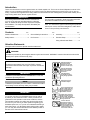
SHINDAIWA GRASS TRIMMER TO BLADE CONVERSION INSTRUCTIONS Model 80559 For Trimmer T230, T231, T2500, T2510, 65001 WARNING! Minimize the risk of injury to yourself and others! Read the Owner's/Operator's manual originally supplied with the unit that is being upgraded and familiarize yourself with the contents. Always wear eye and hearing protection when operating your unit. X7502802200 08/10 Introduction These are instructions to convert a grass trimmer to a blade capable unit. This is not an Owner's/Operator's manual. Information on how to operate and maintain the unit can be found in the Owner's/Operator's manual for the unit you are converting. Note this kit is supplied with a cutting attachment shield that has been redesigned to provide better visibility and a larger cutting swath when used as a grass trimmer. IMPORTANT! IMPORTANT! If the cutting attachment shield has been removed from your unit or the unit was manufactured prior to October 2001, an additional clamp kit will be required to complete this installation. The clamp kit required is Shindaiwa part number 80292. Contents The information contained in these instructions describes the product available at the time of publication. Echo, Inc. reserves the right to make changes to products without prior notice, and without obligation to make alterations to units previously manufactured. PAGE PAGE PAGE Attention Statements.........................2 General Safety Instructions...............3 Assembly...........................................4 Safety Labels.....................................3 Kit Contents.......................................3 Shoulder Strap..................................8 Using a Brushcutter Blade.................8 Attention Statements Throughout this manual are special “attention statements”. WARNING! A statement preceded by the triangular attention symbol and the word “WARNING” contains information that should be acted upon to prevent serious bodily injury. CAUTION! A statement preceded by the word “CAUTION” contains information that should be acted upon to prevent mechanical damage. IMPORTANT! A statement preceded by the word “IMPORTANT” is one that possesses special significance. NOTE: Read and follow this operators manual. Failure to do so could result in serious injury. Wear eye and hearing protection at all times during the operation of this unit. Keep bystanders at least 50 feet (15 m) away during operation. Beware of thrown or ricocheted objects. A statement preceded by the word “NOTE” contains information that is handy to know and may make your job easier. IMPORTANT! The instructions described in this manual are intended to help you get the most from your Shindaiwa power tool as well as to protect you and others from harm. These procedures are guidelines for safe operation under most conditions, and are not intended to replace any safety rules and/or laws that may be in force in your area. If you have questions regarding your Shindaiwa power tool, or if you do not understand something in these instructions, your Shindaiwa dealer will be glad to assist you. You may also contact Shindaiwa at the address printed on the back of this instructional manual. 2 Do not operate this unit with a blade unless the unit is equipped with a Shindaiwa-approved handlebar or barrier. Always wear a harness when operating this unit with a blade. A harness is also recommended when using trimmer line. If unit is used as a brushcutter, beware of blade thrust. A jammed blade can cause the unit to jerk suddenly and may cause the operator to lose control of the unit. Safety Labels BCC03 IMPORTANT! Safety and Operation Information Labels: Make sure all information labels are undamaged and readable. Immediately replace damaged or missing information labels. A new label is provided in this kit and additional labels are available from your local authorized Shindaiwa dealer. Prior to installing the new label, Remove old label and clean the outer tube with rubbing alcohol or similar cleaner. General Safety Instructions WARNING! ■■When operating with a blade, make sure the handle is positioned to provide you with maximum protection from contacting the blade. Always make sure the handlebar is installed in accordance with the manufacturers instruction. ■■ALWAYS Shut off the engine immediately if a blade binds in a cut. Push the branch or tree to ease the bind and free the blade. ■■Beware of a coasting blade when brushcutting or edging. A coasting blade can injure while it continues to spin after the throttle trigger is released or after the engine is stopped. ■■NEVER use a cracked or warped blade: If a properly installed blade vibrates, replace it with a new one and re-check. Kit Contents 3 6 11 2 # Description Qty 1 2 3 4 5 6 7 Warning Label Debris Shield Debris Shield Extension Upper Clamp Spacer Shoulder Strap Hanger M5 x 12 mm Socket Head Cap Screw M5 Nut M5 x 35 mm SPW Bolt Barrier Bar M5 Nut Bolt Guard M7 x 22 mm SW Bolt Holder (A) Holder (B) Safety Clip Collar M5 x 34mm Bolt Assembly Tool (s) 1 1 1 1 2 1 1 8 10 5 12 19 1 4 9 7 8 14 15 17 16 13 18 9 10 11 12 13 14 15 16 17 18 19 20 1 1 4 1 4 1 1 1 1 1 1 4 3 Assembly Removing the Old Cutting Attachment Shield Remove the Existing Cutting Attachment Shield. Socket-Head Cap Screws 1. Remove the four socket-head cap screws, bracket and two shims. See Figure 1. 2. Remove the retaining nut, washer and gearcase clamp screw. If possible, do not disturb the D-washer. 3. Remove the cutting attachment shield from the gearcase. Shim Bracket Gearcase Housing Shim Outer Tube D-washer CAUTION! The D-Washer is a spacer that prevents overtightening and must remain in place to prevent possible damage to the gearcase clamp. Gearcase Clamp Screw Cutting Attachment Shield Washer Retaining Nut TSU05 Figure 1 Barrier Bar and Hanger Assembly Socket-head Capscrews Handle Throttle Assembly 1. Remove the four socket-head cap screws on the handle and remove the handle and mounting bracket. 2. Unscrew gearcase housing locating screw, and slide gearcase off of outer tube. 3. Position the hanger on the outer tube between the handle and throttle assembly and secure the hanger with the nut and bolt as shown in Figure 2. Nut 4. Slide gear case on to outer tube and align locating holes. 5. Thread locating screw into locating hole, and tighten securely. Outer Tube Bolt Hanger BCC07 Handle Positioning Label Barrier Bar Figure 2 4 Nuts 6. Position the handle on the outer tube forward of Handle Positioning Label as shown in Figure 2. 7. Install the barrier bar with the socket-head cap screws and nuts. Tighten the screws finger-tight ONLY at this time. 8. Locate the handle in the best position for operator comfort (usually about 10 inches ahead of the throttle housing). 9. Secure the handle by alternately tightening the four socket-head screws in a diagonal or “criss-cross” fashion. New Cutting Attachment Shield Assemble the Cutting Attachment Shield to the Outer Tube. 1. Attach cutting attachment shield mounting plate to gear case housing using clamp screw, washer, and retaining nut, and tighten finger tight. Socket-head Cap Screws Upper Clamp 2. Make sure that the D-washer is installed in the gear case clamp, flat side facing outer tube. 3. Insert the cutting attachment shield between the outer tube and the cutting attachment mounting plate. See Figure 3. Shim Sub-shield Cutting Attachment Shield 4. Fit the two shims and the bracket over the outer tube and install the four socket-head cap screws finger tight. See Figure 3. 5. Tighten the gearcase clamp screw, then install the washer and retaining nut and tighten securely. Cutting Attachment Shield Shim Nut Cutting Attachment Shield Mounting Plate Figure 3 CAUTION! Make sure the clamp screw and retaining nut are securely tightened before tightening the four socket head screws. 6. Tighten the four socket-head cap screws to secure the cutting attachment shield. Sub-Shield. (when trimmer head is in use) 1. Attach the shield extension to the cutting attachment shield. WARNING! WARNING! NEVER operate the unit without the cutting attachment shield installed and tightly secured! WARNING! NEVER use this machine without sub-shield when using a trimmer head. CAUTION! Make sure the sub-guard is completely hooked at the hook receiver. A cutting attachment shield or other protective device is no guarantee of protection against ricochet. YOU MUST ALWAYS GUARD AGAINST FLYING DEBRIS! 5 Install Blade 1. Turn the unit over so that the gearcase output shaft faces UP. 2. Align the hole in the holder with the notch in the gearcase flange, and then temporarily lock the output shaft by inserting a hex wrench through both holes. Hex Wrench 3. While holding the hex wrench turn the trimmer head clockwise to remove. Remove trimmer head mounting bolt. Remove the hex wrench. See figure 4. Figure 4 26107 4. Remove and discard the holder and collar. See Figure 5. Output Shaft Holder 5. Install the new collar. See Figure 5. Collar Figure 5 Assembly: Blade T261X Assembly: Blade T261X 6. Install Holder Blade. (A) and safety clip. See Figure 6. Mount the Cutting Mount the Cutting Blade. Shaft Bolt Shaft Bolt Slide the safety clip off-center Slide the safety clip off-center Turn the T61X upside down so the Turn the T61X upside downUP soand the gearcase output shaft is facing Bolt Guard gearcase output shaft is facing UP remove the shaft bolt, bolt guard and and Bolt Guard 7. Next, slide the safety clip off-center. See Figure 6. remove the shaft bolt, bolt guard and holder B from the gearcase shaft. Output Holder B holder B from the gearcase shaft. Output Shaft Holder B 1. Align the hole in blade holder A with Shaft 1. Align the hole in blade holder A with the matching hole in the gearcase Gear Shaft Holder (A) the matching hole in the gearcase Gear Shaft flange and then temporarily lock the Safety flange andby then temporarily the Safety Clip output shaft inserting a hex lock wrench Safety Clip Safety Clip output shaft by inserting a hex wrench through both holes. See Figure 1. Clip Holder A through both holes. See Figure 1. 6 13 23110 Figure Holder A Figure . Slide the safety clip off-center. See 23110 Figure 13 . Slide13. the safety clip off-center. See Figure 8.Figure Fit the13. blade over the safety clip and then center it over the flange 3. Fit the over safety clip and on blade Holder (A).the See Figure 7. 3. Fitcenter the blade over the safetyonclip and then it over the flange holder then center it over the flange on holder A. See Figure 14. 26109 A. See Figure 14. NOTE: 26109 CAUTION! When installing certain blades, it may be necessary to temporarily Center the Safety Slip the Saw Blade In CAUTION! Center Slip the Saw Blade In Clipthe Safety Place remove safety Install the the blade so itsclip. printed surHex Wrench Clip Place Install the blade its printed surHex Wrench face is visible to thesooperator when face is visible to the operator when the brushcutter is in the normal Figure 14 Figure 12 theCAUTION! brushcutter 14 Figure 12 FigureFigure 7 operating position.is in the normal operating Install theposition. blade so its printed surface is visible to the operator when the brushcutter is in the normal operating position. WARNING! WARNING! The blade must fit flat The blade must flange. fit flat against the holder Output against the holder The blade mounting hole must flange. be Output Shaft Blade The blade mounting hole must be Shaft centered over the raised boss on Blade centered blade holderover A. the raised boss on 6 blade holder A. 26111 26111 26112 26112 NOTE: NOTE: WARNING! Install Holder (B) The blade must fit flat against the holder flange. The blade mounting hole must be centered over the raised boss on blade Holder (A). Saw Blade 9. Lock the blade in place by centering the safety clip on the output shaft. See Figure 8. Bolt Guard Tighten the Assembly BLADE NOT SHOWN FOR CLARITY! WARNING! Never operate a unit with a blade without the safety clip in place! WARNING! A standard grass trimmer unit with loop handle should NEVER be operated with blade-type attachments. For blade use, the trimmer must be fitted with a bicycle-type handlebar or barrier bar that is located in front of the operator to reduce the risk of the operator coming in contact with the cutting attachment. (Per ANSI B175.3). When using a blade, the unit must be equipped with a harness or strap. Spark Plug Wrench Hex Wrench Figure 8 Install Holder (A) WARNING! Holder (B) must fit flush against the blade and the splines engaged to the output shaft. 10.Install blade Holder (B) on the output shaft. See Figure 8. The recess in the holder must completely cover the safety clip, and must fit tightly against the blade. 11.Align the hole in blade Holder (A) with the notch in the gearcase flange, and then lock the output shaft by inserting a hex wrench through both holes. 12.Install the bolt guard and then the blade retaining bolt. Using the spark plug wrench, tighten the bolt firmly in a counter-clockwise direction. 13.Remove the hex wrench. The unit should now be completely assembled and ready for use with a blade. IMPORTANT! Units with adjustable carburetors must be readjusted for blade use, otherwise serious engine damage can occur. WARNING! Cutting attachment must not move at idle, otherwise serious injury can result. See “Idle speed adjustment” section in the unit Operator’s Manual. 7 Shoulder Strap Adjust the shoulder strap so the shoulder pad rests comfortably on the off-side shoulder and the cutting path of the cutting attachment is parallel to the ground. Tighten hanger screw. WARNING! Always wear a shoulder strap when operating this unit with a blade. A shoulder strap is also recommended when using trimmer line. NOTE: Using a shoulder strap with a brush-cutter allows you to maintain proper control of the unit and reduces fatigue during extended operation. NOTE: Although a shoulder strap accessory is not required for use with a grass trimmer, a shoulder strap can increase operator comfort during extended periods of operation. Using A Brushcutter Blade WARNING! Before working with a blade-equipped unit, always inspect and clean the area of objects that could interfere with or damage the blade. Never use a blade near sidewalks, fence posts, buildings or other objects that could cause injury or damage. Never use a blade for purposes other than those for which it was designed. Whenever you strike a hard object with a blade, always stop the brushcutter and carefully inspect the blade for damage. NEVER OPERATE THE UNIT WITH A DAMAGED BLADE! A blade-equipped unit must be equipped with a bicycle-type handlebar or barrier as well as a harness or strap. Always make sure the cutting attachment shield is properly installed before operating the unit. Blade Thrust ‘Blade thrust’ is a sudden sideways or backward motion of the brushcutter. Such motion may occur when the blade jams or catches on an object such as a sapling tree or tree stump. BE CONSTANTLY ALERT FOR BLADE THRUST AND GUARD AGAINST ITS EFFECTS! Eleven O’Clock Barrier Bar A brushcutter’s barrier bar helps prevent the operator from moving forward, or the unit moving rearward, thus preventing inadvertent bodily contact with the blade. ALWAYS KEEP THE BARRIER BAR SECURELY IN PLACE ON THE UNIT! Shoulder Strap or Harness A shoulder strap or harness provides additional protection against blade thrust. In addition, a shoulder strap or harness gives significant support and comfort to help ensure safe and efficient operation. When operating a unit equipped with a blade, make sure both the handle/ barrier bar and shoulder strap or harness are adjusted to the size of the operator using the unit. The blade rotates counter-clockwise. For best performance and to minimize being struck by debris, move the blade from right to left while advancing on your work. Position the blade so cuts are made between the blade’s 7 o’clock and 11 o’clock positions (as viewed from above). DO NOT cut between the 11 o’clock and 5 o’clock positions (shaded area). 8 DO NOT C UT Blade Rotation OK To Cut Seven O’Clock Five O’Clock BCC17 NOTES 9 NOTES 10 NOTES 11 Consumer Product Support If you require assistance or have questions concerning the application, operation or maintenance of this product you may call the Shindaiwa Consumer Product Support Department at 1-877-986-7783 from 8:30 am to 4:30 pm (Central Standard Time) Monday through Friday. Before calling, please know the model and serial number of your unit. ECHO Incorporated. 400 Oakwood Road Lake Zurich, IL 60047-1564 U.S.A. Telephone: 1-877-986-7783 Fax: 1-847-540-8416 www.shindaiwa.com Copyright© 2010 By Echo, Incorporated All Rights Reserved. Yamabiko Corporation 7-2 Suehirocho 1-Chome, Ohme, Tokyo, 198-8760, Japan Phone: 81-428-32-6118 Fax: 81-428-32-6145