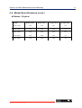
1
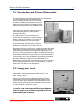
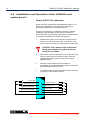
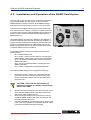
Ref: 610MANUAL
Rev 4 Issued:Feb 98
Installation and
Operation Manual
SOLA 610
0.7, 1, 1.5, 2 & 3kVA
50/60 Hz Single Phase
Uninterruptible Power System
Save these instructions!
This manual contains important instructions that should
be followed during installation and maintenance of the UPS.
Conserver ces instructions!
Cette notice contient des instructions importantes
concernant la securite!
A
The Answer in Power Protection
bp
Company
SAVE THESE INSTRUCTIONS
THIS MANUAL CONTAINS IMPORTANT INSTRUCTIONS FOR YOUR UPS
WARNING!
This unit has an internal battery and is capable of
generating dangerous voltages. Do not open the unit by
removing the outer case. Please read SAFETY
WARNINGS on Pages v and vi.
The unit can generate power even when disconnected
from the utility supply. Ensure you read this manual
carefully and are aware of the correct operating
parameters.
How to talk to us
If you have any problem, a question, or require any information on SOLA’s extensive
range of UPS and power protection equipment, this is where to contact us.
SOLA Australia Ltd
13 Healey Road
Dandenong, Victoria 3175
Australia
Telephone:
Fax:
Service:
61-3-9706 5022
61-3-9794 9150
1800 034 401 Free Call (callers outside Melbourne)
9768 3105
(Melbourne metro callers)
SOLA Home Page Address .... www.solaaust.com.au
SOLA Australia Ltd
Customer Service Offices
Adelaide
( 08-8347 3622
Fax: 08-8445 6328
Brisbane
( 07-3891 1211
Fax: 07-3891 2492
Melbourne
( 03-9706 5662
Fax: 03-9794 9150
Perth
( 08-9478 3511
Fax: 08-9479 4577
Sydney
( 02-9949 6000
Fax: 02-9907 9802
The Answer in Power Protection
SOLA 610 UPS General Information
i
1.1 Table of Contents
Page Number
1.
General Information
1.1
1.2
1.3
1.4
1.5
2.
1
1
2
2
2
3
4
4
5
Switching on the UPS ...............................................................
When the power fails ................................................................
When the power returns ............................................................
Front panel indicators ...............................................................
6
6
7
7
Optional Features
4.1
4.2
4.3
4.4
4.5
5.
Introduction and product description ..........................................
Sizing the load ..........................................................................
Types of loads ..........................................................................
Laser Printers and your UPS .....................................................
Unpacking your UPS ................................................................
UPS locations ...........................................................................
Recharging the UPS battery ......................................................
External Battery connection ......................................................
Setting up the UPS monitoring from your computer ...................
UPS Operation
3.1
3.2
3.3
3.4
4.
i
ii
iii
iv
v
Installation
2.1
2.2
2.3
2.4
2.5
2.6
2.7
2.8
2.9
3.
Table of Contents .....................................................................
Notice to UPS owners ...............................................................
Preface .....................................................................................
FCC & Dept. of Communications Notice ....................................
Safety Notice and Warnings ......................................................
Internal Battery Data .................................................................
External Battery Options ...........................................................
Installing and Operating CheckUPS II® .....................................
Installation and Operation of the AS400® card option ................
Installation and operation of the SNMP Card option ...................
8
9
11
11
13
Maintenance and Warranty
5.1
5.2
5.3
5.4
5.5
5.6
Storage ....................................................................................
Maintenance and Cleaning ........................................................
Trouble shooting .......................................................................
Model specifications .................................................................
Warranty ..................................................................................
Service instruction and service locations ...................................
The Answer in Power Protection
14
14
15
16
18
19
SOLA 610 UPS General Information
ii
1.2 Notice to UPS Owners
Thank you for choosing a SOLA product, your answer in power
protection. Over many years SOLA has built a reputation by
designing and manufacturing top quality, reliable power quality
products. Your SOLA unit is designed for trouble-free operation
in a normal commercial environment.
In the unlikely event that your SOLA does need repair, please
refer to Section 5.6 of this manual. Should you wish to upgrade
the service guarantee to the premier FASTFIX exchange
service, or extend your warranty beyond the initial two years,
please contact your local SOLA office.
We encourage you to read this manual carefully in order to get
full benefit from the features built into your SOLA product. It is
recommended that you register your purchase by completing
the warranty registration card at the back of this manual..
WARNING!
This unit has an internal battery
and is capable of generating
dangerous voltages. Do not open
the unit by removing the outer
case. Please read the SAFETY
WARNINGS on pages v and vi.
The Answer in Power Protection
SOLA 610 UPS General Information
iii
1.3 Preface
SOLA makes no warranty of any kind with regard to this
document, including, but not limited to, the implied warranties of
merchantability and fitness for a particular purpose. SOLA shall
not be liable for errors contained herein or for incidental or
consequential damages in connection with the furnishing,
performance, or use of this material.
This document contains proprietary information which is
protected by copyright. All rights are reserved. No part of this
document may be photographed, reproduced or translated to
another language without the prior written consent of SOLA.
This manual contains technical information about the following
SOLA UPS systems@
Input/Output
Voltage
Frequency
(autoselecting)
Socket type
S610-0700-A000-00
240V
50/60 Hz
A ustralian
0610-1000A
S610-1000-A000-00
240V
50/60 Hz
A ustralian
1500
0610-1500A
S610-1500-A000-00
240V
50/60 Hz
A ustralian
2000
0610-2000A
S610-2000-A000-00
240V
50/60 Hz
A ustralian
3000
0610-3000A
S610-3000-A000-00
240V
50/60 Hz
A ustralian
Rating VA
Model No.
Part No.
700
0610-0700A
1000
The Answer in Power Protection
SOLA 610 UPS General Information
iv
1.4 FCC & Department of Communications Notice
FCC NOTICE
This equipment generates and uses radio frequency energy; and, if installed in a residential
environment, may cause interference to radio and television reception. It has been type tested
and found to comply with the limits for a Class A/B* digital device, pursuant to part 15 of the
FCC rules. These limits provide reasonable protection against harmful interference when the
equipment is operated in a commercial environment. This equipment generates, uses and can
radiate radio frequency energy and, if not installed and used in accordance with the instruction
manual, may cause harmful interference to radio communications. Should the unit be installed
in a residential environment, it is the user's responsibility to remedy potential television and/or
radio interference. The following FCC booklet may be helpful in resolving interference:
How to Identify and Resolve Radio-TV Interference Problems (Stock Number 004-0000345-4)
This booklet is available from the U.S. Government Printing Office, Washington, DC 20402.
DEPARTMENT OF COMMUNICATIONS NOTICE
This digital apparatus does not exceed the Class A/B* limits for radio noise emissions from
digital apparatus as set out in the Radio Interference Regulations of the Canadian Department
of Communication.
AVIS DU MINISTERE DES COMMUNICATIONS
Les emissions de bruit radioelectrique produites par ce dispositif numerique respectant les
normes de Classe A/B* afferentes aux dispositifs numeriques enoncees dans le Reglement
relatif au brouiliage radioelectrique du Ministere Canadien des Communications.
The products meet the above as follows:
1.
2.
3.
FCC Part 15 Class A for 700VA, 1000VA, 2000VA, 3000VA, 120V version.
EN50082-1/EN55022 Class B for 700VA, 1000VA, 2000VA, 3000VA 230V version.
Requirements for fixation of C-Tick 240V logo in Australia.
The Answer in Power Protection
SOLA 610 UPS General Information
v
1.5 Safety Notice and Warnings
Important! Please read this before installing your UPS.
Warnings, Cautions and Notes appear throughout this manual. Please familiarise yourself with them
as they are essential for your safety and will enable you to maximise longevity of your UPS.
WARNING
Denotes a procedure or practice, which, if not performed correctly or adhered to,
may result in personal injury. Do not proceed beyond a Warning sign until the
indicated conditions are fully understood and met.
CAUTION
Denotes a procedure or practice, which, if not performed correctly or adhered to,
may result in damage to equipment. Do not proceed beyond a Caution sign until
the indicated conditions are fully understood and met.
!
Note
Denotes an essential procedure or practice.
?
Safety Warnings
1.
SERIOUS INJURY CAN OCCUR IF THE UNIT ENCLOSURE IS OPENED BY
UNQUALIFIED PERSONNEL. THERE ARE NO USER-SERVICEABLE PARTS
INSIDE THE UPS.
2.
This unit is capable of supplying AC voltage even if there is no input present. Although
the System On/Off Switch on the front of the UPS is protected from accidental
actuation, be careful the unit does not become unintentionally enabled.
3.
The SOLA 610 is not authorised for use as a critical component in life support devices
without the express written approval of the President of Best Power, as used herein:
a.
b.
Life support devices are devices or systems which sustain life, and whose failure
to perform can be reasonably expected to result in a significant injury to the
user.
A critical component is any component of a life support device or system whose
failure to perform can be reasonably expected to cause the failure of life support
or the system, or to affect its safety or effectiveness.
4.
The SOLA 610 is a physically small package. Do not install the unit in a high traffic
area where people could trip on the unit, or its cables or cords.
5.
Do not place objects or stack other equipment on top of the unit.
The Answer in Power Protection
SOLA 610 UPS General Information
vi
1.5 Safety Notices and Warnings (cont.)
Safety Warnings (cont.)
6.
The SOLA 610 is intended for indoor use only.
7.
Do not install the unit next to open windows where uncontrolled environmental
conditions could affect the unit.
8.
Avoid plugging the unit into a wall outlet controlled by a switch. If the outlet is
controlled by a switch, cover or protect the switch from being accidentally turned
off. The wall switch will not turn off the UPS; instead the UPS may draw energy
from its battery and continue to supply output voltage. This may result in a loss
of backup protection until the battery is recharged.
9.
A BATTERY CAN PRESENT A RISK OF ELECTRICAL SHOCK AND/OR
BURN FROM HIGH SHORT-CIRCUIT CURRENT. OBSERVE PROPER
PRECAUTIONS.
UNE BATTERIE PEUT PRÉSENTER UN RISQUE DE CHOC ÉLECTRIQUE,
DE BRÛLURE PAR TRANSFER D'ÉNERGIE. SUIVRE LES PRÉCAUTIONS
QUI S'IMPOSENT.
10.
PROPER DISPOSAL OF BATTERIES IS REQUIRED. REFER TO YOUR
LOCAL CODES FOR DISPOSAL REQUIREMENTS.
L'ÉLIMINATION DES BATTERIES EST RÈGLEMENTÉE. CONSULTER LES
CODE LOCAUX À CET EFFET.
11.
The input cord is the main disconnect.
Der Netzkabel is der Netztrennung.
12.
The unit must be installed near the equipment to be powered and the socketoutlet must be easily accessible.
Die Steckdose soll nahe des Geraetes eingebaut werden und leichter Zugang
haben.
13.
No user-serviceable parts inside.
Kein gebrauche Zugang noetig.
14.
Battery replacement by qualified service personnel only.
Batterieaustauch nur vom qualifizierten Wartungspersonal durchgefuehrt
werden.
The Answer in Power Protection
SOLA 610 UPS Installation
2.1 Introduction and Product Description
An Uninterruptible Power System is designed to connect between
your utility supply wall outlet or distribution board
and your critical load. Its function is to continually
monitor the availability and quality of the electrical
supply and to recreate the mains voltage to remain
within the UPS specifications, as detailed for each
model.
Your SOLA 610 is an advanced true on-line sine
wave UPS with bypass line, utilising double
conversion technology.
The utility power enters the UPS where it is
rectified to a DC voltage which will float charge the
battery as well as run the DC to AC inverter. The
inverter generates the true sine wave output,
recreating the utility supply voltage. A bypass path
is provided through a transfer switch, should the
UPS become overloaded or an inverter fault occur.
Because the UPS is an on-line design, conditioned power is provided
continuously to your load. During an electrical power failure, the unit
employs its internal maintenance free battery to supply continuous
power for as long as the battery is capable. The UPS autonomy after
a power failure will depend on (a) the size of the UPS and the load of
your equipment (b) the size of the battery used (either the standard
internal battery or external battery pack options), and (c) the state of
the battery and battery charge when the power failure occurs.
Batteries have a finite life that can be affected by excessive use and/
or high ambient temperatures. Under normal operation, you should
expect a 3-5 year life from your UPS battery.
2.2 Sizing your Load
Electrical equipment is often rated in VA (volt-amps). This
represents the rated voltage times the rated current, i.e. 230
Volts x 2 Amp = 460VA.
Check your equipment for the manufacturer’s label. This label
should state the equipment’s desired operating voltage (V) and
current (A) drawn by the equipment. The manufacturer’s label is
usually found on the external rear or underside of the equipment,
or in the handbook or operator’s manual.
M ostcom puters and theirrelated com ponents are rated at
"worstcase",with allofthe expansion slots orbays fully loaded
atlow line voltage,so youractualload is probably lessthan the
load indicated by the m anufacturer.
The Answer in Power Protection
1
SOLA 610 UPS Installation
2
2.3 Types of Loads
The SOLA 610 UPS is designed to power all modern computer
equipment “loads”. The UPS output is specifically designed to
work with switching power supplies found in today's
microprocessor-based equipment.
2.4 Laser Printers and your UPS
SOLA does not recommend protecting laser printers
with this UPS. Laser printers have a heating cycle
which provides adhesion of the toner to the paper.
This heating cycle draws large amounts of electrical
current and will overload your UPS.
Most laser printers are not mission critical and can
therefore be protected with a power conditioner rather
than a UPS. Just be sure that the power conditioner
you purchase can accommodate the high inrush
currents of a laser printer. If your printer is missioncritical and you want to protect it with a UPS, the UPS
must be sized to accommodate the high peak current
surge of the printer.
2.5 Unpacking your UPS
Although the packaging for your SOLA 610 was designed
specifically for this unit and serves it well in protecting the unit
from damage, you should unpack the unit immediately
and check for signs of concealed damage that may
have occurred in transit. Concealed damage is damage
that may not be apparent by the outside appearance of
the packaging.
In case of damage, please notify the delivering carrier
at once to examine the goods, regardless of the
external condition of the boxes. Under U.S. Shipping
Regulations, damage claims must be collected by the
consignee. Once your claim is established, damaged
merchandise may be returned for repair (see Page 33
for Return Policy). Do not return shipping-damaged
merchandise until after your claim has been
established with the carrier.
Do not destroy packing material or boxes until the
carrier's agent has examined them. Save all
packaging materials in case reshipment of the UPS
is required. Any damage sustained in transit when
shipped from the user, especially in an incorrect
container, will not be covered under warranty.
The Answer in Power Protection
SOLA 610 UPS Installation
3
2.6 UPS Locations
Your UPS should be in a controlled environment. A controlled
environment is one that is indoor, temperature-controlled and free of
conductive or semi-conductive contaminants. The SOLA 610 is
intended for indoor use only. There should be adequate ventilation and
the location should be free of dust and fumes. Do not install the unit next
to open windows where uncontrolled environmental conditions could
affect the unit. Do not install the unit in any type of enclosure without first
calling SOLA Technical Support. The unit must have unrestricted air flow.
CAUTION
The environmental specifications shown in Table 1
(below) show the temperature and humidity limits of
the UPS. Do not exceed these limits.
!
ENVIRONMENTAL SPECIFICATIONS
< 1500 m
0oC to 40oC (32oF to 104oF)
1500 - 3000 m
10oC to 35oC
Ambient Storage
All Models:
-15oC to 40oC (5oF to 104oF)
Humidity
All Models:
20% to 95%, non condensing
Altitude
All Models:
8,000 feet (2500M) max.
Ambient Operating
Temperature
Table 1
2.7 Recharging the UPS Battery
To optimise the performance of your UPS we
recommend you ensure the battery is fully charged
before you use the UPS to support your critical load.
To recharge the battery, place the UPS close to a wall
outlet and connect the matching line cord to the UPS
receptacle then plug it into the wall socket. For units
that have hardwired connections, have your electrical
contractor install the UPS wiring.
When power is supplied to the UPS (without operating
any front panel switches), the UPS will go through a
short test sequence, and the cooling fan will start.
On the front panel the line indicator
and the
bypass indicator
will illuminate. At this time there
is power available at the output sockets.
The Answer in Power Protection
SOLA 610 UPS Installation
4
2.7 Recharging the UPS Battery (cont.)
Note
The battery backup feature of the UPS is
not available in this mode. See 3.1
“Switching on the UPS”to enable the
battery backup mode.
?
In this mode, (and normal UPS operating mode) recharging
occurs automatically and will take 10 hours if the batteries are
completely discharged. As UPS units are normally delivered with
charged batteries, providing the UPS has not been in storage for
a long time, it will not take long for the battery to reach full
capacity.
!
CAUTION
IN ALL CONDITIONS, if the UPS is connected
to a live supply, AC POWER IS PRESENT AT
THE UPS RECEPTACLES (or output terminals)
The front panel OFF/ON does NOT control the
delivery of power to the output receptacles.
2.8 External Battery Connection
All units, excluding the 700VA model, can be fitted
with an external battery option to increase the
autonomy when the UPS is operating during a mains
failure. Refer Section 4.1 for selection of external
battery options for your specific UPS.
On the rear of each of the UPS units 1-3kVA capacity
you will find an external battery receptacle. If you
have purchased an external battery option, it will be
supplied with an interconnecting cable to connect into
this receptacle. Use only the matching battery option
for your UPS rating. Using the incorrect battery option
may cause damage to your UPS system. Once
connected, your UPS will maintain the charge in the
external battery providing the utility mains is available.
External Battery Connector
The Answer in Power Protection
SOLA 610 UPS Installation
5
2.9 Setting up the UPS Monitoring from your Computer
Your UPS is fitted with a DB9 communications
connector on the rear panel. From this connector,
you can access opto coupled outputs indicating
mains failure or low battery.
Alternatively, RS232 serial communications is
available. This RS232 provides a proprietary
command sequence for the computer to monitor the
utility and the UPS status and to control the UPS
output. The data format of the RS232 is 2400bps, 8
bit data, 1 stop bit and no parity.
The battery test mode is also available through the RS232
command sequence whilst the UPS is operating and the
power is normal. During the test, the 4 LED’s (line, bypass,
battery and inverter) will light alternatively until the test is
completed.
DB9
Each UPS is supplied with a package of CHECKUPS II®
Advanced UPS communications software. This package
includes the correct interconnection cable for your SOLA 610
UPS. If your computer does not have a DB9 connector on
the serial port, use a standard DB9-DB25 adaptor, available
at most computer accessory stores. The CD-ROM provided
with your UPS includes software for many standard operating
systems and detailed manuals in Adobe Acrobat format. All
utilities required to read and/or print the manuals are included
on the CD-ROM. Refer to section 4.2 & 4.3 for more details
of CheckUPS II® and it’s capabilities.
5 4
3
9 8
TX
2
1
7 6
RX
GND
RS232 Pin Assignment
If you have purchased an AS400® card option, this will be
installed in the communications slot. Be careful to connect
your AS400® interface cable to the correct DB9 connector.
Refer to Section 4.4 for more details of the AS400® card
option.
5 4
9
If you have purchased an SNMP option card, this will be
fitted into the communications slot. Only one (1) card, either
AS40® or SNMP can be fitted into the slot at any one time.
Refer Section 4.5 for more details of the SNMP Card option.
N/O, closes
on Low
Battery
Note 1
The Answer in Power Protection
Remote shutdown when in
battery mode only (i.e. no input
mains power).
Keeping this pin high (+5~+12V)
for 500ms will turn off the UPS
inverter when no input mains
present.
3
8
2
7
1
6
Remote
Shutdown
See Note 1
N/O, closes
on Input
Power failure
N/C, closes
on Input
Power failure
SOLA 610 UPS Operation
6
3.1 Switching on the UPS
Fault
Load Level
and
Runtime
Overload
lights
OFF
Switch
}
ON
Switch
Bypass
Inverter
After completing the installation and battery
recharge, switch on the UPS by pressing the front
panel switch ‘I’. The unit will now commence a
system check sequence before establishing it’s
own inverter power.
Firstly, all the Load Level LEDs will illuminate
together then one by one. Within a few seconds the
Inverter indicator will illuminate, indicating the
inverter has now started and the bypass indicator
will extinguish indicating that the UPS is now in
normal mode.
120V Models only - If during the test sequence the
Line indicator flashes instead of remaining
constant, you have a wiring fault and the line and
neutral conductors are reversed.
If the Line indicator flashes and the battery
indicator illuminates at the same time, your
incoming utility AC source voltage and/or frequency
is out of the UPS specification. The UPS is drawing
energy from the batteries.
Battery
You may now start the critical equipment that you
connected to the UPS. If the load level indicator
exceeds 100% and the audible alarm sounds twice
per second, you have plugged too many items into
the UPS and overloaded it. Remove the non critical
items and check the load level indicators.
Line
3.2 When the Power Fails
Inverter
Battery
When the utility AC source fails, the UPS will
continue to deliver output to the UPS receptacle
from the internal or external batteries and the UPS
inverter. When this occurs, an audible alarm will
sound every 4 seconds and the “line”indicator will
extinguish. The battery indicator will be illuminated
to show that the battery is now being discharged.
The audible alarm can be silenced by pressing the
“I”push button on the front panel. If the battery
continues to discharge until the low battery charge
point is reached, the audible alarm will sound
again. At any time, the audible alarm can be
reactivated by pressing the “on”switch on the front
panel.
The Answer in Power Protection
SOLA 610 UPS Operation
7
3.3 When the Power Returns
When the utility AC Line returns after a power failure, the Line
indicator will illuminate again, the audible alarm will silence and
the UPS will automatically commence the recharging of the
battery. The battery indicator will go out and the UPS will return
to normal operation.
3. 4 Front Panel Indicators
Your SOLA 610 UPS is fitted with 10 indicators to provide you
with a simple but comprehensive explanation of the UPS status,
The function of these LED indicators are detailed below:-
This will illuminate when the UPS is
overloaded.
These perform two functions during different
operating modes of the UPS. When utility AC
mains is present, these will show the
equipment load connect as a percentage of
the UPS capacity in 25% increments.
When the UPS is in battery mode, these
lights will show the amount of battery
capacity remaining as a percentage of the
full battery capacity in 25% increments.
Fault
Overload
Load Level
}
This will illuminate when a fault condition
occurs in the UPS. At this time the
audible alarm will sound continuously.
Runtime
This light illuminates when the bypass line is
in use and the UPS power is being sourced
directly from the utility AC supply. When
starting the UPS the bypass line will always
be in service with the light illuminated until
the inverter has started and accepted the
load.
Bypass
This light will illuminate when there is normal
AC voltage entering the UPS from the utility
supply.
Line
This light illuminates during mains failure,
showing that the battery is discharging.
Battery
This inverter light should be on during
normal (utility available) or mains failure
mode. When OFF, the UPS cannot provide
battery backup power.
The Answer in Power Protection
OFF
Switch
Inverter
ON
Switch
SOLA 610 UPS Optional Features
8
4.1 Internal Battery Data
DC Float Voltage
Nominal DC Bus Voltage
Battery Rating
No. Batteries
Discharge Time @ Full
Load (pf = 0.7)
700VA
1000VA
1500VA
2000VA
27.4V
41.1V
55.2V
110.4V
24V
36V
48V
96V
7.0AH
12V DC
7.0AH
12V DC
7.0AH
12 VDC
7.0AH
12V DC
2
3
4
8
> 6 min
> 6 min
> 5 min
> 12 min
Recharge Time to 90%
Cut Off Voltage
3000VA
110.4V
96V
7.0AH
12V DC
8
> 6 min
8 hours minimum
20V DC
30V DC
40V DC
80V DC
80V DC
The Answer in Power Protection
SOLA 610 UPS Optional Features
9
4.2 External Battery Options
External battery packs may be connected to the SOLA 610
1kVA, 1.5kVA, 2kVA and 3kVA models to give extended
autonomy during power failure.
The standard battery packs available are listed below:
Battery Packs to suit UPS Model - 0610-1000A (1000VA)
* Runtime with UPS and additional Battery Pack
Part Number
Half Load
Full Load
41
18
0610-2BAT-1000
68
28
0610-3BAT-1000
170
80
0610-4BAT-1000
230
110
0610-5BAT-1000
305
150
0610-1BAT-1000
Battery Packs to suit UPS Model - 0610-1500A (1500VA)
* Runtime with UPS and additional Battery Pack
Part Number
Half Load
Full Load
0610-1BAT-1500
35
16
0610-2BAT-1500
60
25
0610-3BAT-1500
150
72
0610-4BAT-1500
210
100
0610-5BAT-1500
270
135
Battery Packs to suit UPS Model - 0610-2000A (2000VA)
* Runtime with UPS and additional Battery Pack
Part Number
Half Load
Full Load
0610-1BAT-2000
60
25
0610-2BAT-2000
88
40
0610-3BAT-2000
225
115
0610-4BAT-2000
305
150
0610-5BAT-2000
400
195
0610-6BAT-2000
450
225
Battery Packs to suit UPS Model - 0610-3000A (3000VA)
* Runtime with UPS and additional Battery Pack
Part Number
Half Load
Full Load
35
16
0610-2BAT-3000
60
25
0610-3BAT-3000
150
70
0610-1BAT-3000
0610-4BAT-3000
210
100
0610-5BAT-3000
270
135
0610-6BAT-3000
310
150
*
Runtimes are approximate and depend on state of charge
of batteries at time of power failure, ambient temperature,
connected load, age of battery, etc.
Larger runtimes are available on request.
The Answer in Power Protection
10
SOLA 610 UPS Optional Features
This page intentionally left blank
The Answer in Power Protection
SOLA 610 UPS Optional Features
11
4.3 Installing and Operating CheckUPS II®
Your UPS is supplied with a CD-ROM and
communications cable to install and operate CheckUPS
II®.
To install CheckUPS II®on your computer, follow the
installation enclosed with the CD-ROM.
4.4 Installation and Operation of the AS400® card option
You may wish to have additional output alarms or interface with
an IBM AS400® unit. In this situation, you will need to purchase
an additional alarm card option (Part No. 0610-AS400) which
will install in the communications slot on the rear of the UPS.
The AS400® card option is fitted with two (2) connectors, one
DB9 female and one ES 2 pin. The output available from these
connectors is as follows:-
Output 1 (DB9 female connector)
Pin. No.
S ignal Name
Definition
1
UPS Fail
Normally open, Active will close
O
Relay contact
2
Summary Alarm
Normally open, Active will close.
Active when UPS fails, bypass
activated, Utility input failure and
low battery status
O
Relay contact
3
Remote Shutdown (-)
Ground
4
Remote Shutdown (+)
Activated by +5~12V for 1 sec
duration
5
Common
Common connection for Pins
1,2,6,7,8 & 9
6
Bypass
Normally open. Will close when
U P S is in Bypass Mode.
O
Relay contact
7
Battery low
Normally open. Will close when
battery is almost fully discharged.
O
Relay contact
8
UPS - ON
Normally open. Will close when
U P S is on.
O
Relay contact
9
U tility Line Failure
Normally open. Will close when the
A C input fails.
O
Relay contact
The Answer in Power Protection
I/O
Comments
I
Relay common
SOLA 610 UPS Optional Features
12
4.4 Installation and Operation of the AS400® card
option (cont.)
Output 2 (ES 2 Pin connector)
A plug with link is supplied with the AS400® card option. This
plug must be installed for normal operation. If this plug is
removed, the load will be transferred to bypass.
The plug is removed only in applications where an external
maintenance bypass switch is used (refer to instructions
provided with the optional external maintenance bypass switch).
To install the AS 400® card complete the following :1.
Shutdown the UPS, turn the UPS OFF and remove the
input line cord from the wall socket. If the UPS is hard
wired, isolate the UPS at the supply point and make safe.
!
CAUTION : Even with the UPS switched off
dangerous voltages may still be present at
the UPS or its outlets.
2.
Remove the communications slot cover on the rear of the
UPS by removing the two retaining screws. Slide the
AS400® card option into the slot and secure it with
supplied screws.
3.
Store the communications slot cover plate for
reinstallation should the AS400® card option be removed
and decommissioned in the future.
4.
The AS400® card will now be operational when the UPS
is turned on and returned to service.
UPS Fail 1
Summary Alarm 2
6
Bypass Active
7
Battery Low
8
UPS ON
9
Utility Fail
Remote Shutdown + 3
Remote Shutdown - 4
5
The Answer in Power Protection
SOLA 610 UPS Optional Features
4.5 Installation and Operation of the SNMP Card Option
You may wish to connect your UPS to a network management
system using SNMP. This will require the purchase of the
SNMP Adaptor card option (Part No. 0610-SNMP-00) which
will install in the communications slot on the rear of the UPS.
This device when plugged into the UPS communications slot
and connected to the network, can allow a network supervisor
to monitor and control the UPS via SNMP protocol under such
popular network management platforms like HP OpenView,
IBM NetView, etc.
The SNMP adaptor card has both 10BASE-2 and 10BASE-T
Ethernet interfaces built in and with autosensing capability, no
jumper or software settings are needed to select the Ethernet
medium. The SNMP adaptor has a DIP switch to set the I/P
address assignments and two (2) LED indicators show power
or network status plus error conditions.
In the SNMP Adaptor card option package you will find the
following items :•·
One - SNMP adaptor card
•
One - female - male connector cable for connecting the
SNMP adaptor card to a PC or terminal for configuration
•
One - 3.5”DOS-formatted diskette containing the UPS
SNMP Agent MIB
•
One - 3.5”tar- formatted diskette containing the UPS
SNMP Agent MIB
•
One - User’s Configuration and Operations Manual
To install the SNMP adaptor card complete the following :-
1.
Shutdown the UPS, remove your connected load and
remove the input line cord from the wall socket. If the
UPS is hard wired, isolate the UPS at the supply point
and make safe.
!
2.
3.
4.
CAUTION : Even with the UPS switch off
dangerous voltages my still be present at the
UPS or its outlets.
Remove the communications slot cover on the rear of the
UPS. Slide the SNMP adaptor card option into the slot
and secure it with supplied screws.
Store the communications slot cover plate for recovery
should the SNMP adaptor card option be removed and
decommissioned in the future.
Follow the detailed set-up instructions which can be found
in the “User’s Configuration and Operation Manual”which
came with the SNMP Card option package.
The Answer in Power Protection
13
SOLA 610 UPS Optional Maintenance and Warranty
14
5.1 Storage
The UPS must be kept at reasonable temperatures to obtain
maximum battery life (15o to 21o C is ideal).
Note
?
The unit MUST be recharged every 6 months
to recharge its internal batteries. The unit
must be recharged more frequently if it is
stored above 35oC (95oF) to obtain maximum
battery life. This is accomplished by simply
plugging the unit into AC power for 10 hours.
The warranty on this product will be affected if the unit is
improperly stored.
5.2 Maintenance and Cleaning
Your SOLA 610 UPS requires little or no maintenance.
Occasionally, the input and output connections should be
inspected for signs of damage and repaired if necessary.
If you would like to clean the unit, first remove all power to the
unit by turning OFF the unit at the System On/Off switch
and unplugging the unit from the wall outlet, or
disconnecting the supply at the distribution board for
hardwired models.
If the unit is operating in an unusually dusty or dirty area,
carefully vacuum any dust from the input vents, as well as the
chassis holes located on the sides of the UPS.
WARNING
Clean only the external surfaces of the unit.
Use a cloth dampened (not soaking) with
water only. Allow the unit to completely dry
before returning the unit to service.
The Answer in Power Protection
SOLA 610 UPS Maintenance and Warranty
15
5.3 Troubleshooting
The TROUBLESHOOTING CHART covers most of the difficulties that
you may encounter under normal working conditions. If the UPS fails to
operate properly, please review the following checks before calling the
repair centre:
1.
Is the UPS plugged into a correctly working outlet?
2.
Is the line voltage within the rating specified?
3.
Has the fuse or the circuit protector on the back panel tripped?
Please note the following information when you call for service:
1.
Model number, Serial number.
2.
Date of problem.
3.
Full description of problem.
Fuse or Circuit
Breaker
SOLA Customer Service Centre Locations are listed on the rear page.
Troubleshooting Chart
Problem
Possible Cause
Action to Take
Rear panel fuse blown or
circuit protector tripped.
Replace fuse or reset
protector. Restart UPS
No incoming utility.
Check input power.
No incoming utility.
Check input power.
Fuse blown or protector
tripped.
Replace fuse or reset
protector. If problem
remains, call for service.
"FAULT" LED lights, alarm
beeps continuously.
UPS failure.
Call for service.
Backup time is less than
the rating.
Battery is not fully
charged. Dead battery.
Charger failure.
Recharge the battery for at
least 10 hours. Retest the
battery time. If problem
remains, call for service.
"LOAD LEVEL" LED's show
over 100%
Overloaded.
Remove the least critical
load.
Alarm beeps twice per
second.
Overloaded.
Remove the least critical
load.
No Lights, No Alarm (UPS
not ON)
No "AC Line" light, alarm
beeps every few seconds.
The Answer in Power Protection
SOLA 610 UPS Optional Maintenance and Warranty
16
5.4 Model Specifications
“A” Model (Australian Version)
Input
Input Voltage Range:
Input Frequency Range:
Input Current (Nom. Full Load):
Line Cord:
Output
Output Voltage:
Output Frequency:
Output Frequency Regulation:
Distortion:
Overload Capacity:
Output Sockets:
Efficiency
AC to AC Efficiency:
Battery
Type:
DC Voltage:
Runtime:
Bypass
UPS to/from Bypass Transfer Time:
Auto-reverse:
Acoustic Noise
Audible noise at 1 metre:
Environmental
Operating Temperature:
Storage Temperature:
Humidity:
240 Volts +10%, -20%
50/60 Hz + 5% (Auto Selecting)
700VA
=
2.9A
1000VA
=
3.8A
1500VA
=
5.5A
2000VA
=
7.4A
3000VA
=
11.4A
Australian Plug to IEC Connector (10 A)
For 3kVA - 15 A plug and connector
240 Volts + 3% Linear Load (208, 220,
230 V optional - set by rear panel dip
switches)
Automatic. Conforms to Input (50 or 60
Hz)
+ 0.5% Inverter free running
(Phase locked to input under normal
conditions)
Less than 4% full linear load
> 130% for 1.5 seconds
10 Amp Australian Sockets
80% minimum (full load @ 0.7 pf, fully
charged batteries)
Sealed Maintenance Free
See Internal Battery Data Table (page 31)
See Internal Battery Data Table (page 31)
Less than 4 milliseconds (2.5 msec
Typical)
Returns to normal mode after overload
condition removed.
45-50 dBA (model dependent)
0oC to 40oC altitude < 1500 m
10oC to 35oC altitude 1500 - 3000 m
(NOTE: High temperature decreases
Battery life)
-15oC to +45oC
20-90% non-condensing
The Answer in Power Protection
SOLA 610 UPS Maintenance and Warranty
17
5.4 Model Specifications (cont.)
All Models - Physical
Model
Width (mm)
Depth (mm)
Height (mm)
Weight (kg)
0610-0700
145
405
225
11.5
0610-1000
145
405
225
15
0610-1500
145
465
225
1 9 .5
0610-2000
192
455
350
33
0610-3000
192
455
350
35
The Answer in Power Protection
SOLA 610 UPS Optional Maintenance and Warranty
18
5.5 Warranty
Australia ONLY
This Warranty is subject to Sola's standard Conditions of Sale which govern all sales of products by Sola
Australia Ltd.
1.
Sola products, in general, are warranted against failure due to faulty materials and/or workmanship for a
period of one year from despatch date (ex Sola store) as per invoice. The Ferroresonant and 95 Series
Power Conditioners have an extended warranty - 3 years from date of despatch. Sola Dry Type
Transformers also have an extended warranty - 5 years from date of despatch. The Sola 310, 510, 600,
610 and the Sola 700 UPS have an extended warranty - 2 years from date of despatch.
2.
If, within the applicable Warranty period, any Sola product does not meet the warranty specified above,
and the product was installed and operated in accordance with Australian standards and Sola standard
installation procedures, Sola shall thereupon correct any defects due to faulty materials and/or
workmanship.
3.
Any modification made to the product other than those made by Sola or its authorised representative may
cause the Warranty to be void.
4.
For units up to 3kVA that are installed as a portable device, the Warranty covers repair or replacement of
defective parts at the factory, or other service locations as nominated by Sola Australia, provided the unit
has been returned by the user packed adequately to prevent shipping damage, and covered by a formal
Return Authorisation (RA) Number issued by Sola Australia Service. All costs associated with the return of
the product to Sola Australia are at the customer's expense.
For hardwired products 3kVA and above, the Warranty covers on site repair (Metropolitan area, Capital
Cities only) by Sola technicians or appointed agents. For units installed in remote locations, Sola Australia
may, at its discretion, request the equipment to be recovered and returned to the factory or other
nominated service locations. In this case, it is the customer's responsibility to pack the equipment
adequately to prevent shipping damages and pay freight charges to the location nominated by Sola
Australia. A formal Return Authorisation (RA) Number is required from Sola Australia Service before the
goods are despatched.
5.
Units returned for in-warranty repairs, which are found not to be defective, will be subject to an inspection
and handling charge, plus transportation charges.
6.
High grade batteries, designed for Uninterruptible Power Supply (UPS) applications, are supplied by Sola
for use with Sola UPS equipment. These batteries have a finite life expectancy depending on a number of
variables, including rate of discharge, depth of discharge, operating temperature, etc.
7.
Providing that the batteries are used within the limits as set out in Sola Operating Manuals, they are
guaranteed for one year, from despatch date as per invoice. Batteries that are integral to a UPS are
covered by the same guarantee as the UPS.
8.
Sola reserves the right to charge for replacement batteries if within the guarantee period replacement
batteries are necessary as a result of misuse or misapplication by the purchaser or end user.
Countries outside Australia
Customers outside Australia should obtain a copy of the official warranty statement applicable to their
country. Contact your nearest SOLA Customer Service Centre or SOLA Agent for a copy of this
document.
The Answer in Power Protection
!!
W
O
N
r
e
t
s
i
g
e
R
Please complete the Warranty
Registration Form below, remove it
from the Manual and mail it to the
address on the reverse side.
#
#
Standard Warranty Registration
UPS Model Number: ...................................................
Date of Purchase: ......./......./.......
UPS Serial Number: ........................................................................
Contact Person: ...................................................................................................................
Company/Organisation: .....................................................................................................................................................................
Address: ...............................................................................................................................................................................
#
City: ..................................................
State: ........................ Country: ............................................ Postcode: ............................
Telephone: .............................................
Fax: ...............................................
1. Where did you purchase this SOLA UPS from?
q
q
Retail Store
q
Computer Store
Electrical Wholesaler
q
q
SOLA Distributor
Mail Order Catalogue
q
q
Direct from SOLA
Internet
q
Other .............
2. Why did you purchase a SOLA UPS? (Check all that apply)
q Recommendation q Reputation q After Purchase Support q Features
q Price q Other .................................................................................................
3. What price did you pay for this SOLA UPS? ...........................................................
4. What features of a UPS are important to you?
q
q Front Panel Display q Backup Time q RS232
Communications q UPS Management Software q Other ...................................
Appearance
#
5. What equipment do you intend to protect with this SOLA UPS?
q Personal Computer(s) q Workstation(s) q Service/Network Equip.
q Midrange Computer(s) q Mainframe(s) q Industrial Automation
q Telecommunications Equipment q Retail/Point-of-Sale Equipment
q Facilities/Building wide protection q Other .................................
E-mail: .......................................................
6. Please specify the equipment being protected by your SOLA UPS?
Brand........................................Model .................................. Operating Sysetm ................................
7. How would you classify your type of business?
q
q
Retail
q
q
Wholesale/Distribution
Government/Education
q
Manufacturing
Banking/Finance
q
q
Telecommunications
Restaurant/Hotel
q
Other .........................
8. What is your company’s annual revenue?
q
Less than $1m
q
$1m-5$m
q
$5m-$20m
q
$20m-$100m
q
Greater than $100m
9. Approximately how many personal computers are there in your company?
q
Less than 10
q
10-20
q
20-50
q
50-200
q
Greater than 200
10.Do you plan to purchase more UPS or Power Protection products?
q
Within 1 month
q
1-6 months
q
6-12 months
q
Unlikely
11.Would you like information about SOLA Extended Warranty and Fastfix Exchange programs?
q
Yes
q
No
12.Would you like to be kept informed about new SOLA product developments and be added to our
customer service database?
q
Yes (you will receive mail from SOLA at least three (3) times per year)
q
No
Affix
Postage
Stamp
SOLA Australia Ltd
13 Healey Road
DANDENONG VIC 3175
AUSTRALIA
SOLA 610 UPS Maintenance and Warranty
19
5.6 Service Instruction and Service Locations
Return Policy
Most instances of initial failure to operate properly can be remedied through a telephone conversation
between the user and SOLA. Telephone and fax numbers for principal SOLA offices are on the back
cover of this manual.
If, during the course of your call, it is determined that a product must be returned, your service
representative will provide you with instructions.
All returns to SOLA must have a Return Authority (R/A) Number. The following information is required
to obtain an R/A Number.
1.
Sola part number.
2.
Serial number.
3.
Company name, address, phone number and contact person.
4.
Proof of purchase.
5.
Special instructions, if any.
6.
Description of problem.
Shipments must be made in the original packing container. Damage resulting from shipment in a nonoriginal container will void this warranty.
For proper handling upon receipt at SOLA, the R/A Number must be clearly placed in several locations
on the outside of the package. SOLA will not be responsible for damage to returned goods that have
not been properly packaged or damage exceeding normal wear and tear.
For Service in Australia contact......
1 800 034 401
(Callers outside Melbourne)
or ................
9768 3105
(Melbourne Metro Callers)
SOLA Australia Ltd
ACN 004 439 178
Melbourne - Head Office 13 Healey Road, Dandenong, VIC, 3175 (
61-3-9706 5022
Fax: 61-3-9794 9150
National Service and Repair Centre ( 1 800 034 401 Free Call (except Melbourne) ( 9768 3105 (Melbourne only)
SOLA Home Page address ....
www.solaaust.com.au
Adelaide
( 08-8347 3622
Fax: 08-8445 6328
Customer
Service Office
Brisbane
( 07-3891 1211
Fax: 07-3891 2492
Melbourne
( 03-9706 5662
Fax: 03-9794 9150
The Answer in Power Protection
Locations
Perth
( 08-9478 3511
Fax: 08-9479 4577
Sydney
( 02-9949 6000
Fax: 02-9907 9802
You have purchased a UPS that will provide you with many years of service, protecting your equipment from
surges, sags, and blackouts. This product incorporates the highest quality standards in engineering,
manufacturing and testing, and carries a 2 year warranty against defects in material and workmanship. This
product is backed by over 60 years of pride and integrity. We are sure you will agree, there is no substitute for
a SOLA.
SOLA is one of the Best group of companies
Did you know that SOLA also makes:
•
Single Phase UPS systems up to 15kVA
•
Three Phase UPS systems to 400kVA
•
Parallel Three Phase UPS Systems to 2MVA
•
Plug in Power Conditioners to 3kVA
•
Hardwired Single Phase Power Conditioners to 22.5kVA
•
Constant Voltage Transformers to 7.5kVA
•
AC/DC switching and linear Power Supplies
•
CVDC Constant Voltage Ferroresonant Power Supplies
•
Low Voltage General Purpose Transformers
•
Industrial Control Transformers
SOLA/BEST products are available through an extensive distribution network. These distributors offer
literature, technical assistance, and a wide array of off-the-shelf products for the fastest possible delivery.
In addition, SOLA/BEST field sales offices are conveniently located to provide prompt attention to customer
needs. Call SOLA/BEST direct to find the closest authorised distributor.
SOLA/BEST Offices
SOLA Australia Ltd.
13 Healey Road
Dandenong VIC 3175
AUSTRALIA
Phone: 61-3-9706 5022
Fax: 61-3-9794 9150
Best Power
PO Box 280
Necadah, Wisconsin 54646
USA
Phone: 1-608-656 7200
Fax: 1-608-565 2221
Best Power Technology Limited
BEST House, Wykeham Industrial Estate
Moorside Road, Winchester, Hampshire
ENGLAND SO23 7RX
Phone: 44-1962-844414
Fax: 44-1962-841846
Best Power Technology GmbH
Am Weichselgarten 23
D-91058 Erlangen
GERMANY
Phone: 49-9131-77700
Fax: 49-9131-777050
Borri Elettronica Industriale Srl
Via dei Lavoratori, 124
20092 Cinisello Balsamo (Mi)
MILAN ITALY
Phone: 39-2-6600661-2
Fax: 39-2-6122481
Best Power Technology AG
Limmatstrasse 12
8957 Spreitenbach
SWITZERLAND
Phone: 41-56-4183030
Fax: 41-56-4183033
Best Power Technology Pte. Ltd.
30 Prinsep Street #07-00
SINGAPORE 188647
Phone: 65-430 6128
Fax: 65-430 6170
Best Power Technology Mexico, S.A de C.V
Golfo de Riga, 34, Colonia Tacuba, Mexico D.F. 11410
MEXICO
Phone: 52-5-399 0369
Fax: 52-5-399 1320
SOLA/BEST: Worldwide Manufacturers of Power
Protection, Conversion and Transformation Products
A
The Answer in Power Protection
bp
Company