1
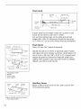
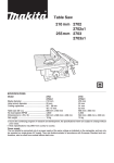
Table Saw
With Electric
BraKe
210 mm (8-1/4")
MODEL
2702Xl
MODEL
2702
255 mm (10")
MODEL
2703X1
MODEL
2703
iiiiiiiiiiiiiiiiiiiiiiiiiiiiiiiiiiiiiiiiiiiiiiiiiiii
r_
INSTRUCTION
DOUBLE
INSULATION
MANUAL
iiiiiiiiiiiiiiiiiiiiiiiiiiiiiiiiiiiiiiiiiiiiiiiiiiii
WARNING:
For your personal safety, READ and UNDERSTAND
SAVE THESE INSTRUCTIONS
www.makita.com
FOR FUTURE REFERENCE.
before using.
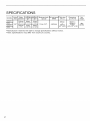
SPECIFICATIONS
MODEL
Arbor
hole
2702X1
2702
2703X1
2703
_8"
Blade
diameter
210rnrn
(8-1/4")
255rnrn
(10")
Cutting capacities
90
450
68rnm
(2-11/16")
91rnm
(3-9/16")
Maximum dado No loadspeed Tablesize
capacity
(RPM)
(Wx L)
47mm
(1-3/4")
63mm
(2-1/2")
13 mm (1/2")
• Manufacturer reserves the right to change specifications
• Note: Specifications may differ from country to country.
4,600/min
686mrn
x
560mrn
(27" x 22")
without notice.
Dimensions
(L x W x H)
560mrn x
686mrn x
458rnm
(22" x 27" x 18")
Net
weight
18kg
(40 Ibs)
For Your Own Safety Read Instruction Manual
Before Operating Table Saw
Save it for future reference
GENERAL SAFETY PRECAUTIONS
(For All Tools)
1. KNOW YOUR POWER TOOL.
Read the owner's manual carefully. Learn
the tool's applications and limitations, as
well as the specific potential hazards
peculiar to it.
9. USE RIGHT TOOL.
Don't force tool or attachment to do a job
for which it was not designed; for example,
don't use circular saw for cutting tree limbs
or logs.
2. KEEP GUARDS IN PLACE and in working order.
10. WEAR PROPER APPAREL.
Wear no loose clothing, gloves, neckties,
rings, bracelets, or other jewelry which
may get caught in moving parts. Nonslip
footwear is recommended.Wear protective
hair covering to contain long hair.
3. REMOVE ADJUSTING
KEYS AND
WRENCHES.
Form habit of checking to see that keys
and adjusting wrenches are removed from
tool before turning it on.
4. KEEP WORK AREA CLEAN.
Cluttered areas and benches invite accidents.
5. DON'T USE IN DANGEROUS
ENVIRONMENT.
Don't use power tools in damp or wet locations, or expose them to rain. Keep work
area well lighted. Don't use tool in presence of flammable liquids or gases.
6. KEEP CHILDREN AWAY.
All visitors should be kept safe distance
from work area.
7. MAKE WORKSHOP CHILD PROOF
with padlocks, master switches, or by
removing starter keys.
8. DON'T FORCE TOOL.
It will do the job better and safer at the rate
for which it was designed.
11. ALWAYS USE SAFETY GLASSES.
Also use face or dust mask if cutting operation is dusty. Everyday eyeglasses only
have impact resistant lenses, they are
NOT safety glasses.
12. SECURE WORK.
Use clamps or a vise to hold work when
practical. It's safer than using your hand
and it frees both hands to operate tool.
13. DON'T OVERREACH.
Keep proper footing and balance at all
times.
14. MAINTAIN TOOLS WITH CARE.
Keep tools sharp and clean for best and
safest performance. Follow instructions for
lubricating and changing accessories.
15. DISCONNECT TOOLS before
servicing;
when changing
accessories
such as blades, bits, cutters, and the like.
16.REDUCE
THERISKOF
UNINTENTIONAL
STARTING.
Makesureswitchisin offposition
before
plugging
in.
21. NEVERLEAVETOOLRUNNING
UNATTENDED.
TURNPOWER
OFF.
Don'tleavetooluntilit comesto a completestop.
17. USE RECOMMENDED
ACCESSORIES.
Consultthe owner'smanualfor recommended
accessories.
Theuseofimproper
accessories
maycauseriskof injuryto
persons.
18.NEVER
STAND
ONTOOL.
Seriousinjurycouldoccurif the toolis
tippedorif thecuttingtoolis accidentally
contacted.
22. Whenservicinguse onlyidentical
replacement
parts.
23.POLARIZED
PLUGS.
Toreducetheriskof electric
shock,this
equipment
hasa polarized
plug(oneblade
iswiderthantheother).
Thisplugwillfitin
a polarized
outletonlyoneway.Iftheplug
doesnotfitfullyintheoutlet,reverse
the
plug.Ifit stilldoesnotfit,contact
a qualifiedelectrician
toinstalltheproperoutlet.
Donotchange
thepluginanyway.
19.CHECK
DAMAGED
PARTS.
Beforefurtheruseofthetool,a guardor
otherpartthatisdamaged
should
becarefullychecked
todetermine
thatitwilloperateproperly
andperform
itsintended
function-checkforalignment
ofmoving
parts,
bindingof movingparts,breakage
of
parts,mounting,
andanyotherconditions
thatmayaffectitsoperation.
Aguardor
otherpartthatisdamaged
should
beproperlyrepaired
orreplaced.
VOLTAGE
WARNING:
Beforeconnecting
the toolto a power
source(receptacle,
outlet,etc.)be sure
thevoltagesupplied
is thesameasthat
specified
onthenameplate
ofthetool.A
powersourcewithvoltagegreaterthan
thatspecified
for the toolcan resultin
SERIOUS
INJURY
totheuser- aswellas
damage
to thetool.If in doubt,DONOT
PLUGIN THETOOL.Usinga power
sourcewithvoltagelessthanthenameplateratingisharmful
tothemotor.
20.DIRECTION
OFFEED.
Feedworkintoa bladeorcutteragainst
thedirection
ofrotation
ofthebladeorcutteronly.
EXTENSION
CORDS.
Makesureyourextension
cordisingoodcondition.
Whenusinganextension
cord,be
suretouseoneheawenough
tocarrythecurrent
yourproduct
willdraw.Anundersized
cordwillcausea dropinlinevoltage
resulting
inlossofpowerandoverheating.
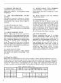
Table1
showsthecorrect
sizetousedepending
oncordlengthandnameplate
ampere
rating.If
indoubt,
usethenextheavier
gage.Thesmaller
thegagenumber,
theheavier
thecord.
Table 1. Minimum gage for cord
Ampere Rating
More than
Volts
12ov
Total length of cord in feet
2_ft I
_oft. I
loo.. I
_o..
AWG
Not more than
0
6
18
16
16
14
6
10
18
16
14
12
10
12
16
16
14
12
12
16
14
12
Not Recommended
ADDITIONAL
SAFETY RULES
DO NOT let comfort or familiarity with product (gained from repeated use) replace strict
adherence to table saw safety rules. If you use this tool unsafely or incorrectly, you can
suffer serious personal injury.
1. Wear eye protection.
2. Don't use the tool in presence
mable liquids or gases.
10. NEVER wear gloves during operation.
of flam-
3. NEVER use the tool with an abrasive
cut-off wheel installed.
4. Check the blade carefully for cracks or
damage before operation. Replace cracked
or damaged blade immediately.
5. Clean the spindle, flanges (especially
the installing surface) and hex nut before
installing the blade. Poor installation may
cause vibration/wobbling
or slippage of
the blade.
6. Use saw-blade guard and spreader for
every operation for which it can be used,
including all through sawing operations.
Always assemble and install the blade guard
following the step by step instructions outlined in this manual. Through sawing operations are those in which the blade cuts
completely through the workpiece as in
ripping or cross cutting. NEVER use the
tool with a faulty blade guard or secure the
blade guard with a rope, string, etc. Any
irregular operation of the blade guard
should be corrected immediately.
7. Immediately reattach the guard and
spreader after completing an operation which
requires removal of the guard.
8. Do not cut metals such as nails and
screws.Inspect for and remove all nails,
screws and other foreign matter from the
workpiece before operation.
9. Remove wrenches, cut-off pieces, etc.
from the table before the switch is tumed on.
11. Keep hands out of the line of the saw
blade.
12. NEVER stand or permit anyone else to
stand in line with the path of the saw
blade.
13. Make sure the blade is not contacting
the spreader or workpiece before the
switch is turned on.
14. Before cutting an actual workpiece, let
the tool run for a while. Watch for vibration
or wobbling that could indicate poor installation or a poorly balanced blade.
15. NEVER make any adjustments while
tool is running. Disconnect tool before
making any adjustments.
16. Use a push stick when required. Push
sticks MUST be used for ripping narrow
workpieces to keep your hands and fingers
well away from the blade.
17. Pay particular attention to instructions for
reducing riskof KICKBACK.KICKBACKis a sudden reaction to a pinched, bound or misaligned
saw blade. KICKBACK causes the ejection of
the workpiece from the tool back towards the
operator. KICKBACKS CAN LEAD TO SERIOUS PERSONAL INJURY. Avoid KICKBACKS
by keeping the blade sharp, by keeping the rip
fence parallel to the blade, by keeping the
spreader, antikickback pawls and blade guard
in place and operating properly, by not releasing the workpiece until you have pushed it all
the way past the blade, and by not ripping a
workpiece that is twisted or warped or does not
have a straight edge to guide along the
fence.
18.Donotperform
anyoperation
freehand.
Freehand
means
usingyourhands
tosupportorguidetheworkpiece,
inlieuofa rip
fenceormitergauge.
23.Don'tabusecord.Neveryankcordto
disconnect
fromreceptacle.
Keepcord
awayfromheat,oil, waterandsharp
edges.
19. NEVERreacharoundor oversaw
blade.NEVER
reachfora workpiece
until
thesawbladehascompletely
stopped.
24. Somematerialcontainschemicals
whichmaybetoxic.Takecaution
to preventworking
dustinhalation
andskincontact.Follow
material
supplier
safetydata.
20.Avoidabrupt,fastfeeding.Feedas
slowlyaspossible
whencutting
hardworkpieces.
Donotbendortwistworkpiece
while
feeding.
Ifyoustallorjamthebladeinthe
workpiece,
turnthetooloffimmediately.
Unplug
thetool.Thenclearthejam.
25.Theguardcanbeliftedduringworkpiecesetupandfor easeof cleaning.
Alwaysmakesurethatguardhoodis
downandflat againstsawtablebefore
plugging
inthetool.
21.NEVER
remove
cut-off
pieces
nearthe
bladeor touchthebladeguardwhilethe
bladeis running.
22.Knock
outanylooseknotsfromworkpieceBEFORE
beginning
tocut.
WARNING:
MISUSE
orfailuretofollowthesafetyrulesstatedinthisinstruction
manual
maycause
seriouspersonal
injury.
ASSEMBLY
The tool is shipped from the factory with the saw blade
and blade guard not in the installed condition. Assemble
as follows:
CAUTION:
• Always unplug the tool before assembly.
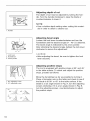
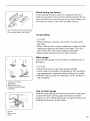
Installing saw blade
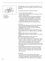
Remove the table insert on the table. Hold the outer
flange with the offset wrench and loosen the hex nut
counterclockwise with the wrench. Then remove the
outer flange.
1. Wrench
2. Offset Wrench
3. Hex nut
¢
Assemble the inner flange, blade, outer flange and hex
nut onto the arbor, making sure that the teeth of the
blade are pointing down at the front of the table. Always
install the hex nut with its recessed side facing the outer
flange.
CAUTION:
1.
2.
3.
4.
Outer flange
Hex nut
Inner flange
Saw blade
• Keep the flange surface clean of dirt or other adhering
matter; it could cause blade slippage. Be sure that the
blade is installed so that the teeth are aligned in the cutting (turning) direction.
To secure the blade in place, hold the outer flange with
the offset wrench, then tighten the hex nut clockwise
with the wrench. BE SURE TO TIGHTEN THE HEX
NUT SECURELY.
1. Wrench
2. Offset Wrench
CAUTION:
• Be sure to hold the hex nut carefully with the wrench.
If your grip should slip, the wrench may come off the
hex nut, and your hand could strike the sharp blade
edges.
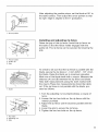
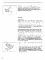
Installing blade guard
CAUTION:
• Before installing the blade guard, adjust the depth of
cut to its maximum elevation. Insert the spreader
between the blade guard mounting portion (stay) and
the pressure plate.
3
1.
2.
3.
4.
Blade guard
Spreader
Antikickback pawl
Pressure plate
3
1
6
Tighten the hex bolts (A) with the offset wrench. The
spreader installing location is factory-adjusted so that
the blade and spreader will be in a straight line.
However, if they are not in a straight line, loosen the
hex bolts (B) and adjust the blade guard mounting portion (stay) so that the spreader is aligned directly
behind the blade. Then tighten the hex bolts (B) to
secure the stay.
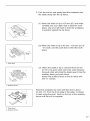
2
1. These two clearances
2.
3.
4.
5.
6.
7.
CAUTION:
should be equal
Blade guard portion
Blade
Spreader
Pressure plate
Hex bolts(A)
Hex bolts(B)
2
1
?./ i'.
(5/32" - 13/64")
4-5ram
1. Spreader
2. Blade guard
• Always grasp the striped portion of the offset wrench
when tightening the hex bolts. If you tighten the hex
bolts while grasping the offset wrench further than the
striped portion, the hex bolts may be damaged and/or
an injury to your hand may result.
• If the blade and spreader are not aligned properly, a
dangerous pinching condition may result during operation. Make sure they are properly aligned. You could
suffer serious personal injury while using the tool without a properly aligned spreader.
• NEVER make any adjustments while tool is running.
Disconnect the tool before making any adjustments.
There must be a clearance of about 4 - 5 mm (5/32" 13/64") between the spreader and the blade teeth.
Adjust the spreader accordingly and tighten the hex
bolts (A) securely. Attach the table insert on the table,
then check to see that the blade guard works smoothly
before cutting.
(18-1/16")
459
mm
334
mm 1
(13-1/8")
1.Hole
diameter
8mm(5/16")
25mm
(1"
Positioning
table saw
Locate the table saw in a well lit and level area where
you can maintain good footing and balance. It should
be installed in an area that leaves enough room to easily handle the size of your workpieces. The table saw
should be secured with four screws or bolts to the work
bench or table saw stand using the holes provided in
the bottom of the table saw. When securing the table
saw on the work bench, make sure that there is an
opening in the top of the work bench the same size as
the opening in the bottom of the table saw so the sawdust can drop through.
If during operation there is any tendency for the table
saw to tip over, slide or move, the work bench or table
saw stand should be secured to the floor.
1.6mm(1/4")
Std.
washer
2.No.10wood
screw
40mm(1-1/2") NOTE:Table
rain.
length
saw stand
• Models 2702Xl and 2703Xl
with a table saw stand.
are standard-equipped
1.6 mm (1/4") Std. washer
2.6 mm (1/4") Machine bolt & nut
tighten securely
\
1. Miter gauge
1. Rip fence
Storing accessories
The miter gauge and wrenches can be stored on the
left side of the base and the rip fence can be stored at
the rear of the base.
Adjusting
depth of cut
The depth of cut may be adjusted by turning the handle. Turn the handle clockwise to raise the blade or
counterclockwise to lower it.
NOTE:
• Use a shallow depth setting when cutting thin materials in order to obtain a cleaner cut.
1.Handle
1
1. Lock lever
2. Handwheel
3. Arrow pointer
Adjusting
bevel angle
Loosen the lock lever counterclockwise and turn the
handwheel until the desired angle (0 ° - 45 °) is obtained.
The bevel angle is indicated by the arrow pointer.
After obtaining the desired angle, tighten the lock lever
clockwise to secure the adjustment.
CAUTION:
• After adjusting the bevel, be sure to tighten the lock
lever securely.
Adjusting
positive stops
The tool is equipped with positive stops at 90 ° and 45 °
to the table surface. To check and adjust the positive
stops, proceed as follows:
1.90" adjusting screw
2.45 ° adjusting screw
(B)
10
Move the handwheel as far as possible by turning it.
Place a triangular rule on the table and check to see if
the blade is at 90 ° or 45 ° to the table surface. If the
blade is at an angle shown in Fig. A, turn the adjusting
screws clockwise; if it is at an angle shown in Fig. B,
turn the adjusting screws counterclockwise to adjust
the positive stops.
After adjusting the positive stops, set the blade at 90 ° to
the table surface. Then adjust the arrow pointer so that
its right edge is aligned to the 0° graduation.
1
1. Arrow pointer
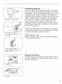
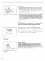
Installing and adjusting
rip fence
Raise the grip of the rip fence. Install the rip fence on
the table so that the fence holder engages with the
guide rail. The rip fence can be secured by lowering the
grip.
1. Fence holder
2. Guide rail
3. Grip
To check to be sure that the rip fence is parallel with the
blade, secure the rip fence 2 - 3 mm (5/64" - 1/8" ) from
the blade. Raise the blade up to maximum elevation.
Mark one of the blade teeth with a crayon. Measure the
distance (A) and (B) between the rip fence and blade.
Take both measurements using the tooth marked with
the crayon.These two measurements should be identical. If the rip fence is not parallel with the blade, proceed as follows:
A
1. Scale
1. Turn the adjusting nut counterclockwise a couple of
turns.
2. Loosen the two hex bolts on the rip fence with the
wrench provided.
3. Adjust the rip fence until it becomes parallel with the
blade.
4. Lower the grip to secure the rip fence.
5. Tighten the two hex bolts on the rip fence.
1
3
1. Hex bolts
2. Adjusting nut
3. Grip
11
CAUTION:
• Always grasp the striped portion of the wrench when
tightening the hex bolts. If you tighten the hex bolts
while grasping the wrench further than the striped portion, the hex bolts may be damaged and/or an injury
to your hand may result.
6. With the grip of the rip fence lowered, turn the adjusting nut clockwise to secure the rear end of the rip
fence. Do not turn the adjusting nut clockwise excessively. You may have some difficulty adjusting the rip
fence parallel with the saw blade when repositioning
the rip fence.
CAUTION:
Be sure to adjust the rip fence so that it is parallel with the
blade, or a dangerous kickback condition may occur.
Bring the rip fence up flush against the side of the
blade. Make sure that the arrow pointer on the fence
holder points to the 0 graduation. If the arrow pointer
does not point to the 0 graduation, loosen the screw on
the scale plate and adjust the scale plate.
3
4
1. Screw
2. Fence holder
3. Scale plate
4. Arrow mark
1
2
1. Switch lever
2. Key
12
Switch
action
This tool is equipped with a special type of switch to
prevent unintentional starting. To start the tool, first
depress the switch lever.While keeping it depressed,
pull its lower portion toward you. To stop the tool, press
the lower portion of the switch lever.
When operating the switch lever, it is convenient
view it through the window area in the table.
to
CAUTION:
• When not using the tool, remove the key and store it
in a secure place. This prevents unauthorized operation.
• Before plugging in the tool, always check to see that
the switch lever actuates properly and returns to the
"OFF" position.
• Do not pull the switch lever hard without the key. This
can cause breakage of the switch.
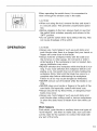
OPERATION
CAUTION:
• Always use "work helpers" such as push sticks and
push blocks when there is a danger that your hands or
fingers will come close to the blade.
• Always hold the workpiece firmly with the table and
the rip fence or miter gauge. Do not bend or twist it
while feeding. If the workpiece is bent or twisted, dangerous kickbacks may occur.
• NEVER withdraw the workpiece while the blade is running. If you must withdraw the workpiece before completing a cut, first switch the tool off while holding the
workpiece firmly. Wait until the blade has come to a
complete stop before withdrawing the workpiece.
Failure to do so may cause dangerous kickbacks.
• NEVER remove cut-off material while the blade is running.
• NEVER place your hands or fingers in the path of the
saw blade. Be especially careful with bevel cuts.
• Always secure the rip fence firmly, or dangerous kickbacks may occur.
• Always use "work helpers" such as push sticks and
push blocks when cutting small or narrow workpieces,
or when the dado head is hidden from view while cutting.
Work helpers
Push sticks, push blocks or auxiliary fence are types of
"work helpers". Use them to make safe, sure cuts without the need for the operator to contact the blade with
any part of the body.
13
Push stick
(H)
9.5 mrn
19 mm@_
(3/4)
_
130 rnm (5")
9.5 mm
_'i;'_"_
Y
I (50')mm
g80 mm (15")
\
A push stick can be easily made from a piece of plywood 19 mm (3/4") to 25 mm (1") thick.
Cut out the hatched area on the stick and smooth
edges with a file. (H) dimension should be less than
12.7 mm (1/2") so as to be thinner than the workpiece.
120 mT1
I
300 Tim(2")
6 ram (1/4") j
2
_
Push block
Use a 19 mm (3/4") piece of plywood.
I
_ 50ram (2")
.___
/_
(5")
300 mm (12")
Handle should be in center of plywood piece. Fasten
with glue and wood screws as shown. Small piece 9.5
mm x 8 mm x 50 mm (3/8" x 5/16" x 2") of wood must
always be glued to plywood to keep the blade from
dulling if the operator cuts into push block by mistake.
(Never use nails in push block.)
5_Zr,_)m
130 mm _
9.5 mm (3/8")4
50 ram (2") _"_
,_
100 mm (4")
8 mm (5/16")
1. Face/edge parallel
2. Handle
3. Wood screw
4. Glue together
9.5mm
19mm
120ram
(3/8")
(3/4")
(4-3/4")
460 mm (18"
140 mm
(5-1/2")
Fasten with glue and wood screws.
1. Face/edge parallel
14
Auxiliary fence
Make auxiliary fence from 9.5 mm (3/8") and 19 mm
(3/4") plywood pieces.
Wood facing (rip fence)
A wood facing should be used for operations when the
blade comes close to the rip fence. Wood facing for the rip
fence should be the same size as the rip fence. Make sure
the bottom of facing is flush with the table surface.
1
1. No. 10 wood screws (long enough
to penetrate halfway into facing)
Crosscutting
CAUTION:
• When making a crosscut, remove the rip fence from
the table.
• When cutting long or large workpieces, always provide
adequate support to the sides of the table. The support should be at the same height as the table.
• Always keep hands away from path of blade.
Miter gauge
Use the miter gauge for the 4 types of cutting shown in
the figure.
CAUTION:
• Secure the knob on the miter gauge carefully.
• Avoid creep of workpiece and gauge by firm workholding arrangement, especially when cutting at an angle.
• NEVER hold or grasp the intended "cut-off" portion of
the workpiece.
1.
2.
3.
4.
CROSS CUTTING
MITERING
BEVEL CUTTING
COMPOUND MITERING
(ANGLES)
Use of miter gauge
Slide the miter gauge into the thick grooves in the table.
Loosen the knob on the gauge and align to desired
angle (0 ° to 60°). Bring stock flush up against fence and
feed gently forward into the blade.
1. Groove
2. Miter gauge
3. Knob
15
Auxiliary wood facing (miter gauge)
To prevent a long board from wobbling, fit the miter
gauge with an auxiliary fence board. Fasten with
bolts/nuts after drilling holes, but fasteners must not
protrude from the face board.
Ripping
CAUTION:
• When ripping, remove the miter gauge from the table.
• When cutting long or large workpieces, always provide
adequate support behind the table. DO NOT allow a
long board to move or shift on the table. This will
cause the blade to bind and increase the possibility of
kickback and personal injury. The support should be at
the same height as the table.
Before operating the table saw, check to be sure that
the antikickback pawls operate properly. Turn the tool
off and unplug it. Feed the workpiece under the blade
guard and along both sides of the blade to simulate cutting. Try to withdraw the workpiece on each side by
pulling it toward you. The antikickback pawls should
grab the workpiece and prevent it from moving back
toward the operator. Always keep the antikickback
pawls sharp so they will operate properly. Keep them
sharp by using a round-shaped file to maintain the original shape of the pawls.
1. Adjust the depth of cut a bit higher than the thickness
of the workpiece.
2. Position the rip fence to the desired width of rip and
lock in place by lowering the grip. Before ripping,
make sure the rear end of the rip fence is secured
firmly. If it is not secured enough, follow the procedures in "Installing and adjusting rip fence" described
on page 11 and 12.
16
3. Turn the tool on and gently feed the workpiece into
the blade along with the rip fence.
(1) When the width of rip is 150 mm (6") and wider,
carefully use your right hand to feed the workpiece. Use your left hand to hold the workpiece
in position against the rip fence.
(2) When the width of rip is 65 mm - 150 mm (2-1/2"
- 6") wide, use the push stick to feed the workpiece.
1. Push stick
(3) When the width of rip is narrower than 65 mm
(2-1/2"), the push stick cannot be used because
the push stick will strike the blade guard. Use the
auxiliary fence and push block.
Attach the auxiliary fence to the rip fence with
two "C" clamps.
1. Auxiliary fence
Feed the workpiece by hand until the end is about
25 mm (1") from the front edge of the table. Continue
to feed using the push block on the top of the auxiliary
fence until the cut is complete.
1. Push block
2. Auxiliary fence
17
MAINTENANCE
CAUTION:
• Always be sure that the tool is switched off and
unplugged before attempting to perform inspection or
maintenance.
Cleaning
Clean out sawdust and chips from time to time.
Carefully clean the blade guard and moving parts inside
the table saw.
Lubrication
To keep the table saw in tip-top running condition, and
to assure maximum service life, oil or grease the moving parts and rotating parts from time to time.
Lubrication places:
• Threaded shaft to elevate the blade
• Hinge to rotate the frame
• Elevation guide shafts on motor
• Gear to elevate the blade
Replacing
carbon brushes
Remove and check the carbon brushes regularly.
Replace when they wear down to the limit mark. Keep
the carbon brushes clean and free to slip in the holders.
Both carbon brushes should be replaced at the same
time. Use only identical carbon brushes.
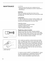
1. Limit mark
Use a holder cap opener to remove the brush holder
caps. To replace the carbon brush in the side near the
table, lower the blade as far as possible by turning the
handle. Loosen the lock lever, tilt the blade and secure
it at 45 ° . Then loosen the brush holder cap while viewing it through the opening of the base. Remove the
worn carbon brushes, insert the new ones and secure
the brush holder caps.
1. Holder cap opener
2. Brush holder cap
To maintain product SAFETY and RELIABILITY, repairs,
any other maintenance or adjustment should be performed by Makita Authorized or Factory Service
Centers, always using Makita replacement parts.
18
ACCESSORIES
CAUTION:
• These accessories or attachments are recommended
for use with your Makita tool specified in this manual.
The use of any other accessories or attachments
might present a risk of injury to persons.
Only use accessory or attachment for its stated purpose.
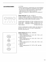
Dado head set (Part No. 191543-4)
A dado is cutting a rabbet or a wide groove into the
workpiece. The dado head set consists of two outside
cutters, three inside cutters and paper washers.
1/8"
1/8"
1/16"
1/8"
1/8"
Outside cutters: 6"diameter 1/8" thick, 5/8"arbor hole,
Inside cutters: 6"diameter 1/8"thick, 5/8"arbor hole,
Inside cutter:
6"diameter 1/16"thick, 5/8"arbor hole,
Paper washers:
8/8"arbor hole,
2
2
1
6
pcs.
pcs.
pc.
pcs.
Various combinations of these cutters are used to cut
grooves from 1/8" to 1/2" for use in making joints,
tenoning, grooving, etc.
/
//
2
s
Dado flange set (Part No.
1. Dado outer flange
When cutting groove 1/4",
use this dado outer flange.
2. Dado hex nut
When cutting groove 1/4",
use this dado hex nut.
3. Ring
When cutting groove 1/4",
use this ring.
4. Washer
When cutting groove 1/4",
washer.
192693-8)
5/16", 3/8", 7/16" or 1/2",
5/16", 3/8", 7/16" or 1/2",
5/16", 3/8", 7/16" or 1/2",
5/16" or 3/8", use this
X_
19
Table insert
(Part No. 317061-6)
When cutting grooves 5/16% 3/8",7/16" or 1/2" use this
table insert instead of the standard table insert.
To install the dado head set, proceed as follows:
1. Turn the tool off and unplug it before installing.
2. Remove the blade guard with the spreader.
3. Install the dado head set with the teeth pointing down
at the front of the table.
4. Use the chart below to select the proper cutters to
obtain the various cutting widths.
Spindle
Inner
:lange
Ring
Outside
Cutter
1/8"
Inside
cutter
1/16"
Inside
cutter
f'-\
CUT
WIDTH
Outside
cutter
Outer
flange
Washer
Dado
Outer
flange
Dad{
Hex Hex
nut nut
f_,\
@
1/8"
•
1/4"
•
•
•
5/16"
•
•
•
3/8"
•
•
•
7/16"
•
•
•
1/2"
•
•
•
•
•
•
•
•
•
Ox2
•
•
•
•
•
•
•
•
•
•
•
•
•
•
•
•
•
•
•
•
CAUTION:
• For a 1/8" cut width, the outside cutter is assembled to
the spindle in the same manner as the saw blade.
• The outer flange or the dado outer flange must be
used for each cut width.
• The hex nut alone must not be used to secure the
dado on to the spindle.
20
NOTE:
• When widths slightly greater than the above are
required, fit the paper washers in between the inside
and outside cutters to adjust the width.
1
2
3
5. Arrange the cutters so that the tips of the inside cutters are positioned at the gullets of the outside cutter.
When more than one inside cutter is used, space
the tips of the inside cutters equidistantly in relation
to one another. Poorly spaced cutters may cause
vibration and noise.
1, Inside cutter
2, Outside cutter
3. Gullet
When installing two outside cutters without any inside
cutter, be sure that the cutter tips do not face each
other.
6. While tightening the hex nut, be careful to maintain the
even spacing between the tips of the inside cutters.
7. Rotate the dado head one turn by hand to make sure
that it does not contact anything before operation.
When dadoing, use featherboards. The diagram shown
illustrates dimensions for making a typical featherboard.
It should be made from a straight piece of wood that is
free of knots or cracks.
19ram
115mm
(3/4")
(4-1/2")
1. Kerf should be about 6 rnrn
(1/4") apart
21
Featherboards are used to keep the workpiece in contact with the rip fence and table as shown, and to stop
kickbacks.
1
i
•
-2
_
/#
3
1.
2,
3,
4,
"C"Clarnps
Facing board
Featherboard
Push stick
To install featherboards,
proceed as follows:
1. Turn the tool off and unplug it.
2. Add 8" high flat facing board to the rip fence, the full
length of the rip fence.
3. Mount featherboards to the rip fence and table as
shown, so that the leading edges of the featherboards will support the workpiece until the cut is
completed, and the workpiece has been pushed
completely past the cutter with a push stick.
4. Make sure featherboards are securely attached.
CAUTION:
• Only the Makita dado head set (Part No. 191543-4)
should be used with Makita table saw Model
2702/Model 2703. Do not use dado combinations
wider than 13 mm (1/2").
• After dadoing, ALWAYS replace the blade guard with
the spreader back in its original position on the table
saw.
• NEVER attempt bevel cuts when dadoing.
• NEVER dado if there is vibration (flutter) or a strange
noise.
• NEVER attempt dados in other than wood.
• Do not use the dado set for cut-offs.
• Feed work slowly, especially when cutting deep or wide
grooves or dados. If a deep cut is needed, make several
passes through the workpiece rather than one deep,
wide cut. Fast or abrupt feeds can be dangerous.
• Use a push stick. When the dado head is hidden from
view while cutting, your hands should never be on top
of the stock.
• A very dangerous throwback can result if the wood
becomes stuck and you try to remove it by pulling
toward you. Always stop the tool and wait for dado
head to come to a complete stop. Then simply withdraw the wood.
WARNING:
22
• Use extra caution when the guard assembly is
removed for any non-through sawing operation such
as dadoing, rabbeting or resawing. Replace guard
immediately after non4hrough sawing is completed.
1
1. Rabbet
2. First cut
3. Second cut
3
How to perform rabbeting
1. Remove blade guard.
2. Attach auxiliary fence to rip fence for cuts that run the
length of the stock. Facing should be as high as the
workpiece is wide. Adjust fence and blade to desired
dimensions.
3. First cut: Hold board flat on table as in ordinary ripping.
4. Second cut: Set workpiece on its edge. (Use featherboards, push stick, push block and so on, using precautions, safety rules and guidelines for ripping or
related work.)
5. For end-type rabbeting, if the workpiece is less than
10-1/2" wide, rest the wood flat on the table against
the miter gauge (with wood facing). The rip fence
should not be used.
6. After rabbeting is completed, immediately re-install
the blade guard as before.
Table saw stand
Place the stays on
legs inside. Secure
the rubber caps to
1.
2.
3.
4.
5.
(Part No. 192680-7)
a level location and assemble the
with the bolts and nuts, then attach
the ends of the legs.
Rubber cap
Nut
Leg
Under stay
Stay
Now set the table saw on top of the assembled stand
and secure with four bolts, washers and nuts.
NOTE:
• Models 2702Xl and 2703Xl
with a table saw stand.
are standard-equipped
1. Bolt
2. Stand
23
ACCESSORIES
CAUTION:
• These accessories or attachments are recommended
for use with your Makita tool specified in this manual.
The use of any other accessories or attachments
might present a risk of injury to persons. Only use
accessory or attachment for its stated purpose.
If you need any assistance for more details regarding
these accessories, ask your local Makita service center.
• Steel
& Carbide-tipped
saw blades
Table/Miter saw
blades
For general purpose cuts for
table and miter saws.
Combination
General purpose blade for fast and
smooth rip, crosscuts and miters.
Fine cross cuts
For sand-free cuts cleanly against
the grain.
•
•
•
•
•
•
•
•
24
Sub-Table set ( Left / Right )
Rip fence
Miter gauge
Offset wrench 13-22
Wrench 19
Key (Switch button)
Holder cap opener
Joint ( for connecting to dust collector )
I
I
First-Class
Postage
Required
o
Post
not
without
Office
p_oper
postage
Makita U.S.A., inc.
14930 Northam Street
La Mirada, CA 90638-5753
Ul,l,ulh,u,ll,u,,llul,,lu,hlul,,,U,hlu,,llu,h,Ul
----
Fold
will
deliver
Your answers to the following
1, Th_
[]
product
was, purchased
Home Center
]Hardware/Lumber
[]hdustrial
1tom:
3, How d_d you _earn about th_
[]
Magazine
[]
Radii)
[]
From DeaJer
[]
Exhibition
[]
Newspaper
[]
From Friend
[]
Store Display
[]
Previous
[]
Catalog
[]
Other(
Other (
Supply
]Industrial
_ _ntended
1or:
4, Most _avored points
Maintenance
Home Maintenance
[]
Hobby
[]
Other (
are appreciated.
[]
Store
2, Use ol the product
]
questions
Usage
are:
[]
Design
[]
Repair Service
[]
Features
[]
Durability
[]Size
)
product:
[]Power
[]
Price
]
Makita
[]
Other(
Brand
5=Any comment_:
DATE PURCHASED
MONTH
DAY
MODEL
NO.
SERIAL
NO.
YEAR
STATUS
INTL.
LAST NAME / COMPANY
NAME
Married
1
STREET
SEX
M
Single
!
I
I
I
I
I
I
I
F
!
I
I
I
I
ADFtESS
I
CITY
STA-[ E
ZIP CODE
AREA
CODE
PHONE
I
AGE:
BE SURE
_J
UI,der 19
TO COMPLETE
THE
_J
20-29
CUSTOMERS
_J
30-39
PORTION
OF THIS
_J
40-49
FORM
AND
_J
50-60
RETAIN
Please return this portion by facsimile
_J
FOR YOUR
Over 60
I
I
I
I
I
I
I
I
I
I
RECORDS,
or mail.
Facsimile No: (714) 522_8!33
i
I
CE
1-800-4-MAK]TA
RETAIN THIS PORTION
ALABAMA
COLORADO
2365 Pelham Rat kway
Pelham
AL 35124
1183c_ E 51st Ave
DenJe_
CO 80239
(205) 620 1791
(303)
,&RIZON,¢
3707 E Broadway Rd Ste 6
_'hoenix AZ 85O4O
_502_437 2350
ARKANS,¢S
S11ackletol
d Shopl_ng Center
240Soutl/ Sha_kleto_dRd
St÷ C
Utt_eao_k AR 72211
_50t_224:373_
CALIFORNIA
4185O OhristySt
_remol/t O,€ _4:S3_ 5107
_5t0_557 9t_81
2709
371 2850
FLORIDA
620 Douglas Ave Suite t 302
AJtamol/teSprings FL 32714
_407_774 6OOO
75O East Sample Road
_'ompa_o Beach FL 33O64
_9:34) 781 633_
Thompson Oente_Waters
5501 W Waters Ave¸¸ Ste 405
Tampa FL33634
_t3_ 886 8292
_EORGI,¢
468ORive_ Green Pa_kv,_y
Dulut_/GA 3OO962556
_770_476 8_11
t421 N Clovis Ave ._te t12
_resno OA _3727
_5:S
g_ 252 5156
t4930 Northam St
La _irada CA 9063_ _753
_714_522 808_
t970 Fultol/Avenue
Sa,_mento CA 95525
_916_482 5197
ILLINO_S
t450 Fee_/an'_i_le_)r
Mt _ros_ect IL 60055 5011
_47_ 297 3100
_ND_ANA
_40_ bl_c_/igan Road¸ Unit 1
_ndianapoli_ IN 4625_
_317_334 9_80
t440 South E _Stleet
San_e_l/ardil/o CAg2408
_909_885 t289
7574Cla_rernol/tMesa _lvd
San Diego¸CA 92111
_58_ 278 4471
tSS_W4n,_hester_
Campbell CA 95O08 0501
_408_379 0377
KANSAS
_19 W 95t_/St
Overland Pa_k KS 56212
_913_542 t111
KENTOCK¥
t21_ S H_lstbourne Parkway
Louisville _4¥4O222
_502_326 374O
FOR YOUR RECORDS
LOUISIANA
II EW 'CORK
_OEP,'fO
5626 Jefferson
H_y
H_rahal/
LA 70123
4c_17 Ge41essee Street
( heektowaga
NY 14225
200 Guayama
St
Hato Rey PR 00917
(504)
(716/685
(787/2:30
733 4138
MARYLANB
7541 4:SR4tchie Highway
Glen Bu_nie f,4D21061
_410_:Sg00150
,_AS_,CCHUSETTS
232 Prov_denr__4W,/
Westwood MA O209O
_617_461 g754
_NNESO'r,_
6427 Penn Ave South
Iqichfield MN 55423
_612_86_ 5199
NORTH CA ROL_N,&
3501 G S _yon St
Charlotte NO23217
_704_527 0611
S'EF4NESSEE
4655 Nolel/_ville Rd
Nashville TN 37211
(615_3_1 9922
TEXAS
12B01 Stemmolls Fv,'ySte B09
F_rmers _ranch TX 75234
(_72_243 1iS0
12701 Director_ Dr
Stattor_ TX 77477 3701
(28t_ 5558665
6379 Pearl Road
_'a_maHeights OH 4413O
_440_843 7555
3453 _H3_ No_t_/St÷ 101
Sal/A ntollio, TX 7_21
(210_228 0675
t617 E Kempe_Rd
Sharowille OH 45246
_513_771 07_8
NEBRASKA
4129 S _4_hSt
Oma_ NE 6_t27
_402_597 2_25
O KL,_HOMA
:%2 E t,4emoria_Road
Oklahoma City O_<73114
_405_752 2655
NEV,CB_
3375 S Decatur _vd
Suites 22 24
Las Vegas¸ NV 89t02
_702_36_4277
OREGON
_28 t_t_/,¢venue NW
_'olt_al/d ORg7209
_503_222 t823
NEW JERSEY
251 Her_odt_lvd
D_yton NJ08_I0
_609_555 t212
pENNSYLWNIA
Springwate_ r'laza
364 Wilmlngtol/W Cheste_
_'lke
Glen blill_ PA t9342
_610_4:S_ 4122
153_
8776
O'a_O
6253 E Ma_nS_
Oolumbus OH 43213
_614_86O 0222
,_SSOUP4
_876 Watson Road
St Lo_s blO 63126 2221
_314_90_ gB89
t6735 Satlcoy St, Ste 105
Van Nuys CA _14O6
_818_782 2440
CUSTOMER'S
9503
t31 35 3tst Ave
Flusl/mg N¥ 11354
_718_886 0971
RiCO
UTAH
t45 E 1300S S_e t01
Salt Lake City,UT 8411:S
(_0t_ 359 3410
WAShiNGTON
2222O84th Ave So _ld_ A
}<e41tWA _ts032
(253_395 8055
W_SCONSlN
Un_o_n_]aza Shopping Ctr
2245 S 108th ._t West AIlis W[
53227
(414_ 5414775
62OOBabcock Bird
_qtl_balgh, PA 15237
_412_366 5363
RECORD
When you need service: Send
Date P_Jrchased
complele tool (prepaid)to oi/e
of the Makita FactoryService
Dea]er's Name & Address
CentersHsted,otto anAuthorized
blakita Service Centel.Be sure
to attacha letterto the outside of
the carton detailingthe prob]em
Model No.
with you_tool
Serial No
27
Some dust created by power sanding, sawing, grinding, drilling, and other
construction activities contains chemicals known to the State of California
to cause cancer, birth defects or other reproductive harm, Some examples
of these chemicals are:
lead from bad=based paints,
o crystalline silica from bricks and cement and other masonry products, and
o arsenic and chromium from chemically=treated lumber,
Your risk from these exposures varies, depending on how often you do this
type of work, To reduce your exposure to these chemicals: work in a wen
ventilated area, and work with approved safety equipment, such as those
dust masks that are specially designed to filter out microscopic particles,
MAKITA LIMITED ONE YEAR WARRANTY
Warranty
Policy
Every Makita tool is thoroughly inspected and tested before leaving the factory. It is warranted to be free of
defects from workmanship and materials for the period of ONE YEAR from the date of original purchase,
Should any trouble develop during this one year period, return the COMPLETE tool, freight prepaid, to one of
Makita's Factory or Authorized Service Centers. If inspection shows the trouble is caused by defective
workmanship or material, Makita will repair (or at our option, replace) without charge.
This Warranty
does not apply where:
* repairs have been made or attempted
repairs are required because
the tool has been abused
alterations
by others:
of normal wear and tear:
misused or improperly
maintained:
have been made to the tool,
IN NO EVENT SHALL MAKITA BE LIABLE FOR ANY INDIRECT, INCIDENTAL OR CONSEQUENTIAL
DAMAGES FROM THE SALE OR USE OFTHE PRODUCT. THIS DISCLAIMER APPLIES BOTH DURING
AND AFTER THE TERM OF THIS WARRANTY.
MAKITA DISCLAIMS
"MERCHANTABILITY"
WARRANTY
LIABILITY FOR ANY IMPLIED WARRANTIES,
INCLUDING IMPLIED WARRANTIES OF
AND "FITNESS FOR A SPECIFIC PURPOSE," AFTER THE ONE YEAR TERM OF THIS
This Warranty gives you specific legal rights, and you may also have other rights which vary from state to state.
Some states do not allow the exclusion or limitation of incidental or consequential damages, so the above
limitation or exclusion may not apply to you, Some states do not allow Nmitation on how long an implied
warranty lasts, so the above limitation may not apply to you.
Makita Corporation
of America
2650 Buford Hwy., Buford, GA 30518
884129C060