1
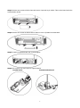
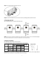
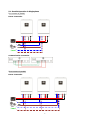
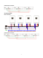
PIP-HS/MS Series Parallel Installation Guide 1. Introduction This inverter can be used in parallel with two different operation modes. 1. Parallel operation in single phase with up to 6 units. The supported maximum output power is 24KW/30KVA. 2. Maximum six units work together to support three-phase equipment. Four units support one phase maximum. The supported maximum output power is 24KW/30KVA and one phase can be up to 16KW/20KVA. NOTE: If this unit is bundled with share current cable and parallel cable, this inverter is default supported parallel operation. You may skip section 3. If not, please purchase parallel kit and install this unit by following instruction from professional technical personnel in local dealer. 2. Package Contents In parallel kit, you will find the following items in the package: Parallel board Parallel communication cable Current sharing cable 3. Parallel board installation This installation steps are only applied to 4K/5K models. Step 1: Remove wire cover by unscrewing all screws. Step 2: Remove communication board by unscrewing two screws as below chart. 1 Step 3: Remove two screws as below chart and remove 2-pin and 14-pin cables. Take out the board under the communication board. Step 4: Remove two screws as below chart to take out cover of parallel communication. Step 5: Install new parallel board with 2 screws tightly. Step 6: Re-connect 2-pin and 14-pin to original position. Parallel board Communication board 2 Step 7: Put communication board back to the unit. Step 8: Put wire cover back to the unit. Now the inverter is providing parallel operation function. 4. Mounting the Unit When installing multiple units, please follow below chart. NOTE: For proper air circulation to dissipate heat, allow a clearance of approx. 20 cm to the side and approx. 50 cm above and below the unit. Be sure to install each unit in the same level. 5. Wiring Connection The cable size of each inverter is shown as below: Recommended battery cable and terminal size for each inverter: Ring Terminal Torque Cable Dimensions Model Wire Size value D (mm) L (mm) mm2 4KVA 5KVA 1*4AWG 22 6.4 33.2 2*8AWG 14 6.4 29.2 1*4AWG 22 6.4 33.2 2*8AWG 14 6.4 29.2 Ring terminal: 2~ 3 Nm 2~ 3 Nm WARNING: Be sure the length of all battery cables is the same. Otherwise, there will be voltage difference between inverter and battery to cause parallel inverters not working. 3 Recommended AC input and output cable size for each inverter: Model AWG no. Torque 4KVA 10 AWG 1.4~1.6Nm 5KVA 8 AWG 1.4~1.6Nm You need to connect the cables of each inverter together. Take the battery cables for example: You need to use a connector or bus-bar as a joint to connect the battery cables together, and then connect to the battery terminal. The cable size used from joint to battery should be X times cable size in the tables above. “X” indicates the number of inverters connected in parallel. Regarding AC input and output, please also follow the same principle. CAUTION!! Please install the breaker at the battery and AC input side. This will ensure the inverter can be securely disconnected during maintenance and fully protected from over current of battery or AC input. The recommended mounted location of the breakers is shown in the figures in 5-1 and 5-2. Recommended breaker specification of battery for each inverter: Model 1 unit* 4KVA 80A/60VDC 5KVA 100A/60VDC *If you want to use only one breaker at the battery side for the whole system, the rating of the breaker should be X times current of 1 unit. “X” indicates the number of inverters connected in parallel. Recommended breaker specification of AC input with single phase: Model 2 units 3 units 4 units 5 units 6 units 4KVA 80A/230VAC 120A/230VAC 160A/230VAC 200A/230VAC 240A/230VAC 5KVA 100A/230VAC 150A/230VAC 200A/23VAC 250A/23VAC 300A/23VAC Note1: Also, you can use 40A breaker (50A for 5KVA) for only 1 unit, and each inverter has a breaker at its AC input. Note2: Regarding three phase system, you can use 4 poles breaker, the rating is up to the current of the phase which has the maximum units. Or you can follow the suggestion of note 1. Recommended battery capacity Inverter parallel numbers 2 3 4 5 6 Battery Capacity 400AH 600AH 800AH 1000AH 1200AH WARNING! Be sure that all inverters will share the same battery bank. Otherwise, the inverters will transfer to fault mode. 4 5-1. Parallel Operation in Single phase Two inverters in parallel: Power Connection N L N Load L Communication Connection Three inverters in parallel: Power Connection N L N Load L 5 Communication Connection Four inverters in parallel: Power Connection N L N Load L Communication Connection 6 Five inverters in parallel: Power Connection N L N Load L Communication Connection Six inverters in parallel: Power Connection N L N Load L Communication Connection 7 5-2. Support 3-phase equipment Two inverters in each phase: Power Connection P1 P2 P3 N L1 L2 L3 Load N L1 L2 L3 Communication Connection Four inverters in one phase and one inverter for the other two phases: Power Connection P2 P1 N L1 L2 L3 Load N L1 L2 L3 Note: It’s up to customer’s demand to pick 4 inverters on any phase. P1: L1-phase, P2: L2-phase, P3: L3-phase. 8 P3 Communication Connection Three inverters in one phase, two inverters in second phase and one inverter for the third phase: Power Connection P1 P2 N L1 L2 L3 Load N L1 L2 L3 Communication Connection 9 P3 Three inverters in one phase and only one inverter for the remaining two phases: Power Connection P2 P1 P3 N L1 L2 L3 Load N L1 L2 L3 Communication Connection Two inverters in two phases and only one inverter for the remaining phase: Power Connection P1 P2 N L1 L2 L3 Load N L1 L2 L3 10 P3 Communication Connection Two inverters in one phase and only one inverter for the remaining phases: Power Connection P2 P1 N L1 L2 L3 Load N L1 L2 L3 Communication Connection 11 P3 One inverter in each phase: Power Connection P2 P1 P3 N L1 L2 L3 Load N L1 L2 L3 Communication Connection WARNING: Do not connect the current sharing cable between the inverters which are in different phases. Otherwise, it may damage the inverters. 6. PV Connection Please refer to user manual of single unit for PV Connection. CAUTION: Each inverter should connect to PV modules separately. 12 7. LCD Setting and Display Setting Program: Program Description Selectable option Single: When the units are used in parallel with single phase, please select “PAL” in program 28. It is required to have at least 3 inverters or maximum 6 inverters to support three-phase equipment. It’s required to have at least one inverter in each phase or it’s up to four inverters in one phase. Please refers to 5-2 for detailed information. Please select “3P1” in program 28 for the inverters connected to L1 phase, “3P2” in program 28 for the inverters connected to L2 phase and “3P3” in program 28 for the inverters connected to L3 phase. Parallel: 28 AC output mode *This setting is only available when the inverter is in standby mode (Switch off). L1 phase: L2 phase: Be sure to connect share current cable to units which are on the same phase. Do NOT connect share current cable between units on different phases. L3 phase: Besides, power saving function will be automatically disabled. One Inverter (Default): 30 PV judge condition (Only apply for setting “Solar first” in program 1: Output source priority) All of Inverters: 13 When “ONE” is selected, as long as one of inverters has been connected to PV modules and PV input is normal, parallel or 3-phase system will continue working according to rule of “solar first” setting. For example, two units are connected in parallel and set “SOL” in output source priority. If one of two units has connected to PV modules and PV input is normal, the parallel system will provide power to loads from solar or battery power. If both of them are not sufficient, the system will provide power to loads from utility. When “ALL” is selected, parallel or 3-phase system will continue working according to rule of “solar first” setting only when all of inverters are connected to PV modules. For example, two units are connected in parallel and set “SOL” in output source priority. When selecting “ALL” in program 30, it’s necessary to have all inverters connected to PV modules and PV input is normal to allow the system to provide power to loads from solar and battery power. Otherwise, the system will provide power to loads from utility. Fault code display: Fault Code Fault Event 60 Power feedback protection 71 Firmware version inconsistent 72 Current sharing fault 80 CAN fault 81 Host loss 82 Synchronization loss 83 Battery voltage detected different 84 AC input voltage and frequency detected different 85 AC output current unbalance 86 AC output mode setting is different Icon on 8. Commissioning Parallel in single phase Step 1: Check the following requirements before commissioning: Correct wire connection Ensure all breakers in Line wires of load side are open and each Neutral wires of each unit are connected together. Step 2: Turn on each unit and set “PAL” in LCD setting program 28 of each unit. And then shut down all units. NOTE: It’s necessary to turn off switch when setting LCD program. Otherwise, the setting can not be programmed. Step 3: Turn on each unit. LCD display in Master unit LCD display in Slave unit NOTE: Master and slave units are randomly defined. 14 Step 4: Switch on all AC breakers of Line wires in AC input. It’s better to have all inverters connect to utility at the same time. If not, it will display fault 82 in following-order inverters. However, these inverters will automatically restart. If detecting AC connection, they will work normally. LCD display in Master unit LCD display in Slave unit Step 5: If there is no more fault alarm, the parallel system is completely installed. Step 6: Please switch on all breakers of Line wires in load side. This system will start to provide power to the load. Support three-phase equipment Step 1: Check the following requirements before commissioning: Correct wire connection Ensure all breakers in Line wires of load side are open and each Neutral wires of each unit are connected together. Step 2: Turn on all units and configure LCD program 28 as P1, P2 and P3 sequentially. And then shut down all units. NOTE: It’s necessary to turn off switch when setting LCD program. Otherwise, the setting can not be programmed. Step 3: Turn on all units sequentially. LCD display in L3-phase unit LCD display in L1-phase unit LCD display in L2-phase unit Step 4: Switch on all AC breakers of Line wires in AC input. If AC connection is detected and three phases are matched with unit setting, they will work normally. Otherwise, the AC icon will flash and they will not work in line mode. LCD display in L1-phase unit LCD display in L2-phase unit LCD display in L3-phase unit Step 5: If there is no more fault alarm, the system to support 3-phase equipment is completely installed. Step 6: Please switch on all breakers of Line wires in load side. This system will start to provide power to the load. Note 1: To avoid overload occurring, before turning on breakers in load side, it’s better to have whole system in operation first. Note 2: Transfer time for this operation exists. Power interruption may happen to critical devices, which cannot bear transfer time. 15 9. Trouble shooting Situation Fault Code 60 71 72 80 81 82 83 84 85 86 Solution Fault Event Description Current feedback into the inverter is detected. The firmware version of each inverter is not the same. The output current of each inverter is different. CAN data loss Host data loss Synchronization data loss The battery voltage of each inverter is not the same. AC input voltage and frequency are detected different. AC output current unbalance AC output mode setting is different. 1. 2. 3. 4. 1. 2. 3. Restart the inverter. Check if L/N cables are not connected reversely in all inverters. For parallel system in single phase, make sure the sharing are connected in all inverters. For supporting three-phase system, make sure the sharing cables are connected in the inverters in the same phase, and disconnected in the inverters in different phases. If the problem remains, please contact your installer. Update all inverter firmware to the same version. Check the version of each inverter via LCD setting and make sure the CPU versions are same. If not, please contact your instraller to provide the firmware to update. After updating, if the problem still remains, please contact your installer. 1. 2. Check if sharing cables are connected well and restart the inverter. If the problem remains, please contact your installer. 1. Check if communication cables are connected well and restart the inverter. If the problem remains, please contact your installer. 2. 1. 2. 3. 1. 2. 3. 1. 2. 3. 1. 2. 3. Make sure all inverters share same groups of batteries together. Remove all loads and disconnect AC input and PV input. Then, check battery voltage of all inverters. If the values from all inverters are close, please check if all battery cables are the same length and same material type. Otherwise, please contact your installer to provide SOP to calibrate battery voltage of each inverter. If the problem still remains, please contact your installer. Check the utility wiring conncetion and restart the inverter. Make sure utility starts up at same time. If there are breakers installed between utility and inverters, please be sure all breakers can be turned on AC input at same time. If the problem remains, please contact your installer. Restart the inverter. Remove some excessive loads and re-check load information from LCD of inverters. If the values are different, please check if AC input and output cables are in the same length and material type. If the problem remains, please contact your installer. Switch off the inverter and check LCD setting #28. For parallel system in single phase, make sure no 3P1, 3P2 or 3P3 is set on #28. For upporting three-phase system, make sure no “PAL” is set on #28. If the problem remains, please contact your installer. 16