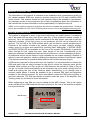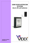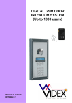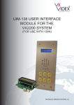
1
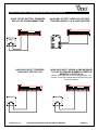
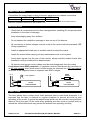
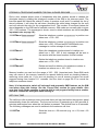
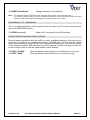
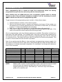
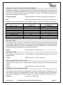
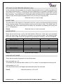
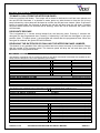
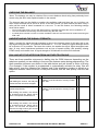
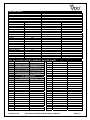
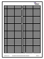
GSM DOOR INTERCOM SYSTEM (Vandal Resistant) ` Example panel only TECHNICAL MANUAL EDITION 2.0.0 PAGE 2 of 36 VR GSM DOOR INTERCOM TECHNICAL MANUAL VER2.0.0 CONTENTS Manual introduction System introduction Precautionary advice System components Intercom module Expansion button modules VX800 Codelock Door panel mounting frames Power supply Wiring diagrams Accessories wiring guide Cable guide Installation overview Panel care Testing, power up and reset Programming Programming by text message Programming by dial in System operation User commands Checking the balance of a Pay As You Go SIM Understanding the signal strength test Dial in priority Call button record keeping table Dial in access control record keeping table Understanding the beeps Troubleshooting guide Conformance information Software updates PAGE 3 of 36 VR GSM DOOR INTERCOM TECHNICAL MANUAL PAGE 4 4 5 6 – 12 6–7 8 9 - 11 12 12 13 14 15 15 15 16 17 – 26 17 – 23 24 – 26 27 - 28 27 28 28 28 29 29 - 30 31 32 33 34 VER2.0.0 MANUAL INTRODUCTION The information in this manual is intended as an installation and commissioning guide for the Vandal resistant GSM door intercom systems using the Art.150 self contained GSM audio module. This manual should be read carefully before the installation commences. Any damage caused to the equipment due to faulty installations where the information in this manual has not been followed is not the responsibility of Videx Security Ltd. VIDEX run free training courses for engineers who have not installed this system before. Technical help is also available on 0191 224 3174 during office hours or via e-mail [email protected]. SYSTEM INTRODUCTION The system is designed to work on the same technology as mobile phones. It enables a call to be made from an entry point (Door, gate etc), to any telephone number (mobile or land line). Up to ten call buttons can be connected to the door panel, each able to call two telephone numbers (If the first is busy or not answered, the call can be diverted to the second). The Art.150 is the GSM module which can be fitted to vandal resistant panel. Features of the module include a dry contact relay output, an open collector auxiliary output, push to exit input and switched 0V auxiliary input. Additionally, a SPEAK, BUSY and DOOR OPEN LED are available on the front of the module (DDA facility) to guide the caller through the call, speak and door open stages of the call. Programming of the telephone numbers and additional features can be carried out via text messaging or dial in. An additional access control feature is also available on the system allowing a number of callers to open the gate/door simply by dialling the telephone number of the intercom panel (The intercom panel will not answer these calls but will activate the relay output). A SIM card is required for this product but not supplied. It is recommended to choose the SIM card which has the best coverage for the area in which the intercom panel will be installed. Both contract and ‘Pay as you go’ SIM cards can be used but if using a ‘Pay as you go’ we would recommend setting up an automatic top up to avoid running short on credit and loosing the use of the intercom panel. Alternatively if you already have a contract mobile phone it should be possible to get a second SIM card and telephone number on the existing account. For more information contact the SIM card providers or visit their web sites. The SIM card holder is located under the cover of the amplifier. See Testing, power up and reset for more information. When registering a new SIM you may be asked for the IMEI number. This is the unique serial number of the GSM intercom and can be found on the rear of the module as shown in the picture below:- IMEI Number PAGE 4 of 36 VR GSM DOOR INTERCOM TECHNICAL MANUAL VER2.0.0 PRECAUTIONARY ADVICE o When mounting the GSM antenna, choose a location which is away from human interaction and away from the intercom panel. Route the GSM antenna cable from the intercom panel so that it is separate from the power supply cables and microphone wire. o Always ensure the power is off to the intercom panel before inserting or removing the SIM card. o New SIM cards will need registering before they can be used. Full details of how this is done can normally be found in the SIM card pack. It will normally require that the SIM card is inserted into a mobile phone, a number dialled and instructions followed. While the SIM is in the mobile phone it would be a good time to disable any PIN codes, call diverts, ring back and disable features such as voicemail and text alerts. Details of how to do this can be found on the SIM card provider’s web site or by calling their customer services. Please use one of the following SIM card providers (Vodafone, TMobile, O2 or Orange). We do not recommend using 3 at this present time. o To be able to receive text messages from the intercom panel, the SIM card will require an SMS service centre number. This is normally preinstalled on new SIM cards but if you are having trouble receiving SMS messages you will need to confirm this by inserting the SIM card into a telephone and using the telephones menu options to check it. If a number is not programmed then it should be programmed while in the telephone (The number can be obtained from the service provider). o Voicemail and text alerts must be switched off on the SIM card when using the dial in to release the door/gate feature. For Vodafone and O2 this can be done while the SIM card is in the intercom panel. For Orange and T-Mobile the SIM card must be remove and put into a mobile phone. o When storing the intercom panel’s telephone number in your own mobile phone avoid using an obvious name such as ‘Front Door, or ‘My Gate’ as this would make it easy to decipher if your phone was lost or stolen. o The PIN request feature must be disabled on the SIM card before using it in the Intercom panel. It is likely on a new SIM card that it will not be enabled but if it is, it will prevent the system from working at all. o This product may not be suitable for installation in hospitals, health care facilities or in the presence of flammable gases or liquids. Seek advice and authorisation before installing this product in these locations. IMPORTANT NOTE ABOUT SIM CARD When using a pay monthly SIM card you must ask the service provider to put a spend limit on the account (Vodafone call this service ‘spend checker’). This is to safeguard against possible problems which could result in a large phone bill at the end of the month. All providers offer this service. You will need to either ring them or e-mail them to set this up. Automatic top ups should also have a monthly limit. PAGE 5 of 36 VR GSM DOOR INTERCOM TECHNICAL MANUAL VER2.0.0 SYSTEM COMPONENTS A system comprises of an intercom panel (which includes the Art.150 module), power supply, SIM card and antenna. The intercom panel can be customised to the installation requirements by including proximity access control, coded access or bioaccess and also including the correct number of call buttons. ART.150 MODULE The intercom panel can be a standard or custom size vandal resistant panel or could be made up as a modular vandal resistant panel using modules from the VR4K range. Either way, it will include the Art.150 GSM module. The GSM module (pictured left) includes all the GSM communication electronics, SIM card (Supplied seperately) and connections. A green open LED, a red busy LED and a yellow speak LED are fitted to the front of this module to guide the caller thought the call process. VR4K GSM SPEAKER MODULES (Includes the Art.150) VR4KGSM-0 VR4KGSM-1 VR4KGSM-2 VR4KGSM-3 JUMPER SETTINGS There are 2 jumpers located on the back of the module. JP1 & JP2 can be used to alter the volume from the Door Intercom speaker (In addition to the volume control via programming codes during a call). SPEAKER VOLUME JP1 A JP2 A B B PAGE 6 of 36 JP2 B A B A JP3 B B A A GAIN (dB) 6 12 18 23.5 VR GSM DOOR INTERCOM TECHNICAL MANUAL VER2.0.0 CONNECTION +12V 0V NC NO C AI PE a b c d e C1 C2 AO DESCRIPTION 12Vdc input to power the module Ground connection Normally closed connection of dry contact relay Relay contacts: 3A@24Vdc Normally open connection of dry contact relay 3A@120Vac Common connection of dry contact relay Auxiliary input (Between AI & C1 triggers AO, Between AI & C2 sends an SMS to the number stored in memory location 020 Exit button input (Between PE & C1) Triggers relay for programmed time. a – e are switched 0V inputs from the call buttons. The common side of the call buttons connects to either C1 or C2 (C1 with a-e for buttons 1-5, C2 with a-e for buttons 6-10) Common 1 for call buttons 1-5 & PTE & AI(AO Output trigger) Common 2 for call buttons 6-10 & AI(SMS sent) 0V auxiliary output (Open collector) Max. 150mA ANTENNA The GSM antenna connects to the SMA female bulkhead on the rear of the module. A GSM antenna with a SMA male connector should be used. An antenna is supplied along with an L mounting bracket. Other types of GSM antenna can also be used. Note: An antenna must always be connected. Note: Always route the GSM cable away from the microphone wires and the power supply wires to avoid interference on the speech channels. SIM CARD The GSM Intercom is supplied without a SIM card. T0 insert a SIM card, remove the cover from the Art.150, insert a SIM card and replace the lid. Remember to only insert/remove the SIM card when all power to the unit is removed, the SIM card can be damaged if inserted/removed while the power is on. Also remember that the SIM may need setting up prior to inserting into the intercom as stated earlier in this manual. PAGE 7 of 36 VR GSM DOOR INTERCOM TECHNICAL MANUAL VER2.0.0 EXTENSION BUTTON MODULES The GSM intercom module will accept up to ten call buttons. Any of the vandal resistant 4000 series button modules can be used as shown below. VR4KBM-4 VR4KBM-5 VR4KBM-6 VR4KBM-7 VR4KBM-8 VR4KBM-9 CALL BUTTON WIRING PAGE 8 of 36 VR GSM DOOR INTERCOM TECHNICAL MANUAL VER2.0.0 CODELOCK MODULE (VR4KCLM, 800CL) The codelock includes three relay outputs (Only 2 on the 800CL), two push to exit button inputs and operates from a 12-24V ac/dc power supply. Up to 2 unique codes can be programmed, each in the range of 4-8 digits. Relay time can be programmed from 01 – 99 seconds or set to latching mode with a relay time of 00 (To latch, type in the code followed by Enter, to unlatch, type in the code followed by clear). Connection + C1 NO1 NC1 C2 NO2 NC2 C3 NO3 NC3 SW1 SW2 PAGE 9 of 36 Art.4800 Connections Function 12-24V ac/dc power input 0V power input Common connection of relay 1 (Dry contact) Normally open connection of relay 1 (Dry contact) Normally closed connection of relay 1 (Dry contact) Common connection of relay 2 (Dry contact) Normally open connection of relay 2 (Dry contact) Normally closed connection of relay 2 (Dry contact) Common connection of relay 3 (Dry contact) Normally open connection of relay 3 (Dry contact) Normally closed connection of relay 3 (Dry contact) Push to exit input for relay 1 (Triggered by 0V) Push to exit input for relay 2 (Triggered by 0V) VR GSM DOOR INTERCOM TECHNICAL MANUAL VER2.0.0 ART.4800 CODELOCK INITIAL PROGRAMMING All programming is carried out using the codelock keypad. The programming menu is protected by an engineer’s code. The factory default engineers code is 111111 (6x1). This code can be changed to any four to eight digit code during the program but must be different to the codes used to gain entry. Follow the flow chart to setup the system:Enter the engineers code. 111111 Then press enter The red LED will illuminate to acknowledge programming mode. If the red LED does not illuminate check the master code is correct. If the master code may have been changed from the factory default and you do not know what it is then follow the factory default procedure on the following page. Enter a new engineers code or enter the same engineers code again followed by enter This code can be from 4 – 8 digits and will not activate a relay. It can only be used to enter programming mode. Note this new code in the box provided on the next page. It will be needed to re-program the codes in the future. Enter the access code for relay 1 and then press enter This code will be used to open the door/gate (Relay 1). The code can be from 4 – 8 digits long and must be different from the engineer’s code. Enter a two digit relay 1 time from 00 – 99 and then press enter This is the time the relay 1 will energise for. 00 will latch the relay when the code is entered and require the code followed by clear to unlatch. NO More codes? YES Enter the access code for relay 2 and then press enter This code will be used to open the door/gate (Relay 2). The code can be from 4 – 8 digits long and must be different from the engineer’s code. Enter a two digit relay 2 time from 00 – 99 and then press enter This is the time the relay 2 will energise for. 00 will latch the relay when the code is entered and require the code followed by clear to unlatch. NO More codes? YES Enter the access code for relay 3 and then press enter This code will be used to open the door/gate (Relay 3). The code can be from 4 – 8 digits long and must be different from the engineer’s code. Enter a two digit relay 3 time from 00 – 99 and then press enter This is the time the relay 3 will energise for. 00 will latch the relay when the code is entered and require the code followed by clear to unlatch. Press enter twice PAGE 10 of 36 The red LED will go off to confirm the exit from programming mode. VR GSM DOOR INTERCOM TECHNICAL MANUAL VER2.0.0 ART.4800 CODELOCK REPROGRAMMING GUIDE Engineers code Relay 1 code Relay 2 code Relay 3 code Enter the engineer’s code RED Light will illuminate * Press Enter Re-Enter the engineer’s code Alternatively enter a new engineer’s code (4-8 digits) Relay 1 Time Relay 2 Time Relay 3 Time Press Enter Enter relay code Relay code (4 – 8 digits) operates the door or gate. ** Press Enter Enter relay time Two digits (01 – 99 Sec or 00 for remain open) Press Enter More doors? NO Press Enter twice to exit programming RED Light will switch off YES Repeat steps for relay 2 & relay 3 Notes: * If the red light does not illuminate, the engineers code is incorrect. Follow the factory default procedure below. ** On the first loop of the flow chart its relay 1, second loop is relay 2. FACTORY DEFAULT PROCEDURE Step 1 Remove the power from the keypad Step 2 Press and hold the enter button while re-powering the keypad Step 3 Release the enter button. The factory engineer’s code is restored to 111111 (6 x 1) PAGE 11 of 36 VR GSM DOOR INTERCOM TECHNICAL MANUAL VER2.0.0 DOOR PANEL MOUNTING FRAMES (VR4K SERIES) Both surface and flush mounting frames are available. The size of the frame will depend on the number of modules that make up the door panel. The last digit of the frame code indicates the number of modules it will take. Frames are available in gun metal gray finish, chrome finish (Suffix \C to the frame code) or gold finish (Suffix \G to the frame code). Flush frames: Surface frames: POWER SUPPLY The GSM intercom panel is designed to work with power supplies of 12-14Vdc. The power supply should be capable of supplying a constant current of no less than 1 amp (If the system is to work with failsafe lock releases or magnetic locks we would recommend a minimum of 2 amps). The following Videx power supplies can be used:Art.324 Art.521B SP29 SP28 12Vdc 2A Switched mode DIN box PSU 13.5Vdc 1A DIN box PSU 13.8Vdc 2A boxed PSU with battery back up facility 13.8Vdc 3A boxed PSU with battery back up facility PAGE 12 of 36 VR GSM DOOR INTERCOM TECHNICAL MANUAL VER2.0.0 WIRING DIAGRAMS PAGE 13 of 36 VR GSM DOOR INTERCOM TECHNICAL MANUAL VER2.0.0 PUSH TO EXIT BUTTON AND AUXILIARY INPUTS/OUTPUTS PUSH TO EXIT BUTTON, TRIGGERS RELAY FOR PROGRAMMED TIME AUXILIARY INPUT, TRIGGERS AUXILIARY OUTPUT (AO) AUXILIARY OUTPUT (OPEN COLLECTOR), TRIGGERS WHEN C1 & AI ARE SHORTED AUXILIARY INPUT, SENDS A SMS MESSAGE TO THE TELEPHONE NUMBER STORED IN MEMORY LOCATION 020 (NOTE: Once triggered, it can’t be triggered again for 4 minutes. This avoids multiple SMS messages being sent for the same alarm) PAGE 14 of 36 VR GSM DOOR INTERCOM TECHNICAL MANUAL VER2.0.0 CABLE SIZE GUIDE Connections for power supply output to intercom panel and lock release connections. 20m 50m 100m 0.5mm² 1.0mm² 1.5mm² Connections The power supply should be located as close to the intercom panel as possible for best performance. Maximum acceptable resistance for above cables = 3Ω INSTALLATION - Check that all components are free from damage before installing (Do not proceed with installation in the event of damage). - Keep all packaging away from children. - Do not obstruct the ventilation openings or slots on any of the devices. - All connections to mains voltages must be made to the current national standards (IEE Wiring regulations) - Install an appropriate fused spur or isolation switch to isolate the mains. - Isolate the mains before carrying out any maintenance work on the system. - Avoid water ingress into the rear of the module, always seal the module frame after installation using a suitable silicon based sealant. - All intercom and access control cables must be routed separately from the mains. Lock release back EMF protection : A capacitor must be fitted across the terminals on an AC lock release and a diode must be fitted across the terminals on a DC lock release as shown in the diagrams below to suppress back EMF voltages. ~~ 0.1uF capacitor - + - 12V AC LOCK RELEASE DIODE 1N4002 + 12V DC LOCK RELEASE PANEL CARE The door panels facia is either mirror finish stainless steel or matt finish aluminium. It is important that the facia is cleaned on regular occasions to prevent dirt build up and tarnishing of the metal. A general household metal polish can be used but care should be taken to follow the grain of the metal when polishing and also avoid any polish build up around the call buttons which may prevent the buttons from operating correctly. PAGE 15 of 36 VR GSM DOOR INTERCOM TECHNICAL MANUAL VER2.0.0 TESTING, POWER UP AND RESET After connecting the power supply, antenna, lock output and auxiliary devices as shown in this manual and before powering up, a SIM card must be installed. The SIM holder can be found inside the Art.150 modul. A SIM card from any supplier can be used. Simply push the SIM holder in the direction of ‘OPEN’ and then lift. Insert the SIM card (It will only fit one way) and then push back down and into the ‘LOCK’ position. IMPORTANT: If this is a new SIM card it may require initialising before inserting into the intercom panel. - Check all the connections have been made correctly and then power up the system. The GSM intercom requires approximately 30 seconds too initialise properly. We recommend not sending SMS messages or pressing buttons during this time. From power up; two short beeps will be heard and then following a short delay of approximately 15 seconds, a further short beep will be heard. After approximately another 15 seconds another short beep will be heard. The module is now fully initialised (Note: If you here a different combination of beeps in place of the last short single beep then you can find the meaning of these beeps towards the back of this manual. Once initialised, you can begin programming. Power up initialisation sequence 2 short beeps (RED LED Illuminates) Approx. 15 seconds delay 1 short beep (RED LED Goes out) Approx. 15 seconds delay One short beep System is ready RESET TO FACTORY DEFAULTS There are two reset modes available. The first will reset the master code only and the second will reset everything and clear all stored call button telephone numbers. RESET THE MASTER CODE TO 1111 1. Power down the intercom panel 2. Put a short across C1 & PTE 3. Power up, 2 beeps will be heard followed by a delay and then a further beep. 4. Remove the short after the 3rd beep. 5. The master code is now reset to 1111 FULL RESET 1. Power down the intercom panel 2. Put a short across C2 & PTE 3. Power up, 2 beeps will be heard followed by a delay and then a further 3 beeps. 4. Remove the short after the 5th beep. 5. All settings are returned to factory defaults PAGE 16 of 36 VR GSM DOOR INTERCOM TECHNICAL MANUAL VER2.0.0 PROGRAMMING Programming can be carried out either by text message or by dialling into the intercom panel (Certain programming features can only be setup by text message). IMPORTANT NOTE: When you are required to use “ in a text message it is very important to use the correct symbol and not for example ‘ (Or two ‘ single apostrophes side by side which you will see look the same but will be interoperated differently by the SMS intercom panel). PROGRAMMING BY TEXT MESSAGE Programming by text message is the simplest way to customise the settings of the intercom panel and add or delete telephone numbers. Simply send texts in the format below to the telephone number of the SIM within the intercom panel:<4 DIGIT CODE><3 DIGIT FUNCTION CODE><OPTIONAL DATA><OPTIONAL ?> 4 DIGIT CODE: The code prevents unauthorised access to the programmable features of the system. The code must be four digits long but can be any combination using digits 0 – 9. The default code is 1111 and will be used for all examples in this manual. 3 DIGIT FUNCTION CODE: The 3 digit function code identifies the programmable feature to be changed. The code must be in capital letters. The table below lists the available codes. DESCRIPTION Store a telephone no. Set call time Set relay time Set auxiliary out time Set auxiliary out mode Keep connection facility Divert to second no. time Enable/disable divert Check GSM signal strength Check software version Dial a number Store SMS message for C2-AI Change 4 digit code Initiate a special command Trigger the relay Trigger the auxiliary output Store balance check dial string Check credit balance Latch the relay Unlatch the relay Latch the auxiliary output Unlatch the auxiliary output OPTIONAL DATA: PAGE 17 of 36 CODE STN SPT RLT AOT AOM NOD DIT DIV SIG VER DLE SMS CDE PRG RLY AUX SDL BAL RLA RUL ALA AUL EXAMPLE 1111STNnnn”01912243174” 1111SPTnn 1111RLTnn 1111AOTnn 1111AOMnn 1111NODnn 1111DITnn 1111DIVnm 1111SIG? 1111VER? 1111DLE”123” 1111SMS”HouseAlarm” 1111CDE1234 1111PRG(command) 1111RLY 1111AUX 1111SDL”*#1345#” 1111BAL? 1111RLA 1111RUL 1111ALA 1111AUL SETTINGS nnn = 001-250 nn = 01 - 12 nn = 00 - 99 nn = 00 - 99 nn = 00 or 01 nn = 01 - 99 nn = 01 - 99 n = 0-9 m = 0-1 N/A N/A N/A N/A Any 4 digits AT commands N/A N/A N/A N/A N/A N/A N/A N/A DEFAULT N/A 02 (40s) 05 (5s) 05 (5s) 01 30 (30days) 15 (15s) m=0 N/A N/A N/A AUX TRIG 1111 N/A N/A N/A N/A N/A N/A N/A N/A N/A PAGE 19-20 20 21 21 21-22 22 22 22-23 28-29 28 23 23 22 24 28 28 24 28-29 28 28 28 28 The optional data will vary depending on the command used. It may be a telephone number, a time setting or may not be used at all. For more information see the command settings below. VR GSM DOOR INTERCOM TECHNICAL MANUAL VER2.0.0 Most of the commands support the ? feature. When this is added to the end of the text message, a confirmation text message will be sent back to the sender indicating the new data has been received and stored. OPTIONAL ?: When sending text messages there may be a delay from when you send the message to when it is received by the intercom panel depending on how congested the network is. If you are at the door panel when sending the message you will here a single beep from the intercom panel to indicate it has receive the message. STORING A CALL BUTTON TELEPHONE NUMBER Telephone numbers can be stored for the ten available call buttons. Each call button can call up to two telephone numbers (If the first is busy or not answered in a certain time it can call the second number if the divert facility is setup). The messages to store/check numbers are as follows (See important note on page 18):1111STNnnn”yyyyyyyyyyy” Store the telephone number yyyyyyyyyyy in position nnn 1111STNnnn”yyyyyyyyyyy”? Store the telephone number yyyyyyyyyyy in position nnn and send a confirmation text message to confirm storage of new number. 1111STNnnn? Query the telephone number stored in location nnn. A text message will be sent to the sender with the stored number for that location. 1111STNnnn”” Delete the telephone number stored in location nnn. 1111STNnnn””? Delete the telephone number stored in location nnn. A text message will be sent to the sender with the delete confirmation for that location. nnn can be found using the following table. The telephone number y can be a maximum of 19 digits. Call Button Memory location (nnn) of Memory location (nnn) of first number called divert to number to call Button 1 (C1 & a) 001 011 Button 2 (C1 & b) 002 012 Button 3 (C1 & c) 003 013 Button 4 (C1 & d) 004 014 Button 5 (C1 & e) 005 015 Button 6 (C2 & a) 006 016 Button 7 (C2 & b) 007 017 Button 8 (C2 & c) 008 018 Button 9 (C2 & d) 009 019 Button 10 (C2 & e) 010 020 Use the chart on page 26 to record the telephone numbers stored. PAGE 18 of 36 VR GSM DOOR INTERCOM TECHNICAL MANUAL VER2.0.0 STORING A TELEPHONE NUMBER FOR DIAL IN DOOR RELEASE Dial in door release allows users of telephones with their number stored to release the door/gate simply by dialling the telephone number of the SIM in the intercom panel. The intercom panel will check the callers ID when it receives a call and if it matches the list of stored numbers, it will clear the call down (Avoiding the caller being charged for the call) and will activate the relay for the programmed time. The number of numbers thatcan be stored depends on the SIM card’s available memory. SIM cards are normally able to store 100 – 250 numbers. The messages to check, store or delete numbers are as follows (See important note on page 18):1111STNnnn”yyyyyyyyyyy” Store the telephone number yyyyyyyyyyy in position nnn where nnn = 100 - 250 1111STNnnn”yyyyyyyyyyy”? Store the telephone number yyyyyyyyyyy in position nnn where nnn =100 - 250and send a confirmation text message to confirm storage of new number. 1111STNnnn? Query the telephone number stored in location nnn where nnn = 100 - 250. A text message will be sent to the sender with the stored number for that location. 1111STNnnn# Delete the telephone number stored in location nnn where nnn = 100 - 250. 1111STNnnn#? Delete and confirm deletion of a telephone number in location nnn where nnn = 100 - 250. Memory location nnn can be in the range of 100 – 250. (Important note: Some SIM cards may use some of the memory locations for special features such as checking balance, retrieving voice mails etc. If you are not planning to use all memory location we would suggest storing from location 111 onwards. Use the chart on page 26-27 to record the telephone numbers stored. Note: It is important to switch off voicemail and automatic SMS features on the SIM card when using this feature. See the ‘Forced Dial’ section for more details. Also note that it will not be possible to use the dial in and program facility from a number stored to release the door/gate when dialling in. SET CALL TIME The call time is the maximum time in seconds that a call can last before the intercom panel automatically clears the call down. The time can be from 20 seconds up to 240 seconds (4 minutes) and begins from when the call button is pressed. The default time is 40 seconds. The following messages are used to set/check the maximum call time. 1111SPTnn PAGE 19 of 36 Store the time nn x 20 seconds (e.g. nn = 03, time = 60 seconds. VR GSM DOOR INTERCOM TECHNICAL MANUAL VER2.0.0 1111SPTnn? Store the time nn x 20 seconds (e.g. nn = 02, time = 40 seconds. Also send a confirmation text back to the sender. 1111SPT? Query the current stored time. A text message will be sent to the sender showing the stored time. (Remember to multiple the number in the received text by 20 seconds) SET RELAY TIME The relay time can be from 01 – 99 seconds or latching (Set the relay time to 00 for latched mode. In latch mode, the relay will stay energised until the command is send again). 1111RLTnn Store the time nn = time in seconds. 1111RLTnn? Store the time nn = time in seconds. Also send a confirmation text back to the sender. 1111RLT? Query the current stored time. A text message will be sent to the sender showing the stored time. SET AO (AUXILIARY OUTPUT) TIME (FOR AOM = 01 ONLY) The AO time can be from 01 – 99 seconds or latching (Set the AO time to 00 for latched mode). 1111AOTnn Store the time nn = time in seconds. 1111AOTnn? Store the time nn = time in seconds. Also send a confirmation text back to the sender. 1111AOT? Query the current stored time. A text message will be sent to the sender showing the stored time. SET AO (AUXILIARY OUTPUT) MODE There are two mode of operation for the AO terminal:User activated: nn = 01 To activate the AO terminal either short AI to C1 or press 6 on the telephone during a call. Call activated: nn = 00 AO will activate when a call begins and deactivate when the call ends. 1111AOMnn Store the mode nn = 01 or 00. 1111AOMnn? Store the mode nn = 01 or 00. Also send a confirmation text back to the sender. PAGE 20 of 36 VR GSM DOOR INTERCOM TECHNICAL MANUAL VER2.0.0 1111AOM? Query the current stored mode. A text message will be sent to the sender showing the stored mode. CHANGING THE FOUR DIGIT CODE The four digit code can be any combination of numbers 0-9 but must be 4 digits long. The code allows access to the programming menu in dial in mode and must be used when sending text messages to the intercom panel. The following message changes the code:1111CDEnnnn nnnn = new 4 digit code SET DAYS TO WAIT BEFORE MAKING A CALL In the event the intercom panel is not used for long periods of time it could be possible that the network disconnects it. To prevent this from happening it is possible to program a time period (From 01 – 99 days) to wait before the intercom panel makes a short call to refresh the connection. This time period is reset after each call made on the system and will only happen if the full time period elapses without any incoming or outgoing calls. 1111NODnn Store the time nn = time in days. 1111NODnn? Store the time nn = time in days. Also send a confirmation text back to the sender. 1111NOD? Query the current stored time. A text message will be sent to the sender showing the stored time. DIVERT TIME The divert time is the number of seconds to wait for a call to be answered before diverting to the second number (The divert facility must be set for this to work). The default time is 15 seconds (The count down begins from when the call button is pressed, but is refreshed when the telephone begins to ring) and can be set to 01 – 99 seconds). 1111DITnn Store the time nn = time in seconds. 1111DITnn? Store the time nn = time in seconds. Also send a confirmation text back to the sender. 1111DIT? Query the current stored time. A text message will be sent to the sender showing the stored time. PAGE 21 of 36 VR GSM DOOR INTERCOM TECHNICAL MANUAL VER2.0.0 DIVERT SETUP Divert can be set for any or all of the call buttons. When set, if a call is not answered within the divert time, the call will be forwarded to the second number and the call time will be refreshed. The following table shows the value of nm used in the programming messages. Default is all diverts disabled (m=0). CALL BUTTON Button 1 (C1 & a) Button 2 (C1 & b) Button 3 (C1 & c) Button 4 (C1 & d) Button 5 (C1 & e) Button 6 (C2 & a) Button 7 (C2 & b) Button 8 (C2 & c) Button 9 (C2 & d) Button 10 (C2 & e) SET DIVERT 01 11 21 31 41 51 61 71 81 91 DISABLE DIVERT 00 10 20 30 40 50 60 70 80 90 n = Call Button number from 1 – 10 (0-9) m = Divert set (1) or divert not set (0) 1111DIVnm 1111DIVnm? Store the divert setting. Store the divert setting. A text message will be sent to the sender with the acknowledgment. FORCED DIAL A useful feature of the Intercom panel is its ability to call a number sent to it in a text message. This feature can be used when setting up the SIM card. For example, disabling the voicemail facility or disabling automatic SMS messages or missed calls. Any number up to 15 digits can be called and the call will last for a maximum of 40 seconds. The example below would switch off voicemail on a Vodafone SIM card. Substitute the Vodafone number for other service providers (See important note on page 18). 1111DLE”1210“ Dial 1210 for the intercom panel Other useful numbers which can be used with this feature are as follows. Please also check the service provider’s web sits for other useful codes. Vodafone Disable voicemail Disable text alerts 1210 #148# O2 1760 1760 NOTE: Disabling voicemail and text alerts is very important as there is no way to retrieve either of these services from an intercom panel. Disabling these features will also prevent the intercom panel switching to voicemail or sending a text when dialling in from another phone. STORE SMS AUXILIARY MESSAGE When C2 & AI are shorted on the intercom panel, a text message will be sent to the number stored in memory location 020. The text message can be customised using the following message(See important note on page 18) :PAGE 22 of 36 VR GSM DOOR INTERCOM TECHNICAL MANUAL VER2.0.0 Change message to HouseAlarm 1111SMS”HouseAlarm” Note: The message can be a maximum of 20 characters long and can not include spaces or “. The memory location used to store the telephone where the text will be send is also the same memory location used for the divert telephone number for button 10 (i.e. 020). PROGRAM BY ‘AT’ COMMANDS This is an advanced feature of the system which can allow an AT format command to be sent to the OEM GSM module. 1111PRG(command) Send an AT command to the OEM module STORE CREDIT BALANCE CHECK STRING Several network providers offer the facility to check available balance on their pay as you go tariffs. For example, on Vodafone the string is *#1345# and on O2 the string is *#10#. Other networks may also have this feature. Because the intercom will not know the details of the network provider’s SIM card which you have inserted it will be necessary to store the correct string in order to use the credit balance check features. 1111SDL”*#1345#” 1111SDL”*#10#” PAGE 23 of 36 Store the balance check string for a Vodafone pay as you go. Store the balance check string for an O2 pay as you go. VR GSM DOOR INTERCOM TECHNICAL MANUAL VER2.0.0 PROGRAMMING BY DIAL IN Note: programming dial in cannot be used from telephones which are already programmed to open the door when they dial the intercom panel. When dialling into the GSM intercom from a telephone number which is already stored as one of the call button telephone numbers it will be necessary be press to switch from call mode to programming mode. To gain access to the programming menu via dial in, follows these steps:1. Call the telephone number of the intercom panel. 2. Wait for the intercom panel to answer and signal by two beeps (If the number you are dialling from is already programmed as a call button number then you will need to press before proceeding to the next step). 3. Enter the four digit code listening for a confirmation beep after each digit. 4. If the code is correct, you will here two beeps to indicate programming mode. If the code is incorrect the call will end and the line will go dead. Once in programming mode, the following options are available. Remember to listen for a beep after each digit entered. This indicates that it has been received and understood by the intercom panel. The intercom panel will stay in programming mode until the call ends or a timeout occurs. The timeout will occur after 30 seconds if no buttons are pressed. This is reset to 30 seconds each time a button is pressed. Note: At any point press the # key to clear and begin a programming sequence again. # is also used to confirm and store a new value. After pressing #, two beeps will be heard from the telephone to indicate successful completion of a command, four beeps will indicate an error in the command. The following table outlines the available programming codes. These are explained in detail on the following pages. DESCRIPTION Store a telephone no. Storing a divert telephone no. Set call duration time Set relay time Set auxiliary out time Keep connection facility Divert to second no. time Set auxiliary out mode Enable/disable divert Change 4 digit code NOTE: PAGE 24 of 36 CODE 01-10 11-29 50 51 52 55 56 57 58 59 EXAMPLE nn01912243174# nn01912243174# 50nn# 51nn# 52nn# 55nn# 56nn# 57nn# 58nm# 59nnnn# SETTINGS nn = 01-10 nn = 11-20 nn = 01-12 nn = 00 - 99 nn = 00 - 99 nn = 01 - 99 nn = 01 - 99 nn = 01 or 00 n = 0-9 m = 0-1 nnnn= 4 digits DEFAULT N/A N/A 02 05 (5s) 05 (5s) 10 (10days) 15 (15s) 01 m=0 1111 PAGE 26 26 26 26 26 27 27 27 27 26 While in dial in mode it is also possible to start a call with the intercom panel which will open the speech and also allow the user functions such as triggering the relay to work. After dialling in, enter the 4 digit code and the press to start the call. VR GSM DOOR INTERCOM TECHNICAL MANUAL VER2.0.0 STORING A CALL BUTTON TELEPHONE NUMBER Telephone numbers can be stored for the ten available call buttons. Each call button can call up to two telephone numbers (If the first is busy or not answered in a certain time it can call the second number if the divert facility is setup). The following programming sequence stores telephone numbers. nnyyyyyyyyyyy# Store the telephone number yyyyyyyyyyy in position nn nn# Delete the telephone number yyyyyyyyyyy in position nn nn can be found using the table. The telephone number y can be a maximum of 19 digits. Call Button Button 1 (C1 & a) Button 2 (C1 & b) Button 3 (C1 & c) Button 4 (C1 & d) Button 5 (C1 & e) Button 6 (C2 & a) Button 7 (C2 & b) Button 8 (C2 & c) Button 9 (C2 & d) Button 10 (C2 & e) Memory location (nn) of first number called 01 02 03 04 05 06 07 08 09 10 Memory location (nn) of divert to number to call 11 12 13 14 15 16 17 18 19 20 Use the chart on page 26 to record the telephone numbers stored. SET CALL TIME The call time is the maximum time in seconds that a call can last before the intercom panel automatically clears the call down. The time can be from 20 seconds up to 240 seconds (4 minutes) and begins from when the telephone rings. The default time is 40 seconds. The following programming sequence stores a new call time. 50nn# Store the time nn x 20 seconds (e.g. nn = 3, time = 60 seconds.) SET RELAY TIME The relay time can be from 01 – 99 seconds or latching (Set the relay time to 00 for latched mode). 51nn# Store the time nn = time in seconds. SET AO (AUXILIARY OUTPUT) TIME The AO time can be from 01 – 99 seconds or latching (Set the AO time to 00 for latched mode). 52nn# Store the time nn = time in seconds. CHANGING THE FOUR DIGIT CODE The four digit code can be any combination of numbers 0-9 but must be 4 digits long. The code allows access to the programming menu in dial in mode and must be used when sending text messages to the intercom panel. The following message changes the code:59nnnn# PAGE 25 of 36 nnnn = new 4 digit code VR GSM DOOR INTERCOM TECHNICAL MANUAL VER2.0.0 SET DAYS TO WAIT BEFORE MAKING A CALL In the event the intercom panel is not used for long periods of time it could be possible that the network disconnects it. To prevent this from happening it is possible to program a time period (From 01 – 99 days) to wait before the intercom panel makes a short call to refresh the connection. This time period is reset after each call made on the system and will only happen if the full time period elapses without any incoming or outgoing calls. Store the time nn = time in days. 55nn# DIVERT TIME The divert time is the number of seconds to wait for a call to be answered before diverting to the second number (The divert facility must be set for this to work). The default time is 15 seconds (The count down begins from when the call button is pressed) and can be set to 01 – 99 seconds). Store the time nn = time in seconds. 56nn# DIVERT SETUP Divert can be set for any or all of the call buttons. When set, if the call is not answered within the divert time, the call will be diverted to the second number. The following table shows the value of nn used in the programming messages. Default is, all diverts disabled. CALL BUTTON Button 1 (C1 & a) Button 2 (C1 & b) Button 3 (C1 & c) Button 4 (C1 & d) Button 5 (C1 & e) Button 6 (C2 & a) Button 7 (C2 & b) Button 8 (C2 & c) Button 9 (C2 & d) Button 10 (C2 & e) SET DIVERT 01 11 21 31 41 51 61 71 81 91 DISABLE DIVERT 00 10 20 30 40 50 60 70 80 90 Store the divert setting. 58nn# AUXILIARY OUT MODE There are two mode of operation for the AO terminal:User activated: nn = 01 To activate the AO terminal either short AI to C1 or press 6 on the telephone during a call. Call activated: nn = 00 AO will activate when a call begins and deactivate when the call ends. 57nn# PAGE 26 of 36 Store the mode nn = 01 or 00. VR GSM DOOR INTERCOM TECHNICAL MANUAL VER2.0.0 SYSTEM OPERATION TO MAKE A CALL FROM THE INTERCOM PANEL Press the required call button. Two beeps will be heard to indicate the call has been placed and the red LED will illuminate. If a mistake is made, press any other button to clear the call (A long beep followed by a short beep will be heard to confirm the call has been cleared. (Note: If the same button is pressed after five seconds of placing the call this will also clear the call down. Pressing the same button before five seconds will do nothing). When the call is answered, the yellow LED will illuminate. DOOR/GATE RELEASE This is signalled by 1 second interval beeps from the intercom panel. Pressing 3 releases the door/gate for the programmed time. Pressing 1 followed by 0 will latch the door/gate in the open position (Note: To unlatch press 3, the door/gate will unlatch after the programmed time. When the door/gate is released, the green LED will illuminate. RELEASING THE GATE/DOOR BY DIALLING THE INTERCOM PANEL NUMBER This feature is only possible if the caller’s number has been stored correctly for this feature. Simply dial the number of the intercom panel. The intercom panel will drop the call and then open the gate/door for the programmed time. USER COMMANDS The following commands can be carried out during a call: (Note: Successful commands are signalled by two beeps from the telephone, errors are signalled by four beeps). 2nd KEY TO PRESS FUNCTION 1st KEY TO PRESS LATCH RELAY (UNLATCH BY PRESSING 3) 1 0 RELEASE THE DOOR OR GATE 3 N/A ACTIVATE THE AUXILIARY OUTPUT 6 N/A END A CALL 8 N/A ADJUST DOOR SPEECH VOLUME 4 0-9 (0=Lowest, 9 = Highest) ADJUST PHONE SPEECH VOLUME 7 0-9 (0-Lowest, 9 = Highest) ENTER PROGRAMMING MODE DURING A CALL The following text messages can be sent while in standby (Examples show code as 1111): FUNCTION MESSAGE TO SEND CHECK THE SIGNAL STRENGTH 1111SIG? CHECK THE AVAILABLE BALANCE* 1111BAL? CHECK THE SOFTWARE VERSION 1111VER? RELEASE THE DOOR/GATE 1111RLY? (? Optional, send if a confirmation is required) ACTIVATE THE AUXILIARY OUTPUT 1111AUX? (? Optional, send if a confirmation is required) LATCH THE RELAY 1111RLA? (? Optional, send if a confirmation is required) UNLATCH THE RELAY 1111RUL? (? Optional, send if a confirmation is required) LATCH THE AUXILIARY OUTPUT 1111ALA? (? Optional, send if a confirmation is required) UNLATCH THE AUXILIARY OUTPUT 1111AUL? (? Optional, send if a confirmation is required) PAGE 27 of 36 VR GSM DOOR INTERCOM TECHNICAL MANUAL VER2.0.0 CHECKING THE BALANCE *Note: The balance can only be checked if the correct balance check string has previously been stored using the SDL code explained earlier in the manual. The intercom also has the facility to monitor the available credit and then text you to inform you when it has fell below £5.00, €5.00 or $5.00. It will then remind you with another text after every 5 calls until the credit is either increased or it runs out. To use this feature, the following settings must first be made:o o o You must be using a Pay AS You GO SIM card from a provider that offers this service (Vodafone, O2) The correct balance check string must be stored using the SDL code. A mobile phone number in which to receive the balance low text must be stored in location 020 using the STN code. UNDERSTANDING THE SIGNAL STRENGTH When a request for signal strength message is sent to the intercom panel it will reply with a two digit signal strength code. The code will be between 0 – 31 or 99. Ideally the signal strength should be as close to 31 as possible. The lower the number, the weaker the signal. Signal strengths lower than 10 may cause operational problems such as loss of speech quality (and possibly missing DTMF tones) and network loss. A signal strength of 99 indicates it could not be detected. DIALLING INTO THE INTERCOM FROM ANOTHER TELEPHONE There are three possible outcomes to dialling into the GSM intercom depending on the telephone number you are dialling in from and the features setup during programming. The three possible outcomes are shown in the table below and are shown in order of priority (For example, if the number is programmed to automatically activate the relay, this will take priority over the following two options and if the telephone number is stored as a telephone number called from one of the push buttons, this will take priority over the last option. FUNCTION Dial in to open the door. After dialling the number, the relay will activate and the call will be dropped. Dial in to activate a call (Live speech, activate relay/AUXO) REQUIREMENT The telephone number of the telephone dialling in must be stored in memory location 100 - 250 PRIORITY 1st The telephone number of the telephone dialling in must be stored in memory location 001 - 020 2nd If neither of the two requirements above are met. 3rd After dialling the number, the call will be answered and two beeps will be heard. The speech will then be live. Dial in to enter programming mode. After dialling the number, the call will be answered and two beeps will be heard. You will then be required to enter the four digit code to gain access to the programming menu. PAGE 28 of 36 VR GSM DOOR INTERCOM TECHNICAL MANUAL VER2.0.0 RECORD SHEET INTERCOM PANEL TELEPHONE No. IMEI NUMBER MASTER CODE BUTTON Button 1 Button 1 (Divert) Button 2 Button 2 (Divert) Button 3 Button 3 (Divert) Button 4 Button 4 (Divert) Button 5 Button 5 (Divert) Button 6 Button 6 (Divert) Button 7 Button 7 (Divert) Button 8 Button 8 (Divert) Button 9 Button 9 (Divert) Button 10 Button 10 (Divert) MEM. LOCATION 001 011 002 012 003 013 004 014 005 015 006 016 007 017 008 018 009 019 010 020 USER NAME TELEPHONE No. DIAL IN ACCESS CONTROL MEMORY RECORD SHEET Mem. 100 101 102 103 104 105 106 107 108 109 110 111 112 113 114 115 116 117 118 119 120 121 122 123 124 User Name Telephone No. ONLY USE THESE 10 MEMORY LOCATIONS AS A LAST RESORT. PREFERABLY, START AT MEMORY LOCATION 110 PAGE 29 of 36 Mem. 176 177 178 179 180 181 182 183 184 185 186 187 188 189 190 191 192 193 194 195 196 197 198 199 200 User Name VR GSM DOOR INTERCOM TECHNICAL MANUAL Telephone No. VER2.0.0 125 126 127 128 129 130 131 132 133 134 135 136 137 138 139 140 141 142 143 144 145 146 147 148 149 150 151 152 153 154 155 156 157 158 159 160 161 162 163 164 165 166 167 168 169 170 171 172 173 174 175 PAGE 30 of 36 201 202 203 204 205 206 207 208 209 210 211 212 213 214 215 216 217 218 219 220 221 222 223 224 225 226 227 228 229 230 231 232 233 234 235 236 237 238 239 240 241 242 243 244 245 246 247 248 249 250 VR GSM DOOR INTERCOM TECHNICAL MANUAL VER2.0.0 UNDERSTANDING THE BEEPS Functions and errors are indicated by beeps from the intercom panel. The following will help you understand the different beeps heard and what, if anything needs to be done in response to the beeps. BEEP Short beeps at 1 second intervals Single short beep while the system is in standby and not being used. Two short beeps followed by a long beep Long beep followed by short beep while the system is in standby. REASON Relay or auxiliary output activated. A valid text message has been received and processed SOLUTION None, this is normal None, this is normal Button pressed but no number stored Invalid text message received. Long beep followed by short beep while the system is in use. Manually ending a call by pressing a call button Four long beeps Not registered with a network provider but still trying Six long beeps Unknown registering problem Eight long beeps Registered but roaming for a better network Single short beep every 10 seconds after power up Unable to see the SIM card Program a telephone number for the button pressed. If this has happened when sending one of the programming text messages then check the message for errors. These beeps will also be heard if the 4 digit code in the text message is incorrect. If you are unsure of the 4 digit code, try resetting it to 1111. None, this confirms the call has been cancelled. Another call can be placed if required. Leave it a short while to see if it manages to find the network. If the beeps repeat every 30 seconds then try moving the antenna to a better location or changing the SIM to another network provider. Try moving the antenna to a better location. Try changing the SIM card to another network provider. This could happen if it registers to another network instead of its primary one. This may result in higher call charges. Try another SIM provider for that area. Check the SIM card is fitted correctly. Try removing the SIm card, cleaning and fitting again. Try a different SIM card. PAGE 31 of 36 VR GSM DOOR INTERCOM TECHNICAL MANUAL VER2.0.0 TROUBLE SHOOTING SYMPTOM Interference on the speech TEST The intercom panel repeatedly beeps twice and the name plate back light of the module (Not additional button modules) does not illuminate. Check the power supply is of adequate voltage as show earlier in this manual and that the jumper JP1 is in the correct position. Check the signal strength ‘1111SIG?’. If the signal strength is to low the GSM module which increase it’s power to compensate causing interference with the speech circuits. Try relocating the antenna or using a more powerful or directional antenna. Ensure the antenna cables are not running close to the power supply cables or the microphone wires inside the intercom panel Try a different SIM card from a different service provider as they may have better coverage in that area. Try a full reset as shown earlier in the manual (Powering up with C2 & PTE shorted). Try a different SIM card. Intercom module may have a fault. A long beep is heard when I press a button. No telephone number setup for that button. Check the programming. Check the SIM card is fitted correctly. The intercom panel does not respond to SMS messages Check the SIM card has a SMS service centre number stored. This will require putting the SIM card into a mobile phone to check. Contact the SIM card provider if you are not sure. Check the number you are sending the message to is correct (The number of the SIM card in the intercom panel After sending a SM to the intercom panel. Listen for a single short beep from the Intercom panel. This will indicate that the message was received and understood. If a long beep is heard it indicates the message was either not understood or the 4 digit code was incorrect. Try resetting the 4 digit code to 1111 as shown earlier in this manual (Powering up with C1 & PTE shorted). The call keeps dropping out Increase the call time in programming. Check the signal strength and if necessary, move or change the antenna or try a different SIM card provider. Speech echoes and feeds back Try lowering the speaker volume using jumpers JP2 & JP3 Try adjusting the volume using the programmable settings during a call Check the microphone is fitted correctly in the intercom panel and that the mic hole is not blocked in any way. ERROR message returned in SMS when programming or no SMS returned at all even though a ? was included at the end of the message sent. Check over the message sent again and compare it with the examples in the manual. Common errors include:1. Using two apostrophe marks side by side instead of “. Note that these look the same in the message. An easy way to see if this is the problem is to move the cursor along in the message and if the cursor can get between the two “ then it is not the connect character used. 2. Lower case letters instead of upper case. For example using stn when STN should be used. PAGE 32 of 36 VR GSM DOOR INTERCOM TECHNICAL MANUAL VER2.0.0 Enfora certifies that the Enfora Enabler IIG TM MHz GSM Radio Module FCC ID: MIVMLG0208) complies with the RF hazard requirements applicable to broadband PCS equipment operating under the authority of 47 CFR Part 22 or Part 24, Subpart E of the FCC Rules and Regulations. This certificate is contingent upon installation, operation and use of the Enabler IIG module and its host product in accordance with all instructions provided to both EOM and end used. When installed and operated in a manner consistent with the instructions provided, the Enfora Enabler IIG module meets maximum permissible exposure (MPE) limits for general population/uncontrolled exposure at defined in section 1.1310 of the FCC Rules and Regulations. WARNING To comply with FCC RF exposure requirements, a separation distance of 20cm (7.87”) or more must be maintained between the antenna of this product and all persons Separate FCC approval for this product is not required as it will be classed as a fixed installation. THIS PRODUCT IS NOT DESIGNED TO BE USED AS AN EMERGENCY CALL POINT The product is CE marked demonstrating its conformity and is for distribution within all member states of the EU with no restrictions. This product follows the provisions of the European Directives 89/336/EEC & 92/31/EEC (EMC), 73/23/EEC (LVD) and 93/68/EEC (CE marking). PAGE 33 of 36 VR GSM DOOR INTERCOM TECHNICAL MANUAL VER2.0.0 Date 07/04/2009 10/12/2010 PAGE 34 of 36 Software Version GSMVR0.0.1 GSMVR1.0.0 Revision Initial release New hardware release. Additional reset software added. Busy LED added VR GSM DOOR INTERCOM TECHNICAL MANUAL VER2.0.0 PAGE 35 of 36 VR GSM DOOR INTERCOM TECHNICAL MANUAL VER2.0.0 Northern Office Videx Security Ltd Unit 4-7 Chillingham Ind. Est. Newcastle Upon Tyne NE6 2XX TEL 0870 300 1240 FAX 0191 224 5678 Southern Office 1 Osprey Trinity Park Trinity Way London E4 8TD FAX 0208 523 5825 TECHNICAL SUPPORT [email protected] TEL 0191 224 3174 FAX 0191 224 4938 http://www.videx-security.com PAGE 36 of 36 VR GSM DOOR INTERCOM TECHNICAL MANUAL VER2.0.0