1
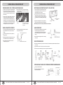
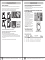
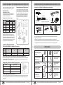
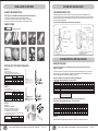
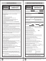
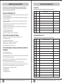
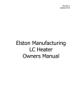
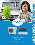
YMGI, A COMFORT MAKER, A JOY COMPANION, A SATISFACTION GUARANTOR...
INSTALLATION & SERVICE MANUAL
Wall Mount Mini Split Systems
M3
Single-Zone
Cooling and Heat Pump W or W/O Heater
(This Installation Instruction is Good for Mini Split Wall Mount Product Line of Different Brands
Made by YMGI Group-YMGI, YMGI Products, and Others Claimed by YMGI Group,
POB 1559, O'Fallon, MO, USA-Check with [email protected] or [email protected])
Literature Part No: Lit-WMMS-0103-20100814
For WMMS Series of Product 09 to 60K Btu/h Single-Zone (Cooling, Heat Pump W or W/O Ele. Heater)
Subject to Continuous Engineering Improvement without Prior Notice.
This product is designed and manufactured free from defects in material and workmanship under the normal use and
maintenance. Installation, operation, maintenance and service shall follow professional practices for regular cooling and
heating equipment, NEC, State, City or Local Codes and related manuals from us. Otherwise, damage to equipment or
property even injury to people may occur.
Installer: Currently licensed HVAC installer only, Read this manual before installation. Sign on the warranty registration card.
User: Keep this manual for future maintenance and service use.
Servicer: Use this manual for service reference.
Literature Part No: LIT-WMMS-II-0103-20100814
VERY IMPORTANT NOTES FOR END USERS (CUSTOMERS) AND INSTALLATION
CONTENTS
VERY IMPORTANT NOTES FOR END USERS (CUSTOMERS) AND INSTALLATION
BEFORE INSTALLATION IDENTIFY COMPONENTS
CONNECTION OF WIRES-SINGLE ZONE
CONNECTION OF WIRES
GET READY FOR INSTALLATION
OPERATING TEMPERATURE RANGES
INDOOR UNIT-MAJOR COMPONENTS
REMOTE CONTROL
ATTENTIONS-MUST READ AND FOLLOW THE FOLLOWING, PRIOR TO CONNECTING REFRIGERANT LINES
BRIEF INTRODUCTION TO MINI SPLIT WALL MOUNT SYSTEM
IMPORTANT NOTES
IMPORTANT NOTES FOR UNIT OPERATION ABMIENT & SIZING
CONTROL SPECIFICATION
INTRODUCTION
INSTALLATION POSITIONS FOR OUTDOOR UNIT
HEIGHT LIMITS OF INDOOR AND OUTDOOR UNITS
DURING INSTALLATION-INDOOR UNIT
INSTALLATION-OUTDOOR UNIT
WIRING OUTDOOR UNIT
CONNECT REFRIGERANT PIPES BETWEEN INDOOR AND OUTDOOR UNITS
PIPING GUIDE
INSTALLATION ACCESSORIES
VACUUM AND LEAKAGE CHECK
SYSTEM INSPECTION AND TRIAL RUNNING
CHECK AFTER INSTALLATION AND TEST OPERATION
DURING INSTALLATION
USER NOTES AND SERVICE LOG
LIMITED PRODUCT WARRANTY REGISTRATION CARD
WARRANTY AND TECH. SUPPORT
USER NOTES AND SERVICE LOG
2
3
4
5
5
7
8
9
10
11
12
15
16
17
19
19
20
23
24
25
26
27
28
28
29
30
31
32
33
34
1. GOOD UNITS CAN MALFUNCTION, MAY NOT WORK CORRECTLY OR PROPERLY, AS DESIGNED AND
MANUFACTURED, IF NOT INSTALLED CORRECTLY OR PROPERLY. MUST DO IT RIGHT ALL THE TIME,
ESPECIALLY FROM THE VERY BEGINNING.
2. CUSTOMER DO-IT-YOURSELF (DIY) INSTALLATION CAUSED AND/OR MAY CAUSE TROUBLE, IN
DIFFERENT FORMATS, TO THE UNIT, YOUR COMFORT EXPECTATION, YOUR HEALTH.
3. HANDY MAN OR SMART PEOPLE OR EVEN SOME PROFESSIONALS MAKE MISTAKE SOMEWHERE OR
SOMETIMES. DON'T TRY TO SAVE MONEY BY DIY, HANDLE THE INSTALLATION TO THE CURRENTLY
LICENSED PROFESSIONALS, SINCE THEY WILL TAKE CARE OF YOUR UNITS AND YOUR COMFORT.
4. DIY INSTALLATION MAY SAVE YOUR SOME MONEY AT THE FRONT, BUT WILL COST YOU MORE AND
BRING HEADACHE, DOWN THE ROAD.
5. YMGI DOESN'T AGREE, DOESN'T ALLOW, DOESN'T WARRANT, DOESN'T ENSURE, DOESN'T
ENCOURAGE, DOESN'T RECOMMEND DIY INSTALLATION, UNLESS YMGI STATES DIY
INSTALLATION IS ALLOWED, IN WRITING.
6. CUSTOMERS WILL LOSE FACTORY WARRANTY ON DIY INSTALLED HVAC PRODUCTS AND TAKE
THEIR RISKS FOR DIY INSTALLATION.
7. DON'T PAY THE CONTRACTOR IN FULL, UNTIL ALL FUNCTIONS OF THE SYSTEM HAVE BEEN
CHECKED AND YOU ARE SATISFIED.
8. IT IS THE INSTALLATION CONTRACTOR'S RESPONSIBILITY TO INSTALL AND SERVICE THE SYSTEM
TO MAKE SURE THE UNIT WORK CORRECTLY AND PROPERLY OVER THE TIME. YMGI DOESN'T
INSTALL NOR SERVICE YOUR UNITS ON BEHALF OF THE INSTALLER. YMGI WILL HELP THE
INSTALLER OR SERVICE PROVIDER ANSWERING QUESTIONS AND PROVIDING TECHNICAL SUPPORT.
9. IT IS THE CUSTOMER'S RESPONSIBILITY TO SELECT THE UNIT CORRECTLY (UNIT SIZE, SEER,
ELECTRIC POWER, CONTROL, REFRIGERANT, DC OR FIXED SPEED, LOOKING AND OTHERS).
10. IT IS THE CUSTOMER'S DECISION WHAT UNIT TO BUY AND TO INSTALL. PUT DOWN ALL
REQUIREMENTS IN WRITING, BEFORE ORDERING.
All Units Shall Be Installed by Experienced or Licensed Contractor Or
Technician. Read Manuals before Installation.
11. WHO CAN INSTALL THE HAVC PRODUCTS HEREOF:
* ONLY LICENSED HVAC CONTRACTOR(S)/TECHNIICIAN(S), WHO KEEPS CURRENTLY VALID LICENSE
FOR HEATING AND COOLING EQUIPMENT, SUCH AS AIR CONDITIONER AND HEAT PUMP.
Following NEC, State and Local Codes and Installation Instructions of All
Units, Otherwise Unit Warranty Will Be Void and Serious Damage To People Or Property May Be
Caused.
* DON'T DO-IT-YOURSELF (DIY) HVAC EQUIPMENT, WHICH IS NOT ALLOWED BY THE LAWS, NOR
WARRANTED BY YMGI.
12. IMPORTANT NOTES FOR INSTALLATION
* SIZE WIRES AND CIRCUIT BREAKERS CORRECTLY, PER NEC CODES.
YMGI Group Shall NOT Take Any Responsibilities for Any Damage or
Loss Due to Do-It-Yourself(DIY) self-installation and other Improper Installation or Operation or
Natural Disaster.
* READ SPECIFICATION SHEETS OR OTHER MANTERIALS FOR LIMITS OF OPERATING TEMPERATURE
RANAGES, PIPING LENGTH, AND PERFORMANCE AT DIFFERENT AMBIENT TEMPERATURES.
Don't Supply Power until All Wiring and Tubing and Checking is
Completed. Ground the Unit Following Instructions and NEC, State and Local Codes.
Connect All Wiring Securely. Loose Wire or Other Bad Contact May Cause
Arc or Overheating and Fire Hazard.
End User Technician Contact of Technical Support-Manufacturer
Toll Free Number: 1-866-833-3138 x 703
Email: [email protected]
THE ROAD.
* VACUUM THE INTERCONNECTING TUBES AND INDOOR UNITS AND CHECK FOR LEAKAGE,
BEFORE RELEASING REFRIGERANT FROM OUTDOOR UNIT TO INDOOR UNIT.
* TRIAL RUNNING SYSTEMS AND CHECK ALL FUNCTIONS, BEFORE PAYING OR LETTING THE
(End user needs to contact installation or service technician to check the unit, before the
technicians contact manufacturer technical support-straight technical communication)
YMGI, A COMFORT MAKER, A JOY COMPANION, A SATISFACTION GUARANTOR...
* READ MANUALS AND CHECK TO MAKE ALL ARE CLEAR BEFORE INSTALLING THE UNITS.
* WATCH INSTALLATION AND MAKE SURE THERE ARE NO BUGS LEFT IN YOUR HAVC SYSTEMS.
* COVER THE ENDS OF THE INTER-CONNECTING COPPER TUBES BEFORE PULLING THROUGH
STRUCTURES TO KEEP FROM DIRTY OR OTHER FOREIGN SUBSTANCES ENTERING THE
REFRIGERATION SYSTEM TO CONTAMINATE THE SYSTEM AND DAMAGE THE SYSTEM, DOWN
P1 OF 34
INSTALLER LEAVE THE JOB SITE.
* JOT DOWN INSTALLER'S CONTACT INFORMATION AND SERVICE INVOICE/RECIEPT FOR FUTURE
QUESTIONS OR CUSTOMER SERVICE.
YMGI, A COMFORT MAKER, A JOY COMPANION, A SATISFACTION GUARANTOR...
P2 OF 34
BEFORE INSTALLATION IDENTIFY COMPONENTS
CONNECTION OF WIRES-SINGLE ZONE
WIRING AT INDOOR UNIT AND OUTDOOR UNITS
INDOOR UNIT
* Open the front cover panel.
* Remove screws from electrical box cover and put screws in secured position.
* Remove screws from fastener and put screws in secured position.
* Prepare wires of right size and grade.
* Recommend to use factory-provided wire/cables.
* Connected to the terminals following wiring diagrams (terminal or color matches).
* Clamp power/control wires to the structure to keep the tension form being transmitted to the wire connection.
* Replace screws or fasteners back to where they were.
Air Inlet
Air Intake Grilles
Temperature Sensor
AC-09/12K Models(110/1/60)
Front (surface)
Panel
Wiring Cover
AC-09/12/18/24K Models (208~230/1/60)
G
L
N
Front (surface)
Panel
2
Wiring Cover
L1 L2
G
2
Emergency Switch
Indicating Lamp &
Signal Receiving
Window
Teminal block
of indoor unit
(To outdoor
unit)
Indoor Unit
Horizontal Louver
Outdoor Unit
Indoor Unit
Outdoor Unit
Terminal match
G
L
N
Teminal block
of indoor unit
(To outdoor
unit)
L
2
Terminal match
G
L1
L2
L
2
Vertical Louver
Air Outlet
Air Filter
OUTDOOR UNIT
HP-09/12K Models (110/1/60)
Remote Controller
Front (surface)
Panel
Wiring Cover
G
L
N
2
Indoor Unit
Outdoor Unit
Terminal match
G
L
N
2
3
Front (surface)
Panel
4
4
Wiring Cover
Teminal block
of indoor unit
(To outdoor
unit)
Indoor Unit
Outdoor Unit
G L1 L2 2
3
4
Defrost Cable
Teminal block
of indoor unit
(To outdoor
unit)
Drainage Hose
3
Defrost Cable
Air Inlet
Connecting Pipe
and Cable
HP-09/12/18/24K Models (208~230/1/60)
Terminal match
G
L1
L2
2
3
4
Air Outlet
Unit Appearance and Specifications Are Subject to Change for Continuous Improvement without Any Prior Notice.
YMGI, A COMFORT MAKER, A JOY COMPANION, A SATISFACTION GUARANTOR...
P3 OF 34
YMGI, A COMFORT MAKER, A JOY COMPANION, A SATISFACTION GUARANTOR...
P4 OF 34
CONNECTION OF WIRES
GET READY FOR INSTALLATION
PIPING AND WIRING SIZES
Model
LIST OF RECOMMENDED TOOL
Power Wire
Min/Max.
Liquid/
Disconnect Switch Box to
Length/
Gas Line
+/-Elevation Outdoor Unit
Power/ Control Wire
Outdoor to Indoor Unit
HVAC Circuit
Breaker/Fuse AMP
(to Outdoor Unit)
09K
1/4” & 3/8”
15/70/25/35
L/N/G, 115/1/60, 14AWG
Power: L/N/G
Control: AC-2 HP-2/3/4
20/10
12K
1/4” & 1/2”
15/70/25/35
L/N/G, 115/1/60, 14AWG
Power: L/N/G
Control: AC-2 HP-2/3/4
25/10
18K
3/8” & 5/8”
15/100/30/50
L1/L2/G, 208-230/1/60, 14AWG
Power: L1/L2/G
Control: AC-2 HP-2/3/4
20
24K
3/8” & 5/8”
15/100/30/50
L1/L2/G, 208-230/1/60, 14AWG
Power: L1/L2/G
Control: AC-2 HP-2/3/4
25
Note:
* The environment conditions must be taken into consideration when the connections of power cable are made
(such as the ambient temperature, direct exposure to heat/dirext exposure to sunlight).
* The specifications for the power cable refer to the minimum values of the metal core wires, taking into
consideration the voltage losses, the core wire of power cable must be one size larger than the specifications.
* The grounding wire must be connected to the indoor units and outdoor units.
* The laying of power cables must be done by qualified electricians and comply with the regulations of the local
power supply authorities and with the standards of the electric appliance.
1
Screw driver-Phillips-bigger
2
Screw driver-Phillips-smaller
3
Copper tube cutter
4
Copper tube flare expander
5
Wire stripper
6
7
Manifold (R410A)
8
Scissor
Vacuum pump
9
Plier
10
11
Wrentch
Multiple-purpose meter
12
Tape measure
Vacuum Copper Pipe Indoor unit before Releasing Refrigerant from Outdoor Unit to Indoor Unit.
GET READY FOR INSTALLATION
MISC. ITEMS COMING WITH INDOOR UNIT
1
Mounting plate
1 Pcs.
2
Manuals (User/ Installation/ Wiring/ Diagram)
1 Set
3
Remote controller
1 Pcs.
4
Battery
2 Pcs.
5
Drain spout for outdoor drain pain
1 Pcs.
6
Warranty registration card
1 Pcs.
7
QC Pass
1 Pcs.
Hexagon Allen wrench
(Front seat to close,
back seat to open)
Service valve
OPTIONAL ACCESSORIES THAT ARE PACKAGED AND MAY BE SOLD SEPARATELY
1
Installation kit (copper line/wire/drain hose & others)
2
Power and control and or intercommunication cable
3
Foot rise or brackets for outdoor unit
4
Line set covers
5
Wind baffie
YMGI, A COMFORT MAKER, A JOY COMPANION, A SATISFACTION GUARANTOR...
P5 OF 34
YMGI, A COMFORT MAKER, A JOY COMPANION, A SATISFACTION GUARANTOR...
P6 OF 34
OPERATING TEMPERATURE RANGES
INDOOR UNIT-MAJOR COMPONENTS
These units are designed for general T-1 weather conditions as outlined in the following table:
Recommended Temperature
Recommended Temperature
Ranges-Indoor Side
Ranges-Outdoor Side
Mode
Dry Bulb
Wet Bulb
Mode
Dry Bulb
Cooling
61 to 1050F (16 to 40.50C)
NA
Cooling
45 to 115oF (7 to 46.1oC)
Heating
0
0
17 to 86 F (-8 to 30 C)
0
0
17-42 F (-8 to 5 C)
Heating
o
Since outdoor units can be installed on the wall or balcony, where is close to indoor unit, at least the following
benefits will be brought to contractors and customers:
Wet Bulb
o
17 to 75 F (-8 to 23.8 C)
NA
o
17-35 F (-8 to 2oC)
IMPORTANT NOTES:
1) Working temperature ranges listed above are guaranteed for units to work properly, though these temperature
ranges are conservative.
2) Units may still work well out of the guaranteed working temperature ranges, as long as they are installed
properly and are still in good conditions within design envelop.
3) Units are designed for mild low temperature AC cooling applications. Units come with low temperature control
to protect agent too low pressure when running for AC cooling in weather colder than 45oF and warmer than
35oF. In this temperature ranges, units may not need to add refrigerant and/or jumper at low pressure switch.
If units are to be used for cooling only below 35oF, then better to check and add refrigerant and jumper at low
pressure switch. Situation varies upon indoor load and indoor unit installation conditions such as TEX type,
elevation vs outdoor unit, copper line set size and length, refrigerant level and leakage level.
4) Units may still work HP heating well way below 17oF, though exact temperatures are not listed. Units will
defrost during HP heating model in cold weather. Suction (bigger) pipe should be hot and the discharge
(smaller) pipe should be warm at outdoor unit during HP heating mode, if everything is right.
* Indoor unit operates much quieter than air diffuser of central air conditioning system.
* Stylish design of indoor unit adds beauty to rooms.
* Connection pipe, refrigerant usage is much saved compared to installing up-flow condensing units on the
ground and long copper/wire lines needed between indoor and outdoor units.
* Contractor work is eased and time is saved.
* Efficiency and lifetime of system is increased.
Mini Split Wall Mount Systems come with three types: cooling only and heat pump and heat pump with electric
heater. These units can be easily wired. Either indoor unit or outdoor unit can be used with any matched
comparable outdoor unit or indoor unit as long as they have matched size and control. Must refer to electrician
before doing so.
Each system is fully tested per rigorous standards at factory. Acoustically and thermally balanced design and
systematically optimized system give each unit a healthy birth off the assembly line with proved quality and
reliability.
Find the cooling/heating load capacity of the space where the unit will be in service. Select matched WMMS
units for the space. Under sizing or over sizing equipment is NOT recommended.
INDOOR UNIT-MAJOR COMPONENTS
Air Filter
Front Panel or Faceplate
Air Inlets
5) Optional component Wind Baffle installed at fan discharge side on the cabinet is designed to keep from cold
air blowing into propeller fan blade against airflow, and so help unit work better in both AC cooling and HP
heating mode in colder weather ranges.
Since outdoor units can be installed on the wall or balcony, where is close to indoor unit, at least the following
benefits will be brought to contractors and customers:
* Indoor unit operates much quieter than air diffuser of central air conditioning system.
* Stylish design of indoor unit adds beauty to rooms.
* Connection pipe, refrigerant usage is much saved compared to installing up-flow condensing units on the
ground and long copper/wire lines needed between indoor and outdoor units.
* Contractor work is eased and time is saved.
* Efficiency and lifetime of system is increased.
Mini Split Wall Mount Systems come with three types: cooling only and heat pump and heat pump with electric
heater. These units can be easily wired. Either indoor unit or outdoor unit can be used with any matched
comparable outdoor unit or indoor unit as long as they have matched size and control. Must refer to electrician
before doing so.
Each system is fully tested per rigorous standards at factory. Acoustically and thermally balanced design and
systematically optimized system give each unit a healthy birth off the assembly line with proved quality and
reliability.
Find the cooling/heating load capacity of the space where the unit will be in service. Select matched WMMS
units for the space. Under sizing or over sizing equipment is NOT recommended.
Too Cold
Not Cold
Too Hot
Display
Manual Louvers
(Side to Side)
Auto-Directional Louvers
(Up and Down)
Not Hot
Test/Reset Switch
Remote Control (or Optional Wall Thermostat)
YMGI, A COMFORT MAKER, A JOY COMPANION, A SATISFACTION GUARANTOR...
P7 OF 34
YMGI, A COMFORT MAKER, A JOY COMPANION, A SATISFACTION GUARANTOR...
P8 OF 34
ATTENTIONS-MUST READ AND FOLLOW THE FOLLOWING, PRIOR TO CONNECTING REFRIGERANT LINES
REMOTE CONTROL
1. Metering device is installed in this outdoor condensing unit, no other metering device needs to be field-installed
anywhere else.
2. One refrigerant filter/strainer is installed in the outdoor unit, no other filter/strainer needs to be field-installed
anywhere else, otherwise it may cause extra pressure drop and even system under-performance or other
problems.
3. If a refrigerant drier is to be field-installed, must be of enough size and correct flow-direction, following drier
manufacturer's instruction. Fail to do so may cause unit problems.
4. Must check the indoor unit for leakage by checking if the indoor unit still holds the pressurized charge, by
breaking the seal left at indoor refrigerant copper line connection, before connecting it to the inter-connecting
refrigerant copper lines. If for some reason the break is made before you check it, must pressurize it and
SWING BUTTON
check for leakage.
5. Professionally conduct general refrigeration practice to connect copper lines and seal-tight correctly and
properly. Must insulate and secure both discharge and suction copper lines.
LED DISPLAY
6. Must keep the two valves at outdoor condensing unit front-seated (closed), and pressurize the refrigerant flow
cavities between the inter-connecting copper lines and indoor unit to check leakage, before move on to
conduct vacuum leakage test (20-30 minutes under 500 microns recommended).
MODE BUTTON
7. Then back-seat (open) the two valves to release refrigerant factory-precharged in the outdoor condensing unit,
into the inter-connecting refrigerant copper lines and indoor unit, ONLY if the system leakage is checked and
passed (pressurization and vacuum check).
8. Must check all thermal functions at the final stage of installation. Both liquid and gas lines at outdoor
condensing unit valves, should be cold at cooling mode, and hot at heat pump mode. If not cold or hot (E4 or
E5 error code may show up at indoor unit to shut off the system and warn for system checking, must contact
installer or service provider to check refrigerant charge and/or other items, accordingly. How cold or how hot it
needs to be, varies upon ambient temperature, refrigerant charge/pipe length, indoor unit conditions and so on.
SLEEP BUTTON
LED BUTTON
SET BUTTON
9. Adjust/check the refrigerant charge per pressure/temperature (super-heat or sub-cooling) at the service valves,
or length of copper pipes, following the pressure-ambient temperature chart or 25' breaking point rule as
factory-recommended in the installation manual.
TIMER BUTTON
ADJUSTMENT BUTTON
FAN SPEED BUTTON
LIGHT WAVE BUTTON
ELECTRIC HEATING BUTTON
IONIZER BUTTON
RUN/STOP BUTTON
AUTO CLEAR BUTTON
FRESH AIR BUTTON
YMGI, A COMFORT MAKER, A JOY COMPANION, A SATISFACTION GUARANTOR...
P9 OF 34
YMGI, A COMFORT MAKER, A JOY COMPANION, A SATISFACTION GUARANTOR...
P10 OF 34
BRIEF INTRODUCTION TO MINI SPLIT WALL MOUNT SYSTEM
Mini Split Wall Mount Systems are designed for high performance, easy installation and service. Each system
consists of one or several indoor units and one outdoor unit, which are connected by one set or several multiple
sets of interconnection refrigerant pipes and electric wires.
As shown in the following sample picture of outdoor unit, air is drawn through the coil from the rear side and then
discharged from the front side. In cooling mode, air passing through coil is heated; in heating mode, air passing
through coil is cooled.
Air In
IMPORTANT NOTES
SAFETY WARNINGS
READ THESE SAFETY WARNINGS COMPLETELY PRIOR TO ANY USE.
Ground connection
Forbidden
Disconnect the plug
Imperative
These precautions are essential and must be strictly observed.
DO NOT draw on the power cord or refrigeration
lines. Install them in secured positions. Plastic
cover of line set is recommended.
DO NOT blow the cold air directly towards people
for prolonged period. Otherwise, people may get
cold.
DO NOT use smaller than enough wires. Do not
put several circuits to one breaker. Don't use
smaller than enough circuit breakers. Otherwise
power failure or fire may be caused.
DO NOT wire or open unit while unit is running.
Sparks or fire may occur. It may cause a shock to
people.
DO NOT pull on the power cord or refrigeration lines.
Install them in a secured position. A line set plastic
cover is recommended.
DO NOT install the indoor unit close to cooking
surfaces or ventilation systems. Poor placement
could inhibit peak performance.
DO NOT install the unit in places where there is
exposure to flammable materials or gas leakage.
DO NOT blow cold air directly towards people for
extended periods. It may get you a bad cold.
DO NOT use wire or circuit breakers that do not meet
electrical safety standards. Several circuits cannot
be connected to one breaker.
DO NOT use chemical solvents, flammable
insecticides, or abrasive materials. Clean the unit
only with a soft dry cloth or rag.
DO NOT wire or open the unit while it is running.
Make sure to shut off all circuits prior to inspecting or
servicing the unit.
DO NOT continue to operate the unit if there is any
abnormal odor, burning, scorching, or smoke. Stop
and disconnect the unit immediately.
DO NOT install unit in a damp laundry room or near
flammable gas. All units must be protected by
certified electrical circuit breakers and in accordance
with all safety codes.
DO NOT use the system for anything other than what
it was designed for or any non-HVAC purposes. Do
not store near food, paint, or other chemicals.
Air Out
Sample Wall Mount Mini Split System (For Continuous Engineering Improvement and Various Marketing
Needs and Actual Part Availability Reason, Unit Appearance Subject to Change or Update Continuously
without Prior Notice)
Outdoor unit(s) provides the electrical and thermal power for the whole system. Electrical and thermal
components such as compressors and motors and heat exchange coils and others, are incorporated into the
cabinet in an optimized order. They can be either hung on the wall or installed on the ground. Once stacking or
bracket kit is used, some outdoor units can be stacked 2 or 3 units high, upon unit size and applications. Air is
discharged horizontally, quietly and smoothly. These units are perfect fit in locations where installation and
applications of general up-flow condensing units are limited, such as apartments, condos, lofts, multi-families and
high-rise buildings and others named or unnamed.
Indoor unit(s) delivers the thermal and acoustical comfort to the rooms. Air is drawn through the coil from the
front or topside and then discharged from the bottom. In cooling mode, air passing through coil is cooled; in
heating mode, air passing through coil is heated. Air is filtered or treated by the built in mechanism (washable or
enzyme equipped or electrostatic powered filter, varies from model to model), before being delivered into the
room, with more than enough comfort and care, at a wide angle (swing or not, varies from model to model).
Apartments
Office Buildings
Homes
Application Samples of Wall Mount Mini Split Systems
NOTES: Since ductless system is not designed to incorporate or use with ducted return or discharge tunnels, one
single-zone unit SHALL NOT be used to take care of the cooling or heating load of more than one-story room.
Several single-zone ductless systems or multiple-zone ductless systems shall be proper in this regard.
These units are designed for applications at:
* Residential
* Light commercial
* Institutional
* Industrial
* Commercial
* Hospital
YMGI, A COMFORT MAKER, A JOY COMPANION, A SATISFACTION GUARANTOR...
DO NOT use the unit in cool or dry mode for
prolonged periods where humidity is higher than 80%.
P11 OF 34
DO NOT operate the unit for prolonged periods
without refreshing ambient air. Opening a door or
window periodically will suffice.
YMGI, A COMFORT MAKER, A JOY COMPANION, A SATISFACTION GUARANTOR...
P12 OF 34
IMPORTANT NOTES
IMPORTANT NOTES
* Good unit may not work properly or correctly. as designed or manufactured, if not installed properly or correctly.
* Customer do-it-yourself (DIY) installation caused and/or will cause trouble to the unit and your property and
yourself.
* YMGI doesn’t allow nor recommend nor honor warranty for DIY installation. Customers take full responsibility
for DIY installation.
* DIY installation may save money at the front, but cost you more down the road, money and other headache.
YMGI is NOT and shall NOT be responsible for any problems due to customer do it yourself(DIY) installation,
non-licensed installation, and other unprofessional, incorrect, incomplete installation, abuse to the unit, or
abnormal usage which would be considered outside normal constraints, or recommended ranges, and natural
disasters such as fire, flood, earthquake, lighting, or others similar.
SAFETY CAUTIONS AND ALERTS
YMGI IS NOT AND SHALL NOT BE RESPONSIBLE FOR:
Installation, Operation, Maintenance, and Service shall follow professional standards and practices for
conventional cooling and heating equipment, under International, National, State, City or Local Codes, and follow
guidelines listed in all related manuals and associated product information provided directly, from YMGI. Failure
to adhere to proper Installation, Operation, Maintenance, and Service could result in unit malfunction damage to
equipment, personal property, or physical injury, or even death, which YMGI is not responsible for.
Damage to the units or property or person due to
careless, or incautious, or rough handing at job site,
such as pulling wires or pipes or plastic parts too hard,
dropping units, robbing unit surfaces, and etc.
Installation must be performed following the
YMGI Installation/Maintenance Manuals.
Installation must be performed by a certified
technical installer only. DO NOT attempt to install
the unit by yourself trying to save money. Do-ItYourself (DIY) installation will void YMGI provided
warranty and could result in injury or death, or
property damage due to fire, electrical shock, leaking,
collapsing, which YMGI is not responsible for.
Install the unit onto a strong load bearing
structure. The location must be capable of handling
the weight load of the unit to prevent the unit from
falling or causing injury. Attach both the indoor and
outdoor units to the brackets that are fixed to the
right position securely.
Only use manufacturer specified and codes
allowed wires and conduits to connect to the
units so the stress is not applied to the sections.
Incomplete connecting and insecure fixing could
cause fire or damage.
Wiring must conform to national regulations.
Failure to adhere to these standards could result in
personal injury or death or property damage due to
fire, electrical shock, falling units, or leaking.
Connect the power cord directly to a designated
and exclusive AC Power Circuit Breaker and or
Disconnect Switch. The circuit must exceed
permissible currents and is free of insulation and
contact defects. Shall refrain from intermediate or
multiple connections to avoid fire or electric shock.
DO NOT supply power until all wiring and tubing
is checked completely.
Double check for gas leaks during or after
installation. The refrigerant gas may cause harmful
substances when subjected to heat or fire.
Refrigerant leakage will cause unit not to generate
enough cooling or heating and even damage
compressors and other parts.
Shut off the main power prior to and during
installation to avoid electrical shock. Make sure
that the electrical power is disconnected from the
unit by making a notice or put a sign at the power
switch panel, to keep other people from setting the
power back during installation.
Connect all wiring securely. Any loose wire or other
bad contact may cause an electrical arc, overheating,
or fire hazard. Make sure that the unit is grounded
following YMGI Instructions and NEC, International,
State, City, and Local Codes. Electrical cover shall be
securely attached to the indoor and outdoor unit
service panels, otherwise, could result in fire or
electric shock due to accumulation of dust, sediments,
water, moisture, etc.
Only use authorized YMGI parts in the
installation, maintenance, service, and repair of
YMGI units. The use of non-authorized or
defective parts will void the warranty and could
cause injury or death or property damage due to
water leakage, falling units, fire, electric shock, etc.
Pay extreme caution to interconnecting
refrigerant copper tubing, when installing or
relocating the unit. Make sure that no other
substance than the specified refrigerant enters the
refrigeration circuit. Any presence of foreign
substances such as air or water or moisture can
cause an abnormal pressure rise or overheat, which
will result in an inefficient unit performance or unit
malfunctions, and will shorten unit lifetime.
Pay extreme caution to interconnecting
refrigerant copper tubing when installing or
relocating split system, as applicable.
1) Make sure that no substance other than the
specified refrigerant enters the refrigeration circuit.
Any presence of foreign substances such as air or
water or moisture can cause an abnormal
pressure or overheat which will result in an
inefficient unit performance or unit malfunction and
will shorten the longevity of the unit.
2) Tape two ends of the copper tubing, tape the
wires for the corresponding indoor
unit to the copper tubing, and mark well with either
A, B, C or D to identify each copper tubing/wiring
bundle. Do not cross wire or mismatch tubing
among indoor units of the multiple zone systems.
Connect the electrical wiring and copper tubing
from each zone of indoor unit to the corresponding
wiring and copper tubing connections of the
corresponding outdoor section (at outdoor
condensing unit). Failure to do so will cause unit
malfunctions, or damages to the compressors and
other parts in the unit and even property or
personal injuries.
YMGI, A COMFORT MAKER, A JOY COMPANION, A SATISFACTION GUARANTOR...
P13 OF 34
YMGI LIABILITY DISCLAIMER
Damage to the units or property or person due to
unprofessional or incorrect or incomplete mechanical
installation of units. Examples, not limited to, are:
sharp bending, not finding kinks, cracking or
deterioration of connecting pipes, unevenly sitting
units, not securing the units, not cleaning or leaving
dirty inside of or not tightening interconnecting pipes,
not finding refrigerant or water leakage, not
vacuuming, not opening
refrigerant stopping valves at condensing units, not
checking pressures, not covering bared refrigerant
pipes and connections, not taping wire connections,
not sealing drain pipe connections, incorrect piping
such as crossing piping among multiple zones, and etc.
Accumulated costs, services, or disasters due to
unprofessional or incorrect or incomplete installation,
or abnormal usage of the units.
Under performance or damage to the unit, property
or person, at low vacuum level due to unprofessional
or incautious or bad installation, or damage to the
unit or interconnecting pipes after installation and
during usage.
Under performance or damage due to exceeding
the recommended distances or elevation levels
between indoor and outdoor units.
Under performance or damage due to the presence
of any foreign substances left inside refrigeration pipes.
Under performance or damage due to the materials
left in the air-conditioner during installation.
Under performance due to poor installation or
abnormal usage in other formats.
Water leakage problems due to incorrect or poor
installation or unsealed drain hoses.
Damage due to refrigerant or oil leakage as a result
of unsuccessful pipe installation or damage to the
unit and or pipes during or after installation.
Damage due to supplying power before all wiring
and tubing is completely finished and checked.
Damage due to not keeping units in the right
positions during handling, installation or operation.
Damage to the units or property or person due to
customer do it yourself(DIY) installation, non-licensed
installation, and other unprofessional or incorrect or
incomplete mechanical or electrical installation not
mentioned above.
Damage to the units or property or person due to any
other Improper Usage not conforming to YMGI
user regulations, user operation manuals and factory
recommendations.
Under performance or damage due to operating the
air conditioning system under poor physical
conditions such as anywhere there is airflow
blockage, too much sunshine, too much corrosive
gas or the sort.
Under performance or damage due to the Usage
outside the YMGI recommended operation
ambient conditions including proper temperature and
humidity ranges.
Under performance or damage due to the undersized
or oversized unit selection, improper design, incorrect
unit anticipation, and the sort.
Damage due to not grounding or poorly grounding
unit, incorrectly wiring units, loose or unsecured
wiring, or other bad contact which may cause an
electrical arc, overheating, or fire hazard.
Damage or repairs required as a consequence of
faulty installation or application.
Damage due to failure to start as a consequence of
exceeding recommended voltage ranges (too low or
too high), blown fuses, open circuit breakers.
Damage due to the inadequacy or interruption of
electrical service.
Damage or repairs needed as a consequence of
any misapplication, abuse, improper servicing,
unauthorized alteration, or improper operation.
Damage due to the usage of parts not supplied or
designated by YMGI Group.
Damage to the unit, property, and/or person of
whatever kind, direct or indirect, special or
consequential, resulting from the improper
installation or usage of such products.
Damage from the units installed and operated
outside USA or Canada.
Damage as a result of floods, winds, fires, lightening,
accidents, corrosive atmosphere, or other conditions
beyond the control of YMGI Group.
YMGI, A COMFORT MAKER, A JOY COMPANION, A SATISFACTION GUARANTOR...
P14 OF 34
IMPORTANT NOTES FOR UNIT OPERATION ABMIENT & SIZING
DRY MODE
OPTIONS AT MANUFACTURE OR AFTER SALES:
* Advanced Health Kits (HEPA/Enzyme/
Cold Catalyst Filter, Light Wave, Or,
Anion Generator)
* Treated Coil
* Plug & Connect Copper Line Set
* Rust-free Cabinet
* Plug & Connect Valves
* Low Ambient Control
* Wall Mount Line Control
* Cabled Defrost Control
System Model
COOLING ONLY
WMMS-18K-31B
WMMS-12E-31A
WMMS-18E-31B
WMMS-24E-31B
Outdoor Unit
WMMS-09C-31A
WMMS-12C-31A
WMMS-18C-31B
WMMS-24C-31B
WMMS-09K-32A
WMMS-12K-32A
WMMS-18K-32B
WMMS-24K-32B
Indoor Unit
WMMS-09E-32A
WMMS-12E-32A
WMMS-18E-32B
WMMS-24E-32B
Outdoor Unit
WMMS-09C-32A
WMMS-12C-32A
WMMS-18C-32B
WMMS-24C-32B
WMMS-09K-34B
WMMS-12K-34B
WMMS-18K-34B
WMMS-24K-34B
Indoor Unit
WMMS-09E-34B
WMMS-12E-34B
WMMS-18E-34B
WMMS-24E-34B
Outdoor Unit
WMMS-09C-32B
WMMS-12C-32B
WMMS-18C-32B
WMMS-24C-32B
INST-1438-xx
INST-1412-xx
INST-3858-xx
INST-3858-xx
9000
12000
18000
24000
12800 (7780)
19000 (11350)
System Model
REF. TUBE/WIRE INS. KIT
MODELS
Copper Sets, Wiring, Putty, Wall Sleeve, Wrap, Drain Hose
COOLING CAPACITY
Rated ID 80/67F OD 95F
HEATING CAPACITY
Rated ID 70/60F OD 47F (17F)
WMMS-24K-31B
WMMS-12K-31A
WMMS-09E-31A
MODELS
HEAT PUMP+ELE. HEATER
* Control during dry mode:
WMMS-09K-31A
System Model
HEAT PUMP
* In this mode, the air conditioner automatically sets the room temperature and this temperature is incontrollable
by remote controller. The initial ST=RT-2 .
Indoor Unit
MODELS
BTU/H
1), 2)
BTU/H
1), 2)
9500 (6120)
RECOMMENDED WORKING TEMPERATURE RANGES
COOLING ID/OD (F)
3)
Indoor Side 61 to 105 / Outdoor Side 45 to 115
RECOMMENDED WORKING TEMPERATURE RANGES
HEATING ID/OD (F)
3)
Indoor Side 17 to 86 / Outdoor Side 17 to 75
5)
HEATING BOOSTER(-34B MODELS ONLY)
W(MAX)
800
1000
1200
1200
DEHUMIDIFICATION
RATED
PTS./H
3.4
4.6
6.9
7.6
SEER
RATED
BTU/H.W
13
HSPF
RATED
BTU/H.W
9.2
SOUND LEVEL (Actual)
INDOOR / OUTDOOR
dB(a)
32-41 / 46-53
38-45 / 48-54
REFRIGERANT
PRE-CHARGED FOR 25' TUBING
POWER SOURCE
FROM CIRCUIT BREAKER TO OUTDOOR TO INDOOR UNIT
MCA
HVAC CIRCUIT
BREAKER SIZE
26-34 / 42-51
28-38 / 43-51
R410A
A: 115/1/60
AMP
6.9
8.1
WITH HEATER (34 Models)
AMP
10.4
12.4
6.4
11.6
8.6
13.8
W/O HEATER (31,32 Models)
AMP
8.9
9.5
8.8
10.9
WITH HEATER (34 Models)
AMP
13.0
15.0
14.5
16.8
W/O HEATER (31,32 Models)
AMP
15.0
20.0
20.0
25.0
WITH HEATER (34 Models)
AMP
20.0
25.0
25.0
30.0
TYPE
INDOOR FAN MOTOR
MOTOR (PSC)
CROSS FLOW
OUTDOOR FAN MOTOR
MOTOR (PSC)
HERMETIC
DRAIN
CONNECTION TUBE
ALLOWED MAXIMUM
REF. TUBE
WEIGHT
DIMENSION W
H
D
LOADING CAPACITY
REFRIGERANT
If RT<ST, the compressor runs intermittently as this: Stop for 4 minutes
Run for 1 minute
c) When RT<23 , if RT ST, the compressor runs intermittently as this: Run for 2 minutes
If RT<ST, the compressor runs intermittently as this: Stop for 4 minutes
Stop for 3 minutes
Run for 1 minute
d) In this mode, the indoor fan keeps running at low speed with the same pace as the compressor, and this
speed can not be controlled by remote controller.
AUTO MODE
* In this mode, the air conditioner can automatically adjust the room temperature to decide the most suitable
temperature. At the start of operation, the unit will automatically select the operation mode according to the
room temperature. The following table shows the conditions which are set at start up.
Room
Temperature (RT)
RT
79 F>RT
CFM H/M/L
235/200/185
330/310/235
645/575/515
700/615/560
RATED AMP
0.20
0.40
0.39
0.56
1765
2350
0.60
0.90
77 F>RT
Cool only type
Mode
o
Heat pump type
Initial Setting Temperature
Mode
o
79 F
o
o
o
77 F
Cool
o
73 F
RT<73oF
Dry
75 F
RT-2
RT-2
70oF
Cool
Dry
Initial Setting Temperature
75oF
RT-2
RT-2
79oF
3
SPEED
TYPE
FAN
COMPRESSOR
B: 208-230/1/60
W/O HEATER (31,32 Models)
FAN
a) When RT<15 , dry mode is not available; when RT 15 , the compressor intermittently runs under the
influence of TS and RT.
b) When RT 23 , if RT ST, the compressor runs intermittently as this: Run for 8 minutes Stop for 3 minutes
25000 (15360)
4)
ELECTRIC HEATER (SUP.)
TOTAL CURRENT
CONTROL SPECIFICATION
PROPELLER
CFM
1175
1175
RATED AMP
0.20
0.50
SPEED
1
TYPE
ROTARY
BRAND
Hitachi, Sanyo, Panasonic
* If restart within 2 hours, the unit will resume the same operation mode as before.
If restart after 2 hours, the unit will select the operation mode according to the initial room temperature.
Flexible
DRAIN PIPE
DISCHARGE
1/4"
1/4"
3/8"
3/8"
SUCTION
3/8"
1/2"
5/8"
5/8"
LIFT
FT
25
25
25
25
DROP
FT
25
25
25
25
TOTAL LENGTH
FT
50
50
65
75
INDOOR-NET
LBs
20
24
33
37
INDOOR-GROSS
LBs
25
28
44
46
150
OUTDOOR-NET
LBs
57
81
110
OUTDOOR-GROSS
LBs
65
89
121
172
INDOOR-NET
INCH
31.5x11.5x7.8
33.9x11.5x8.0
42.5x13.0x8.7
49.5x12.8x9.1
INDOOR-BOX
INCH
34.3x14.4x11.0
36.6x14.4x11.0
46.5x16.7x11.9
52.0x16.3x12.8
OUTDOOR-NET
INCH
27.6x21.3x10.0
31.1x21.3x9.7
33.3x26.8x12.2
34.6x31.1x14.2
OUTDOOR-BOX
INCH
31.5x24.4x14.8
35.2x24.4x14.0
39.8x30.1x16.9
40.6x35.5x18.9
20'/40'/40'HQ
SETS
108/228/258
102/220/242
66/138/148
48/98/116
1) Performance rated for matched system at standard conditions-cooling ID 80/67F, OD 95F, heating ID 70/60F, OD 47/43F. Unit performance
varies when weather changes from the standard one.
2) Select equipment capacity/sizes per space load calculation schedule at local design temperatures and cooling & heating hours. Not to
over size or under size equipment.
3) Watch unit operation during extreme weather conditions in summer and winter. After the unit is used for quite a while in these weather, unit
may step into protection mode and stay idle.
4) May work in lower temp if installed with optional low ambient controller. Ref. ICM 326HN.
5) Capacities and efficiency decrease, as outdoor temperature drops.
YMGI, A COMFORT MAKER, A JOY COMPANION, A SATISFACTION GUARANTOR...
* Auto mode entering
a) Once some operation mode is determined, it can not be changed even if the RT has altered.
b) You can change the operation mode by remote controller.
P15 OF 34
* At auto mode the ST can only be set + or - 2 of the RT.
FAN MODE
* Indoor fan runs at the set speed while compressor and outdoor fan are turned off.
* Indoor fan speed can be adjusted for low, medium and high.
SLEEP MODE
Sleep mode in cooling and drying running
A) The indoor fan runs at low speed.
B) After one hour of operation the set temperature will increase by 34oC. One hour later, the set temperature will
increase by 1oC once more. The unit will then continue operating at 36oC above the set temperature.
Sleep mode in heating running
A) The indoor fan runs at low speed.
B) After one hour of operation the set temperature will decrease by 36oC . One hour later, the set temperature will
decrease by 2oC once more. The unit will then continue operating at 39oC below the set temperature.
YMGI, A COMFORT MAKER, A JOY COMPANION, A SATISFACTION GUARANTOR...
P16 OF 34
INTRODUCTION
INTRODUCTION
INSTALLATION LOCATIONS
CLEARANCE REQUIRED AROUND UNITS-SINGLE ZONE
The location and structure shall also be convenient for both installation and service.
The location shall NOT be where discharge air and noise could bother your neighbor.
The location shall NOT be somewhere drain may cause any damage to property or bother the neighbor.
The location shall NOT be somewhere soldering or torching work may cause fire or smoke to the
materials around.
The location shall NOT be somewhere near flammable gases.
The location shall NOT be in or close to corrosive gases.
The location shall NOT be somewhere children can access.
Inspan the unit for damage and missed parts or accessories. If damage is found or parts are found
missing, call the distributor right away.
Spin fan wheels or blades to check if and make sure they can rotate freely. If fan wheel scratches with
housing, call the distributor right away and do not to proceed with the installation before it is fixed.
Check the unit to make sure no foreign materials has been left in the unit.
Check all the parts and accessories that are needed other than those provided with the unit.
It is strongly recommended to only use YMGI supplied or recommended parts and accessories.
Be sure a properly sized circuit breaker is for the electric power to the units.
Pre-build the support platform on the ground or bracket for the wall before or during construction and
before installation. Refer to the table below for footprint dimensions.
Read installation instructions of all units thoroughly.
Ask rep./distributor/us anything you are not sure about.
Get your tools and parts ready for installation.
All Units Shall Be Installed by Licensed Contractor or Technician.
Read Manuals before Installation.
YMGI, A COMFORT MAKER, A JOY COMPANION, A SATISFACTION GUARANTOR...
P17 OF 34
YMGI, A COMFORT MAKER, A JOY COMPANION, A SATISFACTION GUARANTOR...
P18 OF 34
INSTALLATION POSITIONS FOR OUTDOOR UNIT
DURING INSTALLATION-INDOOR UNIT
* To be installed at the position where the air delivered from the unit can reach every comer of the room.
* To avoid being affected by the outdoor air.
* To avoid blockage to the air inlet or outlet of the unit.
* To avoid too much oil smoke or steam.
* To avoid possible generation, inflow, lingering or leakage of flammable gases.
* To avoid high-frequency facilities (such as high frequency arc welders, etc.).
* To avoid the places where acid solutions are frequently used.
* To avoid the places where some special sprayers (sulfides) are frequently used.
* Not to install on top of the musical instruments, TV, computer etc. valuable appliance.
* Not to install a fire alarming device near the air outlet of the unit (during operation, the fire alarm device might
be erroneously triggered by the warm air from the unit).
HEIGHT LIMITS OF INDOOR AND OUTDOOR UNITS
* Either the indoor unit or the outdoor unit can be higher, but the height difference must comply the stated r
equirements.
* Try to reduce the bending of the piping line as much as possible so as to avoid possible negative impacts upon
the performances of the units.
Indoor unit
Outdoor unit
Drop
P-Trap
* Check to make sure the installation location is firm enough to hold the weight of the whole unit and is
convenient to installation, maintenance, service and close to the indoor unit but not causing noise or airflow
issues to neighbour.
* Install Indoor unit. Enough anchor bolts/nuts shall be used to secure mounting plates for indoor units.
Brackets should be at level position.
Install Mounting Plate and Drill Hole for Combination of Copper Line/Wire Cable/Drain Hose
NOTES:
Anchors must be put into the holes, where the solid
arrows are pointing, as shown above, to secure the
mounting plate firmly and to hold the weight of indoor
unit. If more screws/anchors are to be used, make
sure to keep the two holes close to each other, at
least 2 inches apart.
Mounting plate should be attached to the structural
part of the wall. Minimum clearance, as shown below,
is required in order to ensure proper airflow and
enough service room.
Locate the central hole at the stud (firn structure)
At least 12
inches
18" or
more from
sidewall
18" or more
from sidewall
Respect the slope
Anchors of selftappping screw
a
Mounting Plate
c
Plumb
Drill mounting holes
b
to make sure at least
either one of three
dimensions a, b and
c is 16" center to
center.
Mark drill positions. At least 4 anchor holes, one at each perimeter corner of the plate are needed to secure the
plate, where the bold arrows are pointing, as shown in the picture above. Refer to the specification sheet for
unit weight so that enough anchors are installed at proper positions.
Pre-drill guiding holes where are marked for anchors or screws on the wall
Confirm the position of the holes and finish drill to the depth needed for anchors (NOT for screws)
Align mounting plate holes with those holes drilled on the wall and put anchors or screws into the holes to
secure mounting plate.
18 Ft.
Outdoor unit
* Check unit to make sure the unit is good shape and ready to install.
STEPS TO MOUNT PLATE:
* Make P-trap if elevation drop difference is more than 25", as illustrated below.
Lift
INSTALL WALL MOUNT PLATE
Indoor unit
DRILL 3IN HOLE FOR PIPING/WIRING/DRAIN
Locate the centre where the hole will need to
drilled.
Refrigerant Pipe Min/Max. Length, Rise and Drop Height
1,000 Btu/h
Min. Length (Ft.)
Max. Length (Ft.)
Max. Rise Height (Ft.)
Max. Drop Height (Ft.)
09-12
15
50
20
28
18-24
15
75
25
35
30-36
15
100
35
50
Drill the holes of 2.5-3Inch diameter. A down pitch
about 1/4" per foot, as illustrated below, is needed
for the hole, in order to drain the condensate
properly.
Insert ruler
Hole Diameter: 2.5~3 In
Align ruler with straight line
PREPARE INDOOR UNIT- COPPER LINE SET/DRAIN HOSE
If pipes need to come out of the right side (facing
the front of indoor unit) of the indoor unit, snap off
portion 1 on plastic casing.
If pipes need to come out of the bottom side
(facing the front of indoor unit) of the indoor unit,
snap off portion 2 on plastic casing.
If pipes need to come out of the left side (facing
the front of indoor unit) of the indoor unit, snap off
portion 3 on plastic casing.
YMGI, A COMFORT MAKER, A JOY COMPANION, A SATISFACTION GUARANTOR...
P19 OF 34
1
3
2
YMGI, A COMFORT MAKER, A JOY COMPANION, A SATISFACTION GUARANTOR...
P20 OF 34
DURING INSTALLATION-INDOOR UNIT
DURING INSTALLATION-INDOOR UNIT
REFIT DRAIN HOSE FROM THE RIGHT TO THE LEFT SIDE
PREPARE INDOOR UNIT- COPPER LINE SET/DRAIN HOSE
If pipes need to be rerouted to a different direction
from the one preset at factory (towards left side, if
facing the front cover of indoor unit), lay down the
indoor unit on soft cushion or foam. Don't rub the
plastic casing.
In order to keep from pipe damage, need to bend
the copper tubing set gently and slowly (finish
bending no less than 10 seconds/90 degree), by
holding at the root of the original 90 degree bend
nicely and firmly. Don't rub two copper lines during
bending. Better to cut off the insulation and bend
the two pipes one by one, not two together.
If pipes need to come out of the rear side (facing
the front of indoor unit) of the indoor unit, no need
to snap off anything.
Refitting method: remove the drain hose from
original position, without breaking hose. Unplug
the plug at the left side. Apply water-resistant glue
to fit the drain hose and the fitting before securing
it.
Slice the insulation before
bending.
Hold the 90 degree bend root,
bend one tube one time, slowly,
no quicker than 10 seconds/90
degree bend.
Insulation pad (underlay) should be used where
the pipe contacts the wall.
Drain hose coming with indoor unit
Do not pull the drain hose too hard, otherwise it
may get broken.
Drain hose
NOTES: May use some sort of clamp to double secure connections.
Run copper set/wire cables/drain hose through the
wall hole and hang the indoor unit onto the
mounting plate (place the hook on the mounting
plate into the hanging rib at rear side of plastic
casing).
Snap the plastic casing bottom into the mounting
plate, gently .
Before passing drain hose through the hold, wrap
with insulation to keep from possible damage.
The copper pipe and the drain hose must be
wrapped by piping wrap.
Apply water-resistant glue onto the plug and fit it
back into the condensate connection at right side.
Condensate connection
at left side
HANG INDOOR UNIT
INSTALL DRAIN PIPE AT INDOOR
The drain hose must be placed beneath the copper
pipes and MUST NOT be hunched or bended
sharply.
If drain hose needs to be refitted from the original
position (right side) to left side of the indoor unit,
careful handing is very necessary.
SHAPE THE DRAIN HOSE
Drain hose extending to drain line
To drain the condensate easily, the drain hose should be inclined downward (pitched towards drain direction
1/4" per foot).
Figures below from the 2nd to 5th show some incorrect practices.
Drain hose may be extended using the hose coming with the installation list.
2 in or less
from floor
STUFF AND SEAL THE HOLE FOR COPPER LINE SET/WIRE CABLE/DRAIN HOSE
Use putty to seal the wall hole.
Use clamp (pipe fastener) to secure the
pipe at specified position.
YMGI, A COMFORT MAKER, A JOY COMPANION, A SATISFACTION GUARANTOR...
P21 OF 34
Trim the extra portion.
Sealed with putty
Secure the piping/
wiring set with clamp
YMGI, A COMFORT MAKER, A JOY COMPANION, A SATISFACTION GUARANTOR...
P22 OF 34
INSTALLATION-OUTDOOR UNIT
WIRING OUTDOOR UNIT
INSTALL OUTDOOR UNIT
CONNECT WIRING BETWEEN OUTDOOR UNIT AND INDOOR UNIT
Strongly suggest to install the outdoor unit above the ground either on platform or brackets as shown below.
Heat pump unit must be lift up from ground level, since condensate must be drained out of the drain pan in
condensing unit; othewise, condensate may be iced up to damage the condensing unit.
Suggest to use YMGI-provided brackets and condensate drainage fitting accessories.
Check the nameplate for rated electrical data.
Check power and wire length and sizes. Use NEC, 105oC/221oF type copper wire. Refer to the following tables,
for proper selection of wire gauge and colour.
OUTDOOR WIRING: OUTDOOR-INDOOR UNIT & DISCONNECT SWITCH
BOX/CIRCUIT BREAKER/FUSE
>18"
>18"
Remove the wiring diagram cover where also the
handle for moving unit is located.
Brackets
Heavy-Duty PVC Riser
Follow the wiring diagrams on the unit or the wiring
diagram manual that comes with the indoor unit to
get familiar with wiring and make sure nothing is
made wrong. If there is any discrepancy, always
use the one put in the units.
Connect wires between indoor unit and outdoor
unit-power wire from outdoor to Indoor, control
wires from Indoor unit to outdoor unit. Pass wire
through certified wire pipes, harnesses and
knockouts. Enough length shall be left for future
service. Only copper wire is allowed.
Strictly follow NEC or state or local codes to select
wires, circuit breaker, conduits and to perform
installation work.
Coated Brackets
W A ccessories
Bracket Accessories
(Actual unit/parts looking/installation may vary from the illustrated)
INSTALLATION & PICTURES-WALL MOUNT BRACKET FOR OUTDOOR UNIT(S)
(PART VARIES UPON MODELS/AVAILABILITY)
Select a secured location where the outdoor unit will be installed properly.
(Field-Supplied, Not Spliced and Not Knotted,
Water-Proof Sealed Tight, UL Approved)
PIPING AND WIRING SIZES
Orient the unit rear side (intake grill) towards wall and front side (discharge grill) away from wall.
For ground installation, use factory-provided riser and accessories. Not to bolt unit feet directly onto ground.
Riser or brackets shall be levelled at outdoor unit foot surfaces. Secure unit foot by tightening bolts, nuts and
anti-vibration pads.
For wall mount installation, use factory-provided brackets, anchors and accessories.
YMGI, A COMFORT MAKER, A JOY COMPANION, A SATISFACTION GUARANTOR...
Bring in line-voltage power input wires from circuit
breaker to line-voltage wire terminal block at
outdoor unit. Pass through certified wire pipes,
harnesses and knockouts. Enough length shall be
left for future service. Only copper wire is allowed.
Disconnect switch box for outdoor unit
P23 OF 34
Model
Power Wire
Min/Max.
Liquid/
Disconnect Switch Box to
Length/
Gas Line
+/-Elevation Outdoor Unit
09K
1/4” & 3/8”
Outdoor to Indoor Unit
HVAC Circuit
Breaker/Fuse AMP
(to Outdoor Unit)
Power/ Control Wire
15/70/25/35
L/N/G, 115/1/60, 14AWG
Power: L/N/G
Control: AC-2 HP-2/3/4
20/10
Power: L/N/G
Control: AC-2 HP-2/3/4
25/10
12K
1/4” & 1/2”
15/70/25/35
L/N/G, 115/1/60, 14AWG
18K
3/8” & 5/8”
15/100/30/50
L1/L2/G, 208-230/1/60, 14AWG
Power: L1/L2/G
Control: AC-2 HP-2/3/4
20
24K
3/8” & 5/8”
15/100/30/50
L1/L2/G, 208-230/1/60, 14AWG
Power: L1/L2/G
Control: AC-2 HP-2/3/4
25
YMGI, A COMFORT MAKER, A JOY COMPANION, A SATISFACTION GUARANTOR...
P24 OF 34
CONNECT REFRIGERANT PIPES BETWEEN INDOOR AND OUTDOOR UNITS
CONNECT REFRIGERANT PIPES BETWEEN INDOOR AND OUTDOOR UNITS
Firstly, connect copper tubes at indoor unit. Bend
pipes by tools but not by hands. Extra length is
needed for future service.
Seal Copper Line Set/Wire Cable/Drain Hose Line Combination
REFRIGERANT PIPES:
For distance other than 25' between indoor and
horizontal venting condensing units, refer to the
following table for copper sizes.
Refrigerant Valve and Pipe Size/Length
Running Interconnection Refrigerant Lines:
Use clean refrigeration grade of copper tubing only.
Keep the copper lines from kinking and transmitting
noise to walls, cabinets, etc. Not to exceed 100' with
35' of vertical lift included. Insulate the suction line
with at least 3/8" thick insulation tubes. Band and
tape and secure refrigerant lines. Support copper
lines at proper distance apart to keep tubes from
sagging.
Valve Size
Btu/h
Liq, Gas
15-30ft
31-60ft
09
1/4", 3/8"
1/4", 3/8"
1/4", 1/2"
12
1/4", 1/2"
1/4", 1/2"
3/8", 5/8"
18
3/8", 5/8"
3/8", 5/8"
3/8", 3/4"
24
3/8", 5/8"
3/8", 5/8"
3/8", 3/4"
30
3/8", 5/8"
3/8", 5/8"
3/8", 3/4"
36
3/8", 5/8"
3/8", 5/8"
3/8", 3/4"
Interconnection cable
Ribbon vinyl
Sealing tape
Heat
insulator
(connection
pipe)
Line Sizes at Different Length
K
Heat insulator (indoor unit)
Connecting pipe
PiPe
Interconnection cable
Sealing tape
PiPe
Join the tubes insulators and refrigerating
connection so as there is no space.
Pipe of indoor unit
Interconnection cable
Drain hose
Drain hose
Clamp
Outdoor screw
Putty
Pipe
Overlap nylon ribbon
or similar wrap.
RIibbon viyl
Wall
Out
CUT REFRIGERANT PIPE:
Make sure the pipe section where is to be cut is
straight and smooth. Apply cutting blade straightly
perpendicular to the pipe surface. Don't cut too fast
or too hard. Turn and tighten the tube cutter slowly.
Remove residual left at the cutting edge. The cutting
edge should be clear and clean and smooth.
* Run cables along with the refrigerating copper line sets and secure them with tapes at 6 feet apart.
* Wrap tape closely (cover a third of the width of the nylon ribbon tape applied early) to get good seal.
* Tape to seal the end of taping.
* Shape the pipe combination gently, without causing kinking, sharp bending, or other damage to it.
* Fix the pipe combination securely on the external wall with proper clamps, as drafted below, at 6 feet apart.
* Fill the gap between the wall hole and wall sleeve with putty to keep from rain or dust getting inside.
CONNECT REFRIGERANT PIPES
Refrigerant Pipe Min/Max. Length, Rise and Drop Height
PIPING GUIDE
1,000 Btu/h
Min. Length (Ft.)
Max. Length (Ft.)
Max. Rise Height (Ft.)
Max. Drop Height (Ft.)
09-12
15
50
20
28
18-24
15
75
25
35
30-36
15
100
35
50
Connect Copper Pipes-Flare/nut Connection at Both Indoor and Outdoor Units
Proper torque shall be applied to make good connection at female nut, flare and male nut, as recommended in
the following table. Too much torque may damage and break flare/nut seal. Too less torque may not ensure
good seal. ALWAYS use a pair of wretches.
Refrigerant Pipe Flare/Nut Connection Tightening Torque
Flare Nut
Tightening Torque
1/4-3/8"
25 Ft. LBs (350 Kgf.cm)
1/4-1/2"
40 Ft. LBs (560 Kgf.cm)
1/2-3/4"
60 Ft. LBs (840 Kgf.cm)
7/8-1 1/8"
110Ft. LBs (1540 Kgf.cm)
Connect Copper Pipes-Sweat Connection
In this case, put wet rag to protect valves or other components from being overheated. When using flux, rub the
tube surface using steel wool to shine and clean to dry as so to keep to-be-sealed system from any possible
contamination.
YMGI, A COMFORT MAKER, A JOY COMPANION, A SATISFACTION GUARANTOR...
P25 OF 34
To keep the allowed bending
radius, please make the
packed soft pipes vertical for
expanding.
Please do not expand
only one side of the
packed soft pipes.
Please make use of
semicircle pulley to keep
the allowed bending
radius.
Extremely bending could
damage the pipes.
Please use twisting
wheel to avoid improper
bending.
Over length soft pipes
will lead to irregular
bending.
Please use rigid elbow
to keep the bending
radius while soft pipes
operating.
Undersize bending will
damage the soft pipe.
Please keep the
minimum bending
radius while installing.
Short soft pipes will
have them bending
undersize, it's not
allowed.
YMGI, A COMFORT MAKER, A JOY COMPANION, A SATISFACTION GUARANTOR...
P26 OF 34
INSTALLATION ACCESSORIES
VACUUM AND LEAKAGE CHECK
CONNECT REFRIGERANT PIPES
VACUUM REFRIGERANT PIPES
Seal Copper Line Set/Wire Cable/Drain Hose Line Combination:
Evacuate the pipes between indoor and outdoor units, using vacuum pump and manifold/gauge set, to a
minimum of 500 microns (service valves remain front seated). Hold for 30 minutes to check if the vacuum level is
maintained. Using dry nitrogen or other leakage detection tool for leak checking. Be certain there is no pressure
in the system when repairing a leak.
Vacuum before Releasing Refrigerant from Outdoor Unit to Indoor Unit.
* Use factory-recommended components, as briefly illustrated below.
* Cover line set in a sequence, either from indoor to outdoor, or the other way.
* Secure line set covers onto the wall using factory-recommended accessories.
LINESET COVERS
Not to damage line sets.
Hexagon Allen wrench
INLTS
STRT
COUP
COUP-H
OFST
Service valve
ELBF9
ELBF4
SOFT
TEE ENDF
SYSTEM INSPECTION AND TRIAL RUNNING
RDER
PRESSURE CHECKING
OUTDOOR UNIT FOOT RISER OR BRACKETS
System pressure checking is one of the basics to find out the status of system performance and
diagnose any problems.
BRKT-SC1
* Made of sturdy steel.
* Painted with weatherproof polyester powder.
* Anchors/nuts/screws (general use) may be included.
Size(Inch)
Model
A
17.7
21.7
21.7
22.4
BRKT-0912-SC1
BRKT-1824-SC1
BRKT-2430-SC1
BRKT-3660-SC1
The following curves are only reference for system pressure checking. Actual pressures may vary upon many
factors such as inter-connecting pipe length, refrigerant charge / leakage level, elevation difference between
indoor unit and outdoor unit, tool calibration, reading error, and so on.
B
Capacity
LBs
158
220
264
396
B
13.8
17.7
17.7
21.7
A
Btu/h
09K-12K
18K-24K
24K-30K
36K-60K
Reference Temperature-Pressure Table (Split Condensing Unit-R410A AC)
Product Series: YMGI Group-Mini Split Version: 01/11/2010
Outdoor Dry-Bulb (F)
Outdoor Dry-Bulb (C)
Outdoor Wet-Bulb (F)
Outdoor Wet-Bulb (C)
Indoor Dry-Bulb
Indoor Wet-Bulb
Discharge-PSI/F
BRKT-ST1
* Made of stainless steel.
* Anchors/nuts/screws (general use) may be included.
Size(Inch)
Model
A
17.7
21.7
21.7
22.4
BRKT-0912-ST1
BRKT-1824-ST1
BRKT-2430-ST1
BRKT-3660-ST1
LBs
158
220
264
396
B
13.8
17.7
17.7
21.7
B
Capacity
Btu/h
09K-12K
18K-24K
24K-30K
36K-60K
Suction-PSI/F
A
Model
RIST-0912-PVC
RIST-1860-PVC
Size(Inch)
A
14.2
17.7
B
3.7
3.7
C
3.1
3.1
C
B
A
D
LBs
158
220
35
1.7
30.2
-1.0
50
10.0
42.8
6.0
55
12.8
46.9
8.3
60
15.6
51.1
10.6
67
19.4
59.5
15.3
75
23.9
66.6
19.2
80F (26.7C)
67F (19.4C)
82
27.8
64.9
18.3
90
32.2
71.2
21.8
95
35.0
75.0
23.9
100
37.8
79.0
26.1
105
40.6
82.9
28.3
110
43.3
86.9
30.5
115
46.1
90.7
32.6
74/21.2 84/27.1 105/35.1 115/38.5 125/42.8 130/45.5 140/48.2 146/51.2 156/54.3 166/57.5 175/61.2 180/62.5 186/63.7 189/64.5 191/64.9
60/46.2 70/53.5 85/55.2 92/55.7 98/56.1 103/56.7 110/56.9 115/57.1 120/57.5 128/57.8 135/57.9 136/58.6 137/59.1 139/59.3 140/59.5
Suggest to Add on Low Ambient Control, If Still
in Need of AC for Long Time In Cold Weather.
Closely Check/Watch Refrigerant Charge Level.
0
-17.8
-0.8
-18.2
5
-15
4.1
-15.5
260/84
246/72
269/90
255/78
10
-12.2
8.8
-12.9
17
-8.3
15
-9.4
284.5/95 290/102
270/86
278/89
25
-3.9
22.8
-5.1
30
35
1.7
-1.1
28.9
27.5
-1.7
-2.5
70F (21.1C)
60F (15.6C)
296/111 304/128
285/92
290/95
304/133
310/98
40
4.4
36.3
2.4
45
7.2
41.0
5
47
8.3
43.0
6.1
55
12.8
50.4
10.2
62
16.7
56.5
13.6
330/138
318/100
345/142
330/102
354/149
340/104
400/149
380/107
440/176
425/113
Warning:
Btu/h
09K-18K
18K-60K
YMGI, A COMFORT MAKER, A JOY COMPANION, A SATISFACTION GUARANTOR...
Outdoor Dry-Bulb (F)
Outdoor Dry-Bulb (C)
Outdoor Wet-Bulb (F)
Outdoor Wet-Bulb (C)
Indoor Dry-Bulb
Indoor Wet-Bulb
Discharge-PSI/F
Suction-PSI/F
Capacity
D
4.1
4.1
25
-3.9
23.0
-5
Reference Temperature-Pressure Table (Split Condensing Unit, R410A-Heat Pump)
Product Series: YMGI Group-Mini Split System Version: 01/11/2010
RIST-PVC
Ground Riser
Accessories: End Caps (Optional)
* Shock-proof PVC, Weatherproof & UV resistant.
* Supplied with fastening screws and anchor bolts.
* Easy and quick to install on any ground surface.
* The “honeycomb” structure acts as an anti-vibration & humming
absorption for a quite operation.
15
-9.4
13.6
-10.2
R410A refrigerant bears higher pressures than R22. Only handled by Licensed HVAC technician.
P27 OF 34
YMGI, A COMFORT MAKER, A JOY COMPANION, A SATISFACTION GUARANTOR...
P28 OF 34
CHECK
AFTERNOTES
INSTALLATION
AND TEST OPERATION
USER
AND SERVICE
LOG
DURING INSTALLATION
RELEASE REFRIGERANT FROM OUTDOOR TO THE INDOOR UNIT
CHECK AFTER INSTALLATION
Items to be checked
Possible malfunction
Has the been unit positioned firmly?
The unit may drop, shake or emit noise.
Have you done the refrigerant leakage test?
It may cause insufficient cooling(heating)
capacity.
Is heat insulation sufficient?
It may cause unexpected condensate and
dripping.
Unit is pre-charged with refrigerant good for 25' of connection
tubes. If vacuum is held for about 30 minutes and no leak is
found, first back-seat the liquid (smaller) service valve by Allen
Wrench (hex head) slowly to release pre-charged refrigerant
from the condensing unit into the connection pipes and indoor
unit. If no abnormal things are found, fully open liquid (smaller)
and gas (bigger) service valves. Always replace and tighten
the caps onto service valves.
Releasing Refrigerant from Outdoor Unit to
Connected Pipes and Indoor Unit
Is drainage pipe tested ?
It may cause leakage or unexpect dripping.
Is the voltage in accordance with the rated
voltage marked on the nameplate?
It may cause electric malfunction
or damage to the part/unit.
Is the electric wiring and piping
connection installed correctly and securely?
It may cause electric malfunction
or damage to the part/unit.
Has the unit been connected to a secure
earth connection?
It may cause electrical leakage.
Is the power cord specified properly per
NEC codes ?
It may cause electric malfunction
or damage to the part/unit.
Adjust Refrigerant Charge by Tubing Size/Length: System charge could be adjusted per tubing size, length,
driers, and evaporator coils. DON'T overcharge or undercharge. Repair or correct any deficiencies.
Is the air inlet and outlet been cleared?
It may cause insufficient cooling(heating)
capacity, and unexpected noise.
Has charge be adjusted to mateh the
and refrigerant capacity been recorded?
The refrigerant unit noise, iced up
overheat insufficient cooling or heating
If the connecting pipe is longer than 25 ft, adjust refrigerant as needed:
1/4" liquid line unit-add or deduct 0.3 OZ/ft.
3/8" liquid line unit-add or deduct 0.4 OZ/ft.
1/2" liquid line unit-add or deduct 1.2 OZ/ft.
CHECK SYSTEM THOROUGHLY
Check System Thoroughly to Make Sure the Unit is Ready for Trial Running: Check wires and pipes and
air intake and discharge and power and thermostat and others necessary components.
TRIAL RUNNING
Thoroughly test the system in cooling, heating, auto and fan modes and so on for proper operation.
ADJUST REFRIGERANT
FINISH INSTALLATION
1) Put back all covers, screws removed during installation and start-up.
2) Properly note, mark, organize and secure wires.
3) Caulk the opening to weatherproof level at opening frame both inside and outside.
4) Do a final visual inspection.
5) Teach or instruct owner or users how to correctly operate the system and answer
their questions.
6) Check against all items in Product/Warranty Registration Card and sign it for the owner.
TEST OPERATION
1. Before test operation
(1) Do not turn on power before installation is finished completely.
(2) Electric wires must be connected correctly and securely.
(3) Cut-off valves of the connection pipes should be back seated/tunned on.
(4) All the impurities such as scraps and thrums must be cleared out of the unit.
2. Test operation method
(1) Switch on power, press "ON/OFF" button on the wireless remote control to start the operation.
(2) Press MODE button, to select the COOL, HEAT (not available for cooling only unit is ), FAN and so on to check :
* All the functions (to make sure the unit functions correctly and poroenty).
* Refrigerant (pressures/temperatures at sericea values/pipes should be good).
* Drainage (condensate/water flow should be dripping out of drainage pipe ONLY).
* Noise (there should be no abnormal symbol)
YMGI, A COMFORT MAKER, A JOY COMPANION, A SATISFACTION GUARANTOR...
P29 OF 34
YMGI, A COMFORT MAKER, A JOY COMPANION, A SATISFACTION GUARANTOR...
P30 OF 34
NOTES AND
SERVICE LOG
LIMITEDUSER
PRODUCT
WARRANTY
POLICIES
LIMITED PRODUCT WARRANTY REGISTRATION CARD
LIMITED PRODUCT WARRANTY
-STANDARD POLICIES
YMGI Group (YMGI) products are designed and manufactured free from defects in workmanship and
materials for normal use and maintenance. YMGI products are designed and manufactured to the qualities
to keep installer(s) and user(s) from any trouble and to bring total comfort to unit(s) owner(s) and end user(s).
YMGI warrants its products against any unexpected issues occurred to product itself, though designed and
manufactured and expected to work much longer than the warranted period, as follows:
LIMITED PRODUCT WARRANTY
REGISTRATION CARD
Product-Indoor Unit Model No.:
Outdoor Unit Model No.:
Product-Indoor Unit Serial No:
Installed for Owner Name:
Outdoor Unit Serial No.:
Date (mm/dd/yyyy):
Street name and number,
City,
1. Five-year compressor and sealed system
2. One-year other parts
3. Ground shipping only
Purchased from Distributor Name:
Above warranties valid only if all the following are satisfied:
Street name and number,
1. The unit was fully installed by currently licensed HVAC technician(s), from beginning to completion.
2. The unit is installed per NEC codes and local codes.
3. The unit is installed following installation instructions coming with YMGI products, and/or provided by YMGI Group.
4. The unit is fully checked and tested by installer(s) to make sure installed unit functions as designed.
5. Correct operation of the unit is explained clearly to the owner(s) by installer(s).
6. All fields are filled or checked, signed and dated by both installer(s) and owner(s) on the LIMITED PRODUCT WARRANTY
REGISTRATION CARD.
7. Warranty Registration Card must be mailed, along with an Original Copy of Full System Installation Service Charge Invoice
from the Currently Validly Licensed HVAC Technician Company, within 7 calendar days after the original installation is finished or
your NEW home (unit is not checked or used yet) is closed, whichever comes later, by the owner(s) to Warranty Department, YMGI
Group, POB 1559, O'Fallon, MO 63366, USA.
A full copy of Warranty Registration Card and Original Copy of Full System Installation Service Charge Invoice
must be kept by owner(s) safely along with other documents that come with the product.
No warranty may be valid if any one of above 7 conditions is not fulfilled. Warranty begins on the date of the
original installation or the date of NEW home (unit is not checked or used yet) is closed, whichever comes later.
As its only responsibility, and your only remedy, YMGI will furnish replacement part only (no labor), without charge for the
PART(S) and Ground Shipping ONLY, to replace any part found to be defective due to manufacturer’s workmanship or
materials under normal use and maintenance. Any part replaced pursuant to this warranty is warranted only for the
unexpired portion of the warranty term applying to the original part.
This warranty does not apply to nor cover any other cost associated with the service, repair or operation of the product or
the like.
Defective product(s) or part(s) must be identified by your installer, along with YMGI Group-approved Service Center(s)
or Technical Support., whichever is available in the area where unit is installed. Final decision is made by YMGI Group.
An “YMGI Group Customer Service/Technical Support Form Daily Log Sheet” must be filed properly for effective
communication and/or file management purpose.
Warranty policy herein DOESN'T cover:
1. Any damage or repairs to properties and injuries to person(s) as an incident or consequence of faulty or improper transportation,
installation, operation, maintenance, or service that ISN'T physically performed by YMGI Group.
2. Any damage caused by frozen or broken water pipes in the event of equipment failure, any damage or injury as a result of floods, fires,
winds, lightning, accidents, corrosive atmosphere or other conditions beyond the control of YMGI Group.
3. Any damage resulted from use of components or accessories not specified, supplied or designated by YMGI Group.
4. Any damage because of failure to start due to interruption and/or inadequate electrical service.
5. Any products sold or installed outside the United States or Canada.
6. Any labor charge from your technician company during any stage of the installation or service, for any reasons.
Any damage due to service performed by third parties, it is the product receivers(s) or owner(s)'s responsibility
to claim such damage resulted from these activities to the responsible party:
1. Transportation, installation and operation.
2. Normal maintenance and service as described in the installation and operating manual, such as cleaning of the coils, filter, cleaning
and/or replacement and lubrication.
YMGI keeps on product improvement and such improvement is purposed to further benefit installers, owners, users and
others. Such improvement or changes, even without notice, including but not limited to specifications, functions,
appearance, sizes, packages or others, of the products are YMGI's sole right(s). These improvement or changes will not
invalidate the limited warranty stated herein.
Indoor Unit
City,
State,
Zip code,
Phone No.
Fax No.
State,
Zip code,
Phone No.
Fax No.
Packaged Unit (Please Check Whatever Applicable)
Outdoor Unit
Attached-Yes/No, An Original Copy of Installation Invoice from HVAC Contractor Company:
Installation Company Name:
Currently Licensed HVAC Technician License No.:
Street name and number,
City,
Full Name of Installer Technician:
YMGI Packing List No:
State,
Zip code,
Cell Ph.:
Phone No.
Fax No.
Office Ph.:
Purchasing Order No:
HVAC Technician Checklist (Must be Checked Fully, Right after Installation Completion):
• Are you a licensed contractor/technician?
% of the installation was conducted by your company
• Did you read through the manual(s) prior to installation?
• Is unit unpacked and checked by the installer for obvious damage?
• Supply power V/Ph/Hz measured at circuit breaker to the outdoor unit:
or Indoor unit:
• Incoming power V/Ph/Hz measured at terminal blocks of outdoor unit:
or Indoor unit:
• Wire gauge and qty. between circuit breaker/disconnect switch to outdoor unit:
• Wire gauge and qty. between outdoor unit and indoor unit:
• What are installed before HVAC Licensed Technician took over?
• Is field wiring checked following national and local codes?
• Selected the correct electrical components (HVAC circuit breaker or fuse or disconnect switch for the power to the outdoor
unit, connecting wires between circuit breaker/disconnect switch and outdoor unit, wires between outdoor and indoor units)?
• Is indoor coil and/or outdoor coil sealing checked and passed prior to installation?
• Is refrigerant piping length within stated ranges and free from kinks or too much bending?
• Indoor unit away from ceiling and outdoor unit away from the wall, bushes and other obstacles enough and safe clear
distance, required in the manuals?
• Do air intake and discharge grills have enough open area free from any blocking?
• Indoor unit is installed on secured bracket, outdoor unit is placed on level platform, pad, or bracket securely?
• Taped the inter-connecting pipe ends before running through structures, keep from getting dust or other dirties into the pipes
to damage the refrigeration system and void your factory warranty and cost you much more money?
• Is condensate drain pan or pipe checked all right free of any leakage?
• Vacuumed the connecting pipes for leakage check, before back-seating the stopping valves at outdoor condensing unit?
• Refrigerant suction pressure PSI:
discharge pressure PSI:
Outdoor Ambient Temperature F:
• Are both indoor fan wheels and outdoor unit fan blades checked for smooth rotation free of abnormal noise?
• Is outdoor unit compressor observed being started, running and stopped in right ways?
• Are all system/unit functions tested and checked to be surely all right, before you fill this card?
• Is system/unit tested to run for at least 30 minutes?
• Did you explain or teach owner(s) or end user(s) clearly the right operation or normal maintenance of the system/unit?
• Does your company provide and will follow installation/service warranty policy?
Print Name of Licensed HVAC Installer:
Signature of Licensed HVAC Installer:
Date:
Print Name of Unit Owner/User:
Signature of Unit Owner/User:
Date:
For further information about this warranty, contact Warranty Department, YMGI Group either by
faxing to (866) 377-3355 or by mailing to Warranty Department, YMGI Group, POB 1559, O'Fallon, MO 63366, USA
To Validate the Factory Warranty, Customer Needs to Mail the Fully Filled and Signed Warranty Registration Card, along with an Original
Copy of Full System Installation Service Charge Invoice from the Currently Validly Licensed HVAC Technician Company, to Warranty Dept.,
YMGI Group, POB 1559, O'Fallon, MO 63366 within 7 Calendar Days after Original Installation.
YMGI, A COMFORT MAKER, A JOY COMPANION, A SATISFACTION GUARANTOR...
YMGI, A COMFORT MAKER, A JOY COMPANION, A SATISFACTION GUARANTOR...
P31 OF 34
P32 OF 34
WARRANTY AND TECH. SUPPORT
USER NOTES AND SERVICE LOG
YMGI warrants to the purchaser/owner(s) that YMGI products be free from defects in material and
workmanship under the normal use and maintenance, with the standard Limited Product Warranty
Policies that comes with the unit or sales package.
USER NOTES
Put down whatever questions you have or problems you have seen as a unit history:
No.
Date
Questions or Problems
Remarks
YMGI IS NOT RESPONSIBLE FOR
* Damage or repairs required as a consequence Customer do-it-yoursely(DIY) installation and/or any other faulty
installation or improper application.
* Damage or repairs needed as a consequence of any misapplication, abuse, improper servicing, unauthorized
alteration, or improper operation.
* Damage as a result of floods, winds, fires, lightening, accidents, corrosive atmosphere, or other conditions
beyond the control of YMGI.
* Any damages to person or property of whatever kind, direct or indirect, special or consequential, whether
resulting from use or loss of use of the product.
* Failure to start due to voltage conditions, blown fuses, open circuit breakers, or other damages due to the
inadequacy or interruption of electrical service.
* Parts not supplied or designated by YMGI.
* Products installed outside USA or Canada.
* Regular equipment maintenance or field service or field inspection.
CONTACT FOR FIELD SERVICE OR REPAIR
SERVICE/MAINTENANCE LOG
The following people, in a prioritized sequence, will take care of your request or issue:
Put down whatever questions you have or problems you have seen as a unit history:
1) The original installer; otherwise,
No.
2) Your current service contractor; otherwise,
Date
Service/Maintenance Conducted
Person/Phone
3) Authorized contractor in YMGI list that is close to you; otherwise,
4) Authorized Distributor in YMGI Distributor list; otherwise,
5) Contractor/Distributor you prefer who is close to you.
CONTACT FOR GENERAL TECHNICAL QUESTIONS OR SUPPORT, IN
A SEQUENCE:
1) The original installer; otherwise,
2) The current service contractor; otherwise,
The original licensed installer or current service contractor should be contacted first of all, since they installed the
unit and/or know more details than anybody else.
They will check the unit and find out the problems with the professional knowledge about HVAC and electric
product installation by using special tools or instrument.
They can contact YMGI technical support for technical help during unit installation or inspection.
Product model and serial numbers needed, which can be found on unit nameplate sticker, so that our technician
can quickly identify the unit, parts and wiring diagrams, among our many products and models.
3) The distributor; where the unit is purchased from otherwise,
4) YMGI Technical Support:
Tel: (866) 833-3138*703
Email: [email protected]
YMGI, A COMFORT MAKER, A JOY COMPANION, A SATISFACTION GUARANTOR...
P33 OF 34
YMGI, A COMFORT MAKER, A JOY COMPANION, A SATISFACTION GUARANTOR...
P34OF 34