1
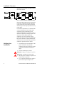
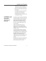
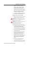
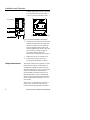
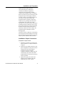
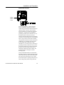
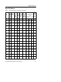
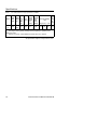
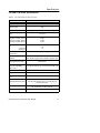
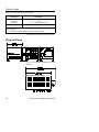
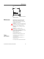
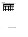
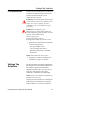
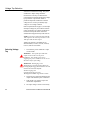
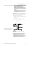
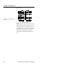
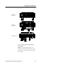
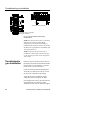
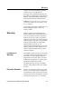
CC/CCS Power Conditioners User Instruction Manual
CC/CCS Power Conditioners
User Instruction Manual
IMPORTANT SAFETY INSTRUCTIONS
SAVE THESE INSTRUCTIONS.
Please read and save these instructions. This manual contains important
instructions for the Power Conditioner. Follow these instructions during the
unpacking, installation and maintenance of the Power Conditioner. If you have a
problem with the unit, please refer to this manual before calling ONEAC
Technical Services.
Licenses and Trademarks
ONEAC and Environmental Reference Ground are registered trademarks of
ONEAC Corporation. All other trademarks, product and corporate names are the
property of their respective owners.
ONEAC USA
27944 North Bradley Road
Libertyville, IL 60048-9700
USA
ONEAC EUROPE
George Curl Way
Southampton, Hampshire SO18 2RY
United Kingdom
Telephone: (847) 816-6000
Toll Free: (800) 327-8801
Facsimile: (847) 680-5124
Telephone: +44 (0) 2380 610311
Facsimile: +44 (0) 2380 649994
Entire contents copyright © 2006 ONEAC Corporation. All rights reserved. Reproduction in whole or
in part without permission is prohibited. All information subject to change without notice.
913-298 Rev. D
CC/CCS Power Conditioners User Instruction Manual
9/06
Introduction
Introduction
Thank you for selecting this ONEAC Power
Conditioner. ONEAC’s Power Conditioners
offer the most reliable protection available from
the harmful effects of electrical line
disturbances for your computing and
communications equipment.
ONEAC’s ISO 9001 certification represents our
commitment to building world-class products.
We take pride in every unit that leaves our
manufacturing facility.
Registering
Your Power
Conditioner
To register your Power Conditioner, complete
the warranty registration form on the ONEAC
website at www.oneac.com.
Technical
Support
ONEAC offers 24-hour technical support. To
contact ONEAC Technical Services:
• North America: (800) 327-8801 (opt. 3)
or (847) 816-6000 (opt. 3)
• Europe: +44 (0) 2380 610311
• email: [email protected].
NOTE: All calls received before 7 a.m. or after
7p.m. Central Standard Time are forwarded to a
cell phone. An ONEAC Technical Support
Representative will return your call within one
half hour between 5 p.m. and 10 p.m. Central
Standard Time. Except for emergencies, calls
received between 10 p.m. and 7 a.m. will be
returned during normal business hours.
Please check with ONEAC Technical Services
before attempting to repair or return any
ONEAC product. If an ONEAC unit needs
repair or replacement, ONEAC Technical
Services issues a Return Material Authorization
(RMA) number along with instructions on how
to return the unit.
WARNING: Dangerous voltages are present
within this unit. There are no user serviceable
parts within this unit; therefore, any repairs or
modifications may result in out-of-warranty
repair charges, unsafe electrical conditions, or
CC/CCS Power Conditioner User Manual
1
Installation Overview
violation of electrical code.
WARNUNG: Dieses
Leistungsanpassungsgerät führt
lebensgefährliche Spannung.
Stromschlaggefahr! Bitte beachten Sie die in
Ihrem Land geltenden Vorschriften über die
Verdrahtung und Beschaltung.
What Equipment
Needs Power
Conditioning?
Only your electronic based equipment requires
conditioned power. Fans, air conditioners and
motors do not require power conditioning.
Placing fans, air conditioners, motors or other
noise generators between the conditioner and
the electronics introduces electrical interference
into the already conditioned power. In order to
minimize electrical noise, each piece of
equipment should be individually wired back to
the output of the ONEAC power conditioner.
Sizing Information
The rating label of your ONEAC power
conditioner lists the model’s current rating,
nominal input and output voltage and serial
number. The combined steady state RMS
current draw of all your equipment must not
exceed the power conditioner’s output current
rating.
Installation
Overview
NOTE: Only qualified electricians should
install an ONEAC power conditioner. Follow
the U.S. National Electrical Code®, local codes,
good wiring practice and this User Manual.
1. Unpack the power conditioner (see
Unpacking and Placement on page 5).
2. Move the POWER CONDITIONER to the
installation location.
3. Connect the input plug or conduit. On
hardwire models, use a equipment
grounding conductor that is equal or larger
than the current carrying conductors (see
Input Connections on page 6).
4. Turn on the power feed to the input.
2
CC/CCS Power Conditioner User Manual
Installation Overview
5. Turn on the input circuit breaker.
6. Verify the correct operation of the power
conditioner (see Verifying Your
Installation on page 4).
7. Turn off the input circuit breaker. Connect
your equipment to the output (see Output
Connections on page 8). On hardwire
units, the use steel or flexible wall conduit
with a continuous copper ground is
recommended.
8. Turn on the input circuit breaker.
9. Turn on your equipment.
10. Start normal operation of your system.
Important
Installation
Guidelines
Only qualified electricians should install or
retrofit this ONEAC power conditioner.
WARNING: This power conditioner contains
dangerous voltages. Accidental contact can
result in serious electrical shock. Always follow
the US National Electrical Code or your local
electrical codes and good wiring practice.
WARNUNG: Dieses
Leistungsanpassungsgerät führt
lebensgefährliche Spannung.
Stromschlaggefahr! Bitte beachten Sie die in
Ihrem Land geltenden Vorschriften über die
Verdrahtung und Beschaltung.
This power conditioner is a single phase unit.
The secondary is wired as a single phase or in
some models, as a split phase output
configuration as shown below.
The input requires an equipment grounding
conductor connection. The use of steel or
CC/CCS Power Conditioner User Manual
3
Installation Overview
flexible steel wall conduit is strongly preferred
for hardwire models.
Fig. 1: CC and CCS Power Conditioner Wiring
Physically separate the input power connections
to the power conditioner from the equipment
power connections on the output. Data cables
should be kept as far away as possible from any
power cables.
For maximum performance, use shielded cable
or steel or flexible steel wall conduit with a
continuous copper ground between your
equipment and the power conditioner. Always
include an equipment grounding conductor for
each circuit on the output of the power
conditioner. Do not use extension cords or
power strips. Do not connect your equipment to
the power conditioner’s output until the input
connections have been made and proper power
conditioner operation has been verified.
Verifying Your
Installation
1. Turn OFF the input circuit breaker on the
power conditioner. Verify that the
installation follows the guidelines outlined
in Important Installation Guidelines on
page 3.
2. Turn ON the main power source.
WARNING: Dangerous voltages are present.
WARNUNG: Stromführend. Ebensgefahr!
3. Place the power conditioner’s input circuit
breaker in the ON position.
4. Use a voltmeter to determine if voltage is
present at the input and output. The
4
CC/CCS Power Conditioner User Manual
Installation and Operation
ONEAC power conditioner’s output
voltage may run a few volts higher than the
rated value until the load is switched on.
5. If there is power at the input with no power
at the output;
• Turn OFF the main input circuit breaker.
• Turn OFF the main power source
supplying the power conditioner.
• Follow the procedure in Troubleshooting
an Installation on page 26.
Installation and
Operation
Unpacking and
Placement
Your ONEAC power conditioner is delivered in
a protective package. Upon arrival, inspect the
unit and the package for signs of damage. If
damage is detected, immediately contact the
freight company and ONEAC Technical
Services. You can reach ONEAC Technical
Services at 1-800-327-8801, option 3 or at
1-847-816-6000.
ONEAC recommends that your power
conditioner be left in the package during
handling. Remove the conditioner from the
package once it is as close as possible to its final
installation location.
The actual physical placement of the power
conditioner should be as close as possible to
your equipment. The power conditioner should
be installed inside the room containing your
equipment. Allow at least 2 inches (5.0 cm)
around all sides of the ONEAC power
conditioner. Do not allow the conditioner to be
installed where direct contact with water is
possible.
Once the location of your power conditioner has
been determined, carefully remove the unit
from the package and put it into place.
CC/CCS Power Conditioner User Manual
5
Installation and Operation
Input Connections
The input connection for standard models is
supplied as a NEMA plug on the end of a cord.
Some models are available with a hardwire
input connection. Hardwire models have a 1/2”
(13 mm) conduit connection with internal
terminal blocks enclosed within an attached
wiring box. An additional hardwire version is
available that utilizes a flat conduit landing
plate attached to the rear of the unit that will
accept
1/2 or 3/4 inch conduit.
Your ONEAC cord-connected, CC and CCS
Series power conditioners will meet your power
conditioning requirements without the need for
special grounds. Since the cord-connected
power conditioner is considered as utilization
equipment, a connection to the equipment
grounding conductor that conforms to the U.S.
National Electrical Code and your local
electrical codes through the input cord and plug
is all that is necessary. However, for hardwired
units or if you wish to connect the secondary
side grounded conductor (neutral) of the power
conditioner to a grounding electrode system
(local building steel, water pipes, made
electrodes, etc.) you can do so by connecting a
grounding electrode conductor to the #10-32 x
3/4 inch stud referred to as the Environmental
Reference Ground®. This pressed-in stud is
electrically referenced to the secondary side
grounded conductor through an internal
bonding jumper.
Installation: Input Connections
Cord-connected models
1. Use a voltmeter to determine if voltage is
present in the branch circuit receptacle and
confirm that it is the same value as
specified on the power conditioner’s rating
label. The receptacle should meet the
requirements of the U.S. National
6
CC/CCS Power Conditioner User Manual
Installation and Operation
Electrical Code and any local codes.
2. With the ON/OFF switch in the OFF
position, plug the conditioner into the
receptacle at the power conditioner’s
desired location. The conditioner should
be as close as possible to your equipment.
3. Follow the procedure in the section
Verifying Your Installation on page 4.
4. Turn the power conditioner OFF and refer
to Installation: Output Connections.
Hardwire input connected models
1. Wire in accordance with the U.S. National
Electrical Code and your local codes.
WARNING: Turn off the main power source
supplying the power conditioner at the service
disconnect before proceeding.
WARNUNG: Vor dem nächsten Arbeitsschritt
muß die Hauptnetzversorgung zum
Leistungsanpassungsgerät am
Wartungstrennschalter abgeschaltet werden.
2. For Model CCxx48 units, remove the unit
cover to expose the input terminal
connections. For all other CC and CCS
Series, remove the cover on the rear panel
to expose the input terminal connections.
3. Place the input conduit through the bottom
or side knockout hole.
4. Connect the input equipment grounding
conductor to the terminal block (G).
Heavy gauge wire, equal to or larger in
diameter than the power carrying
conductors should be used to connect this
safety ground. It is recommended that
ground be wired back to the service
ground.
5. Do not rely on the conduit alone for
connection to ground. ONEAC
discourages the down sizing of grounding
conductors as allowed by various codes. If
CC/CCS Power Conditioner User Manual
7
Installation and Operation
in doubt regarding wire sizing, consult the
U.S. National Electrical Code, Table
310-16, or your local electrical codes.
CCxx48 Series
All Other CC and CCS Series - Hardwire
Fig. 2: CC and CCS Hardwire Connections
6. Connect the input phase wires to the input
terminal block. Separate the input power
cable to the ONEAC power conditioner
from the equipment power cable. Data
cables should be kept as far away from any
power cables as possible. Torque all
connections. Refer to the torque
specifications in Maintenance on page 19.
7. Replace the unit or rear terminal cover.
8. Follow the procedure in the section
Verifying Your Installation on page 4.
Output Connections
The output connections are supplied as various
NEMA style receptacles. Some models are
available with a hardwire output connection.
Hardwire models have a 1/2” (13 mm) conduit
connection with internal terminal blocks
enclosed within an attached wiring box. An
additional hardwire version is available that
utilizes a flat conduit landing plate attached to
the rear of the unit that will accept 1/2 or 3/4
inch conduit.
Your ONEAC cord-connected, CC and CCS
Series, power conditioners will meet your
power conditioning requirements without the
8
CC/CCS Power Conditioner User Manual
Installation and Operation
need for special grounds. Since the
cord-connected power conditioner is
considered as utilization equipment, a
connection to the equipment grounding
conductor that conforms to the U.S. National
Electrical Code and your local electrical codes
through the input cord and plug is all that is
necessary. However, for hardwired units or if
you wish to connect the secondary side
grounded conductor (neutral) of the power
conditioner to a grounding electrode system
(local building steel, water pipes, made
electrodes, etc.) you can do so by connecting a
grounding electrode conductor to the #10-32 x
3/4 inch stud referred to as the Environmental
Reference Ground. This pressed-in stud is
electrically referenced to the secondary side
grounded conductor through an internal
bonding jumper.
The ONEAC power conditioner circuit breaker
may be used as a central ON/OFF power switch.
Some models have fused outputs to protect the
ONEAC power conditioner from overload.
Installation: Output Connections
Receptacle output models
1. Follow the procedure for connecting the
input connections, see Input Connections
on page 6.
2. Each power run should be unique to each
piece of equipment in the system. The use
of temporary power taps should be
avoided. Even the use of duplex
receptacles should be avoided in the case
of electrically noisy loads. Data cables
should be kept as far away from any power
cables as possible.
3. Separate the input power cable to the
ONEAC power conditioner from the
equipment power cable. ONEAC
CC/CCS Power Conditioner User Manual
9
Installation and Operation
recommends that power runs on the output
of the conditioner be as short as possible,
with a maximum length of 50 feet (15 m).
4. Use wire sizes as recommended by the
National Electrical Code for lengths up to
25 feet (7.6m). For lengths from 30 feet
(9.1m) up to 50 feet (15.2m) increase the
NEC recommendations, for 60ºC
insulation, by 2 wire sizes (i.e. 10 gauge
rather than 12 gauge).
5. Torque all connections. Refer to the torque
specifications in Maintenance on page 19.
6. Make sure there is an equipment grounding
conductor connected between the
receptacle on the ONEAC power
conditioner output and your equipment.
7. Turn OFF the ONEAC power conditioner
circuit breaker and your equipment.
8. Plug your equipment into the appropriate
receptacle on the ONEAC power
conditioner. The power conditioner should
be as close as possible to your equipment.
9. Turn ON the ONEAC power conditioner
and then your equipment.
10. Begin normal operation of your
equipment.
Hardwire output connected models
1. Follow the procedure for connecting the
input connections, see Input Connections
on page 6.
2. Follow the U.S. National Electrical Code
and your local codes.
WARNING: Turn off the main power source
supplying the power conditioner at the service
disconnect before proceeding.
WARNUNG: Vor dem nächsten Arbeitsschritt
muß die Hauptnetzversorgung zum
Leistungsanpassungsgerät am
Wartungstrennschalter abgeschaltet werden.
10
CC/CCS Power Conditioner User Manual
Installation and Operation
3. Remove the rear terminal box cover or rear
conduit landing plate to expose the output
terminal connections.
4. Each power run should be unique to each
piece of equipment in the system. The use
of temporary power taps should be
avoided. Even the use of duplex
receptacles should be avoided in the case
of electrically noisy loads. Data cables
should be kept as far away from any power
cables as possible.
5. ONEAC recommends that power runs on
the output of the conditioner be as short as
possible, with a maximum length of 50
feet (15 m). Separate the input power cable
to the ONEAC power conditioner from the
equipment power cable.
6. Use wire sizes as recommended by the
U.S. National Electrical Code for lengths
up to 25 feet (7.6m). For lengths from 30
feet (9.1m) up to 50 feet (15.2m) increase
the NEC recommendations, for 60ºC
insulation, by 2 wire sizes (i.e. 10 gauge
rather than 12 gauge).
7. Place the output conduit through the side
1/2 inch (13 mm) conduit knockout of the
wiring box version or through the 1/2 or
3/4 inch conduit knockout in the flat
conduit landing plate. Use steel or flexible
steel wall conduit with a continuous
copper ground. This will limit any outside
interference and help to insure proper
system performance.
8. Connect the output ground to the terminal
block (G). Heavy gauge wire, equal to or
larger in diameter than the power carrying
conductors should be used to connect this
safety ground. Always include a ground
wire for each output circuit.
9. Do not rely on the conduit alone for
CC/CCS Power Conditioner User Manual
11
Installation and Operation
connection to ground. ONEAC
discourages the down sizing of grounding
conductors as allowed by various codes. If
in doubt regarding wire size, consult the
U.S. National Electrical Code, Table
310-16, or your local Electrical Codes.
10. Connect the output phase wires to the
output terminal block. Separate the input
power cable to the ONEAC power
conditioner from the equipment power
cable. Data cables should be kept as far
away from any power cables as possible.
11. Torque all connections. Refer to the torque
specifications in Maintenance on page 19.
Replace the rear terminal box cover or
conduit landing plate and unit cover.
12. Turn ON the ONEAC power conditioner
and then your equipment.
13. Begin normal operation of your
equipment.
Output fuses
Output fuses are located above the conditioner’s
receptacles or hardwire terminal connections.
Refer to Fuse Replacement on page 21 for
details on fuse replacement.
Use of the Environmental
12
CC/CCS Power Conditioner User Manual
Installation and Operation
Reference Ground
Environmental Reference
Ground
Your cord-connected, CC and CCS Series,
power conditioners will meet your power
conditioning requirements without the need for
special grounds. Since the cord-connected
power conditioner is considered as utilization
equipment, a connection to the equipment
grounding conductor that conforms to the U.S.
National Electrical Code and your local
electrical codes through the input cord and plug
is all that is necessary. However, for hardwired
units or if you wish to connect the secondary
side grounded conductor (neutral) of the power
conditioner to a grounding electrode system
(local building steel, water pipes, made
electrodes, etc.) you can do so by connecting a
grounding electrode conductor to the #10-32 x
3/4 inch stud referred to as the Environmental
Reference Ground. This pressed-in stud is
electrically referenced to the secondary side
grounded conductor through an internal
bonding jumper.
The Environmental Reference Ground offers
the ability to achieve a common point to ground
static control devices such as floor mats, table
mats, static-free work benches, or any other
devices that require a separate ground point. To
achieve this ground, remove the ground nut
CC/CCS Power Conditioner User Manual
13
Installation and Operation
from the environmental ground stud, attach the
ground cord connector of the static control
device, etc. (user provided) and reinstall and
tighten the ground nut.
14
CC/CCS Power Conditioner User Manual
Specifications
Specifications
Table 1. CC and CCS Series Specification by Model
Model
CC1128
Outpu
t
Input Output
Curre
Volta Voltage
nt
ge (V)
(V)
Max
(A)
Freq
(Hz)
1 kHz
Thermal
Forward Dissipati
Transfer
on at
Impedan
80%
ce
Load *
(Ohms) (BTU/hr)
Overload Capability
** (A)
0.5cyle1 sec
5 sec
Appro
x
Weig
ht
(lbs)
120
120
24
60
<1.3
<360
500
125
60
78
CC2333 208
240/
120
13.8
60
<3.3
<450
340
85
40
97
CC2338 240
240/
120
16
60
<3.7
<525
340
85
40
97
CC2350 208
240/
120
20.8
60
<2.1
<680
500
125
60
120
CC2357 240
240/
120
24
60
<2.5
<785
500
125
60
120
CCS112
120
8
120
24
50/60
<1.3
<295
500
125
60
93
CCS114
120
8
120
40
50/60
<0.75
<490
800
200
95
115
CCS115
120
7
120
48
50/60
<0.75
<980
1000
250
120
115
CCS21
28
240
120
24
50/60
<5.0
<295
260
65
30
96
CCS21
48
240
120
40
50/60
<3.0
<490
440
110
50
115
CCS21
57
240
120
48
50/60
<3.0
<980
500
125
60
115
CCS22
28
240
240
12
50/60
<5.0
<295
260
65
30
96
CCS22
48
240
240
20
50/60
<3.0
<490
440
110
50
115
CCS22
57
240
240
24
50/60
<3.0
<980
500
125
60
115
CCS23
28
240
240/
120
12
50/60
<5.0
<295
260
65
30
96
CCS23
48
240
240/
120
20
50/60
<3.0
<490
440
110
50
115
CC/CCS Power Conditioner User Manual
15
Specifications
Table 1. CC and CCS Series Specification by Model
Model
CCS23
57
Outpu
t
Input Output
Curre
Volta Voltage
nt
ge (V)
(V)
Max
(A)
Freq
(Hz)
240/
120
50/60
240
24
1 kHz
Thermal
Forward Dissipati
Transfer
on at
Impedan
80%
ce
Load *
(Ohms) (BTU/hr)
<3.0
<980
Overload Capability
** (A)
0.5cyle1 sec
500
125
5 sec
60
Appro
x
Weig
ht
(lbs)
115
*
BTU/hr is based on Watt loss times 3.41.
** Load surge current typically tolerated without degradation. Hardwired units
slightly less inrush
capacity (0.5 cycle), consult ONEAC Technical Services, if required.
All specifications subject to change without notice.
16
CC/CCS Power Conditioner User Manual
Specifications
CC AND CCS Series Specifications
Table 2. CC and CCS Series Specifications
Characteristic
Specification
Width (inches)
10.5 (26.7 cm) [alternate mounting - 12.7 (32.3 cm)]
Height (inches)
10.5 (27.7 cm) [reduced height construction – 9.7 (24.6
cm)]
Depth (inches) *
17.6 (44.7 cm)
Line Cord Length - Std
(feet)
10 (3.0 m)
RF 50 Ohm Insertion Loss
400 kHz to 4 MHz (typical)
100 kHz to 10 MHz (typical)
30 kHz to 30 MHz (typical)
50 dB
40 dB
30 dB
Efficiency at Rated Load
(%):
CC Series
CCS Series
Load Power Factor Range
(Crest Factor)
> 95
> 97
0.3 leading to 0.3 lagging
Surge Voltage Withstand
Capability
ANSI/IEEE C62.41 Category A&B, 6 kV/ 200A,
500A,100 kHz ringwave and 6 kV/3000 A impulse wave.
Normal & Common Mode
Clamping Response Time
Instantaneous
Surge Voltage Let-Through
(max.) 6kv ANSI/IEEE
C62.41 Cat. A
< 10V Normal mode (L-N), < 0.5V Common mode (L-G)
Distortion
< 1% THD added into a resistive load
Load Regulation
± 2%
Load Regulation Response
Time
< 2 msec for a 50% change in load
Interruption Response Time
Output voltage will track input voltage in less than 2
msec at power-off and power-on for a single-cycle
asynchronous notch.
Ambient Operation
10,000 ft (3,000 meters) max. elevation, 0-95 % humidity
non-condensing, 32-104°F (0-40°C)
Cooling
CC/CCS Power Conditioner User Manual
Convection
17
Physical Views
Table 2. CC and CCS Series Specifications
Characteristic
Approvals **
CC Series
CCS Series
Warranty
Specification
UL, cUL
UL, cUL, CE (on selected units)
5-year materials and workmanship
* Hardwire models with wiring box, add 2.7 inches (6.9 cm) to depth. See Physical
Views on page 18.
** UL1012 with CE mark assessed against IEC 60950 (UL 60950)
All specifications subject to change without notice.
Physical Views
Fig. 3: CC & CCS Power Conditioner Front and
Rear View
18
CC/CCS Power Conditioner User Manual
Maintenance
Fig. 4: CC & CCS Power Conditioner Right Side
View
12.7
(32.3 cm)
9.7
(24.6 cm)
Fig. 5: CC & CCS Power Conditioner Reduced
Height Construction
Maintenance
Maintaining the correct operation of your
ONEAC Power Conditioner is limited to
annually checking the operating voltage and
torquing all the connections.
WARNING: Turn off the input and main output
circuit breakers on the power conditioner. Turn
off the power source supplying the power
conditioner at the service disconnect before
proceeding.
WARNUNG: Die Eingangs- und
Hauptausgangs-Leistungsschutzschalter am
Leistungsanpassungsgerät abschalten. Vor dem
nächsten Arbeitsschritt muß die
Stromversorgung zum
Leistungsanpassungsgerät am
Wartungstrennschalter abgeschaltet werden.
Torque
Specifications
Circuit Breakers torque specification - on
circuit breaker label.
Terminal Blocks torque specification - on
terminal block label.
For all other fasteners, follow the chart below.
CC/CCS Power Conditioner User Manual
19
Maintenance
Table 3. Recommended Safe Working Torque Specifications
Bolt or Screw Size
20
Steel
inch-lbs
Nm
Brass
inch-lbs
Nm
3/8”
9 mm
21 ft-lbs
28
16 ft-lbs
21
5/16”
8 mm
138
15
107
12
1 /4”
6 mm
79
9
62
7
#10
(M5)
24
2.5
19
2
#8
(M4)
21
2
16
1.5
#6
(M3.5)
10
1
8
1
#4
(M3)
5.5
0.5
4.3
0.5
CC/CCS Power Conditioner User Manual
Voltage Tap Selection
Fuse Replacement
Output fuses are located above the conditioner's
receptacles or hardwire terminal connections.
The fuses protect the ONEAC power
conditioner from overload.
WARNING: Turn off the input and main output
circuit breakers on the power conditioner. Turn
off the power source supplying the power
conditioner at the service disconnect before
proceeding.
WARNUNG: Die Eingangs- und
Hauptausgangs-Leistungsschutzschalter am
Leistungsanpassungsgerät abschalten. Vor dem
nächsten Arbeitsschritt muß die
Stromversorgung zum
Leistungsanpassungsgerät am
Wartungstrennschalter abgeschaltet werden.
1. If a fuse blows, replace the blown fuse with
the same rating and type.
Fuse type: Midget (5AG).
Use a time delay fuse such as:
Bussmann FNW Series or Littelfuse
FLM Series
NOTE: Some models do not have fuses.
2. Follow the procedure in Verifying Your
Installation on page 4, as required.
Voltage Tap
Selection
Tap selection allows a permanent adjustment to
the voltage level. If the nominal output level is
not within the equipment manufacturer’s
suggested operating range, you can move the
power tap on the primary of the power
conditioner’s transformer as an adjustment.
NOTE: Tap selection should be completed by a
qualified electrician, only.
The purpose of tap selection is to configure the
input of the power conditioner to accept the
desired voltage or to correct for steady state
CC/CCS Power Conditioner User Manual
21
Voltage Tap Selection
variances in nominal line voltage. The power
conditioner’s output voltage should be
monitored for a few days to determine the
normal output level before adjusting the voltage
by tap selection. Tap selection allows a
permanent adjust the conditioner's nominal
voltage level to correct a persistently high
voltage or low voltage condition.
Refer to Specifications on page 15, for the input
and output voltage for your model of ONEAC
power conditioner. The voltage specifications
as stated in the Specifications section are
standard when shipped directly from ONEAC.
NOTE: To operate at 208 Volts input and 208
Volts output use the same tap selection as 240
Volts input and 240 Volts output.
Voltage tap selection is available only on
selected models; CC2333, CC2338, CC2350,
CC2357, and all CCS models.
Selecting Voltage
Tap
1. Turn OFF the power conditioner’s input
circuit breaker.
WARNING: Turn off the input and main
output circuit breakers on the power
conditioner. Turn off the power source
supplying the power conditioner at the service
disconnect before proceeding.
WARNUNG: Die Eingangs- und
Hauptausgangs-Leistungsschutzschalter am
Leistungsanpassungsgerät abschalten. Vor dem
nächsten Arbeitsschritt muß die
Stromversorgung zum
Leistungsanpassungsgerät am
Wartungstrennschalter abgeschaltet werden.
2. Disconnect any equipment attached to the
output of the ONEAC power conditioner.
3. Take off the cover panel to expose the
transformer compartment
4. The input voltage is raised or lowered by
22
CC/CCS Power Conditioner User Manual
Voltage Tap Selection
moving the winding jumper lead(s) on the
primary side of the transformer.
Refer to the transformer schematic in Fig.
6 for the CC2333, CC2338, CC2350, and
CC2357.
Refer to the transformer schematic in Fig.
7 and terminal drawing in Fig. 8 for CCS
Series Products.
NOTE: To operate at 208 Volts input and 208
Volts output use the same tap selection as 240
Volts input and 240 Volts output.
5. Torque all connections as per Maintenance
on page 19.
6. Re-install the cover panel.
7. Mark any nominal voltage changes on or
near the rating nameplate.
8. Follow the procedure in Section 2.2,
Verifying Your Installation.
Transformer Schematic for Models
CC2333, CC2338, CC2350 and
Fig. 6: CC Power Conditioner Transformer
Schematic
NOTE: The centered tapped secondary coil
output of these CC series power conditioners
can be wired from the factory as either
grounded 240 V (terminal 5 ground referenced)
or 240/120 split phase (terminal 6 ground
CC/CCS Power Conditioner User Manual
23
Voltage Tap Selection
referenced).
Transformer Schematic for all CCS
Models.
Fig. 7: CCS Transformer Schematic
NOTE: The dual wound secondary coil output
of the CCS Series power conditioners can be
wired in parallel as a grounded 120 V, in series
as grounded 240 V or in series and center-tap
grounded as 240/120 split phase. Both primary
and secondary windings are connected to
terminal blocks and labelled as indicated in
Fig. 7
24
CC/CCS Power Conditioner User Manual
Voltage Tap Selection
CCS Series:
120 V Primary
CCS Series:
240 V Primary
PB2
Black
CCS Series: 208 V
Fig. 8: CCS Series Primary Terminal Block
Configurations
NOTE: To operate the CCS Series power
conditioner at 208 V input with 208 V output
use the same tap selection as 240 V input and
240 V output.
CC/CCS Power Conditioner User Manual
25
Troubleshooting an Installation
CCS Series: 120 V Secondary
CCS Series: 240 V or 240/120 V
Split Phase Secondary
Fig. 9: CCS Terminal Block Secondary
Configurations
NOTE: For the CCS Series 240 V or 240/120 V
Split Phase Secondary Terminal Block
Configuration, Neutral-Ground bonding is
completed at the capacitor connections of either
the RED (240 V grounded) or the WHITE (240/
120 V Split phase) wire.
NOTE: To operate the CCS Series power
conditioner at 208 V input with 208 V output,
use the same tap selection as 240 V input and
240 V output.
Troubleshootin
g an Installation
If there is power at the input with no power at
the output, turn OFF the circuit breaker and then
the input power to the conditioner - the main
power source or service disconnect.
Check the values specified on the nameplate.
Verify that your main power source is correct
for the power conditioners input voltage.
Verify that the power conditioner’s input
voltage has not been changed in the field.
If everything seems correct, disconnect the line
and ground input wires and then contact
Technical Services. Refer to Technical Support
26
CC/CCS Power Conditioner User Manual
Warranty
on page 1 for the correct telephone number.
Technical Services will ask you for a
description of the problem and will help solve
the problem over the telephone or issue a Return
Material Authorization (RMA) number along
with instructions on how to return the UPS.
NOTE:Please supply the service representative
with the part number and serial number of the
power conditioner.
Always check with ONEAC Technical Services
before attempting to repair or return any
ONEAC product.
Warranty
ONEAC products are warranted free from
defects in materials and workmanship for five
years. This warranty is limited to repairing or
replacing, at ONEAC’s option, any defective
component, circuit board, or module contained
within the product only when it is returned with
an ONEAC Return Material Authorization
(RMA) number to ONEAC or to an
ONEAC-designated repair facility. In all cases,
shipping charges to and from ONEAC or the
ONEAC-designated repair facility are at the
customer’s expense.
Limitations of
Warranty
This limited warranty does not cover any losses
or damage resulting from shipment to or from
the customer, or from improper installation,
inappropriate environment, abuse, or from an
modifications, adjustments, or repair by other
than ONEAC-authorized personnel.
For full details of the warranty, see ONEAC
Warranty, Policy and Procedures (part number
955-053).
Exclusive Remedies
Except as set forth herein and except as to title,
there are no warranties, express or implied, or
any affirmations of fact or promises by ONEAC
for the products, their merchantability, or fitness
for any particular purpose. In no event shall
CC/CCS Power Conditioner User Manual
27
Warranty
ONEAC be liable for lost profits, goodwill, or
any other special or consequential damages.
Return Procedure
28
To return a power conditioner, contact ONEAC
for a Return Material Authorization (RMA)
number. This number must be marked on the
shipping carton and packing slip of the unit
returned. The customer is responsible for repair
charges for damages incurred in shipment that
result from inadequate or improper packing of
the product.
CC/CCS Power Conditioner User Manual