1
SERVICE MANUAL
Color Inkjet Printer
EPSON Stylus Photo R1900/R2880/R2000
Confidential
SEIJ07010
Notice:
All rights reserved. No part of this manual may be reproduced, stored in a retrieval system, or transmitted in any form or by any means, electronic, mechanical,
photocopying, recording, or otherwise, without the prior written permission of SEIKO EPSON CORPORATION.
The contents of this manual are subject to change without notice.
All effort have been made to ensure the accuracy of the contents of this manual. However, should any errors be detected, SEIKO EPSON would greatly appreciate being
informed of them.
The above not withstanding SEIKO EPSON CORPORATION can assume no responsibility for any errors in this manual or the consequences thereof.
EPSON is a registered trademark of SEIKO EPSON CORPORATION.
General Notice:
Other product names used herein are for identification purpose only and may be trademarks or registered trademarks of their
respective owners. EPSON disclaims any and all rights in those marks.
Copyright © 2011
SEIKO EPSON CORPORATION.
Imaging & Information CS Quality Assurance Department
Confidential
PRECAUTIONS
Precautionary notations throughout the text are categorized relative to 1)Personal injury and 2) damage to equipment.
DANGER
Signals a precaution which, if ignored, could result in serious or fatal personal injury. Great caution should be exercised in performing procedures preceded by
DANGER Headings.
WARNING
Signals a precaution which, if ignored, could result in damage to equipment.
The precautionary measures itemized below should always be observed when performing repair/maintenance procedures.
DANGER
1.
2.
3.
4.
ALWAYS DISCONNECT THE PRODUCT FROM THE POWER SOURCE AND PERIPHERAL DEVICES PERFORMING ANY MAINTENANCE OR REPAIR
PROCEDURES.
NO WORK SHOULD BE PERFORMED ON THE UNIT BY PERSONS UNFAMILIAR WITH BASIC SAFETY MEASURES AS DICTATED FOR ALL ELECTRONICS
TECHNICIANS IN THEIR LINE OF WORK.
WHEN PERFORMING TESTING AS DICTATED WITHIN THIS MANUAL, DO NOT CONNECT THE UNIT TO A POWER SOURCE UNTIL INSTRUCTED TO DO
SO. WHEN THE POWER SUPPLY CABLE MUST BE CONNECTED, USE EXTREME CAUTION IN WORKING ON POWER SUPPLY AND OTHER ELECTRONIC
COMPONENTS.
WHEN DISASSEMBLING OR ASSEMBLING A PRODUCT, MAKE SURE TO WEAR GLOVES TO AVOID INJURIER FROM METAL PARTS WITH SHARP EDGES.
WARNING
1.
2.
3.
4.
5.
6.
REPAIRS ON EPSON PRODUCT SHOULD BE PERFORMED ONLY BY AN EPSON CERTIFIED REPAIR TECHNICIAN.
MAKE CERTAIN THAT THE SOURCE VOLTAGES IS THE SAME AS THE RATED VOLTAGE, LISTED ON THE SERIAL NUMBER/RATING PLATE. IF THE
EPSON PRODUCT HAS A PRIMARY AC RATING DIFFERENT FROM AVAILABLE POWER SOURCE, DO NOT CONNECT IT TO THE POWER SOURCE.
ALWAYS VERIFY THAT THE EPSON PRODUCT HAS BEEN DISCONNECTED FROM THE POWER SOURCE BEFORE REMOVING OR REPLACING PRINTED
CIRCUIT BOARDS AND/OR INDIVIDUAL CHIPS.
IN ORDER TO PROTECT SENSITIVE MICROPROCESSORS AND CIRCUITRY, USE STATIC DISCHARGE EQUIPMENT, SUCH AS ANTI-STATIC WRIST
STRAPS, WHEN ACCESSING INTERNAL COMPONENTS.
REPLACE MALFUNCTIONING COMPONENTS ONLY WITH THOSE COMPONENTS BY THE MANUFACTURE; INTRODUCTION OF SECOND-SOURCE ICs OR
OTHER NON-APPROVED COMPONENTS MAY DAMAGE THE PRODUCT AND VOID ANY APPLICABLE EPSON WARRANTY.
WHEN USING COMPRESSED AIR PRODUCTS; SUCH AS AIR DUSTER, FOR CLEANING DURING REPAIR AND MAINTENANCE, THE USE OF SUCH
PRODUCTS CONTAINING FLAMMABLE GAS IS PROHIBITED.
Confidential
About This Manual
This manual describes basic functions, theory of electrical and mechanical operations, maintenance and repair procedures of the printer. The instructions and procedures included
herein are intended for the experienced repair technicians, and attention should be given to the precautions on the preceding page.
Manual Configuration
This manual consists of six chapters and Appendix.
CHAPTER 1.PRODUCT DESCRIPTIONS
Provides a general overview and specifications of the product.
CHAPTER 2.OPERATING PRINCIPLES
Describes the theory of electrical and mechanical operations of the
product.
CHAPTER 3.TROUBLESHOOTING
Describes the step-by-step procedures for the troubleshooting.
CHAPTER 4.DISASSEMBLY / ASSEMBLY
Describes the step-by-step procedures for disassembling and assembling
the product.
CHAPTER 5.ADJUSTMENT
Provides Epson-approved methods for adjustment.
CHAPTER 6.MAINTENANCE
Provides preventive maintenance procedures and the lists of Epsonapproved lubricants and adhesives required for servicing the product.
APPENDIX Provides the following additional information for reference:
• Connector pin assignments
Stylus Photo R2000
Provides information of Stylus Photo R2000
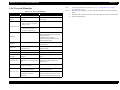
Symbols Used in this Manual
Various symbols are used throughout this manual either to provide additional
information on a specific topic or to warn of possible danger present during a
procedure or an action. Be aware of all symbols when they are used, and always read
NOTE, CAUTION, or WARNING messages.
Indicates an operating or maintenance procedure, practice or condition
that is necessary to keep the product’s quality.
Indicates an operating or maintenance procedure, practice, or condition
that, if not strictly observed, could result in damage to, or destruction of,
equipment.
May indicate an operating or maintenance procedure, practice or
condition that is necessary to accomplish a task efficiently. It may also
provide additional information that is related to a specific subject, or
comment on the results achieved through a previous action.
Indicates an operating or maintenance procedure, practice or condition
that, if not strictly observed, could result in injury or loss of life.
Indicates that a particular task must be carried out according to a certain
standard after disassembly and before re-assembly, otherwise the
quality of the components in question may be adversely affected.
Confidential
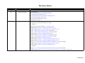
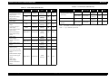
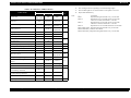
Revision Status
Revision
Date of Issue
Description
A
October 20, 2007
First Release
B
February 29, 2008
Revised Contents
4.4.4 Lower Housing / Printer Mechanism (p96)
Disassembly procedure is revised.
4.4.8 Waste Ink Pad / Waste Ink Tube Left/Right (p110)
Description and figure are revised.
6.1.2.2 Maintenance Request (p163)
Description is revised.
C
April 25, 2008
Revised Contents
Descriptions about Stylus Photo R2880 are added.
Chapter 1
Descriptions have been added in 1.1.1 Features (p10).
Made changes in Table 1-1"Printer Specifications"(p 11).
Made changes in Table 1-2"Product No. of Ink Cartridges"(p 11).
Table 1-6"Print Mode (Color)"(p 14) has been added.
Table 1-7"Print Mode (Monochrome)"(p 15) has been added.
Made changes in Table 1-8"Supported Paper"(p 16).
Made changes in Table 1-9"Printing Area (Margins)"(p 20).
Table 1-10"Printing Area (Margins)"(p 20) has been added.
Made changes in Table 1-12"Device ID"(p 21).
Made changes in Table 1-13"Primary Power Specifications"(p 21).
Made changes in Table 1-17"Operation Button Functions"(p 24).
Figure 1-6, "Nozzle Check Pattern (Stylus Photo R2880)" (p 25) has been added.
Made changes in Table 1-18"Indicators (LEDs) Function"(p 26).
Made changes in Table 1-19"Errors & Remedies"(p 27).
Chapter 2
Figure 2-3, "Nozzle Arrangement (Stylus Photo R2880)" (p 30) has been added.
Made changes in Table 2-3"Nozzle Lines and the Corresponding Ink Color (Stylus Photo R2880)"(p 30).
Confidential
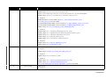
Revision
Date of Issue
C
April 25, 2008
Description
Chapter 3
Made changes in Table 3-1"List of Error Messages"(p 34).
Table 3-10"Troubleshooting of Ink Color Error (Stylus Photo R2880 only)"(p 48) has been added.
Made changes in Table 3-13"Troubleshooting of Maintenance Request"(p 50).
Chapter 4
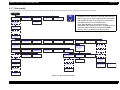
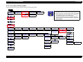
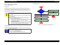
CHECK POINT" has been added in Figure 4-6, "Disassembly Flowchart" (p 75).
4.2.5 Panel Unit (p78) has been added.
"ADJUSTMENT REQUIRED" has been added in 4.2.7 Upper Housing / Printer Cover (p81)
"ADJUSTMENT REQUIRED" has been added in 4.3.3 High Voltage Module (p87)
Made changes in 4.4.4 Lower Housing / Printer Mechanism (p96).
Chapter 5
Made changes in 5.1.1 Servicing Adjustment Item List (p138).
Made changes in 5.1.2 Replacement Part-Based Adjustment Priorities (p142).
Made changes in 5.1.3 Required Adjustment Tools (p143).
Made changes in 5.2.2 PG Adjustment (p145).
Made changes in 5.2.4 Colorimetric Calibration (p153).
Chapter 6
Made changes in 6.1.2 Service Maintenance (p162).
Made changes in 6.1.3 Lubrication (p164).
D
December 18, 2009
Revised Contents
Chapter 1
Made changes in Table 1-10"Printing Area (Margins)"(p 20).
Chapter 4
Made changes in 4.4.6 ASF Assy (p106).
Chapter 5
Made changes in 5.1.1 Servicing Adjustment Item List (p138).
Made changes in 5.1.2 Required Adjustments (p141).
5.2.5 ASF Guide Roller LDs Position Adjustment (p159) has been added.
E
April 11, 2011
Added Chapter
Chapter 8
Confidential
EPSON Stylus Photo R1900/R2880/R2000
Revision E
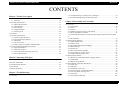
CONTENTS
Chapter 1 Product Description
3.1.1 Troubleshooting according to Error Messages .......................................... 34
3.1.2 Troubleshooting based on Observed Faults .............................................. 60
1.1 Product Description ............................................................................................. 10
1.1.1 Features ...................................................................................................... 10
1.2 Printing Specifications.........................................................................................
1.2.1 Basic Specifications ...................................................................................
1.2.2 Ink Cartridge ..............................................................................................
1.2.3 Print Mode .................................................................................................
1.2.4 Supported Paper .........................................................................................
1.2.5 Printing Area .............................................................................................
11
11
11
12
16
20
1.3 Interface............................................................................................................... 21
1.4 General Specifications.........................................................................................
1.4.1 Electrical Specifications ............................................................................
1.4.2 Environmental Conditions .........................................................................
1.4.3 Durability ...................................................................................................
1.4.4 Acoustic Noise ...........................................................................................
1.4.5 Safety Approvals (Safety standards/EMI) .................................................
21
21
22
22
22
22
1.5 Operation Buttons & Indicators (LEDs).............................................................. 23
1.5.1 Operation Buttons ...................................................................................... 23
1.5.2 Indicators (LEDs) ...................................................................................... 23
1.5.3 Operation Buttons & LEDs Functions ...................................................... 24
1.5.4 Errors & Remedies .................................................................................... 27
Chapter 2 Operating Principles
2.1 Overview ............................................................................................................. 29
2.2 Printer Mechanism............................................................................................... 29
2.3 Printhead Specifications ...................................................................................... 30
2.4 PG Setting............................................................................................................ 31
2.5 Motors & Sensors ................................................................................................ 32
Chapter 3 Troubleshooting
3.1 Overview ............................................................................................................. 34
Chapter 4 Disassembly And Assembly
4.1 Overview ............................................................................................................. 70
4.1.1 Precautions ................................................................................................ 70
4.1.2 Tools .......................................................................................................... 71
4.1.3 Screws ....................................................................................................... 71
4.1.4 Making a Special Tool for CSIC Board .................................................... 71
4.1.5 Work Completion Checklist ...................................................................... 72
4.1.6 Locking/Unlocking the Carriage and Opening/Closing the CDR Tray Base
73
4.1.7 Disassembly ............................................................................................... 75
4.2 Removing the Housings ......................................................................................
4.2.1 Paper Support Assy ...................................................................................
4.2.2 Stacker Assy ..............................................................................................
4.2.3 Front Decoration Plate Left/Right .............................................................
4.2.4 Rear Housing .............................................................................................
4.2.5 Panel Unit ..................................................................................................
4.2.6 Decoration Plate Left/Right .......................................................................
4.2.7 Upper Housing / Printer Cover ..................................................................
4.2.8 Upper Housing Support Assy ....................................................................
76
76
76
77
77
78
80
81
83
4.3 Removing the Boards ..........................................................................................
4.3.1 Board Assy (Main Board/Power Supply Board) .......................................
4.3.2 LED Board ................................................................................................
4.3.3 High Voltage Module ................................................................................
84
84
86
87
4.4 Disassembling the Printer Mechanism ................................................................ 89
4.4.1 APG Assy .................................................................................................. 89
4.4.2 CR Scale .................................................................................................... 90
4.4.3 Printhead / CSIC Assy ............................................................................... 92
4.4.4 Lower Housing / Printer Mechanism ........................................................ 96
4.4.5 Carriage Shaft / Carriage Unit ................................................................... 98
4.4.6 ASF Assy ................................................................................................. 106
4.4.7 Front Paper Guide Pad ............................................................................ 109
7
Confidential
EPSON Stylus Photo R1900/R2880/R2000
Revision E
4.4.8 Waste Ink Pad / Waste Ink Tube Left/Right ........................................... 110
4.4.9 Foot .......................................................................................................... 111
4.4.10 PictBridge Holder Assy ......................................................................... 111
4.4.11 Paper EJ Frame Assy / Front Cover / CDR Tray Base .......................... 112
4.4.12 CDR Release Lever Sub Assy ............................................................... 114
4.4.13 Ink System Unit ..................................................................................... 116
4.4.14 Front Paper Guide / Paper EJ Roller /
Front Paper Guide Pad Tray ............................................................................. 119
4.4.15 PF Roller Shaft ...................................................................................... 122
4.4.16 Release Holder Assy .............................................................................. 125
4.4.17 FLAG Release Assy .............................................................................. 126
4.4.18 Upper Paper Guide Assys ...................................................................... 127
4.5 Removing the Motors ........................................................................................
4.5.1 CR Motor .................................................................................................
4.5.2 PF Motor ..................................................................................................
4.5.3 ASF Motor ...............................................................................................
129
129
130
131
4.6 Removing the Sensors ....................................................................................... 132
4.6.1 CR Encoder ............................................................................................. 132
4.6.2 PF Encoder .............................................................................................. 132
4.6.3 Ink Mark Sensor / PW sensor .................................................................. 133
4.6.4 CDR Sensor ............................................................................................. 134
4.6.5 PE Sensor Holder .................................................................................... 135
4.6.6 Cover Open Sensor .................................................................................. 136
Chapter 5 Adjustment
5.1 Adjustment Items and Overview .......................................................................
5.1.1 Servicing Adjustment Item List ...............................................................
5.1.2 Required Adjustments .............................................................................
5.1.3 Required Adjustment Tools .....................................................................
138
138
141
143
5.2 Adjustment ........................................................................................................
5.2.1 PF Belt Tension Adjustment ...................................................................
5.2.2 PG Adjustment ........................................................................................
5.2.3 PF Roller Shaft Center Support Position Adjustment .............................
5.2.4 Colorimetric Calibration ..........................................................................
5.2.5 ASF Guide Roller LDs Position Adjustment ..........................................
144
144
145
149
153
159
6.1 Overview ...........................................................................................................
6.1.1 Cleaning ...................................................................................................
6.1.2 Service Maintenance ...............................................................................
6.1.3 Lubrication ..............................................................................................
162
162
162
164
Chapter 7 Appendix
7.1 Connector Summary.......................................................................................... 171
7.2 Exploded Diagram / Parts List .......................................................................... 171
Chapter 8 Stylus Photo R2000
8.1 Product Description ........................................................................................ 173
8.2 Features ............................................................................................................. 174
8.2.1 Casing specifications ............................................................................... 174
8.2.2 NetWork Interface ................................................................................... 175
8.2.3 Ink Cartridge ................................................................................ 177
8.2.4 Nozzle Configuration .............................................................................. 178
8.2.5 Ink Scrambling Sequence ........................................................................ 178
8.2.6 Operation Buttons & Indicators (LEDs) ................................................. 179
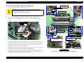
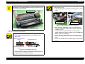
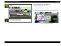
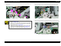
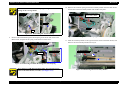
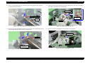
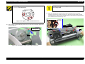
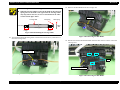
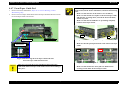
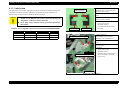
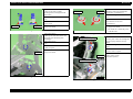
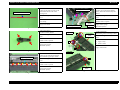
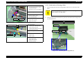
8.3 Disassembly....................................................................................................... 183
8.3.1 Summary ................................................................................................. 183
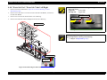
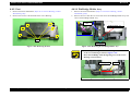
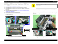
8.3.2 Procedure of Disassembly ....................................................................... 184
8.4 Adjustment ........................................................................................................
8.4.1 Summary .................................................................................................
8.4.2 Sevicing Adjusment Item List (For Stylus Photo R2000) .......................
8.4.3 Required Adjustments .............................................................................
8.4.4 Adjusment Procedure ..............................................................................
190
190
190
191
193
Chapter 6 Maintenance
8
Confidential
CHAPTER
1
PRODUCT DESCRIPTION
Confidential
EPSON Stylus Photo R1900/R2880/R2000
Revision E
1.1 Product Description
1.1.1 Features
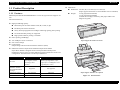
EPSON Stylus Photo R1900/R2880/R2000 is a color ink-jet printer that supports A3+
size.
The main features are;
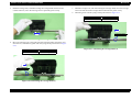
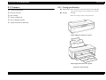
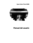
Dimensions
Dimensions: 616 mm (W) x 322 mm (D) x 214 mm (H)
(Paper support and stacker are closed. Rubber feet are included)
Weight:
12.2 kg (Stylus Photo R1900)
12.3 kg (Stylus Photo R2880)
(without ink cartridges, CDR Tray, Roll paper holders and
Single sheet guide)
High speed & High quality
Maximum print resolution: SMGA 5760 (H) x 1440 (V) dpi
F8 Mach print head are mounted.
Newly developed pigment ink cartridges enable high quality photo printing.
CD and DVD label printing are supported.
High-speed borderless printing is available.
Direct printing (PictBridge)
Two USB ports for PC connection
Paper Support & Stacker are Closed
New exterior design
Control panel
Simple design with four buttons and three indicators (LED).
Differences between Stylus Photo R1900 and Stylus Photo R2880
Stylus Photo R2880 is designed based on the Stylus Photo R1900 printer
mechanism, however, there are some differences between them such as ink color
configuration. The table below lists the major differences.
Item
Ink colors
Simultaneous
installation of Photo
Black and Matte Black
cartridges
Board paper printing
Print Mode
Product Description
Stylus Photo R1900
Photo Black, Matte Black,
Cyan, Magenta, Yellow,
Red, Orange, Gloss
Optimizer
Stylus Photo R2880
Photo Black, Matte Black, Light
Black, Light Light Black, Cyan,
Light Cyan, Vivid Magenta, Vivid
Light Magenta, Yellow
Supported
Not supported
Not supported
Supported
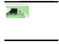
Paper Support & Stacker are Opened
4 modes
5 modes
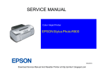
Figure 1-1. External View
Product Description
10
Confidential
EPSON Stylus Photo R1900/R2880/R2000
Revision E
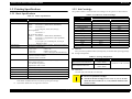
1.2 Printing Specifications
1.2.2 Ink Cartridge
1.2.1 Basic Specifications
The product numbers of the EPSON ink cartridges for this printer are shown below.
Table 1-2. Product No. of Ink Cartridges
Table 1-1. Printer Specifications
Item
Print method
On-demand ink jet
Nozzle configuration
Stylus Photo R1900
Black:
Color:
Print direction
Print resolution
Control code
Internal font
Input buffer size
180 nozzles x 2 (Photo Black, Matte Black)
180 nozzles x 5
(Cyan, Magenta, Yellow, Red, Orange)
Gross Optimizer:
180 nozzles x 1
Stylus Photo R2880
Black*1: 180 nozzles x 1 (Photo Black, Matte Black)
Gray:
180 nozzles x 2 (Light Black, Light Light Black)
Color:
180 nozzles x 5
(Cyan, Light Cyan, Vivid Magenta, Vivid Light
Magenta, Yellow)
Bi-directional minimum distance printing, unidirectional printing
Horizontal x Vertical (dpi)
• 360 x 180*2
• 1440 x 720
• 360 x 360
• SMGA 5760 x 1440
• 720 x 720
• 1440 x 1440 (Stylus Photo R2880 only)
• ESC/P Raster command
• ESC/P-R (RGB) command
• EPSON Remote command
Character code:Alphanumeric with expanded graphics (PC437)
ASCII, 20H to 7FH only
Font: EPSON original font
Alphanumeric font: Courier
Friction feed, using one ASF (Auto Sheet Feeder)
Paper path
2-way feed
Paper feed rates
170 msec (at 25.4 mm feed)
PF interval
Programmable in 0.01764 mm (1/1440 inch) steps
Note *1:
*2:
Stylus Photo R2880
T0961
T0968
T0967
T0969
T0962
T0965
-T0963
T0966
T0964
----
Shelf life
Two years from production date (if unopened), six months after opening package.
Storage Temperature
Table 1-3. Storage Temperature
Situation
When stored in individual boxes
When installed in main unit
Storage Temperature
-20 oC to 40 oC
(-4oF to 104oF)
-20 oC to 40 oC
(-4oF to 104oF)
Limit
1 month max. at 40 oC (104oF)
Dimension
12.7 mm (W) x 68 mm (D) x 47 mm (H)
C A U T IO N
Stylus Photo R2880 has only one slot for black ink cartridge. Switching between the
Photo Black and Matte Black can be made by replacing the cartridge.
Stylus Photo R2880 does not support the resolution.
Product Description
Stylus Photo R1900
T0871
T0878
--T0872
-T0873
--T0874
T0879
T0877
T0870
Photo Black
Matte Black
Light Black
Light Light Black
Cyan
Light Cyan
Magenta
Vivid Magenta
Vivid Light Magenta
Yellow
Orange
Red
Gloss Optimizer
T.B.D. Kbytes
Paper feed method
Code
Color
Specifications
Printing Specifications
The ink cartridge cannot be refilled.
Do not use expired ink cartridges.
The ink in the ink cartridge freezes at -16 °C (3.2 oF). It takes
about three hours under 25 °C (77oF) until the ink thaws and
becomes usable.
11
Confidential
EPSON Stylus Photo R1900/R2880/R2000
Revision E
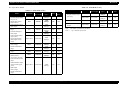
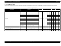
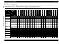
1.2.3 Print Mode
Table 1-4. Print Mode (Color)
Media
Print
Mode
Resolution
(H x V) dpi
Dot Size
(cps*)
Bi-d
Micro
Weave
• Archival Matte Paper (EAI)
• Enhanced Matte Paper (others)
Photo
1440x720
VSD2
(200cps)
ON
ON
Super
Photo
5760x1440
VSD3
(200cps)
ON
ON
Photo
1440x720
VSD2
(200cps)
ON
ON
Super
Photo
5760x1440
VSD3
(200cps)
ON
ON
• Presentation Paper Matte
(EAI)
• Photo Quality Inkjet Paper
(others)
Photo
1440x720
VSD2
(200cps)
ON
ON
• Watercolor Paper - Radiant
White
Super
Photo
5760x1440
VSD3
(200cps)
ON
ON
• Velvet Fine Art Paper
Super
Photo
5760x1440
VSD3
(200cps)
ON
ON
• Ultra Smooth Fine Art Paper
Super
Photo
5760x1440
VSD3
(200cps)
ON
ON
• PremierArt Matte Scrapbook
Photo Paper
Photo
1440x720
VSD2
(200cps)
ON
ON
Super
Photo
5760x1440
VSD3
(200cps)
ON
ON
• CD/DVD
Super
Photo
5760x1440
VSD3
(200cps)
ON
ON
• CD/DVD Premium Surface
Super
Photo
5760x1440
VSD3
(200cps)
ON
ON
Stylus Photo R1900
Table 1-4. Print Mode (Color)
Media
• Plain paper
• Premium Bright White Paper
(EAI)
• Bright White Inkjet Paper
(others)
• Premium Photo Paper Glossy
(EAI)
• Premium Glossy Photo Paper
(others)
• Premium Photo Paper Semigloss (EAI)
• Premium Semigloss Photo
Paper (others)
• Premium Luster Photo Paper
Print
Mode
Resolution
(H x V) dpi
Dot Size
(cps*)
Bi-d
Draft/
Economy
360x360
Eco
(240cps)
ON
ON
ON
ON
ON
Fine
720x720
VSD1,2
(220cps)
Fine
720x720
VSD1,2
(220cps)
1440x720
VSD2
(200cps)
5760x1440
VSD3
(200cps)
Photo
Super
Photo
ON
1440x720
VSD2
(200cps)
ON
ON
5760x1440
VSD3
(200cps)
ON
ON
VSD1,2
(220cps)
ON
VSD2
(200cps)
ON
5760x1440
VSD3
(200cps)
ON
Photo
1440x720
VSD2
(200cps)
ON
ON
Super
Photo
5760x1440
VSD3
(200cps)
ON
ON
Fine
Photo
Super
Photo
Product Description
ON
ON
Fine
Super
Photo
• Premium Presentation Paper
Matte (EAI)
• Matte Paper Heavy-weight
(others)
ON
OFF
VSD1,2
(220cps)
Photo
• Photo Paper Glossy (EAI)
• Glossy Photo Paper (others)
ON
Micro
Weave
720x720
720x720
1440x720
ON
ON
ON
• Double-sided Matte Paper
ON
Note : The default is indicated by boldface.
Note * : cps = character per second
Printing Specifications
12
Confidential
EPSON Stylus Photo R1900/R2880/R2000
Revision E
Table 1-5. Print Mode (Monochrome)
Table 1-5. Print Mode (Monochrome)
Media
• Plain paper
• Premium Bright White Paper
(EAI)
• Bright White Inkjet Paper
(others)
• Premium Photo Paper Glossy
(EAI)
• Premium Glossy Photo Paper
(others)
• Premium Photo Paper Semigloss (EAI)
• Premium Semigloss Photo
Paper (others)
• Premium Luster Photo Paper
• Photo Paper Glossy (EAI)
• Glossy Photo Paper (others)
Print
Mode
Resolution
(H x V) dpi
Dot Size
(cps*)
Bi-d
Micro
Weave
Draft/
Economy
360x180
Eco
(240cps)
ON
OFF
720x720
VSD1,2
(220cps)
Fine
720x720
VSD1,2
(220cps)
ON
ON
Photo
1440x720
VSD2
(200cps)
ON
ON
Fine
ON
Resolution
(H x V) dpi
Dot Size
(cps*)
Bi-d
Micro
Weave
Photo
1440x720
VSD2
(200cps)
ON
ON
Super
Photo
5760x1440
VSD3
(200cps)
ON
ON
• Presentation Paper Matte
(EAI)
• Photo Quality Inkjet Paper
(others)
Photo
1440x720
VSD2
(200cps)
ON
ON
• Watercolor Paper - Radiant
White
Super
Photo
5760x1440
VSD3
(200cps)
ON
ON
• Velvet Fine Art Paper
Super
Photo
5760x1440
VSD3
(200cps)
ON
ON
• Ultra Smooth Fine Art Paper
Super
Photo
5760x1440
VSD3
(200cps)
ON
ON
• PremierArt Matte Scrapbook
Photo Paper
Photo
1440x720
VSD2
(200cps)
ON
ON
Super
Photo
5760x1440
VSD3
(200cps)
ON
ON
• CD/DVD
Super
Photo
5760x1440
VSD3
(200cps)
ON
ON
• CD/DVD Premium Surface
5760x1440
VSD3
(200cps)
ON
ON
• Double-sided Matte Paper
ON
Super
Photo
5760x1440
VSD3
(200cps)
ON
ON
Fine
720x720
VSD1,2
(220cps)
ON
ON
Photo
1440x720
VSD2
(200cps)
ON
ON
Super
Photo
5760x1440
VSD3
(200cps)
ON
ON
Fine
720x720
VSD1,2
(220cps)
ON
ON
Photo
1440x720
VSD2
(200cps)
ON
ON
Super
Photo
Super
Photo
5760x1440
VSD3
(200cps)
ON
ON
Note : The default is indicated by boldface.
ON
ON
Note * : cps = character per second
• Premium Presentation Paper
Matte (EAI)
• Matte Paper Heavy-weight
(others)
Photo
1440x720
VSD2
(200cps)
Super
Photo
5760x1440
VSD3
(200cps)
ON
ON
• Archival Matte Paper (EAI)
• Enhanced Matte Paper (others)
Photo
1440x720
VSD2
(200cps)
ON
ON
Super
Photo
5760x1440
VSD3
(200cps)
ON
ON
Product Description
Print
Mode
Media
Printing Specifications
13
Confidential
EPSON Stylus Photo R1900/R2880/R2000
Revision E
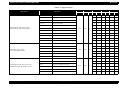
Stylus Photo R2880
Table 1-6. Print Mode (Color)
Table 1-6. Print Mode (Color)
Media
• Plain paper
• Premium Bright White
Paper (EAI)
• Bright White Inkjet
Paper (others)
• Ultra Premium Glossy
Photo Paper
• EPSON Glossy Photo
Paper
• Premium Semigloss
Photo Paper
• Ultra Premium Photo
Paper Luster
• Glossy Photo Paper
Photo Paper Glossy
(EAI)
• Matte Paper
Heavyweight
• Double-sided Matte
Paper
• Photo Quality Inkjet
Paper
• Watercolor Paper Radiant White
• Velvet Fine Art Paper
• Ultra Smooth Fine Art
Paper
• Enhanced Matte Paper
• Archival matte paper
(EAI)
• Matte Paper
Heavyweight
• Double-sided Matte
Paper
Product Description
Print Mode
Resolution
(H x V) dpi
Draft/Economy
360x360
Fine
720x720
Super Photo
5760x1440
Fine
720x720
Photo
1440x720
Super Photo
5760x1440
Photo
1440x720
Super Photo
5760x1440
Photo
1440x720
Photo
1440x720
Super Photo
5760x1440
Dot Size
(cps*)
Economy
(240cps)
VSD2
(220cps)
VSD2
(220cps)
VSD2
(220cps)
VSD2
(220cps)
VSD2
(220cps)
VSD2
(220cps)
VSD2
(220cps)
VSD2
(220cps)
VSD2
(220cps)
VSD2
(220cps)
Bi-d
Micro
Weave
ON
OFF
ON
ON
ON
ON
ON
ON
Media
Print Mode
Resolution
(H x V) dpi
• PremierArt Matte
Scrapbook Photo Paper
(EAI only)
Photo
1440x720
Super Photo
5760x1440
Super Photo
1440x1440
Super Photo
1440x1440
• CD/DVD
• CD/DVD Premium
Surface
Dot Size
(cps*)
VSD2
(220cps)
VSD2
(220cps)
VSD3
(220cps)
VSD3
(220cps)
Bi-d
Micro
Weave
ON
ON
ON
ON
ON
ON
ON
ON
Note : The default is indicated by boldface.
Note * : cps = character per second
ON
ON
ON
ON
ON
ON
ON
ON
ON
ON
ON
ON
ON
ON
Printing Specifications
14
Confidential
EPSON Stylus Photo R1900/R2880/R2000
Revision E
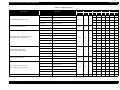
Table 1-7. Print Mode (Monochrome)
Table 1-7. Print Mode (Monochrome)
Media
• Plain paper
• Premium Bright White
Paper (EAI)
• Bright White Inkjet
Paper (others)
• Ultra Premium Glossy
Photo Paper
• EPSON Glossy Photo
Paper
• Premium Semigloss
Photo Paper
• Ultra Premium Photo
Paper Luster
• Glossy Photo Paper
Photo Paper Glossy
(EAI)
• Matte Paper
Heavyweight
• Double-sided Matte
Paper
• Photo Quality Inkjet
Paper
• Watercolor Paper Radiant White
• Velvet Fine Art Paper
• Ultra Smooth Fine Art
Paper
• Enhanced Matte Paper
• Archival matte paper
(EAI)
• Matte Paper
Heavyweight
• Double-sided Matte
Paper
Product Description
Print Mode
Resolution
(H x V) dpi
Draft/Economy
360x360
Fine
720x720
Super Photo
5760x1440
Fine
720x720
Photo
1440x720
Super Photo
5760x1440
Photo
1440x720
Super Photo
5760x1440
Photo
1440x720
Photo
1440x720
Super Photo
5760x1440
Dot Size
(cps*)
Economy
(240cps)
VSD2
(220cps)
VSD2
(220cps)
VSD2
(220cps)
VSD2
(220cps)
VSD2
(220cps)
VSD2
(220cps)
VSD2
(220cps)
VSD2
(220cps)
VSD2
(220cps)
VSD2
(220cps)
Bi-d
Micro
Weave
Media
Print Mode
Resolution
(H x V) dpi
ON
OFF
• PremierArt Matte
Scrapbook Photo Paper
(EAI only)
Photo
1440x720
ON
ON
Super Photo
5760x1440
Super Photo
1440x1440
Super Photo
1440x1440
• CD/DVD
ON
ON
ON
ON
ON
ON
ON
ON
ON
ON
ON
ON
ON
ON
ON
ON
ON
ON
• CD/DVD Premium
Surface
Dot Size
(cps*)
VSD2
(220cps)
VSD2
(220cps)
VSD3
(220cps)
VSD3
(220cps)
Bi-d
Micro
Weave
ON
ON
ON
ON
ON
ON
ON
ON
Note : The default is indicated by boldface.
Note * : cps = character per second
Printing Specifications
15
Confidential
EPSON Stylus Photo R1900/R2880/R2000
Revision E
1.2.4 Supported Paper
The table below lists the paper type and sizes supported by the printer. The Supported paper type and sizes vary depending on destinations (between EAI, EUR, and Asia).
Table 1-8. Supported Paper
Paper Name
Paper Size
Thickness
mm
Weight
g/m2
lb.
EAI
EUR
Asia
P*1
B*2
P*1
B*2
P*1
B*2
A3
297 x 420 mm
Y
-
Y
-
Y
-
US B
279.4 x 431.8 mm (11” x 17”)
Y
-
-
-
-
-
B4
257 x 364 mm
Y
-
Y
-
Y
-
Legal
215.9 x 355.6 mm (8.5”x14”)
Y
-
Y
-
Y
-
Letter
215.9 x 279.4 mm (8.5”x11”)
Y
-
Y
-
Y
-
A4
210 x 297 mm (8.3”x11.7”)
Y
-
Y
-
Y
-
B5
182 x 257 mm (7.2”x10.1”)
-
-
Y
-
Y
-
A5
148 x 210 mm (5.8”x8.3”)
-
-
Y
-
Y
-
Half Letter
139.7 x 215.9 mm (5.5”x8.5”)
Y
-
-
-
-
-
A6
105 x 148 mm (4.1”x5.8”)
Y
-
Y
-
Y
-
User Defined
89 x 127- 329 x 1117.6 mm
(3.56”x 5.08” - 13.16”x44.7”)
Y
-
Y
-
Y
-
Premium Inkjet Plain Paper
A4
210 x 297 mm (8.3”x11.7”)
0.11
80
21
-
-
Y
-
Y
-
Premium Bright White Paper
Letter
215.9 x 279.4 mm (8.5”x11”)
0.11
90
24
Y
-
-
-
-
-
Bright White Inkjet Paper
A4
210 x 297 mm (8.3”x11.7”)
0.13
92.5
25
-
-
Y
-
Y
-
Plain paper
Product Description
Printing Specifications
0.08-0.11
64-90 17-24
16
Confidential
EPSON Stylus Photo R1900/R2880/R2000
Revision E
Table 1-8. Supported Paper
Paper Name
Premium Photo Paper Glossy (EAI)
Premium Glossy Photo Paper (others)
Photo Paper Glossy (EAI)
Glossy Photo Paper (others)
Premium Photo Paper Semi-gloss (EAI)
Premium Semigloss Photo Paper (others)
Product Description
Paper Size
Thickness
mm
Weight
g/m2
lb.
EAI
EUR
Asia
P*1
B*2
P*1
B*2
P*1
B*2
A3+/SuperA3
329 x 483 mm
Y
Y
Y
Y
Y
Y
US B
279.4 x 431.8 mm (11” x 17”)
Y
Y
-
-
-
-
A3
297 x 420 mm
Y
Y
Y
Y
Y
Y
11” x 14”
279.4 x 355.6 mm
Y
Y
-
-
-
-
Letter
215.9 x 279.4 mm (8.5”x11”)
Y
Y
-
-
-
-
A4
210 x 297 mm (8.3”x11.7”)
Y
Y
Y
Y
Y
Y
8” x 10”
203.2 x 254 mm
Y
Y
-
-
-
-
5” x 7”
127 x 178 mm
Y
Y
Y
Y
Y
Y
4” x 6”
101.6 x 152.4 mm
Y
Y
Y
Y
Y
Y
16:9 wide
102 x 181 mm (4”x7.11”)
-
-
Y
Y
-
-
Roll paper
329 x 1,000 mm
Y
Y
Y
Y
Y
Y
A3+/SuperA3
329 x 483 mm
Y
Y
-
-
-
-
US B
279.4 x 431.8 mm (11” x 17”)
Y
Y
-
-
-
-
Letter
215.9 x 279.4 mm (8.5”x11”)
Y
Y
-
-
-
-
Y
Y
Y
Y
Y
Y
Y*3
Y*3
Y
Y
Y*3
Y*3
0.27
0.25
255
258
68
68
A4
210 x 297 mm (8.3”x11.7”)
5” x 7”
127 x 178 mm
4” x 6”
101.6 x 152.4 mm
Y
Y
Y
Y
Y
Y
A3+/SuperA3
329 x 483 mm
Y
Y
Y
Y
Y
Y
A3
297 x 420 mm
Y
Y
Y
Y
Y
Y
Letter
215.9 x 279.4 mm (8.5”x11”)
Y
Y
-
-
-
-
0.27
250
66
A4
210 x 297 mm (8.3”x11.7”)
-
-
Y
Y
Y
Y
4” x 6”
101.6 x 152.4 mm
Y
Y
Y
Y
Y
Y
Roll paper
329 x 1,000 mm
-
-
Y
Y
Y
Y
Printing Specifications
17
Confidential
EPSON Stylus Photo R1900/R2880/R2000
Revision E
Table 1-8. Supported Paper
Paper Name
Paper Size
A3+/SuperA3
329 x 483 mm
A3
297 x 420 mm
Ultra Premium Photo Paper Luster
Watercolor Paper - Radiant White
Product Description
g/m2
250
lb.
EAI
EUR
Asia
P*1
B*2
P*1
B*2
P*1
B*2
Y
Y
-
-
-
-
Y
Y
-
-
-
-
66
215.9 x 279.4 mm (8.5”x11”)
Y
Y
-
-
-
-
Roll paper
329 x 1,000 mm
Y
Y
-
-
-
-
329 x 1,000 mm
Y*4
Y*4
-
-
-
-
Y*4
Y*4
-
-
-
-
0.27
250
66
Roll paper
210 x 10,000 mm
A3+/SuperA3
329 x 483 mm
Y
Y
Y
Y
Y
Y
A3
297 x 420 mm
Y
Y
Y
Y
Y
Y
11” x 14”
279.4 x 355.6 mm
Y
Y
-
-
-
-
0.23
167
44
Letter
215.9 x 279.4 mm (8.5”x11”)
Y
Y
-
-
-
-
A4
210 x 297 mm (8.3”x11.7”)
-
-
Y
Y
Y
Y
8” x 10”
203.2 x 254 mm
Y
Y
-
-
-
-
A3+/SuperA3
329 x 483 mm
Y
Y
Y
Y
Y
Y
A3
297 x 420 mm
Y
Y
Y
Y
Y
Y
0.26
192
Letter
215.9 x 279.4 mm (8.5”x11”)
Y
Y
-
-
-
-
A4
210 x 297 mm (8.3”x11.7”)
-
-
Y
Y
Y
Y
Letter
215.9 x 279.4 mm (8.5”x11”)
Y
-
-
-
-
-
Double-sided Matte Paper
Presentation Paper Matte (EAI)
Photo Quality Inkjet Paper (others)
Weight
Letter
Roll paper
Archival Matte Paper (EAI)
Enhanced Matte Paper (others)
mm
0.27
Premium Luster Photo Paper
Premium Presentation Paper Matte (EAI)
Matte Paper Heavy-weight (others)
Thickness
0.22
185
49
A4
210 x 297 mm (8.3”x11.7”)
-
-
Y
-
Y
-
A3+/SuperA3
329 x 483 mm
Y
-
Y
-
Y
-
A3
297 x 420 mm
Y
-
Y
-
Y
-
US B
279.4 x 431.8 mm (11” x 17”)
Y
-
-
-
-
-
Letter
215.9 x 279.4 mm (8.5”x11”)
Y
-
-
-
-
-
A4
210 x 297 mm (8.3”x11.7”)
Y
-
Y
-
Y
-
A3+/SuperA3
329 x 483 mm
Y
Y
Y
Y
Y
Y
Printing Specifications
0.12
0.29
102
190
27
51
18
Confidential
EPSON Stylus Photo R1900/R2880/R2000
Revision E
Table 1-8. Supported Paper
Paper Name
Paper Size
A3+/SuperA3
Thickness
Weight
mm
g/m2
lb.
0.48
260
69
329 x 483 mm
Velvet Fine Art Paper
EAI
EUR
Asia
P*1
B*2
P*1
B*2
P*1
B*2
Y
Y
Y
Y
-
-
Y
Y
-
-
-
-
Letter
215.9 x 279.4 mm (8.5”x11”)
Ultra Smooth Fine Art Paper
A3+/SuperA3
329 x 483 mm
0.46
325
86
Y
Y
-
-
-
-
PremierArt Matte Scrapbook Photo Paper
12” x12”
305 x 305 mm
0.30
205
52
Y*5
Y*5
-
-
-
-
Photo Quality Self Adhesive Sheet
A4
210 x 297 mm (8.3”x11.7”)
0.19
167
44
Y
-
Y
-
Y
-
CD/DVD
CD/DVD Premium Surface
ø 12cm
ø 12cm
-
-
Y
-
Y
-
Y
-
ø 8cm
ø 8cm
-
-
Y
-
Y
-
Y
-
Enhanced Matte Posterboard*6
A3+
329 x 483 mm
-
-
Y*5
-
-
-
Note *1:
“Y” in the “P” column stands for “the paper type/size is Supported”.
*2:
“Y” in the “B” column stands for “Borderless printing is available”.
*3:
Stylus Photo R2880 only.
*4:
Not supported by Stylus Photo R2880.
*5:
Guaranteed under certain conditions.
*6:
Only front manual feed is available.
C A U T IO N
1.2
Make sure the paper is not wrinkled, fluffed, torn, or folded.
The curve of paper must be 5 mm or below.
When printing on an envelope, be sure the flap is folded neatly.
Do not use the adhesive envelopes.
Do not use double envelopes and cellophane window envelopes.
Product Description
Printing Specifications
19
Confidential
EPSON Stylus Photo R1900/R2880/R2000
Revision E
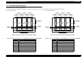
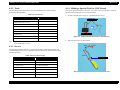
1.2.5 Printing Area
LM
Stylus Photo R1900
Table 1-9. Printing Area (Margins)
Print Mode
Paper Size
Right (RM)
Top (TM)
Bottom (BM)
3 mm
3 mm
3 mm
3 mm
3 mm*
3 mm*
30 mm*
21 mm*
A3/A3+/SuperA3
3.5 mm*
3.5 mm*
3 mm*
4.52 mm*
A4/Letter to 5” x 7”
2.5 mm*
2.5 mm*
3 mm*
4.02 mm*
4” x 6”
2.54 mm*
2.54 mm*
1.34 mm*
2.54 mm*
0 mm
0 mm
30 mm
21 mm
Roll paper
Borderless
print
Roll paper
Stylus Photo R2880
Paper Size
Borderless
print
Right (RM)
Top (TM)
Bottom (BM)
3 mm
3 mm
3 mm
3 mm
Roll paper
3 mm
3 mm
40 mm
21 mm
Board paper
3 mm
3 mm
20 mm
20 mm
A3/A3+/SuperA3
3.5 mm*
3.5 mm*
3 mm*
4.52 mm*
A4/Letter to 5” x 7”
2.5 mm*
2.5 mm*
1.34 mm*
2.54 mm*
2.54 mm*
2.54 mm*
1.34 mm*
2.54 mm*
40 mm
21 mm
4” x 6”
Roll paper
Note * :
RM
TM
TM
Print Area
Print Area
BM
Paper Size
BM
Figure 1-2. Printing Area
Margin
Left (LM)
Standard print Any size
LM
Paper Feed Direction
Table 1-10. Printing Area (Margins)
Print Mode
RM
Margin
Left (LM)
Standard print Any size
Cut Sheet (Borderless)
Cut Sheet (Standard)
The printing area for this printer is shown below.
0 mm
0 mm
The margins for Borderless print are margins that bleed off the edges of paper.
Product Description
Printing Specifications
20
Confidential
EPSON Stylus Photo R1900/R2880/R2000
Revision E
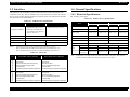
1.3 Interface
1.4 General Specifications
This printer has two USB device ports on the rear side to connect the printer with
computers or the like, and one USB host port on the front side to connect an external
device such as a DSC (digital still camera) with the printer. The table below describes
the specifications of each USB port.
1.4.1 Electrical Specifications
Primary power input
Table 1-13. Primary Power Specifications
Table 1-11. USB Interface Specifications
Item
Compatible standards
USB Device port
Item
USB Host port*
• Universal Serial Bus
Specifications Revision 2.0
• Universal Serial Bus Device
Class Definition for Printing
Devices Version 1.1
• Universal Serial Bus
Specifications Revision 2.0
Data format
NRZI
Rated frequency
Input frequency range
Compatible connector
USB Series B
USB Series A
Insulation resistance
Max. cable length
2 [m] or less
1.8 [m] or less
Energy conservation
Printing
Note * : External devices that can be connected to the USB device port are:
DSC compliant with the USB Direct Print Protocol specification Rev 1.0
DSC compliant with the CIPA DC-001-2003 (PictBridge) specifications
Table 1-12. Device ID
Stylus Photo R2880 Stylus Photo R1900
Product
100-120V
220-240V
0.3 A
(max. 0.5 A)
0.5 A
(max. 1.0 A)
0.3 A
(max. 0.5 A)
50 to 60 Hz
50 to 60 Hz
49.5 to 60.5 Hz
49.5 to 60.5 Hz
AC1000Vrms (for one minute)
AC1000Vrms (for one minute)
International Energy Star Program compliant
Approx. 20 W
Approx. 20 W
Approx. 20 W
Approx. 21 W
Power
Sleep mode
Approx. 3.1 W Approx. 4.0 W
consumption
Standby mode
Approx. 0.2 W Approx. 0.5 W
(power-off)
Approx. 4.0 W
Approx. 4.0 W
Approx. 0.2 W
Approx. 0.4 W
Note : If the printer is not operated for more than three minutes, the printer shifts into the
standby mode and reduces the current to the motors to save power.
When IEEE 1284.4 is Enabled
When IEEE 1284.4 is Disabled
@EJL<SP>ID<CR><LF>
MFG:EPSON;
CMD:ESCPL2,BDC,D4,D4PX,ESCPR1;
MDL:Stylus[SP]Photo[SP]R1900;
CLS:PRINTER;
DES:EPSON[SP]Stylus[SP]Photo [SP]R1900;
@EJL<SP>ID<CR><LF>
MFG:EPSON;
CMD:ESCPL2,BDC;
MDL:Stylus[SP]Photo[SP]R1900;
CLS:PRINTER;
DES:EPSON[SP]Stylus[SP]Photo [SP]R1900;
@EJL<SP>ID<CR><LF>
MFG:EPSON;
CMD:ESCPL2,BDC,D4,D4PX,ESCPR1;
MDL:Stylus[SP]Photo[SP]R2880;
CLS:PRINTER;
DES:EPSON[SP]Stylus[SP]Photo [SP]R2880;
@EJL<SP>ID<CR><LF>
MFG:EPSON;
CMD:ESCPL2,BDC;
MDL:Stylus[SP]Photo[SP]R2880;
CLS:PRINTER;
DES:EPSON[SP]Stylus[SP]Photo [SP]R2880;
Product Description
220-240V
90 to 132 VAC 198 to 264 VAC 90 to 132 VAC 198 to 264 VAC
0.6 A
(max. 1.0 A)
Rated current
480 Mbps (High Speed)
100-120V
Stylus Photo R2880
Rated power supply voltage 100 to 120 VAC 220 to 240 VAC 100 to 120 VAC 220 to 240 VAC
Input voltage range
Transfer rate
Stylus Photo R1900
Interface
21
Confidential
EPSON Stylus Photo R1900/R2880/R2000
Revision E
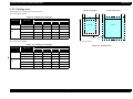
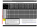
1.4.2 Environmental Conditions
1.4.3 Durability
Table 1-14. Environmental Conditions
Condition
Temperature*1
Humidity*1,2
Operating
10 to 35°C
(50 to 95°F)
20 to 80%
Storage*3
(unpacked)
-20 to 40°C*4
(-4°F to 104°F)
5 to 85%
Note *1:
Shock
Vibration
1G
0.15G,
10 to 55Hz
(1 msec or less)
2G
(2 msec or less)
0.50G,
10 to 55Hz
Total print life:
Black 16,000 pages (A4, 3.5% duty),
Color 10,000 pages (A4, 5% duty),
or five years which ever comes first
Printhead:
Six billions shots (per nozzle) or five years which ever comes
first
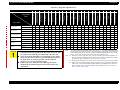
1.4.4 Acoustic Noise
The combined Temperature and Humidity conditions must be within the blue-shaded
range in Figure 1-3.
*2:
*3:
*4:
No condensation
Non-operating with unpacked.
Must be less than 1 month under 40°C.
1.4.5 Safety Approvals (Safety standards/EMI)
USA
90
Humidity (%)
T.B.D. dB (when printing from PC, on Premium Glossy Photo Paper, in highest
quality)
Argentina
Australia
UL60950-1
FCC Part15 Subpart B Class B
CAN/CSA-C22.2 No.60950-1
CAN/CSA-CEI/IEC CISPR 22 Class B
NOM-019-SCFI-1998
CNS13438 Class B
CNS14336
EN60950-1
EN55022 Class B
EN61000-3-2, EN61000-3-3
EN55024
EN60950-1
GOST-R (IEC60950-1, CISPR 22)
IEC60950-1
K60950-1
KN22 Class B
KN61000-4-2/-3/-4/-5/-6/-11
GB4943
GB9254 Class B, GB17625.1
IEC60950-1
AS/NZS CISPR22 Class B
Hong Kong
IEC60950-1
80
Canada
70
60
Mexico
Taiwan
50
EU
40
30
Germany
Russia
Singapore
Korea
20
27/80
10/50
20/68
30/86 35/95 40/104
Temperature (°C/°F)
China
Figure 1-3. Temperature/Humidity Range
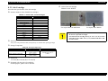
C A U T IO N
When returning the repaired printer to the customer, make sure
the Printhead is covered with the cap and the ink cartridge is
installed.
If the Printhead is not covered with the cap when the printer is off,
turn on the printer with the ink cartridge installed, make sure the
Printhead is covered with the cap, and then turn the printer off.
Product Description
General Specifications
22
Confidential
EPSON Stylus Photo R1900/R2880/R2000
Revision E
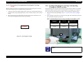
1.5 Operation Buttons & Indicators (LEDs)
Power LED
Paper LED
Ink LED
1.5.1 Operation Buttons
The printer has the following four operation buttons.
Table 1-15. Operation Buttons
Button
Function
Power
Turns the power ON/OFF.
Paper
Feeds or ejects paper.
Ink
Runs a sequence of ink cartridge replacement or cleaning.
Roll Paper
Prints the cutting line on the roll paper or feeds the paper
backwards out of the printer.
Power Button
Ink Button
Paper Button
Roll Paper Button
Figure 1-4. Buttons & LEDs
1.5.2 Indicators (LEDs)
Eleven indicators (LEDs) are provided to indicate settings or printer status.
Table 1-16. Indicators (LEDs)
LED
Function
Power LED (green)
Lights at power-on.
Flashes during some sequence is in progress.
Flashes at high speed during power-OFF sequence.
Ink LED (orange)*1
Lights or flashes when an ink-related error occurs.*2
Paper LED (orange)*1
Lights or flashes when an paper- or CDR-related error occurs.*2
Cartridge LED (red) x 8
Indicates an ink-related error of each ink cartridge.*2
Note *1:
*2:
The Ink LED and Paper LED stay OFF when printing from PC.
See Table 1-18 "Indicators (LEDs) Function" for the LED status at error occurrence.
Product Description
Operation Buttons & Indicators (LEDs)
23
Confidential
EPSON Stylus Photo R1900/R2880/R2000
Revision E
1.5.3 Operation Buttons & LEDs Functions
Table 1-17. Operation Button Functions
Detailed information on the buttons and LEDs functions are listed below.
Table 1-17. Operation Button Functions
Printer
Status
Button
Power
Ink
Off
• Turns the power on.
On
• Turns the power off.
On
• Runs a sequence of ink cartridge replacement. The
carriage moves to set the ink cartridge to the position
for replacement.
• When an ink cartridge has been set in the ink replacement
position, moves the carriage to the home position.
On
• Feeds or ejects paper.*1
• Recovers from a multi-feed error and feeds paper to
restart the print job.
• Feeds paper when paper is loaded after a no-paper
error occurs.
• Ejects a jammed paper when a paper jam error occurs.
• Cancels the print job during printing.
• Runs a sequence of ink cartridge replacement when
an ink-out, or ink color error*2 occurs. The carriage
moves to set the ink cartridge to the position for
replacement.
• When an ink cartridge has been set in the ink replacement
position, moves the carriage to the home position.
During CDR
printing
• Recovers from a paper jam error.
• Cancels the print job during printing.
On
• Runs a head cleaning.
• Runs a sequence of ink cartridge replacement when
ink level low, ink out, no ink cartridge, or ink color
error*2 has occurred.
On
• Feeds the roll paper to the cutting position and prints
a cutting line.
• Returns the cutting position.
• When an ink cartridge has been set in the ink
replacement position, moves the carriage to the home
position.
Paper
Ink
(when held for three
seconds or longer)
Roll Paper
Function
Product Description
Button
Printer
Status
Function
Roll Paper
(when held for three
seconds or longer)
On
• Ejects the paper backwards out of the printer.
• When an ink cartridge has been set in the ink
replacement position, moves the carriage to the home
position.
Power + Ink *2
(combination)
At power on
• Turns the power on in rub reduction mode when
connected to DSC (digital still camera).
Power + Ink *2
(combination)
(Hold down the Ink
button for 7 sec or
longer)
On
Power + Paper *1
(combination)
At power on
• Forcefully turns the power off.
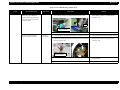
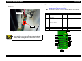
• Prints a nozzle check pattern*2 when not connected to
the PC.*3
Note 1: The paper cannot be fed or ejected if the CDR Tray Base is open.
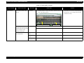
2: Stylus Photo R2880 only.
3: The nozzle check pattern printed by the printer is shown in Figure 1-5 and Figure 1-6.
Operation Buttons & Indicators (LEDs)
24
Confidential
EPSON Stylus Photo R1900/R2880/R2000
Yellow
Magenta
1
Matte Black
Orange
2
1
2
Red
Revision E
1
Cyan
Photo Black
1
1
2
Light Light
Black
Light
Magenta
360
359
360
359
360
Light
Black
180
Black
1
1
1
180
359
Light
Cyan
180
1
180
Magenta
Cyan
1
1
180
180
Yellow
1
180
180
359
720 dpi VSD2
720 dpi VSD1
0.141 mm (1/180 inch)
0.141 mm (1/180 inch)
32 dots
32 dots
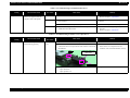
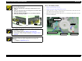
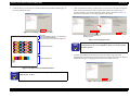
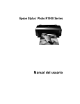
Note : The numbers shown in the figure are nozzle numbers. The numbers and color names
are not printed on an actual nozzle check pattern.
Figure 1-5. Nozzle Check Pattern (Stylus Photo R1900)
Product Description
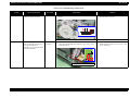
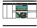
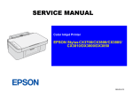
Note : The numbers shown in the figure are nozzle numbers. The numbers and color names
are not printed on an actual nozzle check pattern.
Figure 1-6. Nozzle Check Pattern (Stylus Photo R2880)
Operation Buttons & Indicators (LEDs)
25
Confidential
EPSON Stylus Photo R1900/R2880/R2000
Revision E
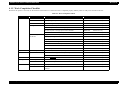
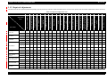
Table 1-18. Indicators (LEDs) Function
Indicators (LEDs)
Power
Paper
Ink
Priority*1
Power OFF
Flashes at
high speed
OFF
OFF
1
Fatal error
OFF
Flashes at
high speed
Flashes at
high speed
2
Maintenance request
OFF
Flashes
alternately 1
Flashes
alternately 2
3
CDR guide error
--
Flashes 2
Flashes at
high speed
4
Paper path error
--
Flashes
--
Paper (CDR) jam
--
Flashes
--
Cover open error
--
Flashes
--
Multi-feed error
--
ON
--
No paper error
--
ON
--
Printer Status
Flashes
--
--
7
--
--
8
CSIC error
--
--
ON*2
No ink cartridge error or ink-out error
--
--
ON*2
Ink Color error*4
--
--
Flashes at
high speed*2
Data processing/Printing from camera
Flashes
--
--
Connected to non-supported external
device
--
Flashes 2
Flashes 3
Connected to USB hub
--
Flashes 4
Flashes
Ink level low
--
--
Flashes*2
Connected to camera
(with rubbing reduction)
Flashes 4
--
--
Connected to camera
(without rubbing reduction)
Flashes 2
--
--
Flashes
--
--
ON
ON
ON
Note *1:
Stylus Photo R2880 only.
--:
Flash:
Flash 2:
No change
Repeats turning On and Off every 1.25 seconds.
Repeats On for 0.5 seconds, Off for 0.5 seconds,
On for 0.5 seconds, and Off for 1.0 second.
Flash 3:
Repeats Off for 0.5 seconds, On for 0.5 seconds,
Off for 0.5 seconds, and On for 1.0 second.
Flash 4:
Repeats On for 2.0 seconds and Off for 0.5 seconds.
Flash at high speed: Repeats turning On and Off every 0.5 seconds.
Flashes alternately 1: Same as the “Flash”
Flashes alternately 2: Repeats turning Off and On every 1.25 seconds.
6
Flashes
Reset
*4:
5
Ink sequence is in progress
request*3
The cartridge LED corresponding to each ink cartridge lights.
The all LEDs light for 0.2 seconds when a reset request is received.
Note :
Ink cartridge replacement is in progress
Power ON
*2:
*3:
9
10
11
12
13
--
When two or more errors occur at the same time, the one with higher priority will be indicated.
Product Description
Operation Buttons & Indicators (LEDs)
26
Confidential
EPSON Stylus Photo R1900/R2880/R2000
Revision E
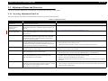
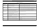
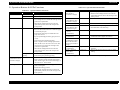
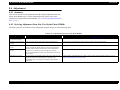
1.5.4 Errors & Remedies
Note :
Table 1-19. Errors & Remedies
Error
Error
Note *1:
Remedies
Fatal error
A mechanical error has occurred. Turn the power Off and back it On.
Maintenance
request
Waste ink pads need to be
replaced.
CDR guide error
Replace the waste ink pads and reset
the counter.
• The CDR Tray Base was open
when receiving or printing a
ASF print job.
Close the CDR Tray Base.
• The CDR Tray Base was
closed when receiving or
printing a CDR print job.
Open the CDR Tray Base.
A paper jam has occurred.
<When printing on paper>
Remove the jammed paper and press
the Paper button.*1
<When printing on CDR>
Remove the jammed CDR tray and
press the Paper button.
Failed to feed paper.
Load paper correctly and press the
Paper button.*1
Multi-feed
Multiple sheets of paper were fed
at the same time.
Press the Paper button to eject the
multiple sheets.*1
Ink-out
The cartridge has run out of ink.
Replace the cartridge with a new one.*2
No ink cartridge
Ink cartridge(s) was not detected. Replace the cartridge with a new one.*2
Wrong ink
cartridge
Incorrect ink cartridge(s) was
detected.
Replace the cartridge with the correct
one.*2
Paper path error
The paper was loaded in a
different way from the specified
one.
Eject the fed paper and press the Paper
button after loading paper in the
specified way.
Cover open error
Printing was executed with the
Printer Cover open.
Close the Printer Cover.
The black ink cartridge was
replaced during printing.
Replace the cartridge with the one
used before the error.
Cleaning after black ink
replacement cannot be
performed.
Replace the black ink cartridge with
the one used before the error, or the
one that has sufficient amount of ink.
Paper jam
No paper
Ink Color error*3
Product Description
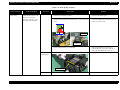
For more information on the remedies, see "3.1.1 Troubleshooting according to
Error Messages" (p.34).
When the CDR Tray Base is opened, close the CDR Tray Base and press the Paper
button.
*2:
When the CDR tray has been inserted, remove the CDR tray and press the Ink button.
*3:
Stylus Photo R2880 only.
Operation Buttons & Indicators (LEDs)
27
Confidential
CHAPTER
2
OPERATING PRINCIPLES
Confidential
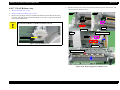
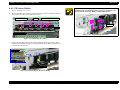
EPSON Stylus Photo R1900/R2880/R2000
Revision E
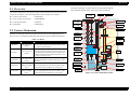
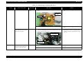
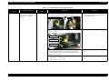
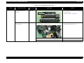
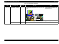
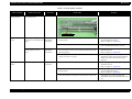
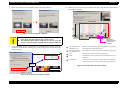
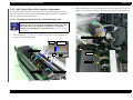
2.1 Overview
The basic mechanism is almost same as the Stylus Photo R1800.
The schematic diagram below shows the printer mechanism.
This chapter explains the operating principles of the mechanical sections and electrical
circuits in this product. The main components of this product are as follows.
Control circuit board
: C698 MAIN
Power supply circuit board
: C698 PSB/PSE
Control panel board
: C698 PNL
LED board
: C698 PNL-B
Front Paper
Eject Roller
APG Sensors
Rear Paper
Eject Roller
APG Motor
Type
Applications/Functions
DC motor with
brushes
Used for carriage driving. Makes little noise during
driving. The CR linear scale and CR encoder sensor
are used to control the motor.
PF Motor
DC motor with
brushes
Drives the Paper loading rollers at the time of fixedvalue paper loading or paper feed/eject operation. To
grasp the paper feed pitch, the precision gear surface
is fitted with the PF scale and the PF encoder sensor
is used to control the motor.
APG Motor
DC motor with
brushes
Drives the Carriage Unit at the time of PG setting.
The two APG Sensors are driven vertically to control
the motor.
ASF Motor
4-phase, 48-pole
PM type stepping
motor
Drives the paper feed operation of the ASF. Since
this is a stepping motor, any scales or photo sensors
to know the driving conditions are not required.
Pump Motor
4-phase, 48-pole
PM type stepping
motor
Drives the pump, wiper, etc. of the Ink System. Since
this is a stepping motor, any scales or photo sensors
to know the driving conditions are not required.
APF Sensor
Timing Belt
Cover Open
Sensor
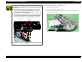
Table 2-1. Motors
Operating Principles
PF Motor
CR Scale
Like the conventional model, this product uses DC motors and stepping motors as
power sources. The following table describes the motor types and their applications.
CR Motor
PF Scale
PF Roller
2.2 Printer Mechanism
Motor Name
PF Encoder
Sensor
CR Encoder
Sensor
PW Sensor
LD Roller
Ink Mark
Sensor
Retard
Roller
Carriage
Unit
Ink System
Unit
PE Sensor
Pump Motor
ASF Motor
CD-R Sensor
Carriage
Shaft
CR Motor
Figure 2-1. Printer Mechanism Outline
Overview
29
Confidential
EPSON Stylus Photo R1900/R2880/R2000
Revision E
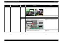
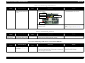
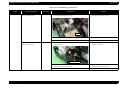
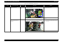
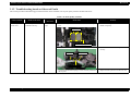
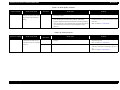
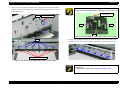
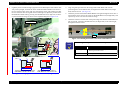
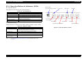
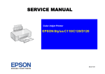
2.3 Printhead Specifications
The Printhead of this product is a F-Mach head.
The following shows the arrangement of the nozzles and the color arrangement of each nozzle line when viewed the Print Head from behind.
Stylus Photo R2880
Stylus Photo R1900
7.620mm
7.620mm
7.620mm
(216/720inch) (216/720inch) (216/720inch)
2.258mm
2.258mm
2.258mm
2.258mm
(64/720inch) (64/720inch) (64/720inch) (64/720inch)
7.620mm
7.620mm
7.620mm
(216/720inch) (216/720inch) (216/720inch)
2.258mm
2.258mm
2.258mm
2.258mm
(64/720inch) (64/720inch) (64/720inch) (64/720inch)
Paper feeding
direction
Line A
Line C
Line B
Line E
Line D
Line G
Line F
Paper feeding
direction
Line A
Line H
0.141mm
(1/180inch)
0.071mm
(1/360inch)
Line C
Line B
Line E
Line D
Line G
Line F
Line H
0.141mm
(1/180inch)
0.071mm
(1/360inch)
31.89mm
31.89mm
41.66mm
41.66mm
Carriage moving direction
Carriage moving direction
Figure 2-2. Nozzle Arrangement (Stylus Photo R1900)
Figure 2-3. Nozzle Arrangement (Stylus Photo R2880)
Table 2-2. Nozzle Lines and the Corresponding Ink Color (Stylus Photo R1900)
Table 2-3. Nozzle Lines and the Corresponding Ink Color (Stylus Photo R2880)
Line
Ink
Line
A
Yellow
A
Light Light Black
B
Magenta
B
Vivid Light Magenta
C
Matte Black
C
Light Cyan
D
Red
D
Light Black
E
Orange
E
Matte Black/Photo Black
F
Photo Black
F
Cyan
G
Gloss Optimizer
G
Vivid Magenta
H
Cyan
H
Yellow
Operating Principles
Printhead Specifications
Ink
30
Confidential
EPSON Stylus Photo R1900/R2880/R2000
Revision E
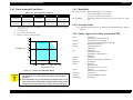
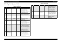
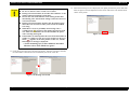
2.4 PG Setting
As this printer uses an Auto PG (APG), an appropriate PG position is set according to the used paper type.
The following table indicates the PG positions, the main applications of each position, and the relationships between the two sensors used with the APG.
Table 2-4.
Application
Printing
PG Position
PG (– –)
• Photo paper
(A4,Letter)
PG (–)
• Roll paper
• Photo Matte paper
Non-printing
PG (Typ)
• Plain paper
• Exclusive paper
• PG (-) rub avoidance
PG (+)
• Envelope
• PG (Typ) rub avoidance
PG (++)
• CD/DVD
Release
–
• Standby position after
• Ink Mark Sensor reading. • Initialization at power-on • Standby state for CD/
power-on (When the
(Detection of dot
DVD feeding
• Cleaning (wiping)
CDR Tray Base is
missing)
• Paper jam removal
• Ink Cartridge
closed.)
replacement
• At power-off
• Ink Mark Sensor reading.
(Auto Bi-D)
–
–
PG value
1.05mm
1.20mm
1.70mm
2.10mm
4.50mm
–
Sensor
PG (– –)
PG (–)
PG (Typ)
PG (+)
PG (++)
Release
APG Sensor 1*
Low
Low
Low
Low
Low
Low
APG Sensor 2
Low
Low
Low
Low
High
High
Note "*": The signal output is “High” while the PG positions are changed.
Operating Principles
PG Setting
31
Confidential
EPSON Stylus Photo R1900/R2880/R2000
Revision E
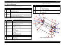
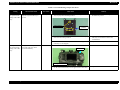
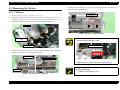
2.5 Motors & Sensors
Table 2-6. List of Sensors
Fig.
Motors
8
Name
Specific
Ink Mark Sensor
Type: Diffuse reflective photo interrupter
Drive voltage: 3.3(5)VDC±5%
Drive voltage: 3.3VDC±5%
9
CDR Sensor
Type: Mechanical contact
Sensor output:
• High: CDR Tray Base open
• Low: CDR Tray Base closed
10
Type: Mechanical contact
Sensor output:
• High: Cover closed
• Low: Cover open
Drive voltage: 3.3VDC±5%
Cover Open
Sensor
Table 2-5. List of Motors
Fig.
Name
Specific
PF Motor
Type: DC Motor
Armature resistance: 21.2 ±10%
Drive voltage: 42VDC±5%
B
APG Motor
Type: DC Motor
Armature resistance: 64.7 ±15%
Drive voltage: 42VDC±5%
C
ASF Motor
Type: 4-phase 48-pole PM type stepping motor
Winding resistance: 7.0 ±10% (per phase at 25°C)
Drive voltage: 42VDC±5%
D
CR Motor
Type: DC Motor
Armature resistance: 23.6 ±10%
Drive voltage: 42VDC±5%
E
Pump Motor
Type: 4-phase 48-pole PM type stepping motor
Drive voltage: 42VDC±5%
Winding resistance: 10.3 ±10% (per phase at 25°C)
A
Sensors
1
Name
Type: Rotary Encoder
APG Sensor (1)
Type: Transmissive photo interrupter
Drive voltage: 3.3VDC±5%
Sensor output:
• High: In the domain of each PG position
• Low: Between PG positions
Drive voltage: 3.3VDC±5%
APG Sensor (2)
Type: Transmissive photo interrupter
Sensor output:
• High: In the domain of large PG
• Low: In the domain of small PG
Drive voltage: 3.3VDC±5%
ASF Sensor
Type: Transmissive photo interrupter
Sensor output:
• High: Home position
• Low: Other than home position
Drive voltage: 3.3VDC±5%
5
PE Sensor
Type: Transmissive photo interrupter
Sensor output:
• High (2.4V or more): No paper
• Low (0.4V or less): Paper exists
6
CR Encoder sensor
Type: Linear Encoder
Drive voltage: 3.3VDC±5%
Drive voltage: 3.3VDC±5%
PW Sensor
Type: Reflective photo interrupter
Sensor output:
• High: No paper
• Low: Paper exists
3
4
7
Operating Principles
3
5
A
Specific
PF Encoder sensor
2
4
2
Table 2-6. List of Sensors
Fig.
B
6
Drive voltage: 3.3VDC±5%
1
C
D
10
E
9
8
7
Figure 2-4. Motors and Sensors Layout
Motors & Sensors
32
Confidential
CHAPTER
3
TROUBLESHOOTING
Confidential
EPSON Stylus Photo R1900/R2880/R2000
Revision E
3.1 Overview
This chapter describes unit-level troubleshooting.
3.1.1 Troubleshooting according to Error Messages
After checking the printer LED and STM3 error indications, you can grasp the fault location using the check list in this section. When you find the fault location, refer to Chapter 4
“Disassembly and Reassembly” and change the corresponding part and/or unit. The following table indicates the check point reference tables corresponding to the error states (LED
and STM3).
Table 3-1. List of Error Messages
Error Status
Communication error
LED Indications
Power
-
Paper
-
STM3 Message
Ink
-
Communication error
Check all connections and make sure all devices are on. If the power was
turned off during printing, cancel the print job. If the error does not clear,
see your printer documentation.
Model Difference
-
-
-
Different device from specified
Attempting to connect to a different device from that specified in the driver.
Check the driver settings and the device.
Printer cover open
error
-
Flash
-
Printer cover open
Close the printer cover.
CDR Guide error
-
Flash 2
Paper out error
Paper (CDR) jam
Troubleshooting
-
-
Light
Flash
See the table for Troubleshooting
Refer to Table 3-2 "Troubleshooting of Communication
Error" (P.37)
Refer to Table 3-3 "Troubleshooting of Printer Cover
Open Error" (P.39)
Flashes at Front paper feed guide open
high speed Remove the CD/DVD tray, then close the front paper feed guide.
Refer to Table 3-4 "Troubleshooting of CDR Guide
Error" (P.40)
-
Media out or not loaded correctly
For sheets of paper, reload the paper correctly, then press the Paper button
on the printer.
For roll paper or velvet paper, insert the end of the paper into the printer.
For a CD or DVD, load the CD/DVD tray correctly, then press the Paper
button on the printer.
-
Paper jam or CD/DVD tray jam
For sheets of paper, turn off the printer and then remove any jammed paper Refer to Table 3-6 "Troubleshooting of Paper Jam
by hand.
Error" (P.45)
For a CD or DVD, remove the CD/DVD tray. Next, press the Paper button
on the printer or click the Eject button if it appears on this screen.
Overview
Refer to Table 3-5 "Troubleshooting of Paper Out
Error" (P.41)
34
Confidential
EPSON Stylus Photo R1900/R2880/R2000
Revision E
Table 3-1. List of Error Messages
Error Status
Paper Mismatch Error
Multi-feed error
Ink low
Ink Color error*1
Troubleshooting
LED Indications
Power
-
-
-
-
Paper
Flash
Light
-
-
Ink
STM3 Message
See the table for Troubleshooting
-
Paper Source setting not selected correctly
For sheets of paper, remove the roll paper or velvet paper and print again.
Refer to Table 3-7 "Troubleshooting of Paper Mismatch
For roll paper, select Roll Paper as the Paper Source setting in the printer
Error" (P.46)
driver and print again.
For velvet paper, select Velvet Fine Art Paper as the Paper Source setting in
the printer driver and print again.
-
Page not printed or multi-page error
A page has not been printed, multiple pages have been fed into the printer at Refer to Table 3-8 "Troubleshooting of Multi-feed
error" (P.48)
once, or the wrong paper size has been fed into the printer. Remove and
reload the paper. Press the Paper button if necessary.
Light*2
Ink low
Black: XXXX*2
Color: XXXX
...................
You may continue printing, or click the How to button to
change the ink cartridge now.
Refer to Table 3-9 "Troubleshooting of Ink Low" (P.48)
Ink cartridges cannot be replaced
There are two possible causes.
Because there is only a small amount of ink remaining,
you cannot replace it with a different type of black ink cartridge.
(However, you may be able to replace it with the same type of black ink
cartridge.)
Flashes at Replace it with a new ink cartridge. We recommend using genuine Epson Refer to Table 3-10 "Troubleshooting of Ink Color Error
(Stylus Photo R2880 only)" (P.48)
high speed*2 ink cartridges.
Or, the currently installed black ink differs to the type of cartridge used
when printing started.
Replace the currently installed black ink cartridge with the same type of
previously installed black ink cartridge.
Once it is replaced, printing will resume automatically. If you do not want to
replace the ink cartridge, click the Cancel button.
Overview
35
Confidential
EPSON Stylus Photo R1900/R2880/R2000
Revision E
Table 3-1. List of Error Messages
Error Status
Ink-out error
No ink cartridge/
CSIC error
LED Indications
Power
-
-
-
Maintenance request
Off
Fatal error
Off
Note *1:
Paper
-
STM3 Message
Ink
Light*2
Replace Cartridge
Black: XXXX*2
Color: XXXX
...................
Epson recommends the genuine Epson cartridges listed above. Click the
How to button for ink cartridge replacement instructions.
Light*2
Ink cartridges cannot be recognized
Black: XXXX*2
Color: XXXX
...................
Epson recommends the genuine Epson cartridges listed above. Click the
How to button for ink cartridge installation instructions.
Refer to Table 3-12 "Troubleshooting of No Ink
Cartridge/CSIC Error" (P.49)
Service required
Refer to Table 3-13 "Troubleshooting of Maintenance
Flashes
Flashes
alternately 1 alternately 2 Parts inside your printer are at the end of their service life. See your printer Request" (P.50)
documentation.
Flashes at
high speed
General error
Flashes at
high speed Delete all print jobs and turn the printer off. Remove any foreign objects
from inside the printer. After a few minutes, turn the printer back on.
Refer to Table 3-14 "Troubleshooting of Fatal Error"
(P.51)
Stylus Photo R2880 only.
*2:
The cartridge LED corresponding to each ink cartridge lights.
*3:
The “XXXX” represents the part number of the Ink Cartridge.
Refer to "1.2.2 Ink Cartridge" (p11).
Note :
See the table for Troubleshooting
--:
Flash:
Flash 2:
Flash at high speed:
Flashes alternately 1:
Flashes alternately 2:
Troubleshooting
No change
Repeats turning On and Off every 1.25 seconds.
Repeats On for 0.5 seconds, Off for 0.5 seconds,
On for 0.5 seconds, and Off for 1.0 second.
Repeats turning On and Off every 0.5 seconds.
Same as the “Flash”
Repeats turning Off and On every 1.25 seconds.
Overview
36
Confidential
EPSON Stylus Photo R1900/R2880/R2000
Revision E
Table 3-2. Troubleshooting of Communication Error
Occurrence
Timing
At power-on
Phenomenon Detail
Faulty Part/
Part Name
The printer does not operate at all. Panel FFC
Check Point
Remedy
1. Check that the Panel FFC is connected to the Panel Board
connector and Main Board connector.
Panel Board
connector
1. Connect the Panel FFC to the Panel Board and
Main Board connectors.
Panel FFC
CN4
Panel FFC
2. Check the Panel FFC for damages.
2. Replace the Panel FFC with a new one.
Panel Board
1. Check the Panel Board for damages.
1. Replace the Panel Board with a new one.
Power Supply
Board
1. Check that the connector cable of the Power Supply Board is
connected to the Main Board connector CN60.
1. Connect the connector cable of the Power
Supply Board to the Main Board connector
CN60.
Connector cable of the
Power Supply Board
Blue line
CN60
1Pin side
2. Check that the blue colored pin of the Power Supply Board
connector cable is inserted into the 1 Pin of the Main Board
connector CN60 as shown in the above picture.
Troubleshooting
Overview
2. Reconnect the Power Supply Board connector
cable so that the blue colored pin is inserted
into the 1 Pin.
37
Confidential
EPSON Stylus Photo R1900/R2880/R2000
Revision E
Table 3-2. Troubleshooting of Communication Error
Occurrence
Timing
At power-on
Phenomenon Detail
Faulty Part/
Part Name
The printer does not operate at all. Power Supply
Board
Check Point
Remedy
3. Check that the Fuse F1 on the Power Supply Board has not
blown.
3. Replace the Power Supply Board with a new
one.
Power Supply
Board
Fuse F1
4. Check the components on the Power Supply Board for damage. 4. Replace the Power Supply Board with a new
one.
After the power-on sequence has Main Board
started, the LED turns off and the
printer does not operate.
1. Check that the Relay connector of the ASF Motor and the Relay 1. Connect the Relay connector of the ASF Motor
and the Relay connector of the Pump Motor
connector of the Pump Motor are not connected to the wrong
connector causing a short circuit.
correctly, and replace the Main Board with a
new one.
Relay connector of
the ASF Motor
Relay connector of
the Pump Motor
At operation
Troubleshooting
Operation at power-on is normal, Interface cable
but the error appears when the
print job is sent to the printer.
1. Check that the Interface cable is connected between the PC and
printer.
1. Connect the Interface cable to the PC and
printer.
2. Check the Interface cable for breaking.
2. Replace the Interface cable with a new one.
Overview
38
Confidential
EPSON Stylus Photo R1900/R2880/R2000
Revision E
Table 3-2. Troubleshooting of Communication Error
Occurrence
Timing
At operation
Phenomenon Detail
Faulty Part/
Part Name
Operation at power-on is normal, USB
but the error appears when the
print job is sent to the printer.
Printer Driver
Main Board
Check Point
Remedy
1. Check that the PC and printer are connected via the USB hub.
1. Configure the USB ID setting.
Refer to Chapter 5 "Adjustment".
1. Check that the printer driver for Stylus Photo R1900 has already 1. Install the printer driver for Stylus Photo
been installed.
R1900.
2. Check that the connected printer is Stylus Photo R1900.
2. Connect the Stylus Photo R1900 printer.
1. Check that a wrong model name has not been input to the
EEPROM on the Main Board.
1. Make the initial setting using the Adjustment
Program.
Refer to Chapter 5"Adjustment".
Table 3-3. Troubleshooting of Printer Cover Open Error
Occurrence
Timing
During printing
Phenomenon Detail
A Printer Cover Open Error is
indicated during printing.
Faulty Part/
Part Name
Cover Open
Sensor
Check Point
Remedy
1. Check that the Printer Cover is not open.
1. Close the Printer Cover.
2. Check that the connector cable of the Cover Open Sensor is
connected to the Cover Open Sensor and connector CN4 on the
Panel Board.
2. Connect the connector cable of the Cover Open
Sensor to the Cover Open Sensor and
connector CN4 on the Panel Board correctly.
CN4
Connector of the Cover
Open Sensor
Panel Unit
3. Using a tester, check that the Cover Open Sensor is normal.
• Paper absent:0V
• Paper present:3.3V
Troubleshooting
Overview
4. Replace the Panel Unit with a new one.
39
Confidential
EPSON Stylus Photo R1900/R2880/R2000
Revision E
Table 3-4. Troubleshooting of CDR Guide Error
Occurrence
Timing
At operation
Phenomenon Detail
Faulty Part/
Part Name
CDR Guide Error is indicated on CDR Sensor
the LED and STM3 when CD/
DVD printing is executed after
the CDR Tray Base is opened and
the CDR Tray is inserted.
Check Point
Remedy
1. Check that the CDR Sensor is installed correctly.
OK
NG
2. Check that the connector cable of the CDR Sensor is connected
to the CDR Sensor and the connector on the Panel Board.
CDR Sensor
1. Install the CDR Sensor correctly.
2. Connect the connector cable of the CDR
Sensor to the CDR Sensor and the Panel Board.
Connector on the
Panel Board
Connector cable of
the CDR Sensor
Troubleshooting
3. Using a tester, check that the CDR Sensor is normal.
• CDR Tray Base open: 3.3V
• CDR Tray Base closed: 0V
3. Replace the CDR Sensor with a new one.
4. Check the CDR Sensor or connector cable for damages.
4. Replace the CDR Sensor with a new one.
Overview
40
Confidential
EPSON Stylus Photo R1900/R2880/R2000
Revision E
Table 3-5. Troubleshooting of Paper Out Error
Occurrence
Timing
At operation
Phenomenon Detail
Faulty Part/
Part Name
When the Paper Switch is
ASF Assy.
pressed, the LD Roller attempt to
feed paper but the paper is not
fed.
Check Point
Remedy
1. Check the LD Roller or Retard Roller of the ASF Assy for paper 1. Using a cleaning sheet, clean the LD Roller
dust and foreign matter.
and Retard Roller. The procedure is as follows.
(1) Place the cleaning sheet upside down and
put it into the ASF Assy.
(2) Press the Paper Switch to start paper feed.
(3) Repeat the above steps several times.
* To remove persistent contamination, staple
an alcohol-dampened cloth to a postcard
and clean the rollers in the following
method.
Cleaning sheet
Postcard used
as mount
Non-adhesive part
Adhesive part
This side down
Stapling
Cloth damped
with alcohol
(1) Place the alcohol-dampened cloth toward
the LD Roller surface of the ASF Assy.
(2) Hold the mount top end securely and press
the Paper Switch.
(3) Repeat the paper feed sequence several
times to clean the LD Roller surface of the
ASF Assy.
Troubleshooting
Overview
41
Confidential
EPSON Stylus Photo R1900/R2880/R2000
Revision E
Table 3-5. Troubleshooting of Paper Out Error
Occurrence
Timing
At operation
Phenomenon Detail
Faulty Part/
Part Name
Paper Mismatch Error is indicated PE Sensor
even the paper path of the media
to be printed is correct.
Check Point
Remedy
1. Check that the connector cable of the PE Sensor is securely
connected to the PE Sensor and Relay Board connector CN2.
PW Sensor connector
1. Connect the connector cable of the PE Sensor
to the PE Sensor and connector CN2 on the
Relay Board correctly.
CN2
2. Check that the Sensor Holder is mounted to the Mechanical
frame correctly.
2. Install the Sensor Holder correctly.
Sensor Holder
Detection Lever
Torsion Spring
Troubleshooting
3. Move the Detection Lever manually as when the paper passes,
and check that the Detection Lever returns to the original
position automatically by the Torsion Spring when released.
Refer to the above photo.
3. Replace the PE Sensor Holder Unit with a new
one.
4. Using a tester, check that the PE Sensor is normal.
Paper absent
: 2.4V or more
Paper present : 0.4V or less
4. Replace the PE Sensor Holder Unit with a new
one.
Overview
42
Confidential
EPSON Stylus Photo R1900/R2880/R2000
Revision E
Table 3-5. Troubleshooting of Paper Out Error
Occurrence
Timing
The Paper Switch
was pressed at the
setting of the CDR
Tray.
Phenomenon Detail
The CDR Tray HP detection
sequence stops and the Tray is
ejected.
Faulty Part/
Part Name
CDR Tray
Check Point
Remedy
1. Check the HP detection position or white markings of the CDR
Tray for paper dust and foreign matter.
White Markings
1. Remove paper dust and/or foreign matter from
the detection position.
HP detection
position
2. Check the Driven Roller surface for contamination such as paper 2. Feed A4-size sheets of plain paper from the
dust and CDR coating material.
ASF Assy several times to remove the
contamination.
The Paper Switch
was pressed at the
setting of the CDR
Tray.
Though the CDR Tray is fed
toward the ASF Assy, but is
ejected immediately.
PW sensor
3. Check that the HP detection position or white markings of the
CDR Tray are not chipped.
3. Replace the CDR Tray with a new one.
1. Check the PW Sensor for paper dust, ink, etc.
1. Clean the PW Sensor surface.
PW sensor
Carriage Unit Bottom
2. Compare the EEPROM values in two places (50<H> and
51<H>) and check that they are not approximate to each other.
Troubleshooting
Overview
2. Replace the PW Sensor with a new one.
43
Confidential
EPSON Stylus Photo R1900/R2880/R2000
Revision E
Table 3-5. Troubleshooting of Paper Out Error
Occurrence
Timing
The Paper Switch
was pressed at the
setting of the CDR
Tray.
Phenomenon Detail
Faulty Part/
Part Name
The CDR Tray moves toward the PW sensor
ASF and the posterior edge of it
reaches to the Driven Roller on
the Upper Paper Guide.Then the
CDR Tray tries to go farther, but
it is ejected.
Check Point
Remedy
1. Check that the PW Sensor FFC is placed in the specified routing 1. Place the PW Sensor FFC in the specified
positions and does not make contact with any parts.
routing positions correctly.
CR Encoder Board
connector
PW Sensor
connector
FFC
Troubleshooting
2. Check that the PW Sensor FFC is connected to the CR Encoder
Board and PW Sensor connectors. Refer to the above photo.
2. Connect the FFC to the CR Encoder Board and
PW Sensor connectors correctly.
3. Check the PW Sensor or PW Sensor FFC for damages.
3. Replace the PW Sensor (or the PW Sensor
FFC) with a new one.
Overview
44
Confidential
EPSON Stylus Photo R1900/R2880/R2000
Revision E
Table 3-6. Troubleshooting of Paper Jam Error
Occurrence
Timing
At operation
Phenomenon Detail
At the time of paper ejection, the
PF Roller advances the paper but
cannot eject it completely.
Paper is not ejected completely
and causes a jam near the Paper
Eject Frame.
Faulty Part/
Part Name
–
Check Point
Remedy
1. Check that the size of the fed paper is not larger than that of the 1. Tell the user that the paper size specified by the
paper specified by the driver.
driver is not available for the printer.
ASF Assy.
1. Check that the paper is fed along the Right Edge Guide.
1. Feed the paper along the Right Edge Guide.
Paper EJ Frame
Assy.
1. Check that the Star Wheel Units have not come off the Paper EJ 1. Securely install the Star Wheel Units to the
Frame Assy.
Paper EJ Frame Assy.
Paper EJ Frame Assy.
Star Wheel Units
Spur Gear 68
Spur Gear 16; B
Paper EJ Roller
Assy.(front/rear)
2. Check the Paper EJ Frame Assy for deformation or damages.
2. Replace the Paper EJ Frame Assy with a new
one.
1. Check the Spur Gear 68 or Spur Gear 16; B for damages.
1. Replace the Front (or Rear) Paper EJ Roller
Assy with a new one.
Spur Gear 16; B
Spur Gear 68
Troubleshooting
Overview
45
Confidential
EPSON Stylus Photo R1900/R2880/R2000
Revision E
Table 3-7. Troubleshooting of Paper Mismatch Error
Occurrence
Timing
During printing
Phenomenon Detail
Faulty Part/Part
Name
Paper Mismatch Error is
PE Sensor
indicated even the paper path of
the media to be printed is
correct.
Check Point
Remedy
1. Check that the connector cable of the PE Sensor is securely
connected to the PE Sensor and Relay Board connector CN2.
PW Sensor connector
CN2
2. Check that the Sensor Holder is mounted to the Mechanical
frame correctly.
1. Connect the connector cable of the PE Sensor
to the PE Sensor and connector CN2 on the
Relay Board correctly.
2. Install the Sensor Holder correctly.
Sensor Holder
Detection Lever
Torsion Spring
Troubleshooting
3. Move the Detection Lever manually as when the paper passes,
and check that the Detection Lever returns to the original
position automatically by the Torsion Spring when released.
Refer to the above photo.
3. Replace the PE Sensor Holder Unit with a new
one.
4. Using a tester, check that the PE Sensor is normal.
Paper absent
: 2.4V or more
Paper present : 0.4V or less
4. Replace the PE Sensor Holder Unit with a new
one.
Overview
46
Confidential
EPSON Stylus Photo R1900/R2880/R2000
Revision E
Table 3-7. Troubleshooting of Paper Mismatch Error
Occurrence
Timing
During printing
Phenomenon Detail
Faulty Part/Part
Name
Paper Mismatch Error is
CDR Sensor
indicated even the paper path of
the media to be printed is
correct.
Check Point
Remedy
1. Check that the CDR Sensor is installed correctly.
OK
NG
2. Check that the connector cable of the CDR Sensor is connected
to the CDR Sensor and the connector on the Panel Board.
CDR Sensor
1. Install the CDR Sensor correctly.
2. Connect the connector cable of the CDR
Sensor to the CDR Sensor and the Panel
Board.
Connector on the
Panel Board
Connector cable of
the CDR Sensor
Troubleshooting
3. Using a tester, check that the CDR Sensor is normal.
• CDR Tray Base open: 3.3V
• CDR Tray Base closed: 0V
3. Replace the CDR Sensor with a new one.
4. Check the CDR Sensor or connector cable for damages.
4. Replace the CDR Sensor with a new one.
Overview
47
Confidential
EPSON Stylus Photo R1900/R2880/R2000
Revision E
Table 3-8. Troubleshooting of Multi-feed error
Occurrence
Timing
Any time
Phenomenon Detail
Faulty Part/Part
Name
During manual double-sided
ASF Assy
printing, multiple sheets are fed
at a time.
Check Point
Remedy
1. Check that the Retard Roller Assy is moving properly during the 1. Attach the Extension Spring on the back side
feeding operation.
of the Retard Roller Assy correctly.
Bottom of
the ASF Assy
Extension Spring
Retard Roller
Assy
ASF Assy
2. Check that the position of the ASF Guide Roller LDs has been
adjusted correctly.
2. Adjust the position of the ASF Guide Roller
LDs.
Refer to Chapter 4 ASF Assy (P.106).
Table 3-9. Troubleshooting of Ink Low
Occurrence
Timing
At operation or
during printing
Phenomenon Detail
Faulty Part/Part
Name
A message is displayed on the
Ink Cartridge
LED and STM3 during printing.
Check Point
1. Look at the remaining ink indication of the STM3 to check the
amount of the ink remaining in the Ink Cartridge.
Remedy
1. Prepare a new Ink Cartridge.
Table 3-10. Troubleshooting of Ink Color Error (Stylus Photo R2880 only)
Occurrence
Timing
During printing
Troubleshooting
Phenomenon Detail
A message is displayed on the
LED and STM3 after replacing
ink cartridge.
Faulty Part/Part
Name
Ink Cartridge
Check Point
Remedy
1. Check if the installed black ink cartridge is different in color
(photo or matte) from the previous one.
1. Install the same type of black ink cartridge as
the one previously used.
2. Check if the installed cartridge is nearly empty by checking the
ink level displayed on the STM3.
2. Prepare a new Ink Cartridge.
Overview
48
Confidential
EPSON Stylus Photo R1900/R2880/R2000
Revision E
Table 3-11. Troubleshooting of Ink Out Error
Occurrence
Timing
During printing
Phenomenon Detail
Faulty Part/Part
Name
After the Carriage has detected Ink Cartridge
the HP, an error is displayed on
the LED and STM3.
Check Point
Remedy
1. Look at the remaining ink indication of the STM3 to check
whether the ink remains in the Ink Cartridge.
1. Replace the Ink Cartridge with a new one.
Table 3-12. Troubleshooting of No Ink Cartridge/CSIC Error
Occurrence
Timing
At power-on
Phenomenon Detail
After the Carriage has detected
the HP, an error is displayed on
the LED and STM3.
Faulty Part/
Part Name
Ink Cartridge
Check Point
Remedy
1. Check that the Ink Cartridge is installed correctly.
1. Install the Ink Cartridge correctly.
2. Check that the tab of the Ink Cartridge is not broken.
2. Replace the Ink Cartridge with a new one.
Tab
3. Check that the Memory Chip is not disconnected or not
damaged.
3. Replace the Ink Cartridge with a new one.
Memory Chip
Troubleshooting
Overview
49
Confidential
EPSON Stylus Photo R1900/R2880/R2000
Revision E
Table 3-12. Troubleshooting of No Ink Cartridge/CSIC Error
Occurrence
Timing
At power-on
Phenomenon Detail
After the Carriage has detected
the HP, an error is displayed on
the LED and STM3.
Faulty Part/
Part Name
CSIC FFC
Check Point
1. Check that the CSIC FFC is connected to the CSIC Board
connector and Main Board connector CN22.
Remedy
1. Connect the CSIC FFC to the CSIC Board
connector and Main Board connector CN22.
CSIC FFC
CSIC Board
connector
CSIC Board
CN22
2. Check the CSIC FFC for damage.
2. Replace the CSIC FFC with a new one.
1. Check the CSIC Board for damage.
1. Replace the CSIC Board with a new one.
CSIC Board
Table 3-13. Troubleshooting of Maintenance Request
Occurrence
Timing
At power-on
Troubleshooting
Phenomenon Detail
Faulty Part/
Part Name
At power-on, the printer does not Waste Ink Pads
operate at all.
Check Point
1. Using the Adjustment Program, check if the values of the
Protection Counter A and B have exceeded the values shown
below.
• Protection Counter A : 21,500 (Stylus Photo R1900)
: 22,500 (Stylus Photo R2880)
• Protection Counter B : 7,030
Overview
Remedy
1. Replace the Waste Ink Pads and reset the
Protection Counter A and B value with the
Adjustment Program.
50
Confidential
EPSON Stylus Photo R1900/R2880/R2000
Revision E
Table 3-14. Troubleshooting of Fatal Error
Occurrence
Timing
At power-on
Phenomenon Detail
Faulty Part/
Part Name
At power-on, the CR Motor does CR Motor
not operate at all.
Check Point
1. Check that the CR Motor connector cable is connected to the
Relay connector.
Remedy
1. Connect the CR Motor connector to the Relay
connector.
CR Motor
Relay connector
Relay connector
cables
(for the CR
Motor)
2. Check the CR Motor connector cable for damages.
2. Replace the CR Motor with a new one.
3. Check if the CR Motor operates normally.
3. Replace the CR Motor with a new one.
1. Check that the Relay connector cable is connected to the Main
Board connector CN15.
1. Connect the Relay connector cable to the Main
Board connector CN15.
CN15
2. Check the Relay connector cable for damages.
Troubleshooting
Overview
2. Replace the Relay connector cable with a new
one.
51
Confidential
EPSON Stylus Photo R1900/R2880/R2000
Revision E
Table 3-14. Troubleshooting of Fatal Error
Occurrence
Timing
At power-on
Phenomenon Detail
Faulty Part/
Part Name
The power-on sequence is
executed but Fatal error is
displayed.
CR drive
mechanism
At power-on, the PF Motor does
not operate at all.
PF Motor
Check Point
1. Check that the Carriage Shaft is lubricated with grease.
Carriage Shaft
1. Check that the connector cable of the PF Motor is connected to
the Main Board connector CN116.
Remedy
1. Wipe the surface of the Carriage Shaft with a
dry, soft cloth, and lubricate the Carriage Shaft
with grease G-71.
Refer to Chapter 6 "Maintenance".
1. Connect the PF Motor connector cable to the
Main Board connector CN116.
CN116
Troubleshooting
2. Check the PF Motor connector cable for damages.
2. Replace the PF Motor with a new one.
3. Check if the PF Motor operates normally.
3. Replace the PF Motor with a new one.
Overview
52
Confidential
EPSON Stylus Photo R1900/R2880/R2000
Revision E
Table 3-14. Troubleshooting of Fatal Error
Occurrence
Timing
At power-on
Phenomenon Detail
At power-on, the APG Motor
does not operate at all.
Faulty Part/
Part Name
APG Motor
Check Point
Remedy
1. Check that the connector cable of the APG Motor is connected to 1. Connect the APG Motor connector cable to the
the Main Board connector CN118.
Main Board connector CN118.
CN118
At power-on, the Pump Motor
does not operate at all.
Pump Motor
2. Check the APG Motor connector cable for damage.
2. Replace the APG Motor with a new one.
3. Check if the APG Motor operates normally.
3. Replace the APG Motor with a new one.
1. Check that the Pump Motor connector cable is connected to the
Relay connector.
1. Connect the Pump Motor connector cable to
the Relay connector.
Relay connector
Troubleshooting
2. Using a tester, check the resistance value of the Pump Motor.
Value of resistance: 10.3 ±10%
2. If the resistance value is abnormal, replace the
Ink System Unit with a new one.
3. Check the Pump Motor connector cable for damages.
3. Replace the Ink System Unit with a new one.
Overview
53
Confidential
EPSON Stylus Photo R1900/R2880/R2000
Revision E
Table 3-14. Troubleshooting of Fatal Error
Occurrence
Timing
At power-on
Phenomenon Detail
At power-on, the Pump Motor
does not operate at all.
Faulty Part/
Part Name
Check Point
Remedy
Relay connector 1. Check that the Relay connector cable is connected to the Main
cables (for Pump
Board connector CN117.
Motor)
1. Connect the Relay connector cable to the Main
Board connector CN117.
CN117
While the power-on sequence is
being executed, Fatal error is
displayed.
APG Sensor
2. Check the Relay connector cable for damages.
2. Replace the Relay connector cable with a new
one.
1. Check that the APG Sensor connector cables are connected to
the APG Sensors and Relay Board connector CN4 and CN5.
1. Connect the APG Sensor connector cables to
the APG Sensors and Relay Board connector
CN4 and CN5.
APG Sensors
CN4
CN5
2. Check the APG Sensors for damages.
Troubleshooting
Overview
2. Replace the APG Sensors with new ones.
54
Confidential
EPSON Stylus Photo R1900/R2880/R2000
Revision E
Table 3-14. Troubleshooting of Fatal Error
Occurrence
Timing
At power-on
Phenomenon Detail
While the power-on sequence is
being executed, Fatal error is
displayed.
Faulty Part/
Part Name
ASF Motor
Check Point
Remedy
1. Check that the connector cable of the ASF Motor is connected to 1. Connect the connector cable of the ASF Motor
the Relay connector.
to the Relay connector.
ASF Motor
Relay connector
Relay connector
cable
(for the ASF
Motor)
2. Using a tester, check the resistance value of the ASF Motor.
Value of resistance: 7.0 ±10%
2. If the resistance value is abnormal, replace the
ASF Motor with a new one.
3. Check the ASF Motor connector cable for damages.
3. Replace the ASF Motor with a new one.
1. Check that the Relay connector cable is connected to the Main
Board connector CN119.
1. Connect the Relay connector cable to the Main
Board connector CN119.
CN119
2. Check the Relay connector cable for damages.
Troubleshooting
Overview
2. Replace the Relay connector cable with a new
one.
55
Confidential
EPSON Stylus Photo R1900/R2880/R2000
Revision E
Table 3-14. Troubleshooting of Fatal Error
Occurrence
Timing
At power-on
Phenomenon Detail
While the power-on sequence is
being executed, Fatal error is
displayed.
Faulty Part/
Part Name
Relay FFC
Check Point
Remedy
1. Check that the Relay FFC is connected to the Relay Board
connector CN1 and Main Board connector CN15.
CN1
1. Connect the Relay FFC to the Relay Board
connector CN1 and Main Board connector
CN15.
Relay FFC
CN15
2. Check the Relay FFC for damages.
At power-on, the Carriage Unit
moves away from the home
position and bumps against the
right of the Frame, then hits the
left of the Frame.
CR Scale
2. Replace the Relay FFC cable with a new one.
1. Check that the CR Scale is inserted in the slit of the CR Encoder 1. Insert the CR Scale into the slit of the CR
Sensor.
Encoder Sensor.
CR Scale
CR Encoder
Sensor Board
CR Encoder
Sensor Board
Troubleshooting
2. Check the CR Scale for damages and dirt.
2. Wipe off the dirt completely or replace the CR
Scale with a new one.
1. Check the CR Encoder Sensor for paper dust, etc.
1. Remove the paper dust, etc. from the CR
Encoder Sensor.
2. Check the CR Encoder Sensor Board for damages.
2. Replace the CR Encoder Sensor Board with a
new one.
Overview
56
Confidential
EPSON Stylus Photo R1900/R2880/R2000
Revision E
Table 3-14. Troubleshooting of Fatal Error
Occurrence
Timing
At power-on
Phenomenon Detail
At power-on, the Carriage Unit
moves away from the home
position and bumps against the
right of the Frame, then hits the
left of the Frame.
Faulty Part/
Part Name
Sensor FFC
Check Point
Remedy
1. Check that the Sensor FFC is connected to the CR Encoder
Sensor Board connector and Main Board connector CN9.
1. Connect the Sensor FFC to the CR Encoder
Sensor Board connector and Main Board
connector CN9.
CN9
CR Encoder Sensor
Board connector
2. Check the Sensor FFC for damages.
At power-on, the PF Roller
rotates fast about a half turn.
PF Encoder
Sensor Holder
2. Replace the Sensor FFC with a new one.
1. Check that the PF Encoder Sensor Holder is mounted correctly. 1. Install the PF Encoder Sensor Holder correctly.
2. Check that the FFC of the PF Encoder Sensor is securely
2. Connect the PF Encoder Sensor FFC to the PF
connected to the PF Encoder Sensor Board connector and Relay
Encoder Sensor Board and Relay Board
Board connector CN6.
connector CN6.
CN6
PF Encoder Sensor
Board connector
Troubleshooting
3. Check the PF Encoder Sensor for paper dust, etc.
3. Remove the paper dust, etc. from the PF
Encoder Sensor.
4. Check if the PF Encoder or the FFC is damaged.
4. Replace the PF Encoder with a new one.
Overview
57
Confidential
EPSON Stylus Photo R1900/R2880/R2000
Revision E
Table 3-14. Troubleshooting of Fatal Error
Occurrence
Timing
At power-on
Phenomenon Detail
At power-on, the PF Roller
rotates fast about a half turn.
Faulty Part/
Part Name
PF Scale
Check Point
Remedy
1. Check that the PF Scale is inserted in the slit of the PF Encoder
Sensor.
1. Install the PF Scale in the slit of the PF
Encoder Sensor correctly.
PF Scale
Slit
During printing
After receiving a print data, or
Head FFC
while performing the CDR Tray Sensor FFC
home position detection
sequence, an error is displayed on
the LED and STM3.
2. Check the PF Scale for damages and dirt.
2. Replace the PF Scale with a new one.
1. Check that the Head FFC and the Sensor FFC are securely
connected to the Main Board connectors CN9, CN11, CN12,
CN13, and CN14.
1. Connect the Head FFC and the Sensor FFC to
the Main Board connectors CN9, CN11, CN12,
CN13, and CN14.
CN9, CN11, CN12, CN13, CN14
Troubleshooting
Overview
58
Confidential
EPSON Stylus Photo R1900/R2880/R2000
Revision E
Table 3-14. Troubleshooting of Fatal Error
Occurrence
Timing
During printing
Phenomenon Detail
After starting to print, ink is not
ejected and paper stops midway.
Faulty Part/
Part Name
Head FFC
Check Point
Remedy
1. Check that the Head FFC is securely connected to the Print Head 1. Connect the Head FFC to the Print Head
connector and Main Board connectors CN11, CN12, CN13, and
connector and Main Board connectors CN11,
CN14.
CN12, CN13, and CN14.
Head FFC
Print Head
connector
Ink is not ejected from most
nozzles.
Troubleshooting
Print Head
2. Check the Head FFC for damages.
2. Replace the Head FFC with a new one.
1. Check for occurrence of Head Hot.
1. Replace the Print Head with a new one.
Overview
59
Confidential
EPSON Stylus Photo R1900/R2880/R2000
Revision E
3.1.2 Troubleshooting based on Observed Faults
This section provides troubleshooting procedures based on observed faults such as print quality troubles and abnormal noise.
Table 3-15. Print Quality Troubles
Observed Faults
Dot missing and
mixed colors
Details of the Fault
Inks are not ejected from the
Print Head to the Cap.
Faulty Part/
Part Name
Ink System Unit
(Cap)
Check Point
1. Check for foreign matter around the Seal Rubber on the Cap
Unit.
Remedy
1. Remove the foreign matter around the Seal
Rubber completely.
Seal Rubbers
Extension Spring, 1.19 IS
2. Check that the Ink Tube is connected to the Pump Tube.
Ink Tubes
2. Connect the Ink Tube to the Pump Tube
securely.
Pump Tube
Connection point
3. Check that the Extension Spring 1.19 IS is correctly installed to 3. Replace the Ink System Unit with a new one.
the Cap Unit.
Troubleshooting
Overview
60
Confidential
EPSON Stylus Photo R1900/R2880/R2000
Revision E
Table 3-15. Print Quality Troubles
Observed Faults
Dot missing and
mixed colors
Details of the Fault
Although inks are ejected from
the Print Head to the Cap, the
trouble still occurs after
executing a cleaning cycle or
replacing the Ink Cartridges.
Faulty Part/
Part Name
Print Head
Check Point
Remedy
1. Run a Nozzle Check, and check the printed pattern if it has
broken lines or missing segments.
1. After running a Head Cleaning, check the
Nozzle Check Pattern again.
2. Check that the Head FFC is securely connected to the Print Head 2. Connect the Head FFC to the Print Head
connector and Main Board connectors CN11, CN12, CN13, and
connector and Main Board connectors CN11,
CN14.
CN12, CN13, and CN14.
Head FFC
Print Head
connector
3. Check if the Head FFC is not damaged.
Ink System Unit
Cleaner Blade
3. Replace the Head FFC with a new one.
If the trouble still occurs after replacing it,
replace the Print Head with a new one.
1. Check if the Cleaner Blade is covered with paper dust or is bent. 1. Replace the Ink System Unit with a new one.
Cleaner Blade
Main Board
Troubleshooting
1. Check the Main Board for damages.
Overview
1. Replace the Main Board with a new one.
61
Confidential
EPSON Stylus Photo R1900/R2880/R2000
Revision E
Table 3-15. Print Quality Troubles
Observed Faults
Details of the Fault
Faulty Part/
Part Name
Horizontal or vertical Although inks are ejected from Head FFC
banding / Getting
the Print Head to the Cap, almost
smeared
nothing is printed or the print
gets smeared with excessive ink
after executing a cleaning cycle
or replacing the Ink Cartridges.
Check Point
Remedy
1. Check that the Head FFC is securely connected to the Print Head 1. Connect the Head FFC to the Print Head
connector and Main Board connectors CN10, CN12, CN13, and
connector and Main Board connectors CN10,
CN14.
CN12, CN13, and CN14.
Head FFC
Print Head
connector
Troubleshooting
Print Head
1. Check if the print quality recovers after running a cleaning or
replacing the Ink Cartridges.
1. Run the cleaning and replace the Ink Cartridges
several times. If the trouble still occurs, replace
the Print Head with a new one.
Main Board
2. Check the Main Board for damages.
2. Replace the Main Board with a new one.
Overview
62
Confidential
EPSON Stylus Photo R1900/R2880/R2000
Revision E
Table 3-15. Print Quality Troubles
Observed Faults
Details of the Fault
Faulty Part/
Part Name
Vertical or horizontal The printout has banding vertical Adjustment
banding / Color
to the CR moving direction and
shading
is not evenly colored.
Direction of CR
movement
Check Point
Remedy
1. For printing in the Bi-D mode, check that the Bi-D Adjustment
has been performed properly.
1. Perform Bi-D Adjustment to eliminate
displacements between the upper and lower
lines.
Refer to Chapter 5 "Adjustment".
Print Head
1. Run a Nozzle Check, and check the printed pattern if it has
broken lines or missing segments.
1. Perform the Head Cleaning, then check the
Nozzle Check Pattern.
Refer to Chapter 5 "Adjustment".
If the trouble still occurs, replace the Print Head
with a new one.
Carriage Shaft
1. Check the surfaces of the Carriage Shaft for foreign matter.
1. Remove foreign matter from the Carriage Shaft.
2. Check that the Carriage Shaft is fully lubricated with grease.
2. Wipe the grease applied to the Carriage Shaft
with a dry, soft cloth, and then apply G-71
grease.
Refer to Chapter 6 "Maintenance".
3. Check that the Carriage Shaft is mounted horizontally.
3. Reassemble the Carriage Shaft correctly.
4. Check the Carriage Shaft for damages.
4. Replace the Carriage Shaft with a new one.
* If the trouble still occurs after
doing all measures described
in the right-hand columns,
replace the CR Motor with a
new one.
Narrow stripes of the same width Printer Driver and 1. Check if appropriate paper is used in accordance with the Printer 1. Use the appropriate type of paper in accordance
appear horizontally to the CR
the Paper
Driver settings.
with the Printer Driver.
moving direction.
Print Head
1. Run a Nozzle Check, and check the printed pattern if it has
1. Perform the Head Cleaning, then check the
broken lines or missing segments.
Nozzle Check Pattern.
Direction of CR
Refer to Chapter 5 "Adjustment".
movement
If the trouble still occurs, replace the Print Head
with a new one.
PF Roller Shaft
1. Check the surface of the PF Roller Shaft for foreign matter.
1. Clean the PF Roller surface carefully.
2. Check the PF Roller Shaft for damages.
2. Replace the PF Roller with a new one.
* If the trouble still occurs after
doing all measures described
in the right-hand columns,
replace the PF Motor with a
new one.
Troubleshooting
Overview
63
Confidential
EPSON Stylus Photo R1900/R2880/R2000
Revision E
Table 3-15. Print Quality Troubles
Observed Faults
Details of the Fault
Faulty Part/
Part Name
Vertical or horizontal When printing at 360 dpi,
Adjustment
banding / Color
horizontal banding and color
shading
unevenness appears at a constant
frequency.
Star Wheel Rollers traces appear Paper EJ Frame
Assy.
in the CR moving direction.
Check Point
Remedy
1. Check that PF Adjustment has executed properly.
1. Perform PF Adjustment properly.
Refer to Chapter 5 "Adjustment".
2. Check for Dot missing.
2. Replace the Ink System Unit with a new one.
1. Check that the Star Wheel Units have not come off or the Star
Wheel Rollers turns normally.
1. Install the Star Wheel Units to the Paper EJ
Frame Assy correctly.
Star Wheel Rollers
Star Wheel Units
Printout is faint or blurry.
Printer Driver and 1. Check that adequate paper is used according to the setting of the 1. Use the appropriate type of paper in accordance
the Paper
Printer Driver.
with the Printer Driver.
Print Head
The bottom of the printout is not Adjustment
evenly colored.
Paper EJ Roller
traces appear on the
printout.
Troubleshooting
Traces of the Paper EJ Roller
appear on the printed paper or
CDR.
1. Using the Adjustment Program, check that the correct Head ID has 1. Using the Adjustment Program, enter the 29been written to the EEPROM.
digit code of the Head ID to the EEPROM.
Refer to Chapter 5 "Adjustment".
1. Check if the Positioning Adjustment of PF Roller Shaft Retainer 1. Make adjustments according to the specified
has been performed properly.
adjustment priority.
Refer to Chapter 5 "Adjustment".
Printer Driver and 1. Check if appropriate paper is used in accordance with the Printer 1. Use the appropriate type of paper in accordance
the Paper
Driver settings.
with the Printer Driver.
Front and Rear
Paper EJ Roller
Assys.
1. Check if the Paper EJ Roller is clean or not.
Overview
1. Clean the Paper EJ Roller with a soft cloth.
64
Confidential
EPSON Stylus Photo R1900/R2880/R2000
Revision E
Table 3-15. Print Quality Troubles
Observed Faults
The printout is
stained with ink.
Details of the Fault
The non-printed side or the
bottom of the printout is dirty
with ink.
Faulty Part/
Part Name
Front Paper
Guide Pad
Check Point
1. Check that heaps of ink are not formed on the Front Paper Guide 1. If heaps of ink are formed, replace the Front
Pad and that the Front Paper Guide Pad is installed securely and
Paper Guide. If it has been confirmed that the
evenly in the setting position.
Ink pads have risen, reinstall the Front Paper
Guide Pad correctly.
Front Paper Guide Pad
Troubleshooting
Remedy
Front Paper Guide
When the paper size in the sent PW sensor
print data is larger than the size
of the fed paper, data are printed
on the Front Paper Guide,
extending off the paper.
1. Check that the PW Sensor FFC is connected.
1. Connect the PW Sensor FFC.
2. Check that the PW Sensor is not faulty.
2. Replace the PW Sensor with a new one.
Ink smudges appear on the blank Paper EJ Frame
Assy.
area of the printout.
1. Check the Star Wheel Rollers for ink stain.
1. Clean the Star Wheel Rollers with a soft cloth.
Front Paper
Guide
1. Check the Front Paper Guide for ink stain.
1. Clean the Front Paper Guide with a soft cloth.
Front Paper
Guide Pad
1. Check if ink heaps are formed on the Front Paper Guide Pad.
1. Replace the Front Paper Guide with a new one.
Overview
65
Confidential
EPSON Stylus Photo R1900/R2880/R2000
Revision E
Table 3-15. Print Quality Troubles
Observed Faults
The printout is
stained with ink.
Details of the Fault
Faulty Part/
Part Name
Ink smudges appear on the blank Front and Rear
area of the printout.
Paper EJ Roller
Assys
Check Point
1. Check the Front and Rear Paper EJ Roller Assys for ink stain.
Driven Roller Shaft
Front Paper EJ Roller Assy
Remedy
1. Clean the Front and Rear Paper EJ Roller Assys
with a soft cloth.
Rear Paper EJ Roller Assy
Driven Roller
Shaft
1. Check the Driven Roller Shaft for ink stain.
1. Clean the Driven Roller Shaft with a soft cloth.
Ink System Unit
1. Check that wiping operation was performed properly.
1. Install the Cleaner blade correctly or replace it
with a new one.
Cleaner Blade
Troubleshooting
Overview
66
Confidential
EPSON Stylus Photo R1900/R2880/R2000
Revision E
Table 3-15. Print Quality Troubles
Observed Faults
The printout is
stained with ink.
Details of the Fault
Faulty Part/
Part Name
Ink smudges appear on the blank PF Roller Shaft
area of the printout.
Check Point
1. Check the PF Roller Shaft for ink stain.
Remedy
1. Clean the PF Roller Shaft with a soft cloth.
PF Roller Shaft
The printout is
grainy.
Images are printed grainy in all Adjustment
print modes. Or the image looks Main Board
rough.
Print Head
1. Check that PG, Bi-D and Head Angular Adjustments have been 1. Make the adjustments according to the
made properly.
specified adjustment priority.
Refer to Chapter 5 "Adjustment".
2. Print the adjustment check patterns and check if they are grainy. 2. If the images look still grainy after adjustment,
replace the Main Board with a new one.
When printed at 5760 dpi, the
printed images are poor or
grainy.
Regarding hue of
images
Troubleshooting
The whole image is reddish.
Adjustment
Main Board
Print Head
Adjustment
Print Head
1. After making sure that PG, Bi-D and Head Angular Adjustments 1. Make the adjustment according to the specified
have been made correctly, check whether PW Sensor has been
adjustment priority.
adjusted properly.
Refer to Chapter 5 "Adjustment".
2. Print the adjustment check patterns and check if the printed
images are still poor or grainy.
2. If the image quality does not improve after the
adjustment, replace the Print Head and Main
Board in this order, and check the image
graininess.
1. Check if the PG has been adjusted properly.
1. Make the adjustment according to the specified
adjustment priority.
Refer to Chapter 5 "Adjustment".
2. Check that Bi-D and Head Angular Adjustments have been
made properly.
2. Make the adjustments according to the
specified adjustment priority.
Refer to Chapter 5 "Adjustment".
3. Print the adjustment check patterns and check the image color.
3. If the image color does not change after
adjustment, replace the Print Head with a new
one.
Overview
67
Confidential
EPSON Stylus Photo R1900/R2880/R2000
Revision E
Table 3-15. Print Quality Troubles
Observed Faults
Borderless Printing
Details of the Fault
Faulty Part/
Part Name
Cannot make a borderless
PW sensor
printing (The printer prints with
margins despite the borderless
setting).
Check Point
1. Check if the paper dust or scrap of the paper is attached to the
Front Paper Guide.
Remedy
1. Remove the paper dust or scrap of the paper.
2. Check that the PW Sensor is operating normally.
2. If it is judged that the clip function is not
Print the adjustment check patterns with the Adjustment
executed normally, replace the PW sensor with
Program, and check that the clip function is executed normally.
a new one.
(The clip function is executed normally if an about 5mm margin
Refer to Chapter 5 "Adjustment".
is provided on the left of the first gray band pattern in the
patterns.)
Table 3-16. Abnormal Noise
Occurrence Timing
–
Troubleshooting
Details of the Fault
Printing operation is performed
normally but abnormal noise is
produced at power-on or during
operations.
Faulty Part/
Part Name
Check Point
Remedy
Adjustment
1. Check that PF Belt Tension Adjustment has been executed
properly.
1. Make the adjustment according to the specified
adjustment priority.
Refer to Chapter 5 "Adjustment".
Carriage Shaft
1. Check that the Carriage Shaft is fully lubricated with grease.
1. Wipe the grease applied to the Carriage Shaft
with a dry, soft cloth, and then apply grease (G71).
Refer to Chapter 6 "Maintenance".
Overview
68
Confidential
CHAPTER
4
DISASSEMBLY AND ASSEMBLY
Confidential
EPSON Stylus Photo R1900/R2880/R2000
Revision E
4.1 Overview
4.1.1 Precautions
Before starting the disassembling/reassembling work of this product, always read the
following "WARNING" and "CAUTION" carefully.
This chapter describes procedures for disassembling and assembling this product.
Unless otherwise specified, the disassembled units or main components can be
reassembled by reversing the disassembling procedure.
W A R N IN G
WARNINGs must be followed to avoid personal injury or death.
CAUTIONs must be followed to avoid damaging the printer or test equipment.
ADJUSTMENT REQUIRED indicates that specific mandatory adjustments must
be carried out to complete the repair.
CHECK POINTs emphasize a particularly important process or procedure.
REASSEMBLY notes provide helpful tips on reassembly procedures, especially
when correct reassembly differs from simple reverse-assembly.
When you need to disassemble any units or parts that are not described in this chapter,
refer to the exploded diagrams in the Appendix.
Before starting your work, always read the precautions described in the next section.
C A U T IO N
Disassembly And Assembly
Overview
Before starting the disassembling/reassembling work of this
product, always disconnect the power cable.
When the power supply cable must be connected for voltage
measurement or like, be extremely careful not to get an electric
shock and follow the procedures in this manual to do your
work.
Wear protective goggles to protect your eyes from ink. If ink
gets in your eyes, wash your eyes with clean water and see a
doctor.
To prevent injury from sharp metal edges, always wear gloves
for disassembly and reassembly.
If ink has adhered to your skin, wash it with soap and water. If
it has caused skin irritation, see a doctor.
To protect the microprocessors and circuitry, use static
discharge equipment, such as anti-static wrist straps when
accessing the internal components.
Use only the recommended tools for disassembly, reassembly
and adjustment.
Refer to Table 4-1 "List of Tools".
Tighten screws to the specified torques.
Use the specified lubricants and adhesives.
Refer to Chapter 6 "Maintenance".
Make the necessary adjustments under the instructions given
for disassembling.
Refer to Chapter 5 "Adjustment".
When using compressed air products; such as air duster, for
cleaning during repair and maintenance, the use of such
products containing flammable gas is prohibited.
70
Confidential
EPSON Stylus Photo R1900/R2880/R2000
Revision E
4.1.2 Tools
4.1.4 Making a Special Tool for CSIC Board
The following table indicates the tools recommended for use for disassembly,
reassembly and adjustment.
If using the special tool below, the CSIC Assy (refer to p.94) can be easily removed.
The method for making the tool is described below.
Table 4-1. List of Tools
1.
Tool Name
Prepare a handle part of a clip, or a similar metal wire piece.
Code
Phillips Screw Driver, No.1
1080530
Phillips Screw Driver, No.2
-
Flathead Screwdriver
-
Tweezers
-
Needle nose pliers
-
Nipper
-
Acetate Tape
-
PF Tension Measuring Tool
Handle part
Clip
Figure 4-1. Making the Special Tool for CSIC Board (1)
1294120
Penlight
-
2.
Bend the metal wire as shown below.
Note : All of the tools listed above are commercially available. EPSON provides the tools
listed with EPSON tool code.
25mm
4.1.3 Screws
7mm
The following table lists the screws used in this product. When disassembling and
reassembling the printer, refer to the following table and use the specified screws in the
specified positions.
50mm
Table 4-2. List of Screw Types
No. Name
1) C.B.P. M3x10
2) C.B.S. M3x6
3) C.B.S. (P2) M3x10
4) C.B.P. M3x8
5) C.B.S. M3x8
6) C.B.S. (P4) M3x8
7) C.B.P. M2.6x8
8) C.B.S. (P4) M3x6
9) C.B.P. M3x6
10) C.B.S. M3x10
11) C.C. M3x4
12) C.P.B. (P1) M1.7x5
13) C.B.P. M2.6x5
14) C.B.P. M2.6x5
Disassembly And Assembly
Special Tool
No. Name
Figure 4-2. Making the Special Tool for CSIC Board (2)
Overview
71
Confidential
EPSON Stylus Photo R1900/R2880/R2000
Revision E
4.1.5 Work Completion Checklist
Whenever the printer is serviced, use the checklist shown below to confirm all work is completed properly and the printer is ready to be returned to the user.
Table 4-3. Work Completion Check
Classification
Main Unit
Item
Check Point
Check Field
Self-test
Is the operation normal?
Checked
/ Not necessary
On-line Test
Is the printing attempt successful?
Checked
/ Not necessary
Printhead
Is ink discharged normally from all the nozzles?
Checked
/ Not necessary
Carriage Mechanism
Does it move smoothly?
Checked
/ Not necessary
Are there any abnormal noises during its operation?
Checked
/ Not necessary
Are there any dirt or foreign objects on the CR Shaft?
Checked
/ Not necessary
Is the CR Motor at the correct temperature? (Not too hot to touch?)
Checked
/ Not necessary
Is paper advanced smoothly?
Checked
/ Not necessary
No paper jamming?
Checked
/ Not necessary
No paper skew?
Checked
/ Not necessary
No multiple-sheet feeding?
Checked
/ Not necessary
Is the PF Motor at correct temperature? (Not too hot to touch?)
Checked
/ Not necessary
No abnormal noises?
Checked
/ Not necessary
Is the paper path free of obstructions?
Checked
/ Not necessary
Paper Feeding
Mechanism
Adjustment
Specified Adjustment
Are all the adjustments correctly completed?
Checked
/ Not necessary
Lubrication
Specified Lubrication
Has lubrication been applied at the specified points?
Checked
/ Not necessary
Is the amount of lubrication correct?
Checked
/ Not necessary
Function
ROM Version
Version:
Checked
/ Not necessary
Packing
Ink Cartridge
Have the ink cartridges been installed correctly?
Checked
/ Not necessary
Protective Materials
Have all relevant protective materials been attached to the printer?
Checked
/ Not necessary
CDR Tray
Is the operation normal?
Checked
/ Not necessary
Accessories
Have all the accessories sent by the user been included in the
package?
Checked
/ Not necessary
Others
Disassembly And Assembly
Overview
72
Confidential
EPSON Stylus Photo R1900/R2880/R2000
Revision E
4.1.6 Locking/Unlocking the Carriage and Opening/
Closing the CDR Tray Base
4.1.5.1 Protection for Transportation (Securing the Carriage)
(T.B.D)
Before packing the printer to be returned to the user, attach several pieces of strong
tape to the carriage to prevent damage during transportation.
1.
2.
Attach one side of the 40mm-length portion of the tape without folded end to the
left side of the carriage aligning the tape’s corner with the carriage’s ribs as shown
below.
Move the carriage to the right until it hits the Carriage Lock and hold it as it is,
then attach the folded side of the tape to the housing.
Locking/releasing the Carriage and opening/closing the CDR Tray Base are mutually
related. The CDR Tray Base cannot be opened when the Carriage Lock is released.
Lock the Carriage in the following procedure, when opening the CDR Tray Base.
1.
Remove the Decoration Plate Right. (Refer to 4.2.6 Decoration Plate Left/Right
(p.80))
2.
Insert a phillips screwdriver into the hole on the right side of the frame, and rotate
the white shaft of the Ink System Unit.
Table 4-4. Relationship between Carriage Lock/Release and CDR Tray Base
T.B.D
Direction of
Rotation
Carriage
CDR Tray Base
Clockwise (CW)
Locked
Can be
opened/closed.
Counterclockwise
(CCW)
Unlocked
Locked
CCW
Figure 4-3. Securing the Carriage
CW
White Shaft
Figure 4-4. Unlock the Carriage
C H E C K
P O IN T
Disassembly And Assembly
Overview
The CDR Tray Base and the Front Cover are opened/closed
together.
73
Confidential
EPSON Stylus Photo R1900/R2880/R2000
C A U T IO N
Revision E
When moving the Carriage Unit with the Front Cover and CD- R
Tray Base opened, turn the PG CAM (Right) beforehand so that
PG++ points downwards to release the PG in order to prevent
interference between the Paper EJ Frame Assy and Carriage Unit.
Carriage Unit
Point of
Interference
PG Cam (Right)
Paper EJ Frame
PG++ position
Figure 4-5. Interference between the Frame and Carriage Unit
Disassembly And Assembly
Overview
74
Confidential
EPSON Stylus Photo R1900/R2880/R2000
Revision E
4.1.7 Disassembly
The flowchart below lists the step-by-step disassembly procedures. When disassembling each unit, refer to the page number shown in the figure.
Start
Rear Housing
(p.77)
Front Decoration
Plate Left/Right
(p.77)
Front Decoration
Plate Left/Right
(p.77)
Panel Unit (p.78)
Paper Support Assy
(p.76)
C H E C K
P O IN T
Stacker Assy
(p.76)
Cover Open Sensor
(p.136)
Decoration Plate
Left/Right (p.80)
The boxes shown in a dotted-line are not the shortest
procedures, but are necessary to proceed to the next step.
Since a prototype was used to illustrate these disassembly
and assembly procedures, the appearance of some parts
may differ from those on an actual product.
Stylus Photo R1900 was used to illustrate these
disassembly and assembly procedures. The appearance of
some parts differ from those on Stylus Photo R2880,
however, there is no difference in the procedures.
Panel Unit (p.78)
Upper Housing /
Printer Cover
(p.81)
Upper Housing
Support Assy
(p.83)
Board Assy (Main
Board/Power Supply
Board) (p.84)
High Voltage Module
(p.87)
LED Board (p.86)
APG Assy (p.89)
CR Scale (p.90)
Lower Housing /
Printer Mechanism
(p.96)
ASF Assy (p.106)
PF Motor (p.130)
Waste Ink Pad /
Waste Ink Tube Left/
Right (p.110)
APG Assy (p.89)
PE Sensor Holder
(p.135)
ASF Motor (p.131)
Front Paper Guide
Pad (p.109)
Foot (p.111)
PictBridge Holder
Assy (p.111)
Front Paper Guide / Paper
EJ Roller / Front Paper
Guide Pad Tray (p.119)
Release Holder Assy
(p.125)
PF Encoder (p.132)
FLAG Release Assy
(p.126)
Upper Paper Guide
Assys (p.127)
PE Sensor Holder
(p.135)
PF Roller Shaft
(p.122)
CR Motor (p.129)
PF Encoder (p.132)
Printhead /
CSIC Assy
(p.92)
CR Scale (p.90)
Paper EJ Frame
Assy / Front Cover /
CDR Tray Base
(p.112)
LED Board (p.86)
CDR Release Lever
Sub Assy (p.114)
Ink System Unit
(p.116)
CDR Sensor (p.134)
APG Assy (p.89)
Carriage Shaft /
Carriage Unit
(p.98)
Ink Mark Sensor /
PW sensor (p.133)
CR Encoder (p.132)
Upper Paper
Guide Assys
(p.127)
Figure 4-6. Disassembly Flowchart
Disassembly And Assembly
Overview
75
Confidential
EPSON Stylus Photo R1900/R2880/R2000
Revision E
4.2 Removing the Housings
4.2.2 Stacker Assy
4.2.1 Paper Support Assy
1.
While pulling out the left and right guide pins of the Paper Support Assy, remove
the Paper Support Assy.
1.
To disengage the guide pin on the right of the Stacker Assy, push the Stopper in
the direction of the arrow with a flathead screwdriver or similar tool.
2.
Pull out the left guide pin of the Stacker Assy, and remove the Stacker Assy.
Guide pin
Guide pin
Paper Support Assy
Hole
Guide pin
Stopper
Figure 4-7. Removing the Paper Support Assy
Stacker Assy
Guide pins
Figure 4-8. Removing Stacker Assy
Disassembly And Assembly
Removing the Housings
76
Confidential
EPSON Stylus Photo R1900/R2880/R2000
Revision E
4.2.3 Front Decoration Plate Left/Right
4.2.4 Rear Housing
1.
Open the Stacker Assy.
1.
2.
While releasing the hook on the Front Decoration Plate Left, open the plate in the
direction of the arrow, and remove it.
Remove the two C.B.P. M3 x 10 screws and the C.B.S. M3 x 6 screw that secure
the Rear Housing.
2.
Disengage the two tabs from the Upper Housing and remove the Rear Housing.
3.
In the same way, remove the Front Decoration Plate Right.
Tab
Tab
Hook
Front Decoration Plate Left
1) C.B.P. M3x10
Figure 4-9. Removing the Front Decoration Plate Left/Right
2) C.B.S. M3x6
When installing the Front Decoration Plate L/R, insert the two
hooks at the bottom of them into the holes of the Lower housing,
then secure the Front Decoration Plate L/R with the other hooks.
Rear Housing
Figure 4-11. Removing the Rear Housing
Hook
Figure 4-10. Reinstalling the Front Decoration Plate Left/Right
Disassembly And Assembly
Removing the Housings
77
Confidential
EPSON Stylus Photo R1900/R2880/R2000
Revision E
Align the positioning tabs (one each on the left/right) with the
positioning holes (one each on the left/right) on the Upper
Housing.
Align the positioning tabs (three each on the left/right) with the
positioning holes (three each on the left/right) on the Decoration
Plate Left/Right and the Lower Housing.
4.2.5 Panel Unit
1.
Open the Printer Cover.
C A U T IO N
Before opening the Front Cover and CDR Tray Base, unlock the
Carriage. (Refer to "4.1.6 Locking/Unlocking the Carriage and
Opening/Closing the CDR Tray Base (p73)")
Hook this to the
Upper Housing
2.
Open the Front Cover and CDR Tray Base.
Printer Cover
Positioning tab
Positioning tab
Figure 4-12. Reinstalling the Rear Housing
Panel Unit
Front Cover
Figure 4-13. Removing the Panel Unit (1)
Disassembly And Assembly
Removing the Housings
78
Confidential
EPSON Stylus Photo R1900/R2880/R2000
Revision E
3.
Disengage the nine hooks on the bottom of the Panel Unit, and remove the Panel
Unit while pulling out its tab.
4.
Remove the Panel FFC from the Panel Unit. Refer to Figure 4-15.
5.
Disconnect the Panel FFC and CDR Sensor cable from the Panel Board connectors
and remove the Panel Unit.
Be careful not to get the Panel FFC caught underneath the
hooks on the Panel Unit.
Secure the Panel FFC with double-sided Tape on the Panel
Unit.
Route the CDR Sensor cable as shown in the following figure.
Panel Unit
Panel FFC
Double-sided Tape
CDR Sensor cable
Hook
Tab
Connector
Figure 4-15. Reinstalling the Panel Unit
CDR Sensor
cable
Panel FFC
Figure 4-14. Removing the Panel Unit (2)
Disassembly And Assembly
Removing the Housings
79
Confidential
EPSON Stylus Photo R1900/R2880/R2000
Revision E
4.2.6 Decoration Plate Left/Right
1.
Remove the Rear Housing. (p.77)
2.
Remove the Front Decoration Plate Left/Right. (p.77)
3.
Release the three hooks on the front of the Decoration Plate Right and lift the plate
a little to release the tab and the four guide pins on the upper side, then remove the
Decoration Plate Right.
4.
In the same way, remove the Decoration Plate Left.
When installing the Decoration Plate L/R, first align the hooks of
the Decoration Plate L/R (two each) with the ribs of the Lower
Housing (two each on the left/right), and then align the tab inside
the Decotrative Plate L/R (one each) with the positioning hole on the
Upper Housing (one each on the left/right).
Positioning hole
Tab
Guide pin (x4)
Hooks and Ribs
Figure 4-17. Reinstalling the Decoration Plate Left/Right
Decoration Plate Right
Tab
Hook (x3)
Figure 4-16. Removing the Decoration Plate Left/Right
Disassembly And Assembly
Removing the Housings
80
Confidential
EPSON Stylus Photo R1900/R2880/R2000
Revision E
4.2.7 Upper Housing / Printer Cover
1.
Remove the Decoration Plate Left/Right. (p.80)
2.
Remove the Panel Unit. (p.78)
3.
Open the Front Cover and CDR Tray Base. (Refer to 4.1.6 Locking/Unlocking the
Carriage and Opening/Closing the CDR Tray Base (p.73))
4.
Remove the seven C.B.P. M3 x 10 screws that secure the Upper Housing.
5.
Remove the Upper Housing while pulling out the CDR Sensor cable and the Panel
FFC through the cutout of the Upper Housing.
C.B.P. M3x10
C.B.P. M3x10
Route the Panel FFC and CDR Sensor cable correctly as shown
in the following Figure.
Install the Upper Housing so that the Grounding Plate properly
protrudes through the cutout of the Upper Housing.
Upper Housing
Panel FFC
Grounding Plate
CDR Sensor cable
Upper Housing
Figure 4-19. Routing Panel FFC and CDR Sensor Cable
C.B.P. M3x10
C.B.P. M3x10
Tighten the screws in the order shown in Figure 4-18.
C.B.P. M3x10
Figure 4-18. Remove the Upper Housing
Disassembly And Assembly
Removing the Housings
81
Confidential
EPSON Stylus Photo R1900/R2880/R2000
Revision E
REMOVING THE PRINTER COVER
C A U T IO N
1.
Remove the Upper Housing / Printer Cover. (p.81)
2.
Remove the two C.B.P. M3 x 10 screws that secure Printer Cover Holder Left/
Right.
1) C.B.P. M3x10
(6±1 kgf.cm)
3.
1) C.B.P. M3x10
(6±1 kgf.cm)
Remove the Printer Cover Holder Right following the steps below.
3-1.
3-2.
Tabs
Tabs
Be careful not to damage the surface in step 3 and later.
Open the Printer Cover and place the Upper Housing with its backside
down.
Pull the Printer Cover in the direction of the red arrow so as to prevent the
parts of the Printer Cover Holder Right and Upper Housing shown below
from interfering.
Upper Housing
Printer Cover Holder Right
Printer Cover Holder Right
Printer Cover Holder Left
Tab
Upper Housing
Figure 4-20. Removing the Printer Cover Holder Left/Right
Insert the tabs (two each on the left/right) shown in Figure 4-20 into
the holes on the Upper Housing.
Printer Cover
interfering part
Interfering Parts of Printer Cover Holder
Right and Upper Housing.
Figure 4-21. Removing the Printer Cover (1)
Disassembly And Assembly
Removing the Housings
82
Confidential
EPSON Stylus Photo R1900/R2880/R2000
C A U T IO N
3-3.
Revision E
When performing the following steps, be careful not to damage the
tabs of the Printer Cover Holder Right.
4.2.8 Upper Housing Support Assy
1.
Remove the Upper Housing / Printer Cover. (p.81)
2.
Remove the two C.B.S. M3 x 8 screws and two C.B.P. M3 x 8 screws that secure
the Upper Housing Support Assy, and remove the Upper Housing Support Assy.
Slide the Printer Cover Holder Right in the direction of the arrow while
pushing the part A, and pull out the Printer Cover Holder Right from the
bearing of the Printer Cover.
C.B.P. M3x8
C.B.S. M3x8
C.B.P. M3x8
A
Upper Housing Support Assy
Figure 4-23. Removing the Upper Housing Support Assy
Bearing
Figure 4-22. Removing the Printer Cover (2)
4.
In the same way, remove the Printer Cover Holder Left and remove the Printer
Cover from the Upper Housing.
A D J U S T M E N T
R E Q U IR E D
Secure the Grounding Plate with one of the C.B.S. M3 x 8
screws together with the Upper Housing as shown below.
Route the CDR Sensor cable as shown in the figure below.
Grounding Plate
If the Printer Cover creaks when opening/closing it, make sure to
lubricate the Printer Cover Holder Left/Right.
“Chapter 6 Maintenance (p.161)”
Wind the CDR Sensor
cable around the rib one
time.
CDR Sensor cable
Figure 4-24. Routing the CDR Sensor Cable
Disassembly And Assembly
Removing the Housings
83
Confidential
EPSON Stylus Photo R1900/R2880/R2000
Revision E
4.3 Removing the Boards
C A U T IO N
4.3.1 Board Assy (Main Board/Power Supply Board)
1.
Remove the Upper Housing / Printer Cover. (p.81)
2.
Remove the seven screws (four C.B.S. M3 x 6, two C.B.S. (P2) M3 x 10, and one
C.B.S. M3 x 10) that secure the Board Assy.
14) C.B.S. M3x10
(8±1 kgf.cm)
7
2) C.B.S. M3x6
(8±1 kgf.cm)
1
2
3
4
Board Assy
3) C.B.S. (P2) M3x10
(6±1 kgf.cm)
6
3.
When performing the following procedure, prevent the FFC and the
cables from being scratched. If having trouble disassembling, remove
the High Voltage Module Cover to make the work easier. (refer to
4.3.3 High Voltage Module Step2 (p87) .)
Disconnect all the cables and FFCs connected on the Main Board from the near
side one by one.
No.
Connector
No.
Connector
CN1
PictBridge
CN14
Head FFC
CN4
Panel Bard, CDR Sensor, Cover
Open Sensor
CN22
CSIC
CN5
Relay FFC (for sensor)
CN25
High Voltage Module
CN6
LED Board
CN115
CR Motor
CN9
Ink Mark Sensor, CR Encoder
Sensor, PW Sensor
CN116
PF Motor
CN11
Head FFC
CN117
Pump Motor
CN12
Head FFC
CN118
APG Motor
CN13
Head FFC
CN119
ASF Motor
5
CN119
CN115
CN1
CN116
CN118
CN117
Figure 4-25. Removing the Board Assy (1)
Tighten the screws in the order shown in Figure 4-25.
CN5
CN13
CN6
CN14
CN4
CN9
CN11
CN22
CN12
CN25
Figure 4-26. Connector Layout of the Main Board (130 Digit Side)
Disassembly And Assembly
Removing the Boards
84
Confidential
EPSON Stylus Photo R1900/R2880/R2000
4.
Revision E
Pull out the Board Assy from the Printer.
REMOVING THE MAIN BOARD
1.
Remove the Board Assy (Main Board/Power Supply Board). (p.84)
C A U T IO N
When disconnecting the Power Board cable, be sure to unlock
CN60 on the Main Board.
Board Assy
Lock
Figure 4-27. Removing the Board Assy (2)
Unlock
Figure 4-29. Handling the Power Board cable (CN60)
Confirm that the FFCs do not cross each other first, then
connect the FFCs and the cables to the Main Board while
paying attention to the edge of the Shield Plate.
Take care not to place the Board Assy onto the three Ground
Plates.
2.
Disconnect the Power Board cable from connector CN60 on the Main Board.
3.
Remove the four C.B.S. M3 x 6 screws and two C.B.P. M2.6 x 5 screws that
secure the Main Board and remove the Main Board from the Board Assy.
2) C.B.S. M3x6
CN60
Grounding Plates
Figure 4-28. Reinstalling the Board Assy
Main Board
13) C.B.P. M2.6x5
Figure 4-30. Removing the Main Board
Disassembly And Assembly
Removing the Boards
85
Confidential
EPSON Stylus Photo R1900/R2880/R2000
Revision E
4.3.2 LED Board
REMOVING THE POWER BOARD
1.
Remove the Board Assy (Main Board/Power Supply Board). (p.84)
C A U T IO N
1.
Remove the Upper Housing / Printer Cover. (p.81)
2.
Peel off the piece of acetate tape from the LED Sheet.
When disconnecting the Power Board cable, be sure to unlock
CN60 on the Main Board.
Lock
Acetate Tape
Unlock
Figure 4-31. Handling the Power Board cable (CN60)
2.
3.
LED Sheet
Figure 4-33. Removing the LED Board (1)
Disconnect the Power Board cable from connector CN60 on the Main Board. (p.85)
Remove the four C.B.S. M3 x 6 screws that secure the Power Board and remove
the Power Board from the Board Assy.
3.
Release the three tabs from the LED sheet, and open the LED sheet.
4.
Disconnect the LED FFC from the connector on the LED Board.
LED FFC
connector
Power Board
LED Board
Tabs
LED Sheet
Figure 4-34. Removing the LED Board (2)
2) C.B.S. M3x6
Figure 4-32. Removing the Power Board
A D J U S T M E N T
R E Q U IR E D
After replacing or removing the Main Board and the Power Board,
always make the required adjustments referring to the following.
“Chapter 5 Adjustment (p.137)”
Disassembly And Assembly
Removing the Boards
86
Confidential
EPSON Stylus Photo R1900/R2880/R2000
5.
Revision E
Remove the C.B.S. (P4) M3 x 8 screw that secures the LED Board, and remove
the LED Board.
4.3.3 High Voltage Module
W A R N IN G
6) C.B.S. (P4) M3x8
(6±1 kgf.cm)
High voltage is applied in the High Voltage Module. The following
must be strictly observed when you handle the High Voltage
Module.
Do not turn the power on with the Upper Housing removed.
To avoid electrical shock, do not make or leave the High
Voltage Module Board uncovered when applying a voltage.
Tabs and positioning holes
LED Board
Figure 4-35. Removing the LED Board (3)
1.
Remove the Upper Housing / Printer Cover. (p.81)
2.
Remove the C.B.P. M3 x 8 screw and remove the High Voltage Module Cover.
-
Align the two tabs on the Upper Housing with the positioning
holes on the LED Board. (Refer to Figure 4-35.)
Attach acetate tape as shown in the figure below.
Acetate Tape
4) C.B.P. M3x8
Attachment Position
18mm
High Voltage Module Cover
160mm
Hook and Positioning hole
Figure 4-37. Removing the High Voltage Module Board (1)
Figure 4-36. Reinstalling the LED Board
Disassembly And Assembly
Removing the Boards
Before tightening the screw, make sure to engage the hook of
the High Voltage Module Cover with the positioning hole on the
Lower Housing.
When installing the High Voltage Module Cover, be careful not
to trap any of the cables underneath the cover.
87
Confidential
EPSON Stylus Photo R1900/R2880/R2000
Revision E
3.
Pull off the connector of the electrode cable from its terminal on the High Voltage
Module Board with long-nose pliers or the like.
4.
Disconnect the High Voltage Module cable from connector CN1 on the High
Voltage Module Board.
5.
Remove the C.B.P. M3 x 8 screw and remove the High Voltage Module Board.
A D J U S T M E N T
R E Q U IR E D
After replacing the High Voltage Module, always make the required
adjustments referring to the following.
“Chapter 5 Adjustment (p.137)”
4) C.B.P. M3x8
High Voltage
Module cable
Hook
Electrode cable terminal
CN1
Figure 4-38. Removing the High Voltage Module Board (2)
Wind the High Voltage Module cable on the hook one time as
shown in Figure 4-38.
Route the electrode cable as shown in the figure below.
Wind it on
the hook.
Electrode cable
55±2mm
Acetate Tape
Figure 4-39. Routing the Electrode Cable
Disassembly And Assembly
Removing the Boards
88
Confidential
EPSON Stylus Photo R1900/R2880/R2000
Revision E
4.4 Disassembling the Printer Mechanism
4.
Remove the three C.B.S. M3 x 6 screws that secure the APG Assy, and remove the
APG Assy from the Main Frame.
4.4.1 APG Assy
2) C.B.S. M3x6
(8±1 kgf.cm)
1. Remove the Upper Housing / Printer Cover. (p.81)
2.
Disconnect the APG Motor connector cable from connector CN18 (red) on the
Main Board, and Remove the cable from the ASF Assy.
3.
Disconnect the cables from the two APG Sensor connectors.
1
APG Motor
3
APG Assy
2
Hook the APG Motor
cable on the two tabs
of the ASF Assy.
Figure 4-41. Removing the APG Assy
When installing the APG Assy, confirm the FLAG Release Assy
is not in the released state (with the Upper Paper Guide up).
APG Sensor connectors
CN118
Figure 4-40. Disconnecting the Cables
FLAG Release Assy
Referring to Figure 4-40, correctly route the APG connector cable.
Upper Paper Guide
Released
Not Released
Figure 4-42. Reinstalling the APG Assy
Disassembly And Assembly
Disassembling the Printer Mechanism
89
Confidential
EPSON Stylus Photo R1900/R2880/R2000
Revision E
Match the phase of the APG Assy in the following procedure.
1.Match the delta marks of Spur Gear 16 and Combination
Gear 22, 28.8, 32.4.
4.4.2 CR Scale
1.
Remove the Upper Housing / Printer Cover. (p.81)
2.
Release the Carriage Lock, and move the Carriage Unit to the center.
(Refer to 4.1.6 Locking/Unlocking the Carriage and Opening/Closing the CDR
Tray Base (p.73))
C A U T IO N
Combination Gear,
22, 28.8, 32.4
3.
Pull the right end of the CR Scale in the direction of the arrow, and remove the CR
Scale from the tab on the Right CR Shaft Mounting Plate.
4.
Pull out the right end of the CR Scale towards the left direction from the rear of the
Carriage Unit.
Delta Marks
Spur Gear 16
When performing the following procedure, take care to prevent
both ends of the CR Scale from being broken.
2. At the position where the tab can be identified through the
notch of the PG Frame, match the delta marks of Spur Gear
16 and PG Cam (Left).
Tab
Spur Gear 16
Carriage Unit
Right CR Shaft Mounting Plate
PG Cam (Left)
Step 4
Step 3
CR Scale
Hook
Delta Marks
Figure 4-43. Phase Matching
Figure 4-44. Pulling out the CR Scale
Tighten the screws in the order shown in Figure 4-41
Disassembly And Assembly
Disassembling the Printer Mechanism
90
Confidential
EPSON Stylus Photo R1900/R2880/R2000
5.
Revision E
Remove the coil section of Torsion Spring 24.7 from the tab on the Left CR Shaft
Mounting Plate with tweezers.
Left CR Shaft
Mounting Plate
7.
Turn the CR Scale 90º, and remove it from the tab on the Left CR Shaft Mounting
Plate.
Tab
Tab
Torsion Spring 24.7
Figure 4-45. Removing the Torsion Spring 24.7 (1)
Figure 4-47. Removing the CR Scale
6.
Remove Torsion Spring 24.7 from the CR Scale by the following procedure:
6-1.
6-2.
6-3.
6-4.
Stand the coil section.
Lower the coil section downwards to remove Foot 1 from the notch on the
Left CR Shaft Mounting Plate.
Turn the coil section counterclockwise.
Remove Torsion Spring 24.7 from the hole on the CR Scale.
Step 6-1
Step 6-3
Foot 1
Notch
Step 6-2
Figure 4-46. Removing the Torsion Spring 24.7 (2)
Disassembly And Assembly
Disassembling the Printer Mechanism
91
Confidential
EPSON Stylus Photo R1900/R2880/R2000
Revision E
Pass the CR Scale through the slot on the CR Encoder.
4.4.3 Printhead / CSIC Assy
C A U T IO N
CR Encoder
1.
Remove the Upper Housing / Printer Cover. (p.81)
2.
Release the Carriage Lock, and move the Carriage Unit to the center.
(Refer to 4.1.6 Locking/Unlocking the Carriage and Opening/Closing the CDR
Tray Base (p.73))
3.
Open the Ink Cartridge Cover.
4.
Cut the Hinge, Cover Cartridge with a nipper or a similar tool and remove the
upper part of the Hinge, Cover Cartridge.
5.
Remove the Ink Cartridge Cover from the Carriage Unit.
6.
Disengage the hook from the lower part of the Hinge, Cover Cartridge using a pair
of Tweezers and remove the lower part of the Hinge, Cover Cartridge.
CR Scale
Figure 4-48. Reinstalling the CR Scale (1)
Set the left end of the CR Scale with the black mark facing
upwards.
Black Mark
So as not to damage the FFC, do not use any tools with the sharp
ends when removing the Cable Holder.
Ink Cartridge Cover
CR Scale
Hinge, Cover
Cartridge upper part
Figure 4-49. Reinstalling the CR Scale (2)
Place the right end of the CR Scale correctly so that it is not
hooked onto the Right CR Shaft Mounting Plate.
Hook
OK
CR Scale
NG
Hooked Portion
Figure 4-50. Reinstalling the CR Scale (3)
Disassembly And Assembly
Hinge, Cover Cartridge
lower part
Figure 4-51. Removing the Hinge, Cover Cartridge
Disassembling the Printer Mechanism
92
Confidential
EPSON Stylus Photo R1900/R2880/R2000
C H E C K
P O IN T
Revision E
The Hinge, Cover Cartridge can not be removed without damaging
it. Whenever replacing the Printhead, the Hinge, Cover Cartridge
must be also replaced with a new one.
7.
Disengage the two hooks that secure the Ink Guide and remove the Ink Guide from
the Cartridge Unit.
Ink Guide
Hinge, Cover
Cartridge
Hook
Figure 4-54. Removing the Ink Guide
Figure 4-52. Hinge, Cover Cartridge
Engage the two dowels of the Ink Cartridge Cover with the
installation holes on the Carriage Unit and Hinge, Cover Cartridge
(one each).
Ink Cartridge Cover
Dowels
Dowels
Installation holes
Figure 4-53. Reinstalling the Ink Cartridge Cover
Disassembly And Assembly
Disassembling the Printer Mechanism
93
Confidential
EPSON Stylus Photo R1900/R2880/R2000
Revision E
8.
Peel off a piece of acetate tape and disconnect the CSIC FFC from the connector
on the CSIC Board.
9.
Disengage the Cable Holder from the hook and remove it.
10. Using the special tool (see p.71) disengage the two hooks of the CSIC Assy on the
right and left on the rear of the Carriage Unit and remove the CSIC Assy upward.
CSIC Assy
Cable Holder
Hook
Rear of Carriage Unit
Hooks
Connector
CSIC FFC
Acetate tape
Figure 4-55. Removing the CSIC Assy (1)
C A U T IO N
Before performing the following procedure, be sure to disconnect
the CSIC FFC from the connector on the CSIC board. If not, the
CSIC Assy can not be removed, and the CSIC FFC may be
damaged.
CSIC Assy
Hooks
Figure 4-56. Removing the CSIC Assy (2)
Disassembly And Assembly
Disassembling the Printer Mechanism
94
Confidential
EPSON Stylus Photo R1900/R2880/R2000
Revision E
11. Remove the three C.B.P. M2.6 x 8 that secure the Printhead using the Phillips
Screw Driver, No.1, and vertically lift the Printhead to remove it.
Head
Confirm that the pad is attached at the position in Figure 4-59.
Pad
2
1
3
Figure 4-59. Attaching the Pad
7) C.B.P. M2.6x8
(3±0.5 kgf.cm)
The Printhead must be installed with its positioning holes
aligned with the guide pins of the Carriage Unit.
Figure 4-57. Removing the Printhead
12. Remove the two Head FFCs from the Printhead.
Printhead
Guide pins
Positioning holes
Figure 4-60. Reinstalling the Printhead (1)
Head FFCs
Figure 4-58. Remove the Head FFC
Disassembly And Assembly
A D J U S T M E N T
R E Q U IR E D
After replacing or removing the Printhead, always make the required
adjustments referring to the following.
“Chapter 5 Adjustment (p.137)”
Disassembling the Printer Mechanism
95
Confidential
EPSON Stylus Photo R1900/R2880/R2000
Revision E
4.4.4 Lower Housing / Printer Mechanism
1.
Remove the Upper Housing / Printer Cover. (p.81)
C A U T IO N
1) C.B.P. M3x10
(6±1 kgf.cm)
4
following steps, be extremely careful not to If having trouble
disassembling, Module Cover to make the work easier. (refer to
4.3.3 High Voltage Module Step2 (p87) .)
Electrode cable
Step 5
1
Printer Mechanism
4) C.B.P. M3x8
(6±1 kgf.cm)
2
2.
Disconnect the PictBridge cable from connector CN1 on the Main Board.
3.
Disconnect the High Voltage Module cable from connector CN25 on the Main
Board.
PictBridge cable
CN1
Fastener
Ink Tube
CN25
3
Step 4
1) C.B.P. M3x10
(6±1 kgf.cm)
High Voltage Module cable
Fastener
Waste Ink Tube
Right Rear
Left Rear
Figure 4-61. Removing the Lower Housing and Printer Mechanism
4.
5.
3) C.B.S. (P2) M3x10
(6±1 kgf.cm)
3) C.B.S. (P2) M3x10 &
P.W.,4.3 x 0.8 x 8
(6±1 kgf.cm)
Grip both ends of the two Ink Tube Fasteners with your fingers, slide them in the
direction of the arrows, and pull out the Waste Ink Tubes from the two Ink Tubes.
Step 6
5
Remove the C.B.P. M3 x 8 screw that secures the electrode cable on the Front
Paper Guide and remove the electrode cable.
6.
Remove the C.B.P. M3 x 10 screw and the C.B.S. (P2) M3 x 10 screw that secure
the Shield Plate Holder, and remove the Shield Plate Holder.
7.
Remove the five screws and one washer that secure the Printer Mechanism. (four
C.B.P. M3 x 10 screws, one P.W.,4.3 x 0.8 x 8 washer attached with one of the
C.B.P. screws, and one C.B.S. (P2) M3 x 10 screw)
Disassembly And Assembly
Shield Plate Holder
A
B
1) C.B.P. M3x10
(6±1 kgf.cm)
Lower Housing
Figure 4-62. Screws that Secure the Printer Mechanism
Disassembling the Printer Mechanism
96
Confidential
EPSON Stylus Photo R1900/R2880/R2000
C A U T IO N
Revision E
When performing the following step, make sure to grasp the Printer
Mechanism by the specified positions shown below. Otherwise, the
frames may become deformed.
Holding Positions
Install the Printer Mechanism to the Lower Housing as follows.
(refer to Figure 4-62)
1. Align the guide pins (x2) with the positioning holes as shown
below.
Right Rear
Positioning hole
and guide pin
Left Rear
Positioning hole
and guide pin
Figure 4-65. Reinstalling the Printer Mechanism
Figure 4-63. Handling the Printer Mechanism
8.
Lift the Printer Mechanism grasping it by the holding positions with your hands,
and remove it from the Lower Housing.
Insert the Waste Ink Tube as shown in the figure below, and
secure it firmly with the Fastener. (refer to Figure 4-62 &
Figure 4-64)
130 Digit Side Waste Ink Tube
(Shorter)
0 Digit Side Waste Ink Tube
(Longer)
130 Digit Side Ink Tube
2. Place the Printer Mechanism on the Lower Housing and
secure the Shield Plate Holder and the Printer Mechanism
with the screw (A).
3. Verify the Printer Mechanism and Lower Housing are
tightly engaged (no rattling), and then secure the Shield Plate
Holder to the Lower Housing.
4. Secure the Printer Mechanism and Lower Housing with
screws (x5). (Tighten the screws in the order shown in Figure
4-62)
5. Secure the electrode cable to the Front Paper Guide with the
screw.
0 Digit Side Ink Tube joint
Figure 4-64. Installing the Ink Tubes
Confirm that the PictBridge cable and the Waste Ink Tube do
not get caught in the Printer Mechanism.
Disassembly And Assembly
Disassembling the Printer Mechanism
97
Confidential
EPSON Stylus Photo R1900/R2880/R2000
Revision E
Attach the Label, Ink Position;B at the position in the figure
below.
6mm
2mm
4.4.5 Carriage Shaft / Carriage Unit
1.
Remove the Printhead / CSIC Assy. (p.92)
2.
Remove the CR Scale. (p.90)
3.
Remove the LED Board. (p.86)
4.
Remove the APG Assy. (p.89)
5.
Rotate the PG Cam (Right) to adjust its positions other than PG++ downside.
Label, Ink Position;B
Figure 4-66. Attaching the Label, Ink Position;B
A D J U S T M E N T
R E Q U IR E D
After replacing the Printer Mechanism, always make the required
adjustments referring to the following.
“Chapter 5 Adjustment (p.137)”
PG Cam (Right)
Figure 4-67. Adjusting the PG Cam
Disassembly And Assembly
Disassembling the Printer Mechanism
98
Confidential
EPSON Stylus Photo R1900/R2880/R2000
6.
Revision E
Remove the two C.B.S. M3 x 6 screws that secure the Frame Support Plate (Left),
and remove it.
7.
Remove the foot of Left PG Torsion Spring from tab A, and remove the coil
section from tab B to remove Left PG Torsion Spring from the Main Frame.
Tab A
Paper EJ Frame Assy
Notch
Left PG Torsion Spring
Left Frame Support Plate
Tab
1
2) C.B.S. M3x6
(8±1 kgf.cm)
Tab B
2
Tabs
Figure 4-68. Removing the Left Frame Support Plate
Figure 4-69. Removing the Left PG Torsion Spring
8.
Insert the Left Frame Support Plate into the notch on the Main
Frame. See Figure 4-68.
Align the two tabs on the Main Frame and the tab on the Paper
EJ Frame Assy with the three positioning holes on the Frame
Support Plate (Left). See Figure 4-68.
Align the tab (rear side) of the Left Frame Support Plate with the
outside of the Left CR Shaft Mounting Plate. See Figure 4-68.
Tighten the screws in the order shown in Figure 4-68
Remove the foot of Right PG Torsion Spring from tab A, and remove the coil
section from tab B to remove the Right PG Torsion Spring from the Main Frame.
Tab A
Right PG Torsion Spring
Tab B
Figure 4-70. Removing the Right PG Torsion Spring
Disassembly And Assembly
Disassembling the Printer Mechanism
99
Confidential
EPSON Stylus Photo R1900/R2880/R2000
Revision E
Place the feet of Left PG Torsion Spring and Right PG Torsion
Spring on the Carriage Shaft.
Left Side
Right Side
10. Remove the extension spring for the Driven Pulley Holder from the Main Frame
and the tab on the Drive Pulley Holder with needle-nose pliers.
Driven Pulley Holder
Extension spring for the
Driven Pulley Holder
Foot
Tabs
Foot
Figure 4-71. Reinstalling PG Torsion Springs
9.
Remove CR Shaft Mounting Plate Fixed Spring from the tab and notch on the
Main Frame, and pull out the spring in the direction of the arrow.
Figure 4-73. Removing the Extension Spring for the Driven Pulley Holder
11. Slide Driven Pulley Holder to the right end of the notch on the Main Frame, and
Remove the Driven Pulley Holder toward you.
CR Shaft Mounting Plate Fixed Spring
Tab
Notch (rear side)
Driven
Pulley
Driven
Pulley
Holder
Notch
Figure 4-72. Removing CR Shaft Mounting Plate Fixed Spring
Insert the foot of CR Shaft Mounting Plate Fixed Spring into the
notch on the Main Frame (rear side). (See Figure 4-72.)
Disassembly And Assembly
Disassembling the Printer Mechanism
Figure 4-74. Removing the Driven Pulley Holder
100
Confidential
EPSON Stylus Photo R1900/R2880/R2000
Revision E
12. Remove the CR Drive Belt from the CR Motor Pinion Gear.
14. Loosen the C.B.S. (P4) M3 x 8 screw that secures the Left Parallelism Adjust
Bushing, and rotate the Bushing toward the front of the Printer Mechanism to
prevent interference between the Flag of the Parallelism Adjust Bushing and the
Left PG Cam.
CR Drive Belt
Flag of the Parallelism Adjust Bushing (Left)
6) C.B.S. (P4) M3x8
(5±1 kgf.cm)
Left PG Cam
CR Motor Pinion Gear
Figure 4-75. Removing the CR Drive Belt
13. Remove the four C.B.S. (P4) M3 x 6 screws that secure the CR Guide Plate, and
remove it from the Main Frame.
8) C.B.S. (P4) M3x6
(8±1 kgf.cm)
4
3
Figure 4-77. Rotating the Left Parallelism Adjust Bushing
8) C.B.S. (P4) M3x6
(8±1 kgf.cm)
CR Guide Plate
2
1
15. Slide the Left CR Shaft Mounting Plate upwards, and release the tab on the Left
CR Shaft Mounting Plate from the notch on the Main Frame to rotate the
Mounting Plate toward you.
Left CR Shaft
Mounting Plate
Tab
Tabs
Figure 4-76. Removing the CR Guide Plate
Align the positioning holes on the CR Guide Plate with the
seven tabs on the Main Frame. See Figure 4-76.
Tighten the screws in the order shown in Figure 4-76.
Figure 4-78. Rotating the Left CR Shaft Mounting Plate
Disassembly And Assembly
Disassembling the Printer Mechanism
101
Confidential
EPSON Stylus Photo R1900/R2880/R2000
Revision E
16. Lift the Carriage Shaft upwards, and remove the Carriage Shaft Spacer from the
Carriage Shaft with tweezers.
18. Lift the Carriage Shaft within the hole on the Main Frame, and remove the Spacer
and Left PG Cam from the Carriage Shaft.
PG Cam (Left)
Carriage Shaft Spacer
Hole on Main
Frame
Carriage
Shaft
Spacer
Figure 4-81. Removing Left PG Cam
Figure 4-79. Removing the Carriage Shaft Spacer
17. Rotate the Left CR Shaft Mounting Plate toward you to remove the Bushing on the
Left CR Shaft Mounting Plate from the Carriage Shaft.
19. Remove the Spacer and Right PG Cam from the Carriage Shaft.
Right PG Cam
Bushing
Spacer
Left CR Shaft
Mounting Plate
Figure 4-82. Removing Right PG Cam
Figure 4-80. Removing the Left CR Shaft Mounting Plate
Disassembly And Assembly
Disassembling the Printer Mechanism
102
Confidential
EPSON Stylus Photo R1900/R2880/R2000
Revision E
Install the Right PG Cam so that one of these positions marked "0",
"+" or "++" faces downward.
C A U T IO N
When performing the following procedure, take care not to scratch
the Carriage Shaft.
21. Slide the Carriage Unit to the left side to prevent the CR Scale Cover from
interfering with the rear of the Carriage Unit, slide the Carriage Shaft to the left
side and pull out its right end from the Main Frame, and pull out the Carriage Shaft
from the Main Frame and Carriage Unit.
Point of
Interference
Figure 4-83. Right PG Cam Installation Direction
20. Pull the Right CR Shaft Mounting Plate away from the tab on the Main Frame and
rotate toward you.
Right CR Shaft
Mounting Plate
CR Scale Cover
Carriage
Unit
2
Tabs
Figure 4-84. Rotating the Right CR Shaft Mounting Plate
Disassembly And Assembly
Disassembling the Printer Mechanism
Carriage Shaft
3
1
Figure 4-85. Removing the Carriage Shaft
103
Confidential
EPSON Stylus Photo R1900/R2880/R2000
Revision E
23. Remove the Belt Holder from the Carriage unit.
Set the longer end of the Carriage Shaft to the left side.
When the Carriage Shaft is removed, the Plain Spring and Leaf
Spring that are attached to the right end of the Carriage Shaft
may drop off. In such case, be sure to attach them in the order
as shown in the figure below.
Carriage Shaft
Leaf Spring
Belt Holder
Plain Spring
Left Side
Right
Side
Longer
Shorter
Figure 4-86. Reinstalling the Carriage Shaft
Figure 4-88. Removing the Belt Holder
22. Turn the Belt Holder Mounting Plate in the direction of the arrow, and remove it
from the Carriage Unit.
24. Release the CR Encoder Board Holder from the three Tabs to remove it from the
Carriage Unit.
Belt Holder Mounting
Plate
Tabs
CR Encoder Board Holder
Figure 4-87. Removing the Belt Holder Mounting Plate
Disassembly And Assembly
Disassembling the Printer Mechanism
Figure 4-89. Removing the Belt Holder
104
Confidential
EPSON Stylus Photo R1900/R2880/R2000
Revision E
25. Disconnect the Sensor FFC from the connector on the CR Encoder Board, pull out
the Sensor FFC from the Carriage Unit, and remove the Carriage Unit.
A D J U S T M E N T
R E Q U IR E D
After replacing or removing the Carriage Shaft and Carriage Unit,
always make the required adjustments referring to the following.
“Chapter 5 Adjustment (p.137)”
Sensor FFC
CR Encoder Board
Figure 4-90. Removing the Carriage Unit
When the Carriage Unit is removed from the Printer
Mechanism, the CR Pad may drop off. In such case, correctly
install it referring to the figure below.
CR Pad
Figure 4-91. Reinstalling the CR Pad
Disassembly And Assembly
Disassembling the Printer Mechanism
105
Confidential
EPSON Stylus Photo R1900/R2880/R2000
Revision E
4.4.6 ASF Assy
5.
1.
Remove the Printer Mechanism. (Refer to 4.4.4 Lower Housing / Printer
Mechanism (p.96))
2.
Remove the C.B.S. M3 x 8 screw that secures the Earth cables on the right rear
side of the printer, and remove the Earth cables.
3.
Disconnect the ASF Motor connector from the Relay connector.
4.
Disconnect the Relay connector cable from the ASF Assy.
Disconnect all the cables and the FFCs from the connectors on the Relay Board.
CN1 : Relay FFC
CN2 : PE Sensor cable
CN4 : APG Sensor cable (lower side)
CN5 : APG Sensor cable (upper side)
CN6 : PF Encoder Sensor FFC
C A U T IO N
ASF Assy
When performing the following steps, be extremely careful not to
damage the cables. If having trouble disassembling, remove the
High Voltage Module Cover to make the work easier. (refer to 4.3.3
High Voltage Module Step2 (p87) .)
ASF Motor
Relay
connector
Relay
connector
cable
6.
Disconnect the FFC bundled by the acetate tape from the CN6 to CN22 on the
Main Board, and release it from the groove on the ASF Assy.
7.
Disconnect the APG Motor cable and PE Sensor cable from the ASF Assy.
8.
Peel off the PF Encoder FFC secured by two pieces of double-sided adhesive tape
from the ASF Assy.
Doublesided
Tapes
PF Encoder Sensor FFC
Groove
Ferrite Core
5) C.B.S. M3x8
(8±1 kgf.cm)
Earth cables
APG Motor cable
Figure 4-92. Releasing the Cables (1)
Secure the two Earth cables together with the screw.
Referring to Figure 4-92, correctly route the Relay connector
cable.
PE Sensor cable
Acetate Tape
Main Board
Relay Board
CN6 to CN22
Figure 4-93. Releasing the Cables (2)
Disassembly And Assembly
Disassembling the Printer Mechanism
106
Confidential
EPSON Stylus Photo R1900/R2880/R2000
Revision E
Referring to Figure 4-93, correctly route each of the cables and
FFCs.
C H E C K
P O IN T
When only removing the ASF Assy, you do not need to perform
"5.2.5 ASF Guide Roller LDs Position Adjustment (p159)". In that
case, mark the installing positions of the Guide Roller LDs before
removing them, and make sure to align the markings when
installing the Guide Roller LDs.
Align the guide pins and tabs on the Guide Roller LDs with the
positioning holes on the Main Frame. (Refer to Figure 4-95.)
11. Remove the three C.B.S. (P4) M3 x 8 screws that secure the ASF Assy, and
remove the ASF Assy from the Printer Mechanism.
ASF Assy
Figure 4-94. Marking Position
9. Remove the two C.B.S. M3 x 6 screws that secure the two Guide Roller LDs.
10. Gently pull the LD Roller Shaft to the rear of the printer, and remove the Guide
Roller LDs.
Front
Face
1
6) C.B.S. (P4) M3x8
(6±1 kgf.cm)
6) C.B.S. (P4) M3x8
(6±1 kgf.cm)
2) C.B.S. M3x6
(8±1 kgf.cm)
34
2
Guide Roller LD
Tab
LD Roller Shaft
Figure 4-96. Removing the ASF Assy
Guide pin
Guide Roller LD
Figure 4-95. Removing the Guide Roller LD
Disassembly And Assembly
Disassembling the Printer Mechanism
107
Confidential
EPSON Stylus Photo R1900/R2880/R2000
Revision E
Align the guide pin and four Tabs on the ASF Assy with the
positioning holes on the Main Frame so that there is no gap
between the ASF Assy and the Main Frame.
A D J U S T M E N T
R E Q U IR E D
After replacing or removing the ASF Assy, always make the required
adjustments referring to the following.
“Chapter 5 Adjustment (p.137)”
Guide pins
Tab
Tab
Tab
Tab
Figure 4-97. Reinstalling the ASF Assy
Tighten the screws in the order shown in Figure 4-96.
Disassembly And Assembly
Disassembling the Printer Mechanism
108
Confidential
EPSON Stylus Photo R1900/R2880/R2000
Revision E
4.4.7 Front Paper Guide Pad
1.
Remove the Printer Mechanism. (Refer to 4.4.4 Lower Housing / Printer
Mechanism (p.96))
2.
Remove the Front Paper Guide Pads and Front Paper Guide Pad Protection from
the Front Paper Guide with tweezers.
After installing the Front Paper Guide Pads and Front Paper Guide
Pad Protection, lift the Printer Mechanism, and check the following
points.
1. Make sure that the tabs on the Pads are not cut midway.
2. Make sure that all tabs are in place on the Front Paper Guide,
and that they are facing down (towards the Waste Ink Pads)
without any folds.
3. Make sure that the tab foldbacks are protruding completely
from the Front Paper Guide.
Tabs
Tabs
Paper Guide Pad
Front Paper Guide
Front Paper Guide
Pad Protection
Figure 4-99. Reinstalling the Front Paper Guide Pad (1)
4.
Make sure that the pad is placed under a tab of the Front Paper
Guide.
OK
NG
Figure 4-98. Removing the Front Paper Guide Pads and
the Front Paper Guide Pad Protection
Figure 4-100. Reinstalling the Front Paper Guide Pad (2)
C A U T IO N
Take care to prevent the grease contained on the Front Paper
Guide Pads and Front Paper Guide Pad Protection from sticking to
other parts.
Disassembly And Assembly
5.
Disassembling the Printer Mechanism
Make sure that all the tabs on the pads are fitted into the
securing section under the Front Paper Guide.
109
Confidential
EPSON Stylus Photo R1900/R2880/R2000
Revision E
4.4.8 Waste Ink Pad / Waste Ink Tube Left/Right
1.
Remove the Printer Mechanism. (Refer to 4.4.4 Lower Housing / Printer
Mechanism (p.96))
2.
Remove the C.B.P. M3 x 8 screw that secures the Ink Tube Holder, and remove
the Ink Tube Holder.
3.
Remove the 12 Waste Ink Pads from the Lower Housing.
4.
Remove the Waste Ink Tube Left/Right from the Lower Housing.
Check the positions and the routing of the upper and lower
Waste Ink Tubes.
0 digit side
: Lower side
130 digit side
: Upper side
Waste Ink Tubes
Waste Ink Tubes
10±1mm
130 Digit Side
10±1mm
0 Digit Side
Waste Ink Pad
Figure 4-102. Positions of Waste Ink Tubes
A D J U S T M E N T
R E Q U IR E D
After replacing or removing the Waste Ink Pads, always make the
required adjustments referring to the following.
“Chapter 5 Adjustment (p.137)”
Ink Tube Holder
4) C.B.P. M3x8
(6±1 kgf.cm)
Figure 4-101. Removing the Waste Ink Pad
Disassembly And Assembly
Disassembling the Printer Mechanism
110
Confidential
EPSON Stylus Photo R1900/R2880/R2000
Revision E
4.4.9 Foot
4.4.10 PictBridge Holder Assy
1.
Remove the Printer Mechanism. (Refer to 4.4.4 Lower Housing / Printer
Mechanism (p.96))
1.
Remove the Printer Mechanism. (Refer to 4.4.4 Lower Housing / Printer
Mechanism (p.96))
2.
Remove the six foot at the backside of the Lower Housing.
2.
Remove the two C.B.P. M3 x 8 screws that secure the PictBridge Holder Assy and
remove the PictBridge Holder Assy.
Grounding
Plate
PictBridge Holder Assy
Slit and tab
Foot
4) C.B.P. M3x8
(6±1 kgf.cm)
Figure 4-103. Removing the Foot
Figure 4-104. Removing the PictBridge Holder Assy
Match the positioning slit of the Grounding Plate with the tab
of the Lower Housing as shown in Figure 4-104
Route the PictBridge cable through the groove of the Lower
Housing as shown below.
PictBridge cable
Groove
Figure 4-105. Routing the PictBridge Cable
Disassembly And Assembly
Disassembling the Printer Mechanism
111
Confidential
EPSON Stylus Photo R1900/R2880/R2000
Revision E
4.4.11 Paper EJ Frame Assy / Front Cover / CDR Tray
Base
C A U T IO N
When performing the following procedure, take care not to scratch
the Star Wheel.
1.
Remove the Upper Housing Support Assy. (p.83)
2.
Release the Front Cover from the two guide pins of the CDR Tray Base.
3.
Release the Front Cover from the groove of the Lower Housing, and remove the
Front Cover.
7.
Remove the two guide pins on the CDR Tray Base from the Left and Right CDR
Release Lever Sub Assy.
4.
Remove the Left Frame Support Plate. (refer to 4.4.5 Carriage Shaft / Carriage
Unit Step5 (p98), Step6(p99).)
8.
5.
Return the rotation position of the Right PG Cam.
6.
Remove the four C.B.S. M3 x 6 screws and two C.B.P. M3 x 8 screws that secure
the Paper EJ Frame Assy.
Pull the Star Wheel Roller toward you, and remove the CDR Tray Base and the
Paper EJ Frame Assy from the Printer Mechanism keeping the Assy from coming
in contact with the Right CDR Release Lever Sub Assy and the tab on the Right
CDR Cover.
Star Wheel
Roller
Tabs
4
1
3
2
Tabs
Guide pins
2) C.B.S. M3x6
(8±1 kgf.cm)
Left CDR Release
Lever Sub Assy
Guide
pins
Right CDR
Cover
Right CDR Release
Lever Sub Assy
4) C.B.P. M3x8
(8±1 kgf.cm)
CDR Tray Base
Front Cover
Figure 4-106. Screws that Secure the Paper EJ Frame Assy
Disassembly And Assembly
Disassembling the Printer Mechanism
Point of contact
Figure 4-107. Removing the Paper EJ Frame Assy
112
Confidential
EPSON Stylus Photo R1900/R2880/R2000
9.
Revision E
Remove the C.B.S. M3 x 6 screw that secures the Right CDR Tray Base Support,
and remove the Right CDR Tray Base Support.
Right CDR Tray Base Support
Hook both rear ends of the Paper EJ Frame Assy onto the tabs
on the Main Frame.
Align the bearing of the CDR Release Level Sub Assy with the
Paper EJ Release Shaft.
Shaft and
Bushing
2) C.B.S. M3x6
Figure 4-108. Remove the CDR Tray Base Support
Shaft and
Bushing
Tabs
Figure 4-110. Reinstalling the Paper EJ Frame Assy
10. Remove the E Ring that secures the CDR Tray Base and remove the CDR Tray
Base in the direction of the arrow.
Attach the LABEL,CAUTION,CDR;B (parts code:1470311) at
the position as shown below.
34mm
E Ring
2mm
LABEL,CAUTION,CDR;B
Figure 4-111. Attaching Position of the CDR Caution Label
CDR Tray Base
Figure 4-109. Remove the CDR Tray Base
A D J U S T M E N T
R E Q U IR E D
Disassembly And Assembly
Match the tabs with the five positioning holes.
See Figure 4-106.
Tighten the screws in the order shown in Figure 4-107
After replacing or removing the Paper EJ Frame Assy, always make
the required adjustments referring to the following.
“Chapter 5 Adjustment (p.137)”
Disassembling the Printer Mechanism
113
Confidential
EPSON Stylus Photo R1900/R2880/R2000
Revision E
4.4.12 CDR Release Lever Sub Assy
1.
Remove the Paper EJ Frame Assy / Front Cover / CDR Tray Base. (p.112)
2.
Remove the Shaft on the Right CDR Release Base from the bushing on the CDR
Release Lever.
4.
To prevent parts from dropping, refit the shaft on the Right CDR Release Base into
the CDR Release Lever.
5.
Press the guide pin that secures the Right CDR Release Lever Sub Assy with
tweezers, and remove it upwards from the Main Frame.
Shaft and Bushing
Tab
Guide pin
Right CDR Release Base
CDR Release Lever
Figure 4-112. Removing the Right CDR Release Lever Sub Assy (1)
3.
Remove the C.B.S. M3 x 6 screw that secures the Right CDR Release Lever Sub
Assy.
Figure 4-114. Removing the Right CDR Release Lever Sub Assy (3)
2) C.B.S. M3x6
(6±1 kgf.cm)
Figure 4-113. Removing the Right CDR Release Lever Sub Assy (2)
Disassembly And Assembly
Disassembling the Printer Mechanism
114
Confidential
EPSON Stylus Photo R1900/R2880/R2000
6.
Revision E
Remove the Spur Gear 68 from the Paper EJ Roller Shaft.
Make sure that the Left CDR Release Lever Sub Assy is
correctly assembled as shown in the figure below.
Spur Gear 68
Figure 4-115. Removing the Spur Gear 68
7.
Remove the C.B.P. M3 x 6 screw that secures the Left CDR Release Lever Sub
Assy.
Figure 4-117. Reinstalling the Left CDR Release Lever Sub Assy (1)
8.
Press the small tab of the Left CDR Release Lever Sub Assy with a flathead
screwdriver, and remove the Left CDR Release Lever Sub Assy upward from the
Main Frame.
Align the Shaft and Bushing.
Tabs
Figure 4-118. Reinstalling the Left CDR Release Lever Sub Assy (2)
Small tab
Align the two tabs on the Left CDR Release Lever Sub Assy with
the positioning holes on the Main Frame. (See Figure 4-116.)
Disassembling the Printer Mechanism
115
9) C.B.P. M3x6
(6±1 kgf.cm)
Figure 4-116. Removing the Left CDR Release Lever Sub Assy
Disassembly And Assembly
Confidential
EPSON Stylus Photo R1900/R2880/R2000
Revision E
4.4.13 Ink System Unit
5.
1.
Remove the Right CDR Release Lever Sub Assy. (Refer to 4.4.12 CDR Release
Lever Sub Assy (p.114))
2.
Release the Carriage Lock, and move the Carriage Unit to the center. (Refer to 4.1.6
Locking/Unlocking the Carriage and Opening/Closing the CDR Tray Base (p.73))
3.
Remove the C.B.S. M3 x 8 screw that secures the Earth cable to remove the Earth
cables, and untie the Earth cable from the Relay connector cable.
4.
Disconnect the Pump Motor connector from the Relay connector.
Remove the two C.B.S. M3 x 4 screws that secure the Ink System Guide Plate, and
remove it.
2
5) C.B.S. M3x8
(8±1 kgf.cm)
Ink System Guide
Plate
10) C.B.S. M3x10
(8±1 kgf.cm)
1
Acetate Tape
Figure 4-120. Removing the Ink System Guide Plate
Earth cable
Relay connector cable
Align the notch on the Ink System Guide Plate with the notch
on the Main Frame.
Referring to Figure 4-120 and Figure 4-121, attach the acetate
tape.
Relay connector
Figure 4-119. Disconnecting the Pump Motor Connector
Be sure to screw the two Earth cables together.
Referring to Figure 4-119, correctly route the Relay connector
cable.
Figure 4-121. Reinstalling the Ink System Guide Plate
Disassembly And Assembly
Disassembling the Printer Mechanism
Tighten the screws in the order shown in Figure 4-120
116
Confidential
EPSON Stylus Photo R1900/R2880/R2000
6.
Revision E
Remove the two C.B.S. M3 x 6 screws that secure the Ink System Unit.
Front
7.
Remove the two C.B.S. M3 x 6 screws that secure the Right Support Frame, and
remove the Right Support Frame from the Main Frame.
Rear
2
1
2
Right Support
Frame
Upper
surface
2) C.B.S. M3x6
(8±1 kgf.cm)
Figure 4-122. Screws that Secure the Ink System Unit
2) C.B.S. M3x6
(8±1 kgf.cm)
2) C.B.S. M3x6
(8±1 kgf.cm)
1
Figure 4-123. Removing the Right Support Frame
Tighten the screws in the order shown in Figure 4-122
Align the positioning holes on the Right Support Frame with
the guide pins on the Main Frame.
Positioning holes and
Guide pins
Figure 4-124. Installing the Right Support Frame
Disassembly And Assembly
Disassembling the Printer Mechanism
Tighten the screws in the order shown in Figure 4-123
117
Confidential
EPSON Stylus Photo R1900/R2880/R2000
8.
Revision E
Remove the Ink System Unit downwards from the Main Frame keeping the Unit
from coming in contact with the Paper EJ Transmission Lock Lever.
Place the Paper EJ Lock Release Cam on the rear side of the
Paper EJ Transmission Lock Lever.
Paper EJ Lock Release Cam
Ink System Unit
Paper EJ
Transmission
Lock Lever
Paper
EJ Transmission
Paper EJ
Transmission
Lock Lever
Figure 4-127. Reinstalling the Ink System Unit (1)
Figure 4-125. Removing the Ink System Unit
When the Ink System Unit is removed from the Printer
Mechanism, the Paper EJ Lock Release Cam may drop off. In
such case, correctly install it referring to the figure below.
Align the positioning hole on the Main Frame with the guide
pin on the Ink System Unit.
Positioning hole
Guide pin
Figure 4-128. Reinstalling the Ink System Unit (2)
Paper EJ Lock Release Cam
Figure 4-126. Installing the Paper EJ Lock Release Cam
Disassembly And Assembly
Disassembling the Printer Mechanism
118
Confidential
EPSON Stylus Photo R1900/R2880/R2000
Revision E
4.4.14 Front Paper Guide / Paper EJ Roller /
Front Paper Guide Pad Tray
1.
Remove the Paper EJ Frame Assy / Front Cover / CDR Tray Base. (p.112)
2.
Release the Carriage Lock, and move the Carriage Unit to the center. (Refer to 4.1.6
Locking/Unlocking the Carriage and Opening/Closing the CDR Tray Base (p.73))
3.
Remove the EJ Grounding Spring from the Main Frame with tweezers.
4.
Remove the Spacer from the EJ Roller Shaft.
5.
Remove the guide pins on Left Bushing 8 from the Main Frame using tweezers,
and turn Left Bushing 8 toward you to align with the notches on the Main Frame.
Notch
Guide
pin
EJ Grounding
Spring
Spacer
Left Bushing 8
Groove
Figure 4-131. Removing the Spacer and Rotating the Left Bushing 8
Insert the spacer into the groove on the Front Paper EJ Roller.
Figure 4-129. Removing the EJ Grounding Spring
Referring to Figure 4-130, correctly install the EJ Grounding
Spring.
6.
Slide the Front Paper EJ Roller to the left, and remove the Left Bushing 8 from the
Main Frame.
Front Paper EJ Roller
Figure 4-130. Reinstalling the EJ Grounding Spring
Figure 4-132. Removing the Left Bushing 8
Disassembly And Assembly
Disassembling the Printer Mechanism
119
Confidential
EPSON Stylus Photo R1900/R2880/R2000
Revision E
7.
Return the Carriage Unit to its home position.
8.
Remove the C.B.S. M3 x 6 screw that secure the Left Front Frame.
9.
Release the tab that secures the Front Paper Guide from the Main Frame and slide
the Front Paper Guide to the left, and turn it until the front side faces up to remove
the Front Paper Guide together with the Paper EJ Roller.
2) C.B.S. M3x6
10. Pull out the Shaft of the Left Front Frame from the bushing of the Front Paper
Guide and remove the Left Front Frame.
Shaft
Bushing
Left Front
Frame
Tab
Left Front Frame
Paper EJ Rollers (Front side)
Figure 4-134. Removing the Front Paper Guide/Paper EJ Rollers (2)
Front Paper Guide
11. Remove the Front Paper Guide Pad Tray in the direction of the arrow.
Paper EJ Rollers (Back side)
Figure 4-133. Removing the Front Paper Guide and Paper EJ Rollers
Front Paper Guide
Tabs and holes
Front Paper Guide Pad Tray
Figure 4-135. Removing the Front Paper Guide Pad Tray
Disassembly And Assembly
Disassembling the Printer Mechanism
120
Confidential
EPSON Stylus Photo R1900/R2880/R2000
Revision E
DISASSEMBLING THE FRONT PAPER GUIDE PAD TRAY
1.
Remove the Front Paper Guide Pad Tray in the direction of the arrow. (p.120)
2.
Remove the three Waste Ink Pads from the Front Paper Guide Pad Tray.
Align the bushing of the Front Paper Guide with the PF Roller
Shaft.
Shaft and bushing
Waste Ink Pad
Figure 4-137. The PF Roller Shaft and the bushing of the Front
Paper Guide
Front Paper Guide Pad Tray
Align the positioning holes on the Main Frame with the guide
pins on the Front Paper Guide.
Guide pins
Figure 4-136. Removing the Waste Ink Pad
Engage the two tabs of the Front Paper Guide Pad Tray with the
holes of the Front Paper Guide as shown in Figure 4-135.
Figure 4-138. Reinstalling the Front Paper Guide
Disassembly And Assembly
Disassembling the Printer Mechanism
121
Confidential
EPSON Stylus Photo R1900/R2880/R2000
Revision E
After installing the Front Paper Guide, lift the Printer Mechanism
to check the following points.
1. Make sure that the tabs on the Paper Guide Pad are not cut
midway.
2. Make sure that all the tabs are facing down (toward the Waste
Ink Pads) without any folds.
3. Make sure that the tab foldbacks are protruding completely
from the Front Paper Guide.
4.4.15 PF Roller Shaft
1.
Remove the PF Encoder. (p.132)
2.
Remove the Upper Paper Guide Assys. (p.127)
3.
Loosen the two C.C. M3 x 4 screws that secure the PF Motor, and remove the PF
Drive Belt from the PF Motor Pinion Gear.
4.
Remove the spacer that secures Spur Gear 31.5, and remove Spur Gear 31.5 from
the Printer Mechanism.
11) C.C. M3x4
(4±0.5 kgf.cm)
Tabs
Spacer
Tabs
Figure 4-139. Checking the Front Paper Guide Pad
A D J U S T M E N T
R E Q U IR E D
A D J U S T M E N T
R E Q U IR E D
After replacing the following parts, be sure to apply G-45 grease to the
area specified for each part.
EJ Grounding Spring: See Figure 6-10 on page 166.
Front Paper Guide and Paper EJ Roller: See Figure 6-11 on
page 166.
PF Motor Pinion Gear
PF Drive Belt
Spur Gear 31.5
Figure 4-140. Removing the PF Drive Belt and Spur Gear 31.5
After replacing or removing the Front Paper Guide and Paper EJ
Roller, always make the required adjustments referring to the
following.
“Chapter 5 Adjustment (p.137)”
Disassembly And Assembly
Disassembling the Printer Mechanism
122
Confidential
EPSON Stylus Photo R1900/R2880/R2000
5.
Revision E
Remove the PG Grounding Spring from the notch on the Main Frame, and remove
the PF Grounding Spring from the groove on the PF Roller Shaft.
7.
Remove the guide pin of Left Bushing 8 from the Main Frame using tweezers, and
rotate the Bushing upwards to align with the notch on the Main Frame.
Notch
Rear
Notch
PF Grounding Spring
Guide pin
Left Bushing 8
PF Roller Shaft
Groove
Figure 4-143. Rotating the Left Bushing 8
Figure 4-141. Removing the PF Grounding Spring
6.
Make sure that the Left Parallelism Adjust Bushing is not protruding from the
notch on the Main Frame. If it is protruding, loosen the C.B.S. (P4) M3 x 8 screw
that secures the Left Parallelism Adjust Bushing, and slide it to prevent the Left
Parallelism Adjust Bushing from becoming hooked on the notch.
Left Parallelism
Adjust Bushing
C A U T IO N
8.
When performing the following procedure, take care not to lose the
E-ring.
Remove the E-ring from the PF Roller Shaft with a flathead screwdriver, and slide
Left Bushing 8 to the inside of the Printer Mechanism.
6) C.B.S. (P4) M3x8
(5±1 kgf.cm)
E-Ring
Notch
PF Roller Shaft
Figure 4-142. Rotating the Left Parallelism Adjust Bushing
Disassembly And Assembly
Disassembling the Printer Mechanism
Figure 4-144. Removing the Left Bushing 8
123
Confidential
EPSON Stylus Photo R1900/R2880/R2000
C A U T IO N
Revision E
When performing the following procedure, pay attention to the
following points.
Prevent the coated surface of the PF Roller Shaft from being
scratched.
Do not touch the coated surface of the PF Roller Shaft with
bare hands.
C A U T IO N
Be careful not to move Compression Spring 4 and the Leaf Spring
on the left side of the PF Roller Shaft to the coated section on the
Shaft after removing the PF Roller Shaft.
Compression Spring 4
Leaf Spring
Coating Part
Figure 4-147. Handling the PF Roller Shaft
Figure 4-145. Handling the PF Roller Shaft
A D J U S T M E N T
R E Q U IR E D
9.
Remove the PF Roller Shaft from the Bushings on the Rear Paper Guide and the
Center Support, slide the PF Roller Shaft to the left to remove it from Right
Bushing 8, and remove the PF Roller Shaft along the notch of the Main Frame.
After replacing the PF Roller Shaft, always make the required
adjustments referring to the following.
“Chapter 5 Adjustment (p.137)”
Rear Paper Guide
Notch
Bushings
Center Support
Right Bushing 8
Figure 4-146. Removing the PF Roller Shaft
Disassembly And Assembly
Disassembling the Printer Mechanism
124
Confidential
EPSON Stylus Photo R1900/R2880/R2000
Revision E
4.4.16 Release Holder Assy
1.
Remove the APG Assy. (p.89)
2.
Release the PE Sensor connector cable from the five tabs on the Release Holder
Assy.
3.
Remove the three C.B.S. M3 x 6 screws that secure the Release Holder Assy.
4.
Remove the three lower tabs of the Release Holder Assy from the Main Frame
with a flathead screwdriver, and remove the Release Holder Assy upwards.
Rear side
Tabs
Align the three upper tabs on the Release Holder Assy with the
positioning holes on the Main Frame. See Figure 4-148.
Fit the FLAG Release Shaft by the bushings on the Release
Holder Assy.
Bushings
PE Sensor connector cable
FLAG Release Shaft
2
3
Release Holder Assy
Front side
1
2) C.B.S. M3x6
(8±1 kgf.cm)
Figure 4-149. Reinstalling the Release Holder Assy
Tighten the screws in the order shown in Figure 4-148
Upper Tabs
Lower Tabs
Figure 4-148. Removing the Release Holder Assy
Disassembly And Assembly
Disassembling the Printer Mechanism
125
Confidential
EPSON Stylus Photo R1900/R2880/R2000
Revision E
4.4.17 FLAG Release Assy
4.
1.
Remove the APG Assy. (p.89).
2.
Remove the Release Holder Assy. (p.125)
3.
Remove the guide pin on the Driven Release Holder from the Main Frame using
tweezers, and slide the Driven Release Holder to the left as viewed from the front
of the Printer Mechanism.
C A U T IO N
Release the three tabs on the Driven Release Holder from the Main Frame, and
remove the FLAG Release Assy.
Front
Front
Tabs
In the following procedure, Parallel Pin 1.5 may drop off when the
Driven Release Holder is slid. Be careful not to lose it.
Tab
Guide pin
Rear
Driven Release Holder
Tabs
Parallel Pin 1.5
Figure 4-150. Parallel Pin 1.5
Guide pin
FLAG Release Assy
Figure 4-151. Removing the FLAG Release Assy
Disassembly And Assembly
Disassembling the Printer Mechanism
126
Confidential
EPSON Stylus Photo R1900/R2880/R2000
Revision E
Attach the five Perforated Sheets and the LD Cover Sheet to the six
locations shown in the figure below to prevent ink from sticking to
the LD Rollers.
Remove the five Paper Guide Torsion Springs from the tabs,
insert the notches of the Perforated Sheets into the tabs to
attach them to the Main Frame, and then hook the Paper Guide
Torsion Springs onto the tabs again.
Insert the LD Cover Sheet in between the frame so that the tabs
on the upper side of the LD Cover Sheet are visible from the
notches on the Main Frame, and attach the LD Cover Sheet.
LD Cover Sheet
4.4.18 Upper Paper Guide Assys
1.
FLAG Release Assy (p.126)
2.
Remove the PE Sensor Holder. (p.135)
3.
Pass a sheet of A3 size paper into the gap between the Upper Paper Guide Assy
and the Rear Paper Guide.
Perforated Sheets
A3-size paper
Tab
Tab
Paper Guide Torsion Spring
Rear Paper Guide
Figure 4-153. Setting the Paper
Figure 4-152. Attaching the Perforated Sheets and the LD Cover
Sheet
Disassembly And Assembly
Disassembling the Printer Mechanism
127
Confidential
EPSON Stylus Photo R1900/R2880/R2000
4.
Revision E
Remove the six Upper Paper Guide Torsion Springs from the tabs on the Main
Frame, and pull out the Upper Paper Guide Torsion Springs from the six Upper
Paper Guide Assys.
Tab
Make sure that the leading end of the Upper Paper Guide Torsion
Spring can be seen through the hole of the Upper Paper Guide Assy.
Upper Paper Guide
Torsion Sprig
Upper Paper Guide
Torsion Sprig
Shaft
Shaft
Hole
Figure 4-155. Reinstalling the Upper Paper Guide Torsion Spring
Tabs
5.
Lift the six Upper Paper Guide Assys from the Main Frame to release the shaft
referring to Figure 4-155, and remove the Upper Paper Guide Assys to the rear.
Upper Paper Guide Assys
Figure 4-156. Removing the Upper Paper Guide Assy
Figure 4-154. Removing the Upper Paper Guide Torsion Spring
A D J U S T M E N T
R E Q U IR E D
Disassembly And Assembly
After replacing the following part, be sure to apply G-26 grease to the
specified area.
Upper Paper Guide Assy: See Figure 6-9 on page 166.
Disassembling the Printer Mechanism
128
Confidential
EPSON Stylus Photo R1900/R2880/R2000
Revision E
4.5 Removing the Motors
5.
Remove the two C.B.S. M3 x 4 screws that secure the CR Motor, and remove the
CR Motor from the Main Frame.
4.5.1 CR Motor
10) C.B.S. M3x10
(4±0.5 kgf.cm)
1.
Remove the Upper Housing / Printer Cover. (p.81)
2.
Release the Carriage Lock, and move the Carriage Unit to the center. (Refer to 4.1.6
Locking/Unlocking the Carriage and Opening/Closing the CDR Tray Base (p.73))
3.
Disconnect the CR Motor connector cable from the Relay connector.
CR Motor
2
1
Figure 4-159. Removing the CR Motor
CR Motor connector
cable
Make the Lot No. printed surface on the CR Motor face the
direction shown in the figure below.
Lot No. Printed Surface
Relay connector
Figure 4-157. Removing the CR Motor Connector Cable
4.
Press the Driven Pulley toward the center to loosen the CR Drive Belt, and remove
the CR Drive Belt from the CR Motor Pinion Gear.
CR Drive Belt
CR Motor Pinion Gear
Figure 4-160. Reinstalling the CR Motor
A D J U S T M E N T
R E Q U IR E D
Driven Pulley
Tighten the screws in the order shown in Figure 4-159
After replacing the CR Motor, always make the required adjustments
referring to the following.
“Chapter 5 Adjustment (p.137)”
Figure 4-158. Removing the CR Motor
Disassembly And Assembly
Removing the Motors
129
Confidential
EPSON Stylus Photo R1900/R2880/R2000
Revision E
4.5.2 PF Motor
A D J U S T M E N T
R E Q U IR E D
1.
Remove the Printer Mechanism. (Refer to 4.4.4 Lower Housing / Printer
Mechanism (p.96))
2.
Disconnect the PF Motor connector cable from connector CN116 (black) on the
Main Board, and remove it from the Clamp on the Main Frame.
3.
Remove the two C.C. M3 x 4 screws that secure the PF Motor.
4.
Remove the PF Drive Belt from the PF Motor Pinion Gear, and remove the PF
Motor from the Printer Mechanism.
Make the slit on the PF Motor face the direction shown in the
figure below.
Slit
Figure 4-162. Reinstalling the PF Motor
PF Motor connector cable
Tighten the screws in the order shown in Figure 4-161
Clamp
A D J U S T M E N T
R E Q U IR E D
PF Drive Belt
After replacing or removing the PF Motor, always make the required
adjustments referring to the following.
“Chapter 5 Adjustment (p.137)”
2
1
CN116
PF Motor
11) C.C. M3x4
(4±0.5 kgf.cm)
Pinion Gear
Figure 4-161. Removing the PF Motor
Disassembly And Assembly
Removing the Motors
130
Confidential
EPSON Stylus Photo R1900/R2880/R2000
Revision E
4.5.3 ASF Motor
1.
Remove the ASF Assy. (p.106)
2.
Release the ASF Motor cable from the cable hook and disconnect the relay
connector.
3.
Remove the two C.B.P. M3 x 8 screws that secure the ASF Motor and remove the
ASF Motor.
Cable Hook
ASF Motor
4) C.B.P. M3x8
Grounding Wire
Figure 4-163. Removing the ASF Motor
Secure the grounding wire and the ASF Motor together with the
screw in the middle of the printer.
Disassembly And Assembly
Removing the Motors
131
Confidential
EPSON Stylus Photo R1900/R2880/R2000
Revision E
4.6 Removing the Sensors
4.6.2 PF Encoder
4.6.1 CR Encoder
1.
Remove the Carriage Shaft / Carriage Unit. (p.98)
2.
Remove the two C.B.P. M2.6 x 5 screws that secure the CR Encoder Sensor
Board.
3.
1.
Remove the Upper Housing / Printer Cover. (p.81)
2.
Disconnect the FFC from the PF Encoder Sensor Board.
3.
Remove the C.B.S. M3 x 8 screw that secures the PF Encoder Sensor Holder.
FFC
Disconnect the FFC of the PW Sensor and Ink Mark Sensor from the connector on
the CR Encoder Sensor Board, and remove the CR Encoder Sensor Board.
Connector
PF Encoder Sensor Holder
5) C.B.S. M3x8
(6±1 kgf.cm)
13) C.B.P. M2.6x5
(3±0.5 kgf.cm)
FFC
Figure 4-165. Removing the FFC and the Screw that Secures
the PF Encoder Sensor Holder
CR Encoder
Sensor Board
Connector
Figure 4-164. Removing the CR Encoder Sensor Board
Disassembly And Assembly
Removing the Sensors
132
Confidential
EPSON Stylus Photo R1900/R2880/R2000
4.
Revision E
While pressing the guide pin on the PF Encoder Sensor Holder using tweezers,
slide the holder upwards to release the three tabs, and remove the PF Encoder
Sensor Holder.
4.6.3 Ink Mark Sensor / PW sensor
1.
Remove the Carriage Shaft / Carriage Unit. (p.98)
2.
Remove the C.P.B. (P1) M1.7 x 5 screw that secures the PW Sensor Holder, and
remove the PW Sensor Holder from the Carriage Unit.
Carriage Unit Bottom Side
PW Sensor Holder
Guide pin
Tabs
12) C.P.B. (P1) M1.7x5
(0.8±0.2 kgf.cm)
Figure 4-166. Removing the PF Encoder Sensor Holder
Figure 4-168. Removing the PW Sensor Holder
Make sure that the PF Scale is in the slit on the PF Encoder Sensor.
3.
Disconnect the FFC from the Ink Mark Sensor and the PW Sensor connector, and
remove the Ink Mark Sensor and PW Sensor.
Slit
PW sensor
PF Scale
Connector
PF Encoder Sensor
Ink Mark Sensor
Figure 4-167. Reinstalling the PF Encoder Sensor Holder
Disassembly And Assembly
Removing the Sensors
Figure 4-169. Removing the Ink Mark Sensor and PW Sensor
133
Confidential
EPSON Stylus Photo R1900/R2880/R2000
Revision E
4.6.4 CDR Sensor
Make sure that the FFC is routed as shown in Figure 4-169
A D J U S T M E N T
R E Q U IR E D
1.
Remove the Paper EJ Frame Assy / Front Cover / CDR Tray Base. (p.112)
2.
Disengage the two hooks that secure the CDR Sensor and remove the CDR
Sensor.
After replacing or removing the Ink Mark Sensor and the PW Sensor,
always make the required adjustments referring to the following.
“Chapter 5 Adjustment (p.137)”
Hooks
CDR Sensor
Figure 4-170. Removing the CDR Sensor
Disassembly And Assembly
Removing the Sensors
134
Confidential
EPSON Stylus Photo R1900/R2880/R2000
Revision E
4.6.5 PE Sensor Holder
Align the four tabs and guide pin on the PE Sensor Holder with the
positioning holes on the Main Frame correctly so that there is no
gap between the PE Sensor Holder and the Main Frame.
1.
Remove the APG Assy. (p.89)
2.
Remove the PE Sensor connector cable from the five tabs on the Release Holder
Assy and the two tabs on the Head Cable Cover.
Head Cable Cover
Tabs
Tabs
PE Sensor connector cable
Guide
Guide pin
Tabs
Release Holder Assy.
Figure 4-173. Reinstalling the PE Sensor
Figure 4-171. Releasing the Cables
3.
Release the tabs that secure the PE Sensor Holder from the notch on the Main
Frame with a flathead screwdriver, and slide the PE Sensor Holder upwards and
then remove it toward you.
Front Side
Tab
PE Sensor Holder
Figure 4-172. Removing the PE Sensor Holder
Disassembly And Assembly
Removing the Sensors
135
Confidential
EPSON Stylus Photo R1900/R2880/R2000
Revision E
4.6.6 Cover Open Sensor
1.
Remove the Panel Unit. (p.78)
2.
Remove the C.B.P. M3 x 8 screw that secures the Cover Open Sensor and remove
the Cover Open Sensor.
Cover Open Sensor
4) C.B.P. M3x8
Guide pins and
Positioning holes
Figure 4-174. Removing the Cover Open Sensor
Align the guide pins with the positioning holes shown in Figure
4-174.
Disassembly And Assembly
Removing the Sensors
136
Confidential
CHAPTER
5
ADJUSTMENT
Confidential
EPSON Stylus Photo R1900/R2880/R2000
Revision E
5.1 Adjustment Items and Overview
This chapter describes adjustments to be made after the disassembly/reassembly of this product.
5.1.1 Servicing Adjustment Item List
The items, purposes and outlines of the Adjustment Program are given in the following table.
Table 5-1. Adjustment Items
Adjustment
Purpose
Method Outline
PF Belt Tension
Adjustment
This adjustment is made to reduce the load on the PF motor and
to ensure paper feed accuracy.
See "5.2.1 PF Belt Tension Adjustment" (p.144).
PF Roller Shaft Center
Support Position
Adjustment
This adjustment is made to compensate the deflection amount on
the PF Roller Shaft and to maintain the appropriate paper feed
amount.
See "5.2.3 PF Roller Shaft Center Support Position Adjustment" (p.149).
ASF Guide Roller LDs
Position Adjustment
This adjustment is made to optimize the positions of the LD
Roller Shaft and Retard Roller in order to maintain the paper
feed accuracy.
See "5.2.5 ASF Guide Roller LDs Position Adjustment" (p.159).
PG Adjustment
This adjustment is made to ensure the correct distance between
the head surface and the Front Paper Guide, and to adjust the
parallelism between the 0 digit side and the 130 digit side to
ensure consistent print quality.
See "5.2.2 PG Adjustment" (p.145).
EEPROM Data Copy
This adjustment is made to read out the necessary information
from the EEPROM using the D4 function. If this copy is
completed successfully, all the other adjustments required after
replacing the main board are no longer necessary.
1. Select this function in the Adjustment Program.
2. Read out the data from the defective board.
3. After replacing the board with a new one, write the read data to the new board.
Initial Setting
After replacing the Main Board, information common to Main
Boards is written by market setting.
1. Select and execute this function in the Adjustment Program.
2. Write the initial settings to the EEPROM.
USB ID Input
A USB ID is given to each printer to identify a specific printer
when using multiple printers of same model.
1. Select this function in the Adjustment Program and enter the serial number of the printer.
2. The correction value is saved to the specific EEPROM address of the Main Board.
Head ID Input
When replacing the Print Head, this adjustment is made to
reduce head manufacturing variations, which may cause
individual differences in print quality.
1. Enter the ID of the Head QR Code Label (Stylus Photo R1900: 29 digits, Stylus Photo R2880:
17 digits), which is applied to the Print Head, into the program.
2. The ID is stored in the EEPROM of the Main Board.
Supplement: Read the QR code label from left to right on the top row and from top to bottom in
due order.)
Head angular adjustment
This adjustment is made to correct the error in the Print Head
mounting position (Head angle) to make the nozzle line straight
with respect to the paper feeding direction. Angular
displacement is also checked for.
1. Select this function in the Adjustment Program and print the adjustment pattern.
2. After checking the displacement amount of the pattern, enter the pattern number which has the
smallest amount of displacement.
Adjustment
Adjustment Items and Overview
138
Confidential
EPSON Stylus Photo R1900/R2880/R2000
Revision E
Table 5-1. Adjustment Items
Adjustment
Purpose
Method Outline
Multi Sensor Adjustment
(Ink Mark Sensor
Adjustment)
This adjustment is made to correct a detection position error,
which is caused by the displacement of the Ink Mark Sensor
mounting position, on a software basis.
1. Select and execute this function in the Adjustment Program.
2. Pattern printing and adjustment are automatically executed.
Supplement: Be sure to confirm that there are no dots missing before executing this adjustment.
Bi-D adjustment
This adjustment is made to correct the print timing in the go and
return paths in bi-directional printing.
1. Select and execute this function in the Adjustment Program.
2. Pattern printing and adjustment are automatically executed.
Supplement: Be sure to confirm that there are no dots missing before executing this adjustment.
First dot position
adjustment
This function adjusts the print starting position in the CR main
scanning direction.
1. Select this function in the Adjustment Program and print the adjustment pattern.
2. Select a pattern number 5mm away from each edge, and enter that number in the program.
3. The correction value is saved to the specific EEPROM address of the Main Board.
PW adjustment
This adjustment is made to correct the PW Sensor mounting
position on a software basis to improve a paper detection error
caused by the variation of the mounting position.
1. Select this function in the Adjustment Program and print the adjustment pattern.
2. Select a pattern number 5mm away from each edge, and enter that number in the program.
3. The correction value is saved to the specific EEPROM address of the Main Board.
Initialize PF
deterioration offset
The deterioration amount of the PF Roller Shaft is reflected to
the paper feed correction amount. Every time a sheet of paper is
fed, the deterioration amount is counted on the basis of the
original counter value setting.When the PF Roller Shaft or
Printer Mechanism has been replaced during repair, the PF
deterioration counter must be reset.
1. Select and execute this function in the Adjustment Program.
2. Reset the PF deterioration counter.
Disenable PF
deterioration offset
The PF deterioration compensation counter can be reset only
when the PF Roller Shaft is new. To reduce the ancillary work in
servicing, enter the maximum value (value for which
deterioration compensation is not made) if the PF Roller Shaft
has not been replaced.
1. Select and execute this function in the Adjustment Program.
2. Reset the PF deterioration counter.
PF adjustment
This correction is made when the actual paper feed amount
differs greatly from the theoretical value due to paper slip, PF
roller tolerances, etc. during paper feed for printing.
1. Select this function in the Adjustment Program and print the adjustment pattern.
2. Select or measure the adjustment value, and write it to the specific EEPROM address on the
Main Board.
PF adjustment (Bottom
Margin)
This correction is made when the actual paper feed amount
while printing on the bottom of paper differs greatly from the
theoretical value due to paper slip, exit roller tolerances, etc.
1. Select this function in the Adjustment Program and print the adjustment pattern.
2. Select or measure the adjustment value, and write it to the specific EEPROM address on the
Main Board.
Colorimetric calibration
This adjustment is made to adjust the ink discharge amount.
Adjustment
See "5.2.4 Colorimetric Calibration" (p.153).
Adjustment Items and Overview
139
Confidential
EPSON Stylus Photo R1900/R2880/R2000
Revision E
Table 5-1. Adjustment Items
Adjustment
Purpose
Method Outline
CR motor heat protection
control
This adjustment is made to measure the manufacturing
variations of the CR Motor and PS Board to make the most of
the motor capabilities for motor heat generation control.
1. Select/execute this function in the Adjustment Program.
2. After execution, the variations are automatically measured and the measurement values are
written to the EEPROM on the Main Board.
CR motor heat protection
control
(Maximum value)
CR Dispersion Measurement can be performed only when the
Carriage Shaft is new. To reduce the ancillary work in servicing,
enter the worst value (on which heat generation limit is easily
imposed) if the Carriage Shaft has not been replaced.
1. Select/execute this function in the Adjustment Program.
2. After execution, the dispersions are automatically measured and the worst value is written to the
EEPROM on the Main Board.
Table 5-2. Maintenance Functions
Function Item
Purpose
Method Outline
Ink charge
This function is used for Print Head replacement to drain
Shipping Liquid of the after-sales service part in the head flow
path and simultaneously fill ink in the head flow path to make all
nozzles printable and stabilize the ink in the Print Head.
1. Select this function in the Adjustment Program.
2. Transfer the factory-set command (CL execution command (Initial Ink Charge) is used as the
command) to the printer to make the printer perform Initial Ink Charge operation.
Head cleaning
This function is used to execute cleaning 3 (CL3) when ink is
not delivered from the Print Head properly, e.g. dot missing or
skewed injection.
1. Select this function in the Adjustment Program.
2. Execute CL3.
Waste ink pad counter
This function is used to read and reset the Waste Ink Counters.
1. In the Adjustment Program, select data read or reset from this function.
Before executing this function, replace the Waste Ink Pads on both the 0 digit and 130 digit side.
High Voltage Module
inspection
This function is used to confirm the supply voltage from the
module falls within the specified range correctly.
1. Select this function in the Adjustment Program, set the High Voltage Module to On.
2. Using the tester, measure the voltage between the frame (near 130 digit side) and the screw
securing the electrode cable to confirm the measured voltage falls within the range of 240V to
500V. (For the location of the screw securing the electrode cable, see Figure 4-62. (p96).)
Table 5-3. Additional Functions
Function Item
Final check pattern print
A4 size
US Letter size
EEPROM dump
Printer information
check
Manual CL counter
Purpose
Method Outline
Use this to check if the all adjustments have been properly
made.
The all adjustment patterns are printed automatically.
Use this to read out the EEPROM data for analysis.
The all EEPROM data is automatically read out and stored as a file.
Use this to read out information on the printer operations.
The printer information is automatically read out.
I/C exchange CL counter
Timer CL counter
Print path counter
Adjustment
Adjustment Items and Overview
140
Confidential
EPSON Stylus Photo R1900/R2880/R2000
Revision E
5.1.2 Required Adjustments
The table below lists the required adjustments depending upon the parts being repaired or replaced. Find the part(s) you removed or replaced, and check which adjustment(s) must be carried out.
m
Table 5-4. Required Adjustment List
Printhead
Colorimetric calibration
Final check pattern print
21
CR motor heat protection
control
20
PF adjustment
19
Bi-D adjustment
18
Multi Sensor Adjustment
(Ink Mark Sensor Adjustment)
17
Head angular adjustment
16
PW adjustment
15
First dot position adjustment
14
Disenable PF deterioration
offset
13
Initialize PF deterioration
offset
12
Ink charge
11
Consumables maintenance
counter
10
Head ID input
9
Initial setting/USB ID Input
8
EEPROM Data Copy
7
High Voltage Module
inspection
6
PG Adjustment
5
ASF Guide Roller LDs
Position Adjustment
4
PF Roller Shaft Center
Support Position adjustment
3
---
---
*1
---
---
---
---
---
---
---
---
---
O
---
---
---
---
---
---
---
O
Replace
---
---
O
---
---
---
---
---
---
---
---
---
O
---
---
---
---
---
---
---
O
Remove
---
---
---
---
---
---
---
---
---
---
---
---
---
---
---
---
---
---
---
---
O
Part Name
CR Motor
2
Remove
Adjustment
Item
ASF Assy
1
PF Belt tension adjustment
Priority
Replace
---
---
---
---
---
---
---
---
---
---
---
---
---
---
---
---
---
---
---
---
O
Remove
---
---
---
O
---
---
---
---
---
---
---
---
O
O
O
---
O
---
---
---
O
Replace
---
---
---
O
---
---
---
O
---
O
---
---
O
O
O
---
O
---
---
O
O
Remove
---
---
---
---
---
---
---
---
---
---
---
---
---
---
---
---
---
---
---
---
O
Replace
(Read OK)
---
---
---
---
---
O
---
---
---
---
---
---
---
---
---
---
---
---
---
O
O
Replace
(Read NG)
---
---
---
---
---
---
O
O
*2
---
---
O
O
O
O
O
O
O
O
O
O
Remove
---
---
---
---
---
---
---
---
---
---
---
---
---
---
---
---
---
---
---
---
O
Replace
---
---
---
---
---
---
---
---
---
---
---
---
---
---
---
---
---
---
O
O
O
High Voltage
Module
Remove
---
---
---
---
---
---
---
---
---
---
---
---
---
---
---
---
---
---
---
---
O
Replace
---
---
---
---
O
---
---
---
---
---
---
---
---
---
---
---
---
---
---
---
O
Front Paper Guide/
Paper Eject Roller
Remove
---
---
---
---
---
---
---
---
---
---
---
---
---
O
---
---
---
O
---
---
O
Replace
---
---
---
---
---
---
---
---
---
---
---
---
---
O
---
---
---
O
---
---
O
Remove
O
O
---
O
---
---
---
---
---
---
---
---
---
O
---
---
---
O
---
---
O
Replace
O
O
---
O
---
---
---
---
---
---
---
---
---
O
---
---
---
O
---
---
O
Remove
O
O
---
---
---
---
---
---
---
---
---
---
---
---
---
---
---
O
---
---
O
Replace
O
O
---
---
---
---
---
---
---
---
---
---
---
---
---
---
---
O
---
O
O
Main Board
PS Board
PF Roller Shaft
PF Motor
Adjustment
Adjustment Items and Overview
141
Confidential
EPSON Stylus Photo R1900/R2880/R2000
Revision E
Table 5-4. Required Adjustment List
Carriage Unit
Paper EJ Frame
Assy
Printer Mechanism
PW Sensor
Ink Mark Sensor
C A U T IO N
Adjustment
Colorimetric calibration
Final check pattern print
21
CR motor heat protection
control
20
PF adjustment
19
Bi-D adjustment
18
Multi Sensor Adjustment
(Ink Mark Sensor Adjustment)
17
Head angular adjustment
16
PW adjustment
15
First dot position adjustment
14
Disenable PF deterioration
offset
13
Initialize PF deterioration
offset
12
Ink charge
11
Consumables maintenance
counter
10
Head ID input
9
Initial setting/USB ID Input
8
EEPROM Data Copy
7
High Voltage Module
inspection
6
PG Adjustment
5
ASF Guide Roller LDs
Position Adjustment
4
PF Roller Shaft Center
Support Position adjustment
3
---
---
---
---
---
---
---
---
---
---
---
---
---
---
---
---
---
---
---
---
O
Replace
---
---
---
---
---
---
---
---
O
---
---
---
---
---
---
---
---
---
---
---
O
Remove
---
---
---
*3
---
---
---
---
---
---
---
---
---
---
---
---
---
---
---
---
O
Part Name
Carriage shaft
2
Remove
Adjustment
Item
Waste Ink Pad/
Front Paper Guide
Pad
1
PF Belt tension adjustment
Priority
Replace
---
---
---
O
---
---
---
---
---
---
---
---
O
O
O
---
O
---
---
---
O
Remove
---
---
---
O
---
---
---
---
---
---
---
---
---
---
---
---
---
---
---
---
O
Replace
---
---
---
O
---
---
---
---
---
---
---
---
O
O
O
---
O
---
---
---
O
Remove
---
---
---
---
---
---
---
---
---
---
---
---
---
O
---
---
---
O
---
---
O
Replace
---
---
---
---
---
---
---
---
---
---
---
---
---
O
---
---
---
O
---
---
O
Remove
---
---
---
---
---
---
---
---
---
---
---
---
---
---
---
---
---
---
---
---
O
Replace
O
---
O
O
---
---
---
---
---
---
O
---
O
O
O
O
O
O
O
---
O
Remove
---
---
---
---
---
---
---
---
---
---
---
---
---
O
---
---
---
---
---
---
O
Replace
---
---
---
---
---
---
---
---
---
---
---
---
---
O
---
---
---
---
---
---
O
Remove
---
---
---
---
---
---
---
---
---
---
---
---
---
O
---
O
---
---
---
---
O
Replace
---
---
---
---
---
---
---
---
---
When the EEPROM Data Copy cannot be made for the main
board that needs to be replaced, the Waste Ink Tray Assy must
be replaced after replacing the main board with a new one.
After all required adjustments are completed, use the “Final
check pattern print” function to print all adjustment patterns
for final check. If you find a problem with the printout
patterns, carry out the adjustment again.
When using a new main board for replacing the Printer
Mechanism, the Initial setting must have been made to the
main board.
--------O
--O
--------O
Note : “O” indicates that the adjustment must be carried out. “---” indicates that the adjustment
is not required. If you have removed or replaced multiple parts, make sure to check the
required adjustments for the all parts. And when multiple adjustments must be carried
out, be sure to carry out them in the order given in the “Priority” row.
Note "*1" :When only removing the ASF Assy, you do not need to perform the adjustment. In
that case, mark the installing positions before removing them, and make sure to align
the markings when installing. See "4.4.6 ASF Assy" (p106).
"*2" :Replacing the Waste Ink Tray Assy is necessary when resetting waste ink pad counter.
"*3" :When only removing the Carriage Shaft, you do not need to perform the adjustment.
In that case, mark on the Parallelism Adjust Bushing (Left/Right) before removing
them, and make sure to align the markings when installing. See "4.4.5 Carriage Shaft
/ Carriage Unit" (p98).
Adjustment Items and Overview
142
Confidential
EPSON Stylus Photo R1900/R2880/R2000
Revision E
5.1.3 Required Adjustment Tools
Table 5-5. List of Tools
The following table lists the adjustment tools required for adjustment of this product.
Table 5-5. List of Tools
No.
1
Name
Part Code
Adjustment
Program
Category
Overview
Software
This adjustment program is
designed to display the required
adjustment items in the
appropriate order when a
replacement part is selected, and
provides workers with the
accurate adjustment order.
–
2
G-26
Grease
For the Parallelism Adjust
Bushing, Lower Paper Guide,
Driven Release Shaft, etc.
3
G-45
1033657
Grease
For the PF Roller, Front Paper
Guide, Rear Paper Guide and
etc.
4
G-71
1304682
Grease
For the Carriage Unit and
Carriage Shaft.
5
PG Adjustment
Gauge
1276333
Gauge
A gauge exclusively used to
make PG Adjustment. Check
the correction value by
energizing it in the same way as
for Stylus Photo R1800.
6
PF Tension
Measuring Tool
1294120
Measuring
tool
Used to check whether or not
the tension of the PF Drive Belt
is within the specified value. If
load is greater than the specified
value, the PF Motor may
generate heat, burning off the
coil. Reversely, if load is less
than the specified value, the
paper feed position may shift.
7
PF Roller Shaft
Position
Adjustment Jig
1304993
Adjusting
jig
Used to check whether or not
the deflection amount of the PF
Roller Shaft is within the
specified value. Adjustment
values are confirmed in a pair
with the level block.
Adjustment
1080614
No.
Name
Part Code
Category
1304994
Adjusting
jig
Used to check whether or not
deflection amount of the PF
Roller Shaft is within the
specified value. Adjustment
values are confirmed in a pair
with the PF Roller Shaft
Position Adjustment Jig.
Spanner (M3)
Commercially
available
Tool
Used to loosen the screw that
secures the Center Support
Bushing when performing PF
Roller Shaft Center Support
Position Adjustment.
Tester
Commercially
available
Measuring
tool
Used to confirm the output
voltage from the High Voltage
Module falls within the
specified range.
8
Level Block
9
10
Overview
Note : For tools required for the Colorimetric Calibration, see P153.
Adjustment Items and Overview
143
Confidential
EPSON Stylus Photo R1900/R2880/R2000
Revision E
5.2 Adjustment
5.2.1.1 PF Belt Tension Adjustment Method
C A U T IO N
This section explains the adjustments that do not use the Adjustment Program.
Proper measurement may be interrupted by sounds picked up from
around. Make measurement in silent environment.
5.2.1 PF Belt Tension Adjustment
When either of the following parts has been removed or replaced, this adjustment must
be performed to reduce load on the PF Motor and to secure paper feed accuracy.
PF Motor
PF Roller Shaft
The PF Tension Measuring Tool is used for this adjustment.
1.
Secure the PF Motor to the Printer Mechanism, and install the Drive Belt on the
Gear of the PF Scale and the Pinion Gear of the PF Motor.
2.
Press the [POWER] button. The LCD of the Measuring Tool displays No. 0 and
No. 1.
3.
From among No. 0 to No. 9, select the channel you want to store its setting by
pressing the [SELECT] button. The initial value may be selected as the channel.)
4.
Press the [WEIGHT] button. The initial value will be displayed. Type the ten-key
pad so that “1.2g/m” is displayed.
5.
Press the [WIDTH] button. The initial value will be displayed. Enter “5.0 mm”
with the ten-keypad.
6.
Press the [SPAN] button. The initial value will be displayed. Enter “48mm” with
the ten-keypad.
7.
Bring the Microphone as close as possible to the center of the Timing Belt.
Microphone of Measuring Tool
Figure 5-1. PF Tension Measuring Tool
Timing Belt
Figure 5-2. Microphone Position
Adjustment
Adjustment
144
Confidential
EPSON Stylus Photo R1900/R2880/R2000
C A U T IO N
Revision E
As the Drive Belt is flipped with the tip of tweezers in the following
steps, carefully choose the flipping position so that the Belt will not
make contact with the Microphone by reaction of flipping.
5.2.2 PG Adjustment
C H E C K
P O IN T
8.
Press the [MEASURE] button. (“----” is displayed on the LCD screen.)
9.
Put the tip of the tweezers on the Drive Belt, and flip it downward in that position.
The “----” displayed on the LCD will become wave pattern during the
measurement. When it has finished, the measurement result will be displayed by
“N” (Newton) after the beep. This jig can pick up and measure sounds accurately,
regardless of the flipping force.
When any of the following parts has been removed or replaced, this adjustment must
be performed to secure the specified clearance between the print surface of the Print
Head and paper.
10. Repeating 8 and 9, delicately shift the variable part of the PF Motor mounting
position to adjust the tension until the tension falls within the allowable standard
value.
A D J U S T M E N T
R E Q U IR E D
Some pictures used in this section are Stylus Photo R1800. The
adjustment method for Stylus Photo R1900/Stylus Photo R2880
is the same as the one for Stylus Photo R1800.
To change the PG position, turn the cam each on the left and
right side of the carriage shaft simultaneously.
Print Head
Carriage Unit
Carriage Shaft
Parallelism Adjust Bushing (Including the case when just moved it)
In this adjustment, use the same Adjustment Gauge on the left and right sides.
Standard Value: 10.5 ± 2N (8.5 ~ 12.5N)
Adjustment Gauge
Plate (Top face)
C A U T IO N
Adjustment
Even if the Timing Belt is flipped, the LCD screen may not
change at all. In this case, flip the Timing Belt again after a few
seconds have passed.
If measurement results differ greatly from each other, acoustic
sounds may not be picked up properly in any of the
measurements. Therefore, flip the Timing Belt again with the
tweezers, and record the value at which two measurement
results are approximate. Displaying errors in the range 1/100 to
5/100, the Measuring Tool has high reliability.
Continuity
Measuring Point
Figure 5-3. Adjustment Gauge
C A U T IO N
Adjustment
Do not touch the Adjustment Gauge Plate surface with bare
hands.
If the Adjustment Gauge Plate surface is stained by ink or, etc.
wipe it with a soft cloth.
145
Confidential
EPSON Stylus Photo R1900/R2880/R2000
Revision E
5.2.2.1 PG Adjustment Method
C A U T IO N
1.
Load unused Ink Cartridges of all colors into the Carriage Unit.
4.
Loosen the screw that secures the Parallelism Adjust Bushing.
5.
Turn the Parallelism Adjust Bushing upward to match the frame edge and the
bottom of the Parallelism Adjust Bushing gear.
C A U T IO N
When the Parallelism Adjust Bushing is turned upwards, the frame
rises up and PG narrows. Make sure that the frame does not come
into contact with the Print Head when performing the following
procedure.
Parallelism Adjust
Bushing
Install the printer on a level base.
Positioning
Point
Parallelism Adjust
Bushing
Place the printer on a level, warp-free table. Normal PG
Adjustment cannot be performed on a warped table.
C A U T IO N
2.
Before starting PG adjustment, completely wipe drops of ink
around the Print Head. Remaining drops of ink will stick to the
continuity measurement portion of the Adjustment Gauge, and
generate continuity before the continuity measurement portion
makes contact with the metal frame around the Print Head,
interrupting accurate PG Adjustment.
As the ink in the Print Head may stick fast and damage the
Print Head during PG Adjustment, make the continuity time
detected with a tester as short as possible. (Maximum 3
minutes)
3.
Screw
Connect the Tester to the printer frame and Adjustment Gauge.
Positioning Point
Screw
Frame
Tester
Adjustment Gauge
Figure 5-4. Connecting the Tester
Adjustment
Figure 5-5. Setting the Parallelism Adjust Bushing
Adjustment
146
Confidential
EPSON Stylus Photo R1900/R2880/R2000
6.
Revision E
With its conductor connection portion up, set the Adjustment Gauge in the
specified position (on the left side of the Front Paper Guide).
Setting Position
Rear direction: Match the rear end of the Gauge with the Driven Roller Shaft
of the Upper Paper Guide.
Left direction: Release the left end of the Gauge from the Tab on the Front
Paper Guide in Figure 5-6.
8.
To set the PG position to the “--” position, turn the PG Cam on the right end of the
Carriage Shaft clockwise so that the point marked “--” faces down.
PG Cam
Conductor Connection Point
Tab
Figure 5-6. Setting the Adjustment Gauge
7.
Figure 5-8. Markings of the PG Cam
Setting Position
A D J U S T M E N T
R E Q U IR E D
Move the Carriage Unit onto the Adjustment Gauge.
Moving position
Match the left end of the Gauge with the left end of the Carriage Unit.
PG Standard Value
PG – – (Minus Minus) :1.05mm~1.25mm
PG – (Minus)
:1.2mm~1.4mm
Adjustment Resolution
:0.06mm
Setting Position
Figure 5-7. Moving the Carriage Unit
Adjustment
Adjustment
147
Confidential
EPSON Stylus Photo R1900/R2880/R2000
9.
Revision E
Lower the Gear of the Parallelism Adjust Bushing on the left side of the frame
stepwise, and confirm continuity. When continuity is confirmed, define the
position where the Gear was raised one step up from the continuity position
(where continuity is lost) as the left side PG position. Move the Parallelism Adjust
Bushing at least twice to confirm that the continuity position and the noncontinuity position are the same.
C H E C K
P O IN T
The following figure shows the states of the Adjust Parallel Bushing
of the left side of the frame and the PG. This also applies to the
Adjust Parallel Bushing on the right side of the frame.)
11. With its conductor connection portion up, set the Adjustment Gauge in the
specified position (on the right side of the Front Paper Guide).
Setting Position
Rear direction: Match the rear end of the Gauge with the Driven Roller Shaft
of the Upper Paper Guide.
Right direction: Release the right end of the Gauge from the Tab on the Front
Paper Guide in Figure 5-10.
Wider PG
Parallelism
Adjust Bushing
Narrower PG
Setting Position
Conductor
Connection Point
Tab
Figure 5-10. Setting the Adjustment Gauge
Figure 5-9. Relationship between Parallelism Adjust Bushing
and PG
10. To set the PG position to “0” or more, turn the PG Cams on right ends of the
Carriage Shaft CCW so that the point marked “0” (or “+” or “++”) faces down.
Adjustment
Adjustment
148
Confidential
EPSON Stylus Photo R1900/R2880/R2000
Revision E
5.2.3 PF Roller Shaft Center Support Position
Adjustment
12. Move the Carriage Unit onto the Adjustment Gauge.
Moving position
Match the right end of the Gauge with the right end of the Carriage Unit.
This adjustment must be performed to compensate the deflection amount on the PF
Roller Shaft and to maintain an appropriate paper feed amount when the following
parts are removed and replaced.
PF Motor
PF Roller Shaft
The PF Roller Shaft Position Adjustment Jig and Level block are used for this
adjustment.
C H E C K
P O IN T
Setting Position
A substitute level block can be used if its surface accuracy is
within 50.
Use a Spanner (M3) to loosen the screw that secures the Center
Support Bushing.
Figure 5-11. Moving the Carriage Unit
PF Roller Shaft Center Support
Position Adjustment Jig
13. Return the PG position to “--”.
14. As in step 9, move the Parallelism Adjust Bushing on the right side of the frame to
set the right side PG position.
15. Set the PG position to 0 or more.
16. Set the Adjustment Gauge on the left side of the Front Paper Guide.
17. Move the Carriage Unit onto the left side Adjustment Gauge.
18. Return the PG position to “--”.
19. Check continuity again at the PG position on the left side. If the PG position is not
out of position, tighten the Parallelism Adjust Bushing with the screws to end the
adjustment. If it is out of position, repeat the adjustment procedure from step 9.
Level Block
Figure 5-12. PF Roller Shaft Center Support Position Adjustment Jig
and Level Block
Adjustment
Adjustment
149
Confidential
EPSON Stylus Photo R1900/R2880/R2000
Revision E
5.2.3.1 How to Adjust the PF Roller Shaft Center
Support Position
1.
Lower Housing (Refer to 4.4.4 Lower Housing / Printer Mechanism (p96))
ASF Assy (Refer to 4.4.6 ASF Assy (p106))
Board Assy (Refer to 4.3.1 Board Assy (Main Board/Power Supply Board)
(p84))
Carriage Unit (Refer to 4.4.5 Carriage Shaft / Carriage Unit (p98))
Bottom of Rear Center
Install the printer on a level base.
C A U T IO N
3.
Tilt the Printer Mechanism at about 45 degrees, and loosen the screws that secure
the Center Support Bushing Cam and the Center Support Bush.
Before performing this adjustment, remove the following parts:
2.
4.
Place the printer on a level, warp-free table. This adjustment
cannot be performed correctly if it is performed on a warped table.
Set the PF Roller Shaft Position Adjustment Jig in place on the Level block, and perform
zero adjustment.
Long hand position: Turn the dial to adjust the “0” position on the scale to the
long hand position with the jig set in place on the Level
block.
Short hand position: Check it.
Center Support
Bushing Cam
0 position
Figure 5-14. Center Support Bushing Cam and the Screw
Figure 5-13. Setting the PF Roller Shaft Position Adjustment Jig (1)
Adjustment
Adjustment
150
Confidential
EPSON Stylus Photo R1900/R2880/R2000
C A U T IO N
Revision E
6.
Check for any dirt on the PF Roller Shaft when performing the
following procedure.
Turn the Center Support Bushing Cam so that the long hand position is +30 from
the “0” adjustment position.
A D J U S T M E N T
R E Q U IR E D
5.
Set the jig in place on the PF Roller Shaft as shown in the figure below.
Left side: Inside of PF Roller left end (E-ring)
Right side: Clearance between PF Roller right end (Right Bushing 8) and left
end of Upper Paper Guide
Center:
Clearance between the 2nd Upper Paper Guide and 3rd one from
the left
C A U T IO N
Standard Value: 30 ± 50m
Adjustment Resolution: 50
+30 must be set to compensate for the thickness of the coating
on the PF Roller Shaft.
Make sure that the position of the short hand is the same as at
“0” adjustment.
C H E C K
P O IN T
The figure below shows the positional relationship between the
Center Support Bushing Cam and the Dial Gage.
up
Center Support
Bushing Cam
down
Figure 5-16. Positional Relationship between Center Support
Bushing Cam and the Dial Gage
7.
Tighten the Center Support Bushing Cam and the Center Support Bushing with the
screws.
C A U T IO N
Figure 5-15. Setting the PF Roller Shaft Position Adjustment Jig (2)
Adjustment
Check the adjustment value again as it deviates slightly when the
screw is tightened.
The following page shows print samples when adjustment of the PF Roller Shaft Center
Support Positions are inside and outside the specified value range.
Adjustment
151
Confidential
EPSON Stylus Photo R1900/R2880/R2000
Revision E
Unevenness
Figure 5-17. Outside the Specified Value Range
Adjustment
Figure 5-18. Inside the Specified Value Range
Adjustment
152
Confidential
EPSON Stylus Photo R1900/R2880/R2000
Revision E
5.2.4 Colorimetric Calibration
5.2.4.1 Overview of the Colorimetric Calibration
This calibration is performed to compensate the ink discharge amount when the
following parts are replaced:
Print Head
Main Board
PS Board
The following tools are used for this adjustment:
Archival Matte Paper/Enhanced Matte Paper (A4 or letter-size):
1 sheet (for printing Calibration Chart)
Plain paper (A4 or letter-size): 1 sheet (for checking the nozzles)
PC (OS: Windows XP/Me/2000/98)
The following drivers must be installed on the PC:
Printer Driver for the model to be adjusted
USB Driver for the Calibrator
Calibrator (GretagMacbeth Eye-One with a UV filter)
Scanning ruler (supplied with the Calibrator)
Calibration plate that contains a white reference tile
(Calibrator accessory)
Colorimetric Calibration Tool (program)
Black paper (A4 size or larger) (A paper printed in solid black can also be
used.)
Calibrator
White
Reference
Tile
Purpose
Measuring the color of the ink discharge amount information and registering/
controlling this information improves calibration accuracy and ensures consistent
color quality.
C H E C K
P O IN T
To reduce unit-to-unit and mode-to-mode variations in color.
To improve the accuracy of the Ink Counter.
The Color ID can improve the Ink Counter accuracy, which reduces the
running cost of ink.
Colorimetric Calibration Technology
The Principle
The ink discharge amount characteristic of a printer is measured by measuring
color difference (L*a*b*) of a printed chart with a calibrator. Created Color
ID information based on the obtained L*a*b values is stored on the printer.
When printing, the printer sends the Color ID to the printer driver to
compensate the number of ink droplets (dot generation rate) for each of nine1
different sized droplets of each color. This method allows mass-produced
printers to provide consistent print quality reducing unit-to-unit variation.
Example: Compensation of Ink Amount Ejected from a Print Head
(dot generation rate)
When the standard printer generates ten dots.
If the ink discharge amount is insufficient by 10%, this is compensated by
generating 11 dots.
Scanning Ruler
Calibration Plate
Note 1: Three different sized droplets (small, medium, large) for each of three
waveforms (VSD1, 2, 3)
Figure 5-19. The Calibrator and the Accessories
Adjustment
As color measurement is performed with the fully assembled
product, the electrical characteristics which are unique to each
Main/Power Board are also compensated in addition to the Print
Head.
Adjustment
Head ID
In the conventional color calibration with a Head ID, the print head
characteristics (weight of discharged ink) are measured and compensated. The
following shows the correlation between conventional Head ID adjustment
and Colorimetric Calibration.
153
Confidential
EPSON Stylus Photo R1900/R2880/R2000
Revision E
Supplement: Regarding remaining ink amount
When the Ink Counter detects ink out, a certain amount (safety margin) of ink is
still remaining in the cartridge to prevent the print head from damages caused by
printing without ink. This safety margin is important especially for a printer that
discharges larger amount of ink.
The figure below illustrates the concept of this safety margin.
Table 5-6.The Difference in Calibration Method between Head ID and
Colorimetric Calibration.
In the print head manufacturing
process, ink discharge amount of each
head is actually measured to get
individual characteristic information.
The information is stored on the printer
as Head ID to control the print head.
C A U T IO N
C A U T IO N
Adjustment
Colorimetric Calibration
By printing and measuring a color
chart, a variation from the standard
machine is obtained and registered as
the correction value (Color ID) to
control the amount of ink droplets.
Printer A
Ink discharge amount is low
Printer B
Ink discharge amount is standard
100%
Before performing Colorimetric Calibration, the conventional
Head ID must be pre-registered. This is because the Head ID
contains information to create a waveform to drive the head, which
is also required for the Colorimetric Calibration.
Actual ink amount
Conventional Head ID adjustment
If you do not perform Colorimetric Calibration after performing
Head ID adjustment, the printer will be controlled only by the Head
ID, which affects the following.
Ink Counter
The ink consumption counter table switches from the table for
Color ID to the one for Head ID. This change causes an ink out
error to occur 2 to 5 percent earlier than when using the table
for Color ID.
Color Quality
Color quality will be at the same level as that of printers
adjusted by the conventional Head ID, and the same color
quality as mass-produced printers cannot be maintained.
Adjustment
Printer C
Ink discharge amount is high
Margin amount of ink
Remaining amount of ink when the
counter shows ink out.
Ink counter amount
100%
Figure 5-20. Concept of Remaining Ink Amount
154
Confidential
EPSON Stylus Photo R1900/R2880/R2000
Revision E
5.2.4.2 Adjusting Method of the Colorimetric Calibration
C H E C K
P O IN T
The Color ID Calibration Chart is designed to be printed in a
completely non-compensated state. Therefore, there is no need to
delete an existing Color ID from EEPROM when printing out a
Calibration Chart.
C H E C K
P O IN T
Connect the printer and calibrator to the PC,
and start the Colorimetric Calibration Tool.
Connect the printer and the calibrator with the PC to which the Colorimetric
Calibration Tool for the printer is installed using USB cables. Then turn the printer
on.
2.
Start up the Colorimetric Calibration Tool.
3.
Load one sheet of A4 or letter-size plain paper, and click “Next” to print a nozzle
check pattern.
4.
Check the printed nozzle check pattern.
When there are broken lines or missing segments
Remove each ink cartridge, and shake it
four or five times, then reinstall it.
Run a head cleaning from the printer driver, then reprint a nozzle check
pattern and check it.
Printing of a nozzle check pattern
Install the printer driver for Stylus Photo R1900/Stylus Photo
R2880 and USB driver for the calibrator to the PC in advance.
To prevent inks from settling down at the bottom, remove the
ink cartridges, and shake them four or five times, then reinstall
them to the printer before starting.
1.
The following illustrates the overall workflow.
START
Head cleaning
NG
When there are no broken lines or missing segments
Click “Next” to go to the Calibration Chart print screen.
OK
Printing of a Calibration Chart
USB ID / printing date/time / nozzle check pattern
Drying of the Calibration Chart (five minutes)
Confirmation of USB ID / printing date/time
Measure the Calibration Chart.
Figure 5-22. Printing and checking a nozzle check pattern
Convert the color values (Lab) to Color ID
from color measurement data.
The Colorimetric Calibration Tool
performs this process automatically.
Write the Color ID to a printer.
C H E C K
P O IN T
If there are broken lines or missing segments, repeat the head
cleaning until they are eliminated.
END
Figure 5-21. Overall Workflow
Adjustment
Adjustment
155
Confidential
EPSON Stylus Photo R1900/R2880/R2000
5.
Revision E
Load one sheet of A4 or letter-size Archival Matte Paper/Enhanced Matte paper to
print the Calibration Chart.
6.
After the Calibration Chart is printed, allow it to dry for five minutes. During this
time, check the nozzle check pattern on the chart. If there are broken lines or
missing segments, click [Print Calibration Chart again], and return to Step 5. If
there are no broken lines or missing segments, click [Next].
Figure 5-23. Printing a Calibration Chart
2007-09-21 16:07 ( GMT 2007-09-21 07:07)
USBID:3030334852469D2F58 OS:Win BlackInk:Photo/Matte
2007-09-28 16:02 ( GMT 2007-09-28 07:02)
Printer:EPSON PX-G5300
Print Time
When there are broken lines or
missing segments
USB ID (18 alphanumeric digits) + OS + Black ink type
Color measurement limit time
(7 days after the print time) Product name (R1900/R2880)
Figure 5-25. Drying the Chart
C H E C K
P O IN T
126 calibration patches
7.
Nozzle check pattern
If there are broken lines or missing segments observed in the nozzle
check pattern for the Gross Optimizer, there’s no need to reprint
the check pattern.
Connect the Calibrator to the PC and click [Color Measuring]. The color
measurement procedure screen operated by the Calibrator control plug-in (DLL) is
displayed on screen overlapping the Colorimetric Calibration Tool.
Figure 5-24. Illustration of Calibration Chart
C H E C K
P O IN T
The recommended air temperature range for printing a Calibration
Chart is 15°C to 28°C.
Figure 5-26. Color Measurement
Adjustment
Adjustment
156
Confidential
EPSON Stylus Photo R1900/R2880/R2000
8.
Revision E
10. Follow the on-screen messages to measure the Chart. After the color measurement
is finished, click [OK].
Place the Calibrator on the calibration plate, and click [Calibrate]
Color Patch grid
2
Figure 5-27. Preparing the Calibrator
C A U T IO N
9.
4
5
1
3
The white reference tile on the calibration plate should be clean.
Clean off any dirt with alcohol or other organic solvent.
The calibration plate and the Calibrator are used as a pair. Do
not use a calibration plate supplied with an another Calibrator.
After confirming that you are within the color measurement time limit, place the
Calibration Chart sheet on a black paper, put the scanning ruler on the Chart sheet,
then click [OK].
2007-09-21 16:07 ( GMT 2007-09-21 07:07)
USBID:3030334852
2007-09-28 16:02 ( GMT 2007-09-28 07:02)
Printer:EPSON PX
Check the
time here.
This button is
enabled after color
measurement is
completed.
Color measurement
“completed” rows
Patches in the completed rows are displayed in colors created
according to the measurement result.
Color measurement
“not completed” rows
Rows that have not been measured are displayed in pale color.
Arrow
Indicates the start position of color measuring.
Cursor
Automatically moves up when color measurement of a row is
completed.
Scroll buttons
Scroll the cursor up or down. (These buttons are available for
already measured rows or the row currently being measured.)
Figure 5-29. Starting the Color Measurement
Calibration Chart
Figure 5-28. Preparing the Calibration Chart
Adjustment
Adjustment
157
Confidential
EPSON Stylus Photo R1900/R2880/R2000
C A U T IO N
Revision E
Be sure to start the measurement from the top side of the chart.
Be sure to measure colors at each row two times.
During color measurement, do not allow the Calibrator to rub
against unmeasured patches on the chart.
Prevent the ruler and Calibrator from coming off the chart
sheet during color measurement. Doing so will cause incorrect
color measurement.
During color measurement, measure only the patches on the
chart sheet. Do not measure other parts such as the USB ID
text string.
When there is an error possibility in measuring color, a
warning mark ( ) appears at the patch in question. In such
case, make sure to measure the row that includes the patch
with a warning mark again.
If the number of scanned patches does not match the number of
patches on a single row, the cursor stops at that row, the error
mark ( ) appears on all of the patches on that row, and the
following error message is displayed:
12. When the following screen is displayed, click [End], and turn the printer OFF then
back ON again to end the adjustment. This action reflects the color measurement
values on the printer.
Figure 5-31. END
“Color measuring by Eye-One calibrator has failed.
Measure colors of the failed row again.”
11. Click [Next], and write the Color ID to the printer. After the writing has finished,
the Colorimetric Calibration Tool automatically checks the Color ID.
Figure 5-30. Writing of Color ID
Adjustment
Adjustment
158
Confidential
EPSON Stylus Photo R1900/R2880/R2000
Revision E
5.2.5 ASF Guide Roller LDs Position Adjustment
2.
Turn Combination Gear 29.11 on the right side of the ASF Assy CCW to raise the
Hopper to the upper limit position (until the Hopper Pad contacts the LD Roller).
When installing the Guide Roller LDs, the position of the Guide Roller LDs must be
adjusted so that the positions of the LD Roller Shaft and Retard Roller are optimized in
order to maintain the paper feed accuracy.
5.2.5.1 Adjusting the Position of the ASF Guide Roller LDs
C H E C K
P O IN T
1.
When only removing the ASF Assy, you do not need to perform this
adjustment. In that case, mark the installing positions of the Guide
Roller LDs before removing them, and make sure to align the
markings when installing the Guide Roller LDs. (Refer to 4.4.6 ASF
Assy (p106))
After installing the "4.4.6 ASF Assy" (p106), loosen the two C.B.S. M3x6 screws
that secure the Guide Roller LD.
Combination Gear 29.11
2) C.B.S. M3x6
(8±1 kgf.cm)
Front
Guide Roller LD
Rib
LD Roller
Dowel
Hopper Pad
LD Roller Shaft
Guide Roller LD
Figure 5-33. Raising the Hopper
Figure 5-32. Guide Roller LD
Adjustment
Adjustment
159
Confidential
EPSON Stylus Photo R1900/R2880/R2000
3.
Revision E
Light the printer's inside through a gap between the Roll Paper Frame and the ASF
Assy with a penlight, and look the tab on the Retard Roller Holder at the back of
the two reference tabs on the ASF Assy through the notch. After making sure that
the two reference tabs are aligned when viewed edge-on, adjust the position of the
Retard Roller Holder Tab by pressing the Guide Roller LD (0 digit side) so that it
is placed within the range as shown in the simplified diagram in Figure 5-34.
4.
Align the guide pin and tab on the 0 Digit Side Guide Roller LD with the
positioning holes on the Main Frame, and tighten the Guide Roller LD (0 Digit
Side) with the screws. (See Fig.5-35.)
5.
Check the position of the Retard Roller Holder Tab again through the notch. If it is
not inside the range, remove the screws on the Guide Roller LD (0 Digit Side), and
repeat steps 2 to 4 to set the tab within the range.
6.
Check the clearance in both ends of the positioning hole that the Guide Roller LD
Tab is inserted. And align Guide Roller LD (130 Digit Side) to the same height,
and tighten with the screws.
Roll Paper Frame
Gap
Guide pin
Tab
Figure 5-35. Checking the Position of Tab on the Guide Roller LD
Reference
tabs
C H E C K
P O IN T
The following are the possible troubles for misadjustment.
Tab Position
Above upper limit
• Paper feed mistakes caused by non-feed
• Skewing of business cards
Below lower limit
• Multiple-sheet feeding
Retard Roller
Holder tab
Notch
Reference
Tabs
Trouble
Retard Roller Holder Tab
Lower Limit
Aligning position for bottom of Retard
Roller Holder tab with reference tabs
Upper Limit
Aligning position for top of Retard
Roller Holder tab with reference tabs
Figure 5-34. Aligning the Position of the Guide Roller LD (0 Digit Side)
Adjustment
Adjustment
160
Confidential
CHAPTER
6
MAINTENANCE
Confidential
EPSON Stylus Photo R1900/R2880/R2000
Revision E
6.1 Overview
6.1.2 Service Maintenance
This section provides information to maintain the printer in its optimum condition.
If print irregularity (missing dot, white line, etc.) has occurred or the printer indicates
“Maintenance Error”, take the following actions to clear the error.
6.1.1 Cleaning
6.1.2.1 Head Cleaning
This printer has no mechanical components which require regular cleaning. Therefore,
when returning the printer to the user, check the following parts and perform
appropriate cleaning if stain is noticeable.
The printer has a built-in head cleaning function, which is activated by operating the
control panel.The procedure is given below.
C A U T IO N
Never use chemical solvents, such as thinner, benzine, and
acetone, to clean the exterior parts of the printer like the
housing. These chemicals may degrade or deteriorate the
quality of this product.
Be careful not to damage any components when you clean
inside the printer.
Do not scratch the surface of the PF Roller assembly. Use a soft
brush to wipe off dust.
Use a soft cloth moistened with dilute alcohol to remove ink
stain.
Do not use the supplied cleaning sheet for normal usage. It may
damage the coated surface of the PF Roller. If the adhesive
surface of the cleaning sheet is set to the ASF LD Roller side
and used to clean the ASF LD Roller surface, it is no problem.
When using compressed air products; such as air duster, for
cleaning during repair and maintenance, the use of such
products containing flammable gas is prohibited.
1.
Confirm that the printer is in stand-by state.
Check that the Power LED is not flashing.
2.
Hold down the Ink Switch on the control panel for more than 3 seconds.
The Power LED flashes during the cleaning sequence.
C H E C K
P O IN T
For Head Cleaning, it is recommended to run the nozzle check and
the cleaning alternately to minimize ink consumption.
Housing
Use a clean soft cloth moistened with water and wipe off any dirt. If the Housings
are stained with ink, use a cloth moistened with neutral detergent to wipe it off.
Inside the printer
Use a vacuum cleaner to remove any paper dust.
Maintenance
Overview
162
Confidential
EPSON Stylus Photo R1900/R2880/R2000
Revision E
6.1.2.2 Maintenance Request
Waste Ink Pads to be replaced
Waste ink is discharged to Waste Ink Pads via the Cap Unit. The printer has counter
function that counts how much waste ink is held in the Waste Ink Pads and stores the
value in the EEPROM as "Protection Counter A" and "Protection Counter B" (home
and non-home side). When the counter reaches the predetermined upper limit, the
printer causes the Maintenance Request error to indicate that the Waste Ink Pads is
nearly saturated.
Protection Counters Upper Limit
Waste Ink Counter
Protection Counter A
Limits
21,500 (Stylus Photo R1900)
22,500 (Stylus Photo R2880)
Protection Counter B
7,030
Timing for Replacing the Waste Ink Pads
When the Protection Counter reaches the value shown above, a Maintenance
Request is indicated.
When servicing the printer, always check the Protection Counter using the
Adjustment Program regardless of whether the Maintenance Request error has
been indicated or not. If the counter is close to its upper limit shown above,
replace the Waste Ink Pads and reset the counter to "0" with receiving prior
approval from the user. This prevents the printer from causing the
Maintenance Request error soon after it is returned to the user.
Maintenance
Table 6-1. List of Waste Ink Pads to be replaced
Parts name
POROUS PAD, INK EJ, LEFT, LOWER
Qty.
1
POROUS PAD, INK EJ, LEFT, UPPER
1
POROUS PAD, INK EJ, RIGHT, LOWER
2
POROUS PAD, INK EJ, RIGHT, UPPER
1
POROUS PAD, INK EJECT, IS, LEFT
1
POROUS PAD, INK EJECT, IS, LOWER; FB
1
POROUS PAD, INK EJECT, IS, LOWER, LEFT
1
POROUS PAD, INK EJECT, TUBE; FA
1
POROUS PAD, INK EJECT, TUBE; FB
1
POROUS PAD, INK EJECT, THIS SIDE
1
POROUS PAD, PAPER GUIDE, INK EJECT, UPPER
1
POROUS PAD, PAPER GUIDE, INK EJECT, LEFT
1
POROUS PAD, PAPER GUIDE, INK EJECT, RIGHT
1
Reference Pages
4.4.8 Waste Ink Pad /
Waste Ink Tube Left/
Right (p110)
4.4.14 Front Paper
Guide / Paper EJ
Roller / Front Paper
Guide Pad Tray (p119)
After the Replacement
Reset the Protection Counter (Refer to Chapter 5 Adjustment (p.137))
Overview
163
Confidential
EPSON Stylus Photo R1900/R2880/R2000
Revision E
6.1.3 Lubrication
The lubrication used for the components of the printer has been decided on based on
evaluation carried out by Epson. Therefore, the specified amount and places of
lubrication given in this section should be strictly observed.
C A U T IO N
<Lubrication Point>
Shaft of Printer Cover Holder Left/
Right (two points each)
Apply it on two points
each (top/bottom)
<Lubrication Type>
G-26
Never use oil or grease other than those specified in this
manual. Use of different types of oil or grease may damage the
components or affect the printer functions.
Never apply a larger amount of oil or grease than specified in
this manual.
Printer Cover
Holder Right
Table 6-2. Grease Applied to the EPSON Stylus Photo R1900/R2880/R2000
Type
Name
EPSON CODE
Supplier
Grease
G-26
1080614
EPSON
Grease
G-45
1033657
EPSON
Grease
G-71
1304682
EPSON
<Lubrication Amount>
1mm x 20mm x 2 ponits
Printer Cover
Holder Left
<Remarks>
• Apply with a syringe.
(Pin Head: 1mm)
• Clean them with alcohol before
lubrication.
Figure 6-1. Lubrication (1)
Adjust Parallel Bushing (Right)
<Lubrication Point>
Left and Right Adjust Parallel
Bushings (outer circumference)
<Lubrication Type>
G-26
<Lubrication Amount>
1mm x 2mm
Right Side Face
Adjust Parallel Bushing (Left)
<Remarks>
• Apply with a syringe.
(Pin Head: 1mm)
• After lubrication, install and turn
the PG Cam Bush to spread the
grease evenly.
Left Side Face
Figure 6-2. Lubrication (2)
Maintenance
Overview
164
Confidential
EPSON Stylus Photo R1900/R2880/R2000
Revision E
<Lubrication Point>
Contact point of the CR Scale
Mounting Plate (Left/Right) and the
Main Frame
Left Side
Right Side
<Lubrication Type>
G-26
<Lubrication Type>
G-26
<Lubrication Amount>
1mm diameter of the inner
circumference
<Lubrication Amount>
Apply evenly.
Left Side
Right Side
<Remarks>
• Apply with a brush.
• Be careful not to attach the grease
to the PF scale.
<Remarks>
Apply with a brush.
Figure 6-3. Lubrication (3)
Figure 6-5. Lubrication (5)
<Lubrication Point>
Contact point of the Main Frame and
the CR the Scale Mounting Plate
(Left/Right)
<Lubrication Point>
Contact point of the Left and Right PG
Torsion Springs and the Carriage
Shaft.
Right PG Torsion Spring
<Lubrication Type>
G-26
<Lubrication Type>
G-26
<Lubrication Amount>
A little at 4 points
Left Side
<Lubrication Point>
Bushings of the Left and Right PG
Cams (inner circumference)
<Lubrication Amount>
1mm x 2mm x 2 points
<Remarks>
Apply with a brush.
Right Side
<Remarks>
Apply with a syringe.
(Pin Head: 1mm)
Left PG Torsion Spring
Right Side
Figure 6-4. Lubrication (4)
Left Side
Figure 6-6. Lubrication (6)
Maintenance
Overview
165
Confidential
EPSON Stylus Photo R1900/R2880/R2000
Rear side of CR Guide Plate
Revision E
<Lubrication Point>
Contact point of the rear side of CR
Guide Plate and the slider of the
Carriage Unit
<Lubrication Point>
Contact point of the EJ Grounding
Spring and Front and Rear Paper EJ
Rollers
Rear Paper EJ Roller
<Lubrication Type>
G-71
<Lubrication Type>
G-45
<Lubrication Amount>
150 ± 50mg
<Lubrication Amount>
1mm x 2mm x 2 points
EJ Grounding
Spring
<Remarks>
Apply with a brush.
Front Paper EJ Roller
Figure 6-7. Lubrication (7)
Right Side
<Remarks>
Apply with a syringe.
(Pin Head: 1mm)
Figure 6-10. Lubrication (10)
<Lubrication Point>
The Driven Pulley Holder
Right Side
1
<Lubrication Type>
G-26
<Lubrication Amount>
1mm x 2mm x 4 points
Front Paper
Guide
<Lubrication Type>
G-45
<Lubrication Amount>
1. Apply evenly.
2. 1mm x 2mm
1
<Remarks>
Apply with a syringe.
(Pin Head: 1mm)
<Lubrication Point>
The bushing of the Front Paper Guide
<Remarks>
Apply with a brush.
2
Figure 6-8. Lubrication (8)
Left Side
Upper Paper Guide
<Lubrication Point>
Contact point of the Driven Release
FLAG and the Upper Paper Guide
1
<Lubrication Type>
G-26
<Lubrication Amount>
1mm x 5mm x 6 points
<Remarks>
Apply with a syringe.
(Pin Head: 1mm)
Front Paper
Guide
Figure 6-11. Lubrication (11)
Figure 6-9. Lubrication (9)
Maintenance
Overview
166
Confidential
EPSON Stylus Photo R1900/R2880/R2000
Revision E
6.1.3.1 Lubrication of Carriage Shaft
<Lubrication Point>
1. Left side of the PF Roller Shaft
(Left of the E-Ring)
2. Mounting location of the Bushing
8
1
1.
C A U T IO N
<Lubrication Type>
G-45
<Lubrication Amount>
1. Approx. 1mm x 5mm
2. All around the Shaft
2
Bushing 8
PF Roller
2.
<Remarks>
1. Apply with a syringe.
2. Apply with a brush.
Figure 6-12. Lubrication (12)
PF Grounding Spring
Rear Paper Guide
1
<Lubrication Point>
1. Contact point of the Rear Paper
Guide and the PF Roller
2. Contact point of the PF Grounding
Spring and the PF Roller
2
1
In the following step, do not bring the needle of a syringe into
contact with the Carriage Shaft.
Using a syringe, lubricate the holes (2 places) at both ends of the Carriage Unit
rear side with grease.
Lubrication Type
Lubrication Amount
G-71
280mg x 2 points
Carriage Unit
Carriage Shaft
<Lubrication Type>
G-45
PF Roller
Fit the Carriage Unit onto the Carriage Shaft, and move it to the center of the
Shaft.
Holes
<Lubrication Amount>
1. Apply evenly.
2. 1mm x 2mm
<Remarks>
1. Apply with a brush.
2. Apply with a syringe.
(Pin Head: 1mm)
Figure 6-13. Lubrication (13)
Figure 6-14. Lubricating the Carriage Shaft (1)
Maintenance
Overview
167
Confidential
EPSON Stylus Photo R1900/R2880/R2000
3.
Revision E
Hold the Carriage Unit, and while turning the Carriage Shaft clockwise and
counterclockwise, move the Carriage Unit to spread the grease evenly.
5.
Hold the Carriage Unit, and while turning the Carriage Shaft, move the Carriage
Unit to the left end of the Carriage Shaft to lubricate the grease evenly.
6.
Lubricate grease with the syringe at the point shown in Figure 6-17.
Lubrication Type
Lubrication Amount
G-71
140mg
Lubrication Point
Figure 6-15. Lubricating the Carriage Shaft (2)
4.
Move the Carriage Unit to the right end of the Carriage Shaft viewing the Unit
from the rear, and lubricate grease with the syringe at the point shown in Figure
6-16.
Lubrication Type
Lubrication Amount
G-71
140mg
Figure 6-17. Lubricating the Carriage Shaft (4)
Lubrication Point
Figure 6-16. Lubricating the Carriage Shaft (3)
Maintenance
Overview
168
Confidential
EPSON Stylus Photo R1900/R2880/R2000
7.
Revision E
Hold the Carriage Unit, and while turning the Carriage Shaft, move the Carriage
Unit to the right end of the Carriage Shaft to lubricate the grease evenly.
Figure 6-18. Lubricating the Carriage Shaft (5)
8.
Repeat Step 4 ~ 7.
Maintenance
Overview
169
Confidential
CHAPTER
7
APPENDIX
Confidential
EPSON Stylus Photo R1900/R2880/R2000
Revision E
7.1 Connector Summary
7.2 Exploded Diagram / Parts List
This section shows the connections between the main components of the printer.
This manual does not provide exploded diagrams or parts list.
For the information, see SPI (Service Parts Information).
C698MAIN
(Power Supply
Board)
C698 LED Board
Control Panel
(C698 Panel Board)
C698MAIN
(Main Board)
CDR Sensor
Cover Open
Sensor
High Voltage Module
CN11, CN12, CN13, CN14
Printhead
Ink Mark
Sensor
Relay
Board
Table 7-1. Connection of the Major Components
Appendix
Connector Summary
171
Confidential
8
CHAPTER
STYLUS PHOTO R2000
Confidential
Stylus Photo R1900/R2880/R2000
Revision E
8.1 Product Description
The Stylus Photo R2000 is inkjet color printer, and it was made based on the
mechanism of the Stylus Phoro R1900.Therefore, this chapter describes the
specification and the functions that are unique to the Stylus Photo R2000.
About other information, please refer to Chapter 1 to Chapter 7 for the
information on the Stylus Photo R1900. This chapter includes :
Features
Describes the features that are unique to the Stylus Photo R2000.
(Case specifications,Network interface, Ink cartridge,
Nozzle configration, Ink scrambling sequence,
Operation buttons & indicators)
Disassembly
Describes the parts that are unique to the Styulus Photo R2000.
(Housing, Panel unit, Wireless LAN board)
Adjustment
Describes the Adjustment items that are unique to the
Stylus Photo R2000.
(MAC address, PF motor heat protection control,
Initialize front tray print conter, Disable front tray print counter,
Mist recovery check, Colorimetric Calibration,
Multi Sensor Adjustment (Ink Mark sensor adjustment))
Stylus Photo R2000
Product Description
173
Confidential
Stylus Photo R1900/R2880/R2000
8.2 Features
Revision E
8.2.1 Casing specifications
Dimensions :622.1 mm (W) x 324.0 mm (D) x 219.0 mm (H)
Casing specifications
(Peper support and stacker are closed. Rubber feet are included.)
Network interface
Weight
Ink cartridge
:12.3 kg
(Without ink cartridges, CDR Tray, Roll paper holders)
Nozzle configration
Ink scrambling sequence
Operation buttons & indicators
Paper Support & Stacker are closed
Paper Support & Stacker are opened
Figure 8-1. External View
Stylus Photo R2000
Features
174
Confidential
Stylus Photo R1900/R2880/R2000
Revision E
8.2.2 NetWork Interface
Wireless LAN
Stylus Photo R2000 can be connected to the network via Wired LAN or
Wireless LAN connection. (They can not be used simultaneously.) The
following describes each Interface.
The following interface is equipped for the Wireless LAN connection.
:
Table 8-3. Wireless LAN
Item
Wired LAN
The following interface is equipped for the Wired LAN connection. The
communication mode can be selected from auto setting or fixed setting.
Table 8-1. Wired LAN
Item
Content
Content
Applied Standard
(2.4GHz spectrum band
wireless network
standards)
Conforms to IEEE802.11b, IEEE802.11g, IEEE802.11n
Wireless Operation
Mode
IEEE802.11b
DS-SS (Half Duplex)
IEEE802.11g
OFDM (Half Duplex)
IEEE802.11n
OFDM (Half Duplex)
Connector
RJ-45 receptacle*: 1 port
Communication Speed
For either 10Base-T or 100Base-TX, the Full Duplex or Half
Duplex can be selected.
Communication Mode
Ad-hoc (IBSS) or Infrastructure (ESS)
Roaming Function
Not Supported
Note * : 10Base-T/100Base-TX Ethernet is supported. MDI/MDI-X is selected automatically.
Output Signal Intensity
10mW
Antenna
Built-in antenna (Diversity function is not suppoted)
Table 8-2. Combination of the Wired LAN communication mode settings
:
Setting of this printer
Auto Setting
Setting of the connected device
Auto Setting (AUTO)
Table 8-4. Available Channels and Standard
100BASE-TX Half Duplex
10BASE-T Half Duplex
100BASE-TX Full Duplex
100BASE-TX Full Duplex
100BASE-TX Half Duplex
Auto Setting (AUTO)
100BASE-TX Half Duplex
10BASE-T Full Duplex
10BASE-T Full Duplex
10BASE-T Half Duplex
Auto Setting (AUTO)
10BASE-T Half Duplex
Stylus Photo R2000
Communication Speed
(bps)*
Frequency Band (GHz)
Channel
IEEE Standard
2.400 - 2.4835
1 - 13
802.11b
11/5.5/2/1M
2.400 - 2.4835
1 - 13
802.11g
54/48/36/24/18/ 12/9/6M
2.400 - 2.4835
1 - 13
802.11n
Refer to Table 8-5
2.471 - 2.497
14
802.11b
11/ 5.5/2/1M
Note "*": The communication speed will be changed automatically, depending on radio wave
strength. bps = bit per second.
Features
175
Confidential
Stylus Photo R1900/R2880/R2000
Revision E
Switching Wired/Wireless LAN
Table 8-5. Communication Speed for 802.11n*1 *2
MCS Index
Bandwidth = 20MHz
GI = 800ns
GI = 400ns
Bandwidth= 40MHz
GI = 800ns
GI = 400ns
0
6.5
7 (7.2)
13.5
15
1
13
14 (14.4)
27
30
2
19.5
21.5 (21.7)
40.5
45
3
26
28.5 (28.9)
54
60
4
39
43 (43.3)
81
90
5
52
57.5 (57.8)
108
120
6
58.5
65
121.5
135
7
65
72 (72.2)
135
150
MCS : Modulation and Coding Scheme
Note *1:
*2:
This printer can be connect to the network via either Wired LAN or Wireless LAN
connection only.
Enabling/disabling the Wireless LAN can be made from the Control Panel. When the
Wireless LAN is enabled, it gets priority over the Wired Lan regardless of whether the
LAN Cable is connected. The default Wireless LAN setting is “Disabled”.
Table 8-6. Wireless LAN Setting from the Control Panel
Setting from Control Panel
Wireless LAN
LAN Cable Connection State
Connected
Disconnected
Disabled
(Default)
Wired LAN
---*
Enabled
Wireless LAN
Wireless LAN
GI : Guard Interval
After the decimal point is displayed by the 0.5Mbps.Number in parentheses is
defined value of 802.11n standard.
Note * : No service via network is available without connecting the LAN Cable (because
network communication is not established.) except printing a status sheet or the like.
For regulation of Radio Law, if Bandwidth is fixed to 20MHz by exporting area,
maximum of Communication Speed is restricted to upper limit of 20MHz.
Stylus Photo R2000
Features
176
Confidential
Stylus Photo R1900/R2880/R2000
Revision E
8.2.3 Ink Cartridge
Color of the ink cartridge
EPSON COOL WHITE
Describes the specification of the ink cartridge.
Product numbers of the EPSON ink cartridges
Table 8-7. Product No. of Ink Cartridges
Color
Photo Black
Matte Black
Light Black
Light Light Black
Cyan
Light Cyan
Magenta
Vivid Magenta
Vivid Light Magenta
Yellow
Orange
Red
Gloss Optimizer
Code
T1591
T1598
----T1592
--T1593
----T1594
T1599
T1597
T1590
For Stylus Photo R1900/R2880
C A U T IO N
For Stylus Photo R2000
The ink cartridge cannot be refilled.
Do not use expired ink cartridges.
The ink in the ink cartridge freezes at -16 °C (3.2 oF). It takes
about three hours under 25 °C (77oF) until the ink thaws and
becomes usable.
Shelf life
Two years from production date (if unopened), six months after opening package.
Storage Temperture
Table 8-8. Storage Temperature
Situation
When stored in individual boxes
When installed in main unit
Storage Temperature
oC
Limit
oC
to 40
-20
(-4oF to 104oF)
-20 oC to 40 oC
(-4oF to 104oF)
1 month max. at 40 oC
(104oF)
Dimension
12.7 mm (W) x 68 mm (D) x 57 mm (H)
Equipped with the plate of scrambling
For the purpose, please refer to Section.
Stylus Photo R2000
Features
177
Confidential
Stylus Photo R1900/R2880/R2000
Revision E
8.2.4 Nozzle Configuration
8.2.5 Ink Scrambling Sequence
Table 8-9. Nozzle Configuration
Item
Nozzle
Configuration
Specification
Black : 180 nozzles x 2
(Photo Black, Matte Black)
Color : 180 nozzles x 6
(Red, Orange, Cyan, Magenta, Yellow, Gloss Optimizer)
Purpose
To prevent the inks from settling at the bottom, and to reduce variations of
color for printing, Ink Scrambling Sequence is executed. The Scrambling
Board of the ink cartridges are operated by CR moving.
Timing of Ink Scrambling
Ink charge
Ink cartrige replacement
Power on
User Selects the Ink Scrambling (Printer Driver)
Count of CR Reciprocating
Table 8-10. Count of CR Reciprocating
Timing
Ink charge
Ink cartridge
replacement
Color
Days*1
Count*2
All
--0 ?365
366 ? 730
731 ? 1095
1096?
0 ? 365
366 ? 730
731 ? 1095
1096?
--0 ? 30
31 ? 183
184?
60
60
60
270
270
30
30
270
270
0
0
60
60
---
60
Cyan
Yellow, Magenta,
Matte Black, Red, Orange,
Photo Black
Gloss Optimizer
Power On
All
User selects the
Ink Scrambling
Note *1:
*2:
Stylus Photo R2000
Features
All
Days of "Ink cartridge replacement" means Days after production of Ink cartridges.
Days of “Power On” means Days after the previous Ink Scrambling.
0.45sec / 1 reciprocation
178
Confidential
Stylus Photo R1900/R2880/R2000
Revision E
8.2.6 Operation Buttons & Indicators (LEDs)
Network LED
(Left : Green, Right : Yellow)
Operation Buttons
Power LED
Ink LED
Paper LED
This printer has the following six operation buttons.
Table 8-11. Operation Buttons
Button
Power
Paper
Ink
Roll Paper
Network status sheet
Wi-Fi
Function
Turns the power ON/OFF.
Feeds or ejects paper.
Runs a sequence of ink cartridge replacement or cleaning.
Prints the cutting line on the roll paper or feeds the paper
backwards out of the printer.
Pirnts the network status sheet.
Adjust setting for connection to wireless LANs.
Power Button
Wi-Fi Button
Indicators (LEDs)
Paper Button
Ink Button
Network status sheet Button
Roll Paper Button
Thirteen indicators (LEDs) are provided to indicate settings or printer status.
Table 8-12. Indicators (LEDs)
LED
Power LED (Green)
Ink LED (Red)
Paper LED (Red)
Cartridge LED (red) x 8
Network LED
(Green / Yellow)
Figure 8-2. Buton & Indicators (LEDs)
Function
Lights at power-on.
Flashes during some sequence is in progress.
Flashes at high speed during power-OFF sequence.
Lights or flashes when an ink-related error occurs.*
Lights or flashes when an paper- or CDR-related error occurs.*
Indicates an ink-related error of each ink cartridge.*
Lights or flashes during network sequence.
Note "*": See "8-14 Indicators (LEDs) Function" (p.181)for the LED status at error
occurrence.
Stylus Photo R2000
Features
179
Confidential
Stylus Photo R1900/R2880/R2000
Revision E
Operation Buttons & LEDs Functions
Table 8-13. Operation Button Functions
Table 8-13. Operation Button Functions
Button
Power
Ink
Paper
Printer Status
Off
On
On
On
During CDR
printing
Ink
(when held for three
seconds or longer)
On
Roll Paper
On
Stylus Photo R2000
Function
• Tuns the power on.
• Turns the power off.
• Runs a sequence of ink cartridge replacement.
The carriage moves to set the ink cartridge to the
position for replacement.
• When an ink cartridge has been set in the ink
replacement position, moves the carriage to the
home position.
• Feeds or ejects paper.*
• Recovers from a multi-feed error and feeds paper
to restart the print job.
• Feeds paper when paper is loaded after a nopaper error occurs.
• Ejects a jammed paper when a paper jam error
occurs.
• Cancels the print job during printing.
• Runs a sequence of ink cartridge replacement
when an ink-out, or ink color error occurs. The
carriage moves to set the ink cartridge to the
position for replacement.
• When an ink cartridge has been set in the ink
replacement position, moves the carriage to the
home position.
• Recovers from a paper jam error.
• Cancels the print job during printing.
• Runs a head cleaning.
• Runs a sequence of ink cartridge replacement
when ink level low, ink out, no ink cartridge, or
ink color error*2 has occurred.
• Feeds the roll paper to the cutting position and
prints a cutting line.
• Returns the cutting position.
• When an ink cartridge has been set in the ink
replacement position, moves the carriage to the
home position.
Button
Roll Paper (when
held for three
secounds or longer)
Printer Status
On
Network status sheet
(when held for three
secounds or longer)
Wi-Fi
Wi-Fi
(when held for three
secound or longer)
Network status sheet
+ Wi-Fi
(combination)
Power + Ink
(combination)
Power + Ink
(combination) (Hold
down the Ink button
for seven secounds or
longer)
Power + Paper *
(combination)
Power + Network
status sheet
(combination)
On
Function
• Ejects the paper backwards out of the printer.
• When an ink cartridge has been set in the ink
replacement position, moves the carriage to the
home position.
• Prints the network status sheet.
On
On
• Recovers from a error for Wireless easy setting
• Starts Wireless easy setting
• Sets WPS-PBC (Automatically)
On
• Sets WPS-PIN
At power on
• Turns the power on in rub reduction mode when
connected to DSC (digital still camera).
• Forcefully turns the power off.
On
At power on
At power on
• Prints a nozzle check pattern when not connected
to the PC.
• Returns the network settings to factory default
setting
Note "*": The paper cannot be fed or ejected if the CDR Tray Base is open.
Features
180
Confidential
Stylus Photo R1900/R2880/R2000
Revision E
Table 8-14. Indicators (LEDs) Function
Table 8-14. Indicators (LEDs) Function
Printer Status
Power OFF
Flashes at
high speed
OFF
Fatal Error
Maintenance request
CDR guide error
Paper path error
Paper (CDR) jam
Cover open error
Multi-feed error
No paper error
CDR tray error
During Ink scrambling sequence
Ink cartridge replacement is in
progress
Ink sequence is in progress
CSIC error
No ink cartridge or ink-out error
Ink Color error
Note *1:
*2:
*3:
*4:
Note
Power
Indicators (LEDs)
NW
Paper
Ink
sheet
Wi-FI
OFF
OFF
--
---
--
--
------Flashes 3
Flashes
Flashes
Flashes
Flashes
ON
ON
ON
---
Flashes at
high speed
Flashes
alter nately
2
Flashes at
high speed
---------
--
--
Flashes at
high speed
Flashes
alternately
1
Flashes 2
Flashes
----
-----
OFF
-ON *2
ON *2
Flashes at
high speed
*2
--
--
---------
---------
-----
-----
No change
Repeats turning On and Off every 1.25 seconds.
Repeats On for 0.5 seconds, Off for 0.5 seconds,
On for 0.5 seconds, and Off for 1.0 second.
Flash 3:
Repeats Off for 0.5 seconds, On for 0.5 seconds,
Off for 0.5 seconds, and On for 1.0 second.
Flash 4:
Repeats On for 2.0 seconds and Off for 0.5 seconds.
Flash at high speed: Repeats turning On and Off every 0.5 seconds.
Flashes alternately 1: Same as the “Flash”
Flashes alternately 2: Repeats turning Off and On every 1.25 seconds.
Stylus Photo R2000
1
2
3
When two or more errors occur at the same time, the one with higher priority will be indicated.
The cartridge LED corresponding to each ink cartridge lights.
NW sheet LED and Wi-Fi LED don't depend on the priority of other LEDs.
After the setting succeeds, LED is turned on for 5 minutes, and turned off.
(Conformed to Display specification of WPS formula)
: -- :
Flash:
Flash 2:
Priority
*1
4
5
6
Printer Status
Data processing / Printing from
camera
Access point setting error
(Security key exchange)
Access point setting error (General)
Access point setting error
(Registration)
Access point setting error
(PINCODE authentication)
Success Wireless LAN setting
Cannot set Wireless LAN
During push-button setting
Power
Indicators (LEDs)
NW
Paper
Ink
sheet
Flashes
--
--
--
--
--
--
--
--
---
---
---
---
Flashes at
high speed
Flashes
Flashes
--
--
--
--
Flashes
----
----
----
During PINCODE setting
--
--
--
During receiving data
Network initialization start
(LED ON)
Network initialization start
(LED OFF)
State of initialization start
Flashes
--
---
---
--Flashes
alternately
2
Flashes
simultaneo
usly
Flashes
ON
ON *4
Flashes
Flashes
alsternatel
y1
Flashes
simultaneo
usly
-ON
--
--
--
OFF
OFF
--
--
--
---
---
---
Flashes
alternately
2
OFF
ON
Flashes
alternately
1
---
--
--
--
OFF
ON
---Flashes 4
Flashes2
Flashes 4
---
Flashes3
Flashes
Flashes*2
--
Flashes 2
--
--
Flashes
--
--
7
8
9
10
Wi-FI
11
Non connection
During Wireless LAN connection
(having IP)
During Wired LAN connection
(having IP)
Non support device connection
non compliant Hub
Ink low
During camera connection
(Head rubbing reduction ON)
During camera connection
(Head rubbing reduction OFF)
During Power ON sequence
Features
Priority
*1
12*3
13
14
15
16
181
Confidential
Stylus Photo R1900/R2880/R2000
Revision E
Errors & Remedies
Error
Fatal error
Error
Contents
A mechanical error has
occurred.
Remedies
Turn the power Off and back it On.
Meintenance request
Waste ink pads need to Replace the waste ink pads and reset the
be replaced.
counter.
CDR guide error
The CDR Tray Base
was opened when
receiving or printing a
ASF print job.
Close the CDR Tray Base.
The CDR Tray Base
was closed when
receiving or printing a
CDR print job.
Open the CDR Tray Base.
A paper jam has
occurred.
<When printing on paper>
Remove the jammed paper and press
the Paper button.*1
<When printing on CDR>
Remove the jammed CDR tray and
press the Paper button.
Paper jam
No paper
Failed to feed paper
Load paper correctly and press the
Paper button.*1
Multi-feed
Multiple sheets of
paper were fed at the
same time.
Press the Paper button to eject the
multiple sheets.*1
Ink-out
The cartridge has run
out of ink.
Replace the cartridge with a new one.*2
No ink cartridge
Ink cartridge(s) was not
detected.
Replace the cartridge with a new one.*2
Wrong ink cartridge
Incorrect ink
cartridge(s) was
detected.
Replace the cartridge with the correct
one.*2
Paper path error
The paper was loaded
in a different way from
the specified one.
Eject the fed paper and press the Paper
button after loading paper in the
specified way.
Cover open error
Printing was executed
with the Printer Cover
open.
Close the Printer Cover.
Ink Color error*3
Stylus Photo R2000
Contents
Remedies
Access point setting
error (Security key
exchange)
Error has occurred by
exchanging security
key to access point.
Executes access point setting again.
Access point setting
error (General)
Error has occurred
during setting Wireless
LAN to access point.
Executes access point setting again.
Access point setting
error (Registration)
Registration error has
occurred by registering
to access point.
Executes access point setting again.
Access point setting
error (PINCODE
authentication)
Error has occurred by
failure of PINCODE
authentication during
setting Wireless LAN
to access point.
Executes access point setting again.
Cannot set Wireless
LAN
When sets Wireless
LAN, Wired LAN is
connected.
Disconnects Wired LAN, and executes
accesss point setting again.
Note : For detail of remedy, please refer to Troubleshooting according to Error Messages (p.34).
Note *1: When the CDR Tray Base is opened, close the CDR Tray Base and press the Paper button.
*2:
When the CDR tray has been inserted, remove the CDR tray and press the Ink button.
Cleaning after black ink Replace the black ink cartridge with the
replacement cannot be
one used before the error, or the one that
performed.
has sufficient amount of ink.
Features
182
Confidential
Stylus Photo R1900/R2880/R2000
Revision E
8.3 Disassembly
8.3.1 Summary
This section describes changed parts & new parts for Stylus Photo R2000 only.
For assembling of other parts, please refer to the information of Stylus Photo
R1900/R2880. ("4.1.7 Disassembly" (p.75) ) In addition, the caution points are
same as Stylus Photo R1900 / R2880.
Stylus Photo R2000
Disassembly
183
Confidential
Stylus Photo R1900/R2880/R2000
Revision E
8.3.2 Procedure of Disassembly
The flowchart below lists the step-by-step disassembly procedures.
Start
Rear Housing
(p.77)
Front Decoration
Plate Left/Right
(p.77)
Front Decoration
Plate Left/Right
(p.77)
Panel FFC Cover
(p.185)
Paper Support Assy
(p.76)
Panel Unit
(p.186)
Cover Open Sensor
(p.136)
C H E C K
P O IN T
Stacker Assy
(p.76)
The boxes shown in a dotted-line are not the shortest
procedures, but are necessary to proceed to the next step.
Since a prototype was used to illustrate these disassembly
Decoration Plate
Left/Right (p.80)
and assembly procedures, the appearance of some parts
may differ from those on an actual product.
This section describes the parts of red frame only. For
other parts, please refer to the procedure of Stylus Photo
R1900 / R2880.
Panel FFC Cover
(p.185)
Panel Unit
(p.186)
Upper Housing /
Printer Cover (p.81)
Upper Housing
Support Assy (p.83)
PF Encoder
(p.132)
High Voltage
Module (p.87)
LED Board
(p.86)
APG Assy
(p.89)
CR Scale
(p.90)
Lower Housing /
Printer Mechanism
(p.96)
ASF Assy
(p.106)
PF Motor
(p.130)
Waste Ink Pad / Waste
Ink Tube Left/Right
(p.110)
PictBridge Holder
Assy (p.111)
PE Sensor Holder
(p.135)
ASF Motor
(p.131)
CR Motor
(p.129)
Paper EJ Frame
Assy / Front Cover
/ CDR Tray Base
(p.112)
Front Paper Guide
Pad (p.109)
Foot (p.111)
Wireless LAN Board
Assy (p.188)
Printhead / CSIC
Assy (p.92)
Board Assy (Main
Board / Power Supply
Board) (p.189)
CR Scale
(p.90)
LED Board
(p.86)
PictBridge Holder
Assy (p.111)
Front Paper Guide /
Paper EJ Roller / Front
Paper Guide Pad Tray
(p.119)
CDR Release
Lever Sub Assy
(p.114)
CDR Sensor
(p.134)
APG Assy
(p.89)
Carriage Shaft /
Carriage Unit (p.98)
Release Holder
Assy (p.125)
PF Encoder
(p.132)
Ink System Unit
(p.116)
Ink Mark Sensor /
PW sensor (p.133)
FLAG Release
Assy (p.126)
CR Encoder
(p.132)
Upper Paper Guide
Assys (p.127)
PE Sensor Holder
(p.135)
PF Roller Shaft
(p.122)
Upper Paper Guide
Assys (p.127)
Stylus Photo R2000
Disassembly
184
Confidential
Stylus Photo R1900/R2880/R2000
Revision E
Panel FFC Cover
3. Remove the screw (C.B.P 3x10) (x1) of the part for fixing the Panel FFC
Cover, and remove the part.
1. Open the Printer Cover.
C A U T IO N
Before opening the Front Cover and the CDR Tray Base, unlock
the Carriage. (Refer to "4.1.6 Locking/Unlocking the Carriage and
Opening/Closing the CDR Tray Base (p73)")
2. Open the Front Cover and the CDR Tray Base
Part for fixing
Panel FFC Cover
Printer Cover
C.B.P 3x10
(6±1kgf.cm)
Figure 8-4. Removing the Panel FFC Cover (2)
4. Disengage the hooks (x11) of rear-side of the Panel FFC Cover, and pull
out the rib (x1), remove the Panel FFC Cover.
□ Hook
□ Rib
CDR Tray Base
Front Cover
Figure 8-3. Removing the Panel FFC Cover (1)
Figure 8-5. Removing the Panel FFC Cover (3)
Stylus Photo R2000
Disassembly
185
Confidential
Stylus Photo R1900/R2880/R2000
Revision E
Panel Unit
Be careful not to get the Panel FFC caught underneath
the hooks on the Panel FFC Cover
Secure the Panel FFC with double-sided tape as follows.
1. Remove the screws (C.B.P 3x10) (x2)that secure the Panel Unit.
C.B.P 3x10
(6±1kgf.cm)
Panel FFC
Double-sided
tape
CDR Sensor
Cable
Figure 8-7. Remove the Panel Unit (1)
2. Disconnect the Panel FFC and CDR Sensor cable from the Panel Board.
Figure 8-6. Panel FFC
Panel FFC
CDR Sensor
Cable
Figure 8-8. Remove the Panel Unit (2)
Stylus Photo R2000
Disassembly
186
Confidential
Stylus Photo R1900/R2880/R2000
Revision E
Decoration Plate Left/Right
1. For Decoration Plate Right, Disengage front of the hook (x1) , and lift the
Decoration Plate Right while disengaging bottom of the hooks (x2).
2. In the same way, remove the Decoration Plate Left.
Attach the tabs (x6) to the tab holes (x5) and the positioning
hole (x1) from the upper-side of the printer.
□ Tab hole
□ Positioning hole
□ Hook
Figure 8-10. Attach the Decoration Plate Left/Right
Figure 8-9. Remove the Decoration Plate Left/Right
Stylus Photo R2000
Disassembly
187
Confidential
Stylus Photo R1900/R2880/R2000
Revision E
Upper Housing / Printer Cover
Wireless LAN Board Assy
1. Remove the screws (C.B.P 3x10) (x6) that secure the Upper Housing, and
lift the Upper Housing/Printer Cover.
1. Remove the screw (C.B.P 3x8) (x1) that secure the earth cable, and remove
the screw (C.B.P 3x8) (x1) that secure the Wireless LAN Board Assy.
C.B.P 3x10
(6±1kgf.cm)
Wireless LAN
Board Cable
⑤
⑥
High Voltage
Module Cable
PictBridge Holder
Earth Cable
Wireless LAN
Board Earth Cable
C.B.P 3x8
(6±1kgf.cm)
③
④
①
Figure 8-12. Remove the Wireless LAN Board Assy (1)
C.B.P 3x10
(6±1kgf.cm)
②
Figure 8-11. Remove the Upper Housing / Printer Cover
2. Disengage the hook (x1).
Tighten the screws in the order show in Figure 8-11.
Hook
Hook Hole
Figure 8-13. Remove the Wireless LAN Board Assy (2)
Stylus Photo R2000
Disassembly
188
Confidential
Stylus Photo R1900/R2880/R2000
Revision E
3. Disconnect the Wireless LAN Board cable, and remove the Wireless LAN
Board Assy.
Wireless LAN
Board Cable
Board Assy (Main Board / Power Supply Board)
For disassembling the Board Assy, please refer to "4.3.1 Board Assy
(Main Board/Power Supply Board) (p84)".
Describes the Connector Layout of the Main Board to the following.
Table 8-15. Main Board Connector
No.
CN2
Connector
No.
Connector
CN1
PictBridge
CN14
Head FFC
CN4
Panel Board, CDR Sensor, Cover
Open Sensor
CN22
CSIC
CN5
Relay FFC (for sensor)
CN25
High Voltage Module
CN6
LED Board
CN115
CR Motor
CN9
Ink Mark Sensor, CR Encoder
Sensor, PW Sensor
CN116
PF Motor
CN11
Head FFC
CN117
Pump Motor
CN12
Head FFC
CN118
APG Motor
CN13
Head FFC
CN119
ASF Motor
CN2
Wireless LAN Board
---
Figure 8-14. Remove the Wireless LAN Board Assy (3)
--CN1
Refer to Figure 8-12 for routing the cables.
Don't forget to secure the earth cable of the PictBridge
Holder while securing the earth cable of the Wireless
LAN Board.
CN119
CN116
CN115
CN118
CN117
CN5
CN6
CN13
CN2
CN14
CN4
CN9
CN11
CN22
CN12
CN25
Stylus Photo R2000
Disassembly
189
Confidential
Stylus Photo R1900/R2880/R2000
Revision E
8.4 Adjustment
8.4.1 Summary
This section describes new adjustment items & changed adjustment items for
Stylus Photo R2000 only. For other adjustment items, please refer to the
information of Stylus Photo R1900/R2880. ("5.1.1 Servicing Adjustment Item
List" (p.138) )
8.4.2 Sevicing Adjusment Item List (For Stylus Photo R2000)
The items, purposes and outlines of the Adjustment Program are given in the following table.
Table 8-16. Adjustment Items (For Stylus Photo R2000)
Adjustment
Purpose
Method Outline
MAC address setting
(in the Initial setting)
Perform MAC address setting if necessary.
For the procedure of MAC address setting, refer to Mac address setting(p.193)
PF motor heat protection
control
This is used to correct variations of motors characteristics.
The program will automatically enter a proper correction value onto the printer.
Initialize front tray print
conter
This conter is added by using the front tray printing. When this
conter is added, PF Roller feeds more area of the paper than
default. When exchange the PF Roller, please initialize this
counter for preventing more than enough paper feeding.
If you can't read the data, please enter the maximum front tray
print counter.
The program will automatically enter a initial value onto the printer.
To prevent the dirt inside the printer, the mist is induced to the
direction of the Lower Paper Guide by electricity.The
adjustment name was changed from High Voltage Module
inspection.
The procedure of the Mist Recovery check is same as High Voltage Module inspection. refer to
High Voltage Module inspection(p.140)
Disable front tray print
conter
Mist Recovery check
Stylus Photo R2000
The program will automatically enter a maximum value onto the printer.
Adjustment
190
Confidential
Stylus Photo R1900/R2880/R2000
Revision E
8.4.3 Required Adjustments
The table below lists the required adjustments depending upon the parts being repaired or replaced. Find the part(s) you removed or replaced, and check which
adjustment(s) must be carried out. About the First dot position adjustment, it's included in the PW adjustment.
Table 8-17. Required Adjustment List
PF motor heat protection
control
Colorimetric calibration
Final check pattern print
23
CR motor heat protection
control
22
PF adjustment
21
Bi-D adjustment
20
Multi Sensor Adjustment
(Ink Mark Sensor adjustment)
19
Head angular adjustment
18
PW adjustment
17
Disable front tray
print counter
16
Initialize front tray
print counter
15
Disenable PF deterioration
offset
14
Initialize PF deterioration
offset
13
Ink charge
12
Consumables maintenance
counter
11
Head ID Input
Waste Ink Pad/
Front Paper Guide
Pad
10
Initial setting / USB ID Input
PF Motor
9
EEPROM Data Copy
PF Roller Shaft
8
Mist Recovery check
Front Paper Guide/
Paper Eject Roller
7
PG adjustment
High Voltage
Module
6
ASF Guide Roller LDs
Position adjustment
PS Board
5
*1
O
-----------
--------O
O
---
---------------
---------------
---------------
----------O
---
---------------
----------O
---
---------------
---------------
---------------
---------------
O
O
----O
O
---
--------O
O
---
---------------
--------O
O
---
---------------
------O
-------
---------------
----------O
---
O
O
O
O
O
O
O
Replace
(Read OK)
---
---
---
---
---
O
---
---
---
---
---
---
---
---
---
---
---
---
---
---
---
O
O
Replace
(Read NG)
---
---
---
---
---
---
O
O
*1
---
---
O
---
O
O
O
O
O
O
O
O
O
O
Remove
------------O
O
O
O
---
------------O
O
O
O
---
-----------------------
------------O
O
-------
------O
---------------
-----------------------
-----------------------
-----------------------
-----------------------
-----------------------
-----------------------
-----------------------
--------------O
-------
-----------------------
--------O
O
O
O
-------
-----------------------
-----------------------
-----------------------
--------O
O
O
O
O
O
---
--O
-------------------
--O
--------------O
---
--O
-------------------
O
O
O
O
O
O
O
O
O
O
O
Replace
---
---
---
---
---
---
---
---
O
---
---
---
---
---
---
---
---
---
---
---
---
---
O
Remove
Replace
Remove
Replace
Remove
Replace
Remove
Main Board
4
Pf Roller Shaft Center
Support position adjustment
Printhead
3
---------------
Part Name
CR Motor
2
---------------
Adjustment
Item
ASF Assy
1
PF Belt tension adjustment
Priority
Remove
Replace
Remove
Replace
Remove
Replace
Remove
Replace
Remove
Replace
Stylus Photo R2000
Adjustment
191
Confidential
Stylus Photo R1900/R2880/R2000
Revision E
C A U T IO N
board that needs to be replaced, the Waste Ink Tray Assy must
be replaced after replacing the main board with a new one.
After all required adjustments are completed, use the “Final
check pattern print” function to print all adjustment patterns
for final check. If you find a problem with the printout
patterns, carry out the adjustment again.
When using a new main board for replacing the Printer
Mechanism, the Initial setting must have been made to the
main board.
Stylus Photo R2000
--------------O
---------
-------------------------
--O
--O
O
O
--O
O
O
O
O
--O
--O
------O
---------
--------------O
----O
O
23
Final check pattern print
-------------------------
22
Colorimetric calibration
--------------O
---------
18
PF motor heat protection
control
-------------------------
17
19
20
21
CR motor heat protection
control
-------------------------
16
PF adjustment
-------------------------
15
Bi-D adjustment
-------------------------
When the EEPROM Data Copy cannot be made for the main
14
Multi Sensor Adjustment
(Ink Mark Sensor adjustment)
9
Head angular adjustment
-------------------------
8
PW adjustment
Replace
-------------------------
13
Disable front tray
print counter
Remove
*3
O
O
O
------O
---------
12
Initialize front tray
print counter
Replace
--------------O
---------
11
Disenable PF deterioration
offset
Remove
-------------------------
10
Initialize PF deterioration
offset
Ink Mark
Sensor
Replace
--------------O
---------
7
Ink charge
PW Sensor
Remove
6
Consumables maintenance
counter
Printer
Mechanism
Replace
5
Head ID Input
Paper EJ Frame Assy
4
Initial setting / USB ID Input
Replace
Remove
EEPROM Data Copy
Remove
Carriage Unit
Mist Recovery check
Replace
PG adjustment
Remove
Carriage shaft
3
ASF Guide Roller LDs
Position adjustment
Part Name
2
Pf Roller Shaft Center
Support position adjustment
Adjustment
Item
1
PF Belt tension adjustment
Table 8-17. Required Adjustment List
Priority
--O
--O
------O
---------
--------O
O
--O
---------
--------------O
---------
--------------O
---------
-------------------------
O
O
O
O
O
O
O
O
O
O
O
O
Note : “O” indicates that the adjustment must be carried out. “---” indicates that the adjustment
is not required. If you have removed or replaced multiple parts, make sure to check the
required adjustments for the all parts. And when multiple adjustments must be carried
out, be sure to carry out them in the order given in the “Priority” row.
Note "*1" :When only removing the ASF Assy, you do not need to perform the adjustment. In
that case, mark the installing positions before removing them, and make sure to align
the markings when installing. See "4.4.6 ASF Assy" (p.106).
"*2" :Replacing the Waste Ink Tray Assy is necessary when resetting waste ink pad counter.
"*3": When only removing the Carriage Shaft, you do not need to perform the adjustment.
In that case, mark on the Parallelism Adjust Bushing (Left/Right) before removing
them, and make sure to align the markings when installing. See "4.4.5 Carriage
Shaft / Carriage Unit" (p.98).
Adjustment
192
Confidential
Stylus Photo R1900/R2880/R2000
Revision E
8.4.4 Adjusment Procedure
<Setting flowchart>
Mac address setting
<Overview>
START
This printer have a network function and stores there MAC address (Media Access
Control Address) in the EEPROM on the Network Board. The Network Board supplied
as an ASP does not come with the MAC address written on it, therefore, you are
required to set the MAC address to the new Network Board after replacement. The
following explains the procedure.
C A U T IO N
To avoid a conflict of MAC address on a network, make sure to
correctly follow the MAC address setting flowchart given on
the right.
The MAC Address is written correctly, The IP Address will be
initialized also.
The user should be notified of the change of MAC address
because of the following reasons.
If the user has set the printer’s MAC address on a router, the
repaired printer with a new MAC address cannot be
connected to the network.
The default printer name on a network consists of “EPSON”
and the last six digits of the MAC address. Therefore, the
printer name becomes different from the previous one.
Is the MAC address on
the label readable?
No
Yes
No
Replace the Network Board with a new one.
Attach a new MAC address label on the Upper M/
B Shield Plate.
Replace the Network Board with a
new one.
Enter the MAC address written on
the label using the adjustment
program.
END
Enter the new MAC address using the adjustment
program.
END
Figure 8-15. MAC Address Setting Flowchart
<Preparation>
When replacing the Network Board, make sure to note down the MAC address written
on a label on the Upper M/B Shield Plate.
C H E C K
P O IN T
You are required to enter the last six digits of the MAC address
(xx:yy:zz) on the adjustment program.
MAC address example: 00:00:48:xx:yy:zz
(“xx, yy, zz” represents a value unique to each printer)
Stylus Photo R2000
Adjustment
193
Confidential
Stylus Photo R1900/R2880/R2000
Revision E
<Setting procedure>
C A U T IO N
The MAC address required on the adjustment program is
written on the MAC address label on the Upper M/B Shield
Plate.
Make sure that the address written on the MAC address label
matches the MAC address settings in the EEPROM.
Label, MAC address
the last six digits of MAC address
Figure 8-17. MAC Address Setting Screen
Figure 8-16. MAC Address Label
Do not use the MAC address of the label attached to the
Wireless LAN Board since the address is not used for this
product.
1.
Start the adjustment program.
2.
Select the “Initial Setting” from the menu. The initial setting screen appears.
3.
Enter the last six digits of MAC address into the MAC address entry field, and
click the MAC Address input button.
(Enter the address again into the second entry field to confirm it.)
4.
Select the network status sheet print menu on the printer’s control panel, and print
the sheet. Check the MAC address printed on the sheet to see if it is correct.
Stylus Photo R2000
Adjustment
194
Confidential
Stylus Photo R1900/R2880/R2000
Revision E
Colorimetric Calibration
Multi Sensor Adjustment (Ink Mark Sensor Adjustment)
The procedure of this adjustment is same as Stylus Photo R1900 /
R2880. Refer to "5.2.4 Colorimetric Calibration" (p.153). But, support
paper for Calibration Chart is different from the previous models.
1. Print the Nozzle Check Pattern to check not to appear dot missing.
Table 8-18. Support Paper for Colorimetric Calibration
Purpose
Paper
Nozzle Check Pattern
Plain Paper
Calibration Chart
Premium Presantation Paper Matte
Matte Paper Heavy-weight (Epson Matte)
Stylus Photo R2000
2. Click the “Adjustment” Button. The program automatically adjust the Ink
Mark Sensor. (Program prints the pattern for adjustment. It's not for
checking.)
3. Print the check pattern by clicking the "Check" Button.
4. The upper side of the pattern don't have a dot missing.The lower side of the
pattern have eight dot missings on purpose. Confirm the dot-missing
counts of these patterns.
Adjustment
195
Confidential
Stylus Photo R1900/R2880/R2000
Revision E
No dot missing patterns
Eight dot missings patterns
Pattern-Alignment :
Y - M - C - Mk
Pk- R - Or
Go
(Dot-missing counts)
The counts show Sensor could recognize the Dot missing for
each color.
Count-Alignment : Y - M - Mk - R - Or - Pk - GO - C
Figure 8-18. Pattern for Multi Sensor Adjustment (Ink Mark Sensor adjustment)
Stylus Photo R2000
Adjustment
196
Confidential