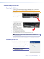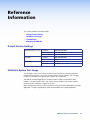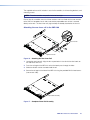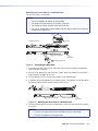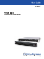
1
User Guide VN-Matrix® VNR 100 VN-Matrix Single Channel Recorder 68-2237-01 Rev. A 05 13 Safety Instructions Safety Instructions • English WARNING: This symbol, D, when used on the product, is intended to alert the user of the presence of uninsulated dangerous voltage within the product’s enclosure that may present a risk of electric shock. ATTENTION: This symbol, I, when used on the product, is intended to alert the user of important operating and maintenance (servicing) instructions in the literature provided with the equipment. Chinese Simplified(简体中文) 警告:D产品上的这个标志意在警告用户该产品机壳内有暴露的危险 电压,有触电危险。 注 意 :I 产 品 上 的 这 个 标 志 意 在 提 示 用 户 设 备 随 附 的 用 户 手 册 中 有 重要的操作和维护(维修)说明。 关于我们产品的安全指南、遵循的规范、EMI/EMF 的兼容性、无障碍 For information on safety guidelines, regulatory compliances, EMI/EMF compatibility, accessibility, and related topics, see the Extron Safety and Regulatory Compliance Guide, part number 68-290-01, on the Extron website, www.extron.com. 安全规范指南,产品编号 68-290-01。 Instructions de sécurité • Français Chinese Traditional(繁體中文) avertissement: Ce pictogramme, D, lorsqu’il est utilisé sur le produit, signale à l’utilisateur la présence à l’intérieur du boîtier du produit d’une tension électrique dangereuse susceptible de provoquer un choc électrique. attention: Ce pictogramme, I, lorsqu’il est utilisé sur le produit, signale à l’utilisateur des instructions d’utilisation ou de maintenance importantes qui se trouvent dans la documentation fournie avec le matériel. 使用的特性等相关内容,敬请访问 Extron 网站 www.extron.cn,参见 Extron 警告: D若產品上使用此符號,是為了提醒使用者,產品機殼內存在著 可能會導致觸電之風險的未絕緣危險電壓。 注意I 若產品上使用此符號,是為了提醒使用者。 有關安全性指導方針、法規遵守、EMI/EMF 相容性、存取範圍和相關主題的詳細 資訊,請瀏覽 Extron 網站:www.extron.cn,然後參閱《Extron 安全性與法規 遵守手冊》,準則編號 68-290-01。 Pour en savoir plus sur les règles de sécurité, la conformité à la réglementation, la compatibilité EMI/EMF, l’accessibilité, et autres sujets connexes, lisez les informations de sécurité et de conformité Extron, réf. 68-290-01, sur le site Extron, www.extron.fr. Sicherheitsanweisungen • Deutsch warnung: Dieses Symbol D auf dem Produkt soll den Benutzer darauf aufmerksam machen, dass im Inneren des Gehäuses dieses Produktes gefährliche Spannungen herrschen, die nicht isoliert sind und die einen elektrischen Schlag verursachen können. Vorsicht: Dieses Symbol I auf dem Produkt soll dem Benutzer in der im Lieferumfang enthaltenen Dokumentation besonders wichtige Hinweise zur Bedienung und Wartung (Instandhaltung) geben. Weitere Informationen über die Sicherheitsrichtlinien, Produkthandhabung, EMI/EMF-Kompatibilität, Zugänglichkeit und verwandte Themen finden Sie in den Extron-Richtlinien für Sicherheit und Handhabung (Artikelnummer 68290-01) auf der Extron-Website, www.extron.de. Instrucciones de seguridad • Español ADVERTENCIA: Este símbolo, D, cuando se utiliza en el producto, avisa al usuario de la presencia de voltaje peligroso sin aislar dentro del producto, lo que puede representar un riesgo de descarga eléctrica. ATENCIÓN: Este símbolo, I, cuando se utiliza en el producto, avisa al usuario de la presencia de importantes instrucciones de uso y mantenimiento recogidas en la documentación proporcionada con el equipo. Para obtener información sobre directrices de seguridad, cumplimiento de normativas, compatibilidad electromagnética, accesibilidad y temas relacionados, consulte la Guía de cumplimiento de normativas y seguridad de Extron, referencia 68-290-01, en el sitio Web de Extron, www.extron.es. Japanese 警告: この記号 D が製品上に表示されている場合は、筐体内に絶縁されて いない高電圧が流れ、感電の危険があることを示しています。 I 注意: この記号 が製品上に表示されている場合は、本機の取扱説明書に記載されて いる重要な操作と保守(整備)の指示についてユーザーの注意を喚起するものです。 安全上のご注意、法令遵守、EMI/EMF適合性、その他の関連項目に ついては、エクストロンのウェブサイトwww.extron.jpより 『 Extron Safety and Regulatory Compliance Guide』 (P/N 68-290-01) をご覧く ださい。 Korean 경고: 이 기호 D, 가 제품에 사용될 경우, 제품의 인클로저 내에 있는 접지되지 않은 위험한 전류로 인해 사용자가 감전될 위험이 있음을 경고합니다. 주의: 이 기호 I, 가 제품에 사용될 경우, 장비와 함께 제공된 책자에 나와 있는 주요 운영 및 유지보수(정비) 지침을 경고합니다. 안전 가이드라인, 규제 준수, EMI/EMF 호환성, 접근성, 그리고 관련 항목에 대한 자세한 내용은 Extron 웹 사이트(www.extron.co.kr)의 Extron 안전 및 규제 준수 안내서, 68-290-01 조항을 참조하십시오. FCC Class A Notice This equipment has been tested and found to comply with the limits for a Class A digital device, pursuant to part 15 of the FCC rules. The Class A limits provide reasonable protection against harmful interference when the equipment is operated in a commercial environment. This equipment generates, uses, and can radiate radio frequency energy and, if not installed and used in accordance with the instruction manual, may cause harmful interference to radio communications. Operation of this equipment in a residential area is likely to cause interference; the user must correct the interference at his own expense. NOTE: For more information on safety guidelines, regulatory compliances, EMI/EMF compatibility, accessibility, and related topics, see the “Extron Safety and Regulatory Compliance Guide” on the Extron website. Specifications Availability Product specifications are available on the Extron website, www.extron.com. Copyright © 2013 Extron Electronics. All rights reserved. Trademarks All trademarks mentioned in this guide are the properties of their respective owners. The following registered trademarks(R), registered service marks(SM), and trademarks(TM) are the property of RGB Systems, Inc. or Extron Electronics: Registered Trademarks (®) AVTrac, Cable Cubby, CrossPoint, eBUS, EDID Manager, EDID Minder, Extron, Flat Field, GlobalViewer, Hideaway, Inline, IP Intercom, IP Link, Key Minder, LockIt, MediaLink, PoleVault, PowerCage, PURE3, Quantum, SoundField, SpeedSwitch, System Integrator, TouchLink, V‑Lock, VersaTools, VN‑Matrix, VoiceLift, WallVault, WindoWall Registered Service Mark(SM) : S3 Service Support Solutions Trademarks (™) AAP, AFL (Accu‑Rate Frame Lock), ADSP (Advanced Digital Sync Processing), AIS (Advanced Instruction Set), Auto‑Image, CDRS (Class D Ripple Suppression), DDSP (Digital Display Sync Processing), DMI (Dynamic Motion Interpolation), Driver Configurator, DSP Configurator, DSVP (Digital Sync Validation Processing), FastBite, FOXBOX, IP Intercom HelpDesk, MAAP, MicroDigital, ProDSP, QS‑FPC (QuickSwitch Front Panel Controller), Scope‑Trigger, SIS, Simple Instruction Set, Skew‑Free, SpeedMount, SpeedNav, Teamwork, Triple‑Action Switching, XTP, XTP Systems, XTRA, ZipCaddy, ZipClip Conventions Used in this Guide Notifications The following notifications are used in this guide: DANGER: A danger indicates a situation that will result in death or severe injury. WARNING: A warning indicates a situation that has the potential to result in death or severe injury. CAUTION: A caution indicates a situation that may result in minor injury. ATTENTION: Attention indicates a situation that may damage or destroy the product or associated equipment. NOTE: A note draws attention to important information. TIP: A tip provides a suggestion to make working with the application easier. Software Commands Commands are written in the fonts shown here: ^AR Merge Scene,,Op1 scene 1,1 ^B 51 ^W^C [01] R 0004 00300 00400 00800 00600 [02] 35 [17] [03] E X! *X1&* X2)* X2#* X2! CE} NOTE: For commands and examples of computer or device responses mentioned in this guide, the character “0” is used for the number zero and “O” represents the capital letter “o.” Computer responses and directory paths that do not have variables are written in the font shown here: Reply from 208.132.180.48: bytes=32 times=2ms TTL=32 C:\Program Files\Extron Variables are written in slanted form as shown here: ping xxx.xxx.xxx.xxx —t SOH R Data STX Command ETB ETX Selectable items, such as menu names, menu options, buttons, tabs, and field names are written in the font shown here: From the File menu, select New. Click the OK button. Contents Introduction............................................................ 1 Replacing the VNR 100 Drives................... 15 About the Guide.................................................. 1 About the VNR 100 Recorder.............................. 1 VNR 100 Drives............................................... 2 Application Diagram........................................ 2 Overview of Recorded Streams....................... 3 Overview of Stream Playback.......................... 3 Transport Protocols Used for Streaming.............. 3 Multicast RTP — An Overview......................... 4 Unicast RTP — An Overview........................... 5 Unicast TCP — An Overview........................... 5 Definitions............................................................ 6 Features.............................................................. 7 OS Drive Replacement Kit................................. 15 Replacing the OS Drive.................................. 15 Configuring the New Drive............................. 16 Media Drive Replacement Kit............................. 18 Replacing the Media Drive............................. 18 Configuring the New Drive............................. 18 Monitoring Free and Used Disk Space........... 19 Directory and File Structure............................ 19 Panels and Cabling............................................... 8 Rear Panel Features............................................ 8 Front Panel Cover................................................ 9 Front Panel Features............................................ 9 Reference Information............................... 20 Default Factory Settings..................................... 20 VN-Matrix System Port Usage........................... 20 Included Parts................................................... 22 Mounting the VNR 100...................................... 22 UL Guidelines for Rack Mounting................... 22 Rack Mounting Using Rack Rails................... 22 Configuration and Hardware Setup........ 11 Setup Overview................................................. 11 VNR 100 Power Up Procedure.......................... 12 VNR 100 Power Down Procedure..................... 12 Initial Configuration of the VNR 100................... 12 Getting Started with the Enterprise Controller.... 14 Technical Publications Standards and Styles VNR 100 • Introduction • Contents v VNR 100 • Contents vi Introduction This section provides an overview of the user guide for the Extron VNR 100 single channel recorder and covers the following topics: • About the Guide • About the VNR 100 Recorder • Transport Protocols Used for Streaming • Definitions • Features About the Guide This guide contains installation, configuration, and operating information for the VNR 100. In this guide: • The term “recorder” refers specifically to the VNR 100. • The term “codec” refers to a VN-Matrix device that acts as an encoder and decoder. • The term “stream” refers to multimedia that is constantly received by (and normally presented to) an end-user while being delivered by a VN-Matrix encoding device. • The term “element” refers to the video or graphics, audio, data, and whiteboard (user data) content that is contained within a stream. About the VNR 100 Recorder The VNR 100 recorder is a network appliance capable of recording PURE3 video, audio, and data streams from VN-Matrix codecs and encoders. Multiple VNR 100 units can be configured together into systems to record and play back multiple, synchronized PURE3 streams. The recorder is able to play and control a previously recorded file while simultaneously recording a new file, with a sustained aggregate bit rate of 150 Mbps. The VNR 100 is also able to replay, with time slip, a file that is still being recorded. One or more VNR 100 recorders can be used in a VN-Matrix system. The system must be under the control of an Extron VNM Enterprise Controller, whether the system contains a single VNR 100 recorder or multiple recorders. Controlling multiple recorder devices or channels from a single master unit allows: • Support for common transport controls for record and playback of grouped channels. • Support for directory and file management of grouped recordings and playback. Multi-channel systems are facilitated by maintaining full stream synchronization of multiple recorder devices across all stream elements (video, audio, data, and whiteboard) at all playback speeds in forward and reverse directions. The recorder uses a network storage architecture, which makes the system highly scalable and flexible. <Product Name> VNR 100 • <Section • Introduction Title> 1 The VNR 100 recorder is fully compatible with existing VNM Matrix products, including the: • Extron 5-channel VN-Matrix recorder • Extron VN-Matrix 2xx and 3xx codecs • Extron VN-Matrix software decoder • Extron VN-Matrix Enterprise Controller • Extron VNS 104 Multi-Stream decoding software VNR 100 Drives The VNR 100 has two replaceable drives: • Operating system (OS) drive — the OS drive contains the VNR 100 operating system. • Media drive — the media drive contains the video, audio, data, and whiteboard information files that have been recorded by the VNR 100. Both these drives can be replaced easily. Replacing the media drive does not require any device specific data to be updated on the OS drive. For complete instructions on replacing the drives, see OS Drive Replacement Kit (page 15) and Media Drive Replacement Kit (page 18). Application Diagram TouchLink™ Touchpanel External User Control VN-Matrix VNR 100 Recorder VNR 100 Recorder Browser Based User Control Network VNM Enterprise Controller VNR 100 Recorder LAN-1 LAN-2 STATUS LAN-1 LAN-2 STATUS VN-MATRIX 225 SERIES VN-MATRIX 225 SERIES RGB/DVI OVER IP RGB/DVI OVER IP LAN-1 LAN-2 STATUS LAN-1 LAN-2 STATUS VN-MATRIX 225 SERIES VN-MATRIX 225 SERIES RGB/DVI OVER IP RGB/DVI OVER IP LAN-1 LAN-2 STATUS LAN-1 LAN-2 STATUS VN-MATRIX 225 SERIES RGB/DVI OVER IP Multiple VNM 200 and 225 Series Encoders (or CODECs configured as encoders) Figure 1. VN-Matrix VNR 100 Recorder Multicast Enabled Network VN-MATRIX 225 SERIES RGB/DVI OVER IP Multiple VNM 200 and 225 Series Decoders (or CODECs configured as decoders) Example of a System using the Extron VNR 100 VNR 100 • Introduction 2 Overview of Recorded Streams Encoders convert video signals to highly compressed signals that can be transferred over a network. • The VNR 100 records the compressed signals from the network, without further processing. • As a minimum, each recording contains a video element. • A recording may also include elements containing audio, data, and whiteboard information (if these are present and enabled at the encoder). If these are selected for storage, each element is stored as an individual file within the same directory. Overview of Stream Playback • The VNR 100 plays back saved data without processing. It is already in a highly compressed format that can be transferred over a network. • When a recording that contains multiple elements is selected for playback, all the necessary files are loaded. • The video content is always played back. • When present, audio, data, and whiteboard elements may be enabled or disabled for playback. If they are enabled, the audio, whiteboard, and data elements are always slaved to the video stream. Decoders take the highly compressed signals from the network and reconvert them to the uncompressed format required by a display device. Transport Protocols Used for Streaming Source data from a VN-Matrix encoder can be distributed to multiple displays or decoders (one-to-many) or to a single display or decoder (point-to-point). A previously recorded stream can be distributed in the same way and, as the source of an encoded stream, the recorder may be thought of as an encoder in this context. A stream may be transported over the network from the source (encoder, recorded stream) to the display (decoder) using one of three methods: • Multicast Real-time Transport Protocol (RTP) • Unicast Real-time Transport Protocol (RTP) • Unicast Transmission Control Protocol (TCP) By default, the VNR 100 recorder provides a choice of unicast RTP or unicast TCP transport protocols. A multicast transport protocol may be configured if required (see the Enterprise Controller User Guide). NOTES: • During playback of a recorded stream, the transport protocol can be TCP, RTP, or RTP Multicast. The protocol is specified on the VNM Enterprise Controller. • When a stream is recording, the VNR 100 may be considered as a display (decoder) device. VNR 100 • Introduction 3 Multicast RTP — An Overview Multicast RTP allows a source to be displayed on multiple displays. This method uses a real-time variation of UDP (User Datagram Protocol) called RTP (Real-time Transport Protocol). RTP LAN-1 LAN-2 STATUS Network RTP LAN-1 LAN-2 STATUS VN-MATRIX 225 SERIES VN-MATRIX 225 SERIES RGB/DVI OVER IP RGB/DVI OVER IP Encoder sends data using RTP to a multicast group. RTP LAN-1 LAN-2 STATUS SOURCE VN-MATRIX 225 SERIES RGB/DVI OVER IP RTP LAN-1 LAN-2 STATUS VN-MATRIX 225 SERIES RGB/DVI OVER IP RTP LAN-1 LAN-2 STATUS VN-MATRIX 225 SERIES RGB/DVI OVER IP RTP Multiple decoders can be part of the multicast group. Figure 2. Multicast RTP Streaming DISPLAY(S) The source encoder uses RTP to send data to a multicast group. The source does not need to know the IP address of the decoders that are using the source. RTP provides very low latency which is important for video streaming. Unlike other protocols, RTP packets include a time stamp. If packets are received in the wrong order, they are sorted into the correct order for display or discarded if the time stamp is out-of-date. However, because RTP is a connectionless protocol, data delivery is not guaranteed. When data packets are lost (for example, due to excessive network traffic), the decoder devices carefully manage the data stream to minimize any image disruption. VNR 100 • Introduction 4 Unicast RTP — An Overview Similar to multicast RTP, this method uses a real-time variation of UDP protocol, called unicast RTP. This method can be used where the network infrastructure does not support multicast traffic. Typically, this protocol is used for point-to-point configuration (single source to single display), but can be configured to use up to a maximum of four displays. NOTE: The encoder sends an individual stream to each decoder. This means that the total bandwidth of the VN-Matrix system increases as more decoders are added. RTP 1-4 LAN-1 LAN-2 STATUS Network RTP 1 LAN-1 LAN-2 STATUS VN-MATRIX 225 SERIES VN-MATRIX 225 SERIES RGB/DVI OVER IP RGB/DVI OVER IP Encoder sends data using RTP to up to 4 specified decoders. RTP 2 LAN-1 LAN-2 STATUS SOURCE VN-MATRIX 225 SERIES RGB/DVI OVER IP RTP 3 LAN-1 LAN-2 STATUS VN-MATRIX 225 SERIES RGB/DVI OVER IP RTP 4 LAN-1 LAN-2 STATUS VN-MATRIX 225 SERIES RGB/DVI OVER IP DISPLAYS Figure 3. Unicast RTP Streaming RTP provides very low latency which is important for video streaming. Unlike other protocols, RTP packets include a time stamp. If packets are received in the wrong order, they are sorted into the correct order for display or discarded if the time stamp is out-of-date. However, because RTP is a connectionless protocol, data delivery is not guaranteed. When data packets are lost (for example, due to excessive network traffic), the decoder devices carefully manage the data stream to minimize any image disruption. Unicast TCP — An Overview This method transports data using standard TCP (Transport Control Protocol) and should only be used for single point-to-point transfer of data. TCP is a connection-based protocol and, therefore, data is guaranteed to be delivered. However, in the event of excessive network traffic, delivery may be delayed which will impact real-time performance. TCP LAN-1 LAN-2 STATUS Network VN-MATRIX 225 SERIES RGB/DVI OVER IP Encoder SOURCE TCP LAN-1 LAN-2 STATUS VN-MATRIX 225 SERIES RGB/DVI OVER IP Decoder makes a TCP connection with a specified encoder. DISPLAY Figure 4. Unicast TCP Streaming The decoder defines which source to connect to. Other than defining an IP address and source type (if required), no special source encoder setup is required. VNR 100 • Introduction 5 Definitions PURE3 — PURE3 is specifically designed for network transmission of real time media (such as video or graphics, audio, data, and whiteboard elements). It features both spatial and temporal image compression, which allows for efficient bandwidth usage and eliminates the need for forward error correction. • PURE3 streams always contain video or graphic elements. • PURE3 streams may contain audio, data, and whiteboard elements that are associated with the video and graphic elements. Streaming media (stream) — This term refers to multimedia that is constantly received by (and normally presented to) an end-user while being delivered by a streaming provider. Internet television is a commonly streamed medium. Streaming media (stream) in this guide refers to a PURE3 media stream that is produced by a VN-Matrix encoding device. Element — This term refers to the video, graphics, audio, (user) data, and whiteboard (annotation data) content that is contained within a stream. Device license — This term refers to the number of licensed features that are available on a device within a VN-Matrix system. All devices contain a default license that offers a default level of functionality. See the VNM Enterprise Controller User Guide (at www.extron.com) for information about device licenses. Controller license — This term refers to the license that is supplied to the VNM Enterprise Controller. See the VNM Enterprise Controller User Guide for information about device licenses. (User) Data — This refers to the transfer of user data between an encoder and a decoder. User data is created at the encoder, placed into the PURE3 stream, and sent to the decoder. The data is received in the same form that it was transmitted. This method of data transfer is unidirectional and can only be sent from an encoder to a decoder. Whiteboard (wb) data — Also known as annotation data, whiteboard data outputs text and simple pointer annotation onto local displays that are connected to VN-Matrix encoders or decoders. This type of data is bidirectional, which allows a decoder to send whiteboard data to an encoder. VNR 100 • Introduction 6 Features Simultaneously record and play back VN-Matrix AV streams — uses customer assets more effectively by allowing free use of imaging sources independent of playback and review Time-shift playback capabilities support time slip or chase play — offers flexible timing for playback of recorded events to accommodate local schedules Transport controls include: play, pause, and variable speed playback at 2x, 4x, and 8x speeds in forward or reverse as well as single frame advance in forward or reverse — allows time-efficient review and scanning over recorded content System scalability — create multi-channel recording systems using multiple VNR 100 units — flexible to apply in a wide range of applications; develop recording systems with few or many audio and video channels System synchronization — synchronize playback across multiple VNR 100 units — supports lip sync, genlocked decoding, scaled playback across multiple VNR 100 units, synchronization of recorded external ancillary data to audio and video streams, and the ability to support recording and playback of videowalls, or multi-display systems PURE3 codec — provides visually lossless compression, efficient bit rates, and absolute frame encoding supporting high quality content, lip sync, synchronization of multi-screen playback, and playback transport controls for efficient and accurate visual documentation Removable storage — provides flexibility to secure recorded data in sensitive or secret applications Replacement media drive and operating system drive available — use in data‑sensitive applications where independent storage is required to record different events Compatible with VN-Matrix 200, 225, and 300 series and VN-Matrix Software Decoders — maintains value of existing and investments in Extron VN‑Matrix products VNR 100 • Introduction 7 Panels and Cabling This section provides information on: • Rear Panel Features • Front Panel Cover • Front Panel Features Rear Panel Features b d a Figure 5. c d e f g h VNR 100 Rear Panel a AC power connector — use a standard IEC power cord to connect the recorder to a 100 to 240 VAC, 50 or 60 Hz power source. b PS/2 port for mouse (optional) — connect a PS/2 mouse to this port, if required. c PS/2 port for computer keyboard (optional) — connect a PS/2 keyboard to this port, if required. d USB ports (2) — used to connect a mouse and keyboard for the initial configuration. There are a total of four USB inputs: two rear panel and two front panel. e RS-232 control port — use an Extron cable (not provided) to connect the VNR 100 to a control PC. f VGA output connector — connect a local VGA monitor to this output. g Ethernet port 0 (eth0) — use an RJ-45 cable to connect this port to the primary network (the VN-Matrix network). h Ethernet port 1 (eth1) — is not functional. Do not connect this port to a network. VNR 100 • Panels and Cabling 8 Front Panel Cover The front panel has a lockable cover to prevent unauthorized access to the removable drives. The cover has five light tubes that allow the signals from the front panel LEDs to be seen when the cover is in place. Light Tubes Projections (2 on each end) VN-Matrix VNR 100 Recorder Release Catch Lock Figure 6. VNR 100 Front Panel Cover To install the front cover: 1. Ensure the Lock is in the open position ( undo the lock. ). If necessary, use the provided key to 2. Holding the cover at a slight angle, slide the two projections on the left side of the cover into the holes on the inside surface of the handle (a in the figure below). 3. Press the release catch inwards to retract the two projections on the right side of the cover and slide the cover into place. 4. Release the catch to allow the two projections to fit into the holes on the surface of the handle. 5. If required, use the key to lock the cover in place. Handle VN-Matrix VNR 100 Recorder Figure 7. VNR 100 Front Panel Cover, installed Remove the cover by reversing these steps. Front Panel Features b a h Figure 8. i c c j d e fg a j VNR 100 Front Panel The front panel has a removable bezel, which can be locked in place to secure the media drives. When the bezel is locked in place the DVD player, USB ports, and serial ports are not available for use. NOTE: It is not necessary to access the front panel during normal operation of the VNR 100. a Handles (2) — the VNR 100 is mounted on sliding rails in a standard rack. The handles allow the unit to be pulled in and out of the rack on the rails. They are also used to secure the front panel bezel. b CD and DVD drive — used for system updates or software installation. VNR 100 • Panels and Cabling 9 c USB ports (2) — used to connect a mouse and keyboard for the initial configuration. There are a total of four USB inputs: two rear panel and two front panel. d RS-232 Comm port — Insert 9-pin RS-232 cable. e Status LEDs — five LEDs, which provide information about: i Overtemperature 2 1 Network Activity (2) Network Activity (1) Drive Activity Power a. The Overtemperature (i) LED flashes yellow when a fan has failed. It lights yellow solidly when the internal temperature is too high (the ambient temperature may be too high or the flow of air to the fan may be obstructed). b. Network 2 is not active, so this LED does not light. c. The Network Activity (1) LED flashes green when there is activity on network 1. d. The Drive Activity LED flashes yellow when the hard drive is in use. e. The Power LED lights green when the unit is receiving power. f Reset button — use this button to reboot the VNR 100. g Power button — used to apply or turn off the main power. When the main power is turned off, standby power is actively supplied to the recorder. h OS drive — houses the solid state operating system drive (removable). i Media drive — houses the media drive (removable). j Spare drive bays (2) — must not have drives fitted. ATTENTION: Do not remove the OS or Media drive when the VNR 100 is powered on. VNR 100 • Panels and Cabling 10 Configuration and Hardware Setup This section provides information on how to perform the initial configuration of the VNR 100 so that it will work over the Ethernet with a network that is controlled by an Enterprise Controller. Topics that are covered in this section include: • Setup Overview • VNR 100 Power Up Procedure • VNR 100 Power Down Procedure • Initial Configuration of the VNR 100 • Getting Started with the Enterprise Controller Setup Overview NOTE: if the VNR 100 recorder is rack mounted, access to the rear panel may be restricted. Connect all cables at the same time as the unit is mounted. 1. Mount the VNR 100 recorder in a suitable location (see Mounting the VNR 100 on page 22). 2. Connect a standard IEC power cord to the rear panel power connector (a in figure 5). 3. Connect the VNR 100 to a network, using the rear panel Ethernet port 0 (g in figure 5). The VNR 100 must be controlled by an VNM Enterprise Controller connected to the network. 4. Power on the VNR 100 (see VNR 100 Power Up Procedure on page 12). 5. Use a computer on the same network as the VNR 100 to carry out the initial configuration (see Initial Configuration of the VNR 100 on page 12). This initial configuration makes the VNR 100 available to a VNM Enterprise Controller on the same network. 6. If it becomes necessary to power down the VNR 100 recorder, see VNR 100 Power Down Procedure on page 12. VNR 100 • Configuration and Hardware Setup 11 VNR 100 Power Up Procedure NOTE: Before turning on the VNR 100, ensure all necessary devices are connected correctly and powered up. Power up the VNR 100 by pressing the Power button (g in figure 8). The VNR 100 boots up. VNR 100 Power Down Procedure Power off the VNR 100 by pressing and releasing the front panel power button. The recorder takes approximately 20 to 30 seconds to power-down. Initial Configuration of the VNR 100 The initial configuration of the VNR 100 allows it to connect to the Enterprise Controller. Once it is integrated into the Enterprise Controller network, the VNR 100 will be completely controlled by the Enterprise Controller. By default, the VNR 100 is pre-configured with the following network settings: • IP Address: 192.168.254.254 • Subnet Mask: 255.255.225.0 • Port Number: 8080 You will need to contact your network administrator to find out the IP address for the Enterprise Controller. To perform the initial configuration, follow these instructions: 1. Initial configuration is through the browser of a computer connected to the same network as the VNR 100. In the browser address bar, enter the IP address of the recorder followed by a colon and the port number (for example: 192.168.254.254:8080). The login page opens: Figure 9. VNR 100 Login to Web Page 2. Enter the Username and Password. NOTE: By default, the Username and the Password are both config. VNR 100 • Configuration and Hardware Setup 12 3. Click Login. The VNR 100 Recorder Settings page opens: Logout VNMatrix recorder settings Network settings [eth0] IP Address 192.168.254.254 Subnet Mask 255.255.255.0 Gateway 192.168.254.253 Serial 1111999 Controller IP 192.168.254.254 Controller port 5432 MTU 1500 Recorder settings User settings New password Confirm New password Data disk Umount status: Disk free space: Format mounted to /home/matrix_rec/Recording_Files 19GB->98% used formated to ext3 Apply Changes Cancel Changes Figure 10. VNR 100 Web Page 4. Enter the IP Address, Subnet Mask, and Gateway address of the recorder. 5. Enter the Controller IP address, Controller port number and maximum transmission unit (MTU) setting of the controller. 6. Enter a New password and Confirm New password. 7. Click Apply Changes to save the settings (or click Cancel Changes to exit without saving the information). ATTENTION: There is no indication whether you have been successful or unsuccessful in connecting to the Enterprise Controller. To verify that the recorder has linked to the controller, you must log on to the controller and ensure that the recorder is in the device list. IP Address and Subnet mask — are assigned to the ETH0 NIC on the VNR100. Gateway — is the IP address of the gateway that is assigned to the ETH0 NIC on the VNR100. If no gateway exists, the IP address should be the same as the system contoller. Controller IP Address — is the IP address of the Enterprise Controller used to control the VNR100. Controller Port — is the port number is used by all VN_Matrix devices to communicate with the Enterprise Controller. The value should only be changed if the Enterprise Controller has been configured to accept communications on a different port number. Under normal circumstances the setting should remain at the default setting (5432). Maximum Transmission Unit (MTU) — is used to set the packet size, in bytes, that is used to transmit data over the network. The default is 1500 bytes. This setting is for advanced use only. Under normal circumstance do not change this value from the default value. If the MTU value is incorrectly set, the MATRIX system may malfunction. New password — Change the default password for the config account if required. The User account name cannot be changed. Data (media) disk —This area provides information about the media drive on the VNR 100. For full instructions on replacing the media drive, please see the VNR 100 Media Drive Replacement Kit Installation Guide, at www.extron.com. VNR 100 • Configuration and Hardware Setup 13 Getting Started with the Enterprise Controller The VNR 100 Single channel recorder is controlled by the VNM Enterprise Controller, which is used to configure and manage all Matrix devices in the system. VNR 100 devices are used with VN-Matrix encoders and decoders to record and play back PURE3 streams. VNR 100 devices may be controlled singly or in groups to enable recording and playback of more than one stream. System settings are configured as presets that may then be recalled from either the VNM Enterprise Controller WEB UI or from an external control system connected to the VNM Enterprise Controller using the HLI command protocol. 1. Use a PC on the same network as the VNM Enterprise Controller to access the website for the controller. Enter the IP address for the controller in the address bar. The controller Login screen opens: Figure 11. Enterprise Controller Login Screen 2. Enter the Username and Password. 3. Click Login. The Enterprise Controller Device List opens: Figure 12. Enterprise Controller Device List 4. Check the box next to the VNR 100 recorder. A series of action buttons appear at the bottom of the screen: Figure 13. Enterprise Controller Device List Action Buttons Use the Enterprise Controller User Guide (at www.extron.com) for complete information about configuring and using the VNR 100 recorder. VNR 100 • Configuration and Hardware Setup 14 Replacing the VNR 100 Drives There are two optional drive replacement kits for the Extron VNR 100: • OS Drive Replacement Kit • Media Drive Replacement Kit The drives allow the recorder to be moved between secure areas without compromising confidential data. The media drive kit also offers a convenient way to archive materials. There are four drive bays on the front panel of the VNR 100. From left to right, they are numbered 0 - 3. The OS drive is number 0 and the media drive is number 1. c OS Drive (drive #0) b a Media Drive (drive #1) Figure 14. Media Drive and OS Drive OS Drive Replacement Kit Replacing the OS Drive ATTENTION: Never remove or insert the drive while the unit is powered on. NOTES: • The replacement drive does not have a default IP address assigned. This must be set by the user. • The OS drive is licensed to run only on the VNR 100 for which it was supplied and cannot be used with any other VNR 100 unit. • A label fixed to the top of the drive shows the serial number of the VNR 100 for which it is intended to be used. 1. Switch the recorder off by pressing and holding down the power switch (figure 14, a) until the LEDs (figure 14, b) flash red and then go out. 2. Unplug the recorder. 3. Press the red catch. The lever arm is released (see the figure on the right). VNR 100 • Replacing the VNR 100 Drives 15 4. Swing the lever arm out until it is perpendicular to the front of the drive caddy (as shown in the figure to the right). Use the arm to pull the caddy out of the drive bay. 5. Remove the drive. There are no screws to be removed or cable connections to be undone. 6. Insert the new drive into the drive bay. 7. Push the caddy back into the recorder. 8. Swing the lever arm back until it clicks into place behind the catch. ATTENTION: Do not power on the unit at this time. Configuring the New Drive 1. Attach a mouse to the rear panel PS/2 mouse port (e) and a keyboard to the rear panel PS/2 keyboard port (f). Alternatively, you may connect the mouse and keyboard to the front panel USB ports (c in the figure on page 15) or the rear panel USB ports (d). e d 2. Connect a VGA monitor to the rear panel port (g). f d g 3. Power on the recorder by pressing the front panel power switch (a in figure 14 on page 15). 4. Power on the monitor. The login screen is displayed. 5. Enter the Username and Password. NOTE: By default, the Username is matrix_rec and the Password is matrix. 6. From the menu bar on the desktop, select Applications > Internet > Firefox Web Browser. VNR 100 • Replacing the VNR 100 Drives 16 7. In the browser address bar, enter the IP address of the recorder followed by a colon and the port number (127.0.0.1:8080). The login page opens (see the figure to the right). 8. Enter the Username and Password. NOTE: By default, the Username and Password are both config. 9. Click Login. The VNR 100 Recorder Settings page opens (see the figure to the right). 10. Set the Network Settings and Recorder Settings as required (default values are shown). Logout VNMatrix recorder settings 11. Click Apply Changes. Network settings [eth0] 12. Logout of the config screen. IP Address Subnet Mask 255.255.0.0 13. Power down the unit. Gateway 192.168.254.253 14. Remove the mouse, keyboard, and monitor. Serial 1111999 192.168.254.254 Recorder settings Controller IP 192.168.254.254 Controller port 5432 MTU 1500 User settings New password Confirm New password Data disk Umount status: Disk free space: Format mounted to /home/matrix_rec/Recording_Files 19GB->98% used formated to ext3 Apply Changes Cancel Changes VNR 100 • Replacing the VNR 100 Drives 17 Media Drive Replacement Kit Replacing the Media Drive 1. If necessary, switch the recorder off by pressing and holding down the power switch (figure 14, a) until the LEDs (figure 14, b) flash red and then go out. ATTENTION: Never remove or insert the drive while the unit is powered on. 2. Unplug the recorder. 3. Press the red catch (see the figure to the right). The lever arm is released. 4. Swing the lever arm out until it is perpendicular to the front of the drive caddy (see the figure to ther right). Use the arm to pull the caddy out of the drive bay. 5. Remove the drive. There are no screws to be removed or cable connections to be undone. 6. Insert the new drive into the drive bay. 7. Push the caddy back into the recorder. 8. Swing the lever arm back until it clicks into place behind the catch. NOTE: When the new drive is correctly seated, all necessary connections are automatically formed. 9. Reconnect the power to the VNR 100 and power it on by pressing the power switch. Configuring the New Drive Initial configuration is through the browser of a computer connected to the same network as the VNR 100. 1. In the browser address bar, enter the IP address of the recorder followed by a colon and the port number (for example 192.168.254.254:8080). The login page opens (see the figure to the right). 2. Enter the Username and Password. NOTE: By default, the Username and Password are both config. VNR 100 • Replacing the VNR 100 Drives 18 3. Click Login. The VNR 100 Recorder Settings page opens (see the figure to the right). Once mounted, the capacity of the new drive will be shown under Disk free space. This takes a few seconds. 4. If you are inserting a blank drive, click Format. ATTENTION: When inserting a drive that contains previously recorded content, do not use the Format option as this will remove all data. Logout VNMatrix recorder settings Network settings [eth0] IP Address 192.168.254.254 Subnet Mask 255.255.0.0 Gateway 192.168.254.253 Serial 1111999 Recorder settings Controller IP 192.168.254.254 Controller port 5432 MTU 1500 User settings When the formatting is complete, the message formated to ext3 will appear next to the Format button. 5. Click Apply Changes. New password Confirm New password Data disk Umount status: Disk free space: Format mounted to /home/matrix_rec/Recording_Files 19GB->98% used formated to ext3 Apply Changes 6. Logout of the config screen. Cancel Changes Monitoring Free and Used Disk Space To monitor the amount of free disk space and the percentage of disk space used, see the Data Disk information on the VNR 100 web page (see the figure above). Directory and File Structure Use the Enterprise Controller website to view the directory and file structure of the VNR 100 media disk. 1. Enter the IP address of the Enterprise Controller in the address bar of your browser. 2. At the login screen, enter the username and password. 3. If necessary, click on the Devices tab of the Enterprise Controller web page. 4. Select the VNR 100 of interest from the list of devices. 5. Click Recorder in the Action buttons at the bottom of the screen. A popup window opens showing the home directory for the recorder. 6. Click on the directory icon to show the files contained in the directory. Figure 15. Recorder File Structure VNR 100 • Replacing the VNR 100 Drives 19 Reference Information This section provides information about: • Default Factory Settings • VN-Matrix Port Usage • Included Parts • Mounting the VNR 100 Default Factory Settings Network settings (ETH0) Controller Configuration IP address 192.168.254.254 Subnet mask 255.255.255.0 Gateway address 192.168.254.253 IP address 192.168.254.254 Port 5432 User name config Password config VN-Matrix System Port Usage The VN-Matrix system uses a variety of network port numbers for streaming and intercommunication functions. Just as the universal “telnet” function typically uses TCP port number 23, VN-Matrix uses specific port numbers for its operation. The table on the following page lists the port numbers used by the VN-Matrix series products. The port numbers are, in most cases, for the sender. Port numbers used for receiving are less important in regards to security. When configuring a network, make sure it allows traffic on the ports required for your given application. The ports highlighted in yellow accommodate most simple applications. VNR 100 • Reference Information 20 Port Transport Usage 69 UDP TFTP Server, used for firmware upgrades 80 TCP HTTP data. Value is user definable; the default is 80. Used to communicate between the web browser and the Enterprise Controller 554 TCP Real-time streaming protocol (RTSP) server. 5432 UDP Enterprise Controller outgoing and incoming control messages. Value is user definable; the default is 5432. Only used on the device acting as controller to communicate with other VN-Matrix devices 5555 TCP Old XML interface and old VN-Matrix recorder software application. No longer used. 9998 TCP Command Line Interface (CLI) messages. Used to telnet to the controller for sending text-based control commands. 9999 TCP Deprecated: Old remote control server, replaced by CLI (port 9998). 23 TCP Telnet (can be disabled). 161 UDP Used for simple network management protocol (SNMP) alarm access. 199 TCP Used for simple network management protocol (SNMP) alarm access. 4002 TCP Source stream information. Used to telnet to the VN-Matrix decoder to view information about the source it is decoding. 5002 TCP Serial port bidirectional protocol (not data channel streaming). 6666 TCP Keyboard and mouse forwarding. 7777 UDP Upgrade daemon, local access only. 8000-8098 (even) UDP RTP unicast or RTP multicast audio, video, whiteboard, and data streams. Controller selects port number, starting at 8000. This is the port number of the destination (receiver). 8001-8099 (odd) UDP RTCP channel for audio, video, whiteboard, and data streams. Grouped with the even-numbered stream (8000 with 8001, 8002 with 8003, and so on). This is the port number of the destination (receiver). 8000 TCP Video streams. This is the port number of the source (sender). 8100 TCP Audio streams. This is the port number of the source (sender). 8200 TCP Whiteboard streams. This is the port number of the source (sender). 8201 TCP Data streams. This is the port number of the source (sender). 9000 TCP HSI interface if using ThorDebug. 9001 UDP VN-Matrix outgoing and incoming control messages. Communicates with port 5432 (or the user-defined port number) on the Enterprise Controller. 9002 UDP Default port for collecting UDP traffic for data-transport. Value is user‑definable. 9996 TCP HLI server port. 9997 TCP Annotation server port. NOTE: The ports highlighted in yellow accommodate most simple applications. VNR 100 • Reference Information 21 Included Parts Description Part Number VNR 100 Recorder 60-1291-01 Rack mounting kit VNR 100 Setup Guide Mounting the VNR 100 This section provides information on installing the VNR 100 into a rack cabinet. Rack installation requires the use of the provided rack mount kit. UL Guidelines for Rack Mounting The following Underwriters Laboratories (UL) guidelines are relevant to the safe installation of these products in a rack: 1. Elevated operating ambient temperature — If the unit is installed in a closed or multi-unit rack assembly, the operating ambient temperature of the rack environment may be greater than room ambient temperature. Therefore, install the equipment in an environment compatible with the maximum ambient temperature (TMA: +122 °F, +50 °C) specified by Extron. 2. Reduced air flow — Install the equipment in the rack so that the equipment gets adequate air flow for safe operation. 3. Mechanical loading — Mount the equipment in the rack so that uneven mechanical loading does not create a hazardous condition. 4. Circuit overloading — Connect the equipment to the supply circuit and consider the effect that circuit overloading might have on overcurrent protection and supply wiring. Consider the equipment nameplate ratings when addressing this concern. 5. Reliable earthing (grounding) — Maintain reliable grounding of rack-mounted equipment. Pay particular attention to supply connections other than direct connections to the branch circuit (such as the use of power strips). Rack Mounting Using Rack Rails The rack mounting kit is used to mount the VNR 100 in a Telco rack or a standard 19 inch (48.3 cm) wide rack with four vertical posts, one in each corner. ATTENTION: • When multiple units are mounted in the rack, load the rack from the bottom to the top, with the heaviest unit at the bottom. • If this is the only unit mounted in the rack, it should be mounted at the bottom. • With the rack rails collapsed, this unit requires a minimum rack depth of 25.5 inches (64.8 cm). • The total room required with the rack rails fully expanded, is 33.5 inches (85.1 cm). VNR 100 • Reference Information 22 The supplied rack mount kit includes 2 sets of rail assemblies, 6 rail mounting brackets, and mounting screws. NOTE: The rail assemblies are specific for the left and right. Each of the rail assemblies consists of three sections: two inner fixed rails that are secured to the VNR 100 recorder chassis and a two-section expandable rack rail that is secured directly to the rack. The front inner rails (right and left) are already attached to the chassis. Attaching the rear inner rail to the VNR 100 2 Rear Inner Rail 4 1 Front Inner Rail Figure 16. Attaching the Rear Inner Rail 1. Locate the rear inner rails. Align the four square holes in the rail with the four hooks on the side of the VNR 100. 2. Press the rail against the VNR 100 so that the hooks pass through the holes. 3. Slide the rail back so that the hooks hold the rail. 4. Secure the rail against the side of the VNR 100 using the provided M4 flat head screws (two on each side). Completed Rail Assembly Figure 17. Completed Inner Rail Assembly VNR 100 • Reference Information 23 Attaching the rack rails to a standard rack The rack rails come in two sections. NOTES: • The rail assemblies are specific for left and right. • The longer rail section attaches to the front of the rack. • The shorter rail section attaches to the rear of the rack. • The rear rail section goes to the outside of the front section (closer to the rack and further from the VNR 100). Stud 1 Rack Mounting Rail Rail Slot 3 2 Adjust Sliding Rail End Flange 4 Rail Mounting Brackets Figure 18. Assembling the Rack Rails 1. Assemble rack rail by pressing the stud of the rear rail section through the expanded hole of the front rail section. 2. With the stud seated in the slot of the front section, adjust the sliding rail until the total length matches the depth of the rack. 3. Use the locking screws to secure the assembly at the required length. 4. If required, rail mounting brackets (up to three on each rail assembly) can be secured to the bracket mounts on the outside surface of the rack rail. Rack Mounting Rail 5 5 Adjust Sliding Rail Rail Mounting Brackets End Flange Figure 19. Mounting the Rack Rails to a Standard Rack 5. Place the flanges against the front and back posts of the rack and secure the assembly to the rack. NOTES: • Ensure that the right and left side assemblies are at the same height. • Ensure the rail guides are facing forwards. VNR 100 • Reference Information 24 Attaching the rack rails to a Telco rack The Telco rack has one vertical post in the middle of each side. Outer Rail Assembly 2 2 Rail Mounting Brackets Rack Mounting Rail Figure 20. Attaching Rack Rails to a Telco Rack 1. Assemble the rack rail as described in the section above. 2. Secure two rail mounting brackets to each rail assembly. 3. Align the flanges of the rail mounting brackets with the vertical posts of the Telco rack. 4. Secure the rail assemblies to the Telco rack with the provided mounting screws. VNR 100 • Reference Information 25 Installing the VNR 100 into the rack By now, you must have the rails attached to both the VNR 100 chassis and to the rack. ATTENTION: Do not pick up the VNR 100 by the front handles. These are designed only for pulling the recorder from the rack. Outer Rail Assembly 2 2 Rail Mounting Brackets Rack Mounting Rail Locking Tabs Inner Rail Assembly Figure 21. Mounting the VNR 100 on the Rack Rails 1. Align the rear of the VNR 100 chassis with the front of the rack rails. 2. Slide the chassis into the rack rails, applying equal pressure to both sides. NOTE: You may need to depress the locking tabs while inserting the chassis. When the VNR 100 has been pushed completely into the rack, the locking tabs click. NOTE: The rails have locking tabs, which serve two functions. The first is to lock the recorder in place when installed and pushed fully into the rack. Secondly, to lock the recorder in place when fully extended from the rack to prevent pulling the recorder completely out of the rack. VNR 100 • Reference Information 26 Finished Installation: Installed Figure 22. Standard Rack Mount Installed Figure 23. Telco Rack Mount VNR 100 • Reference Information 27 Extron Warranty Extron Electronics warrants this product against defects in materials and workmanship for a period of three years from the date of purchase. In the event of malfunction during the warranty period attributable directly to faulty workmanship and/or materials, Extron Electronics will, at its option, repair or replace said products or components, to whatever extent it shall deem necessary to restore said product to proper operating condition, provided that it is returned within the warranty period, with proof of purchase and description of malfunction to: USA, Canada, South America, and Central America: Extron Electronics 1230 South Lewis Street Anaheim, CA 92805 U.S.A. Japan: Extron Electronics, Japan Kyodo Building, 16 Ichibancho Chiyoda-ku, Tokyo 102-0082 Japan Europe and Africa: Extron Europe Hanzeboulevard 10 3825 PH Amersfoort The Netherlands China: Extron China 686 Ronghua Road Songjiang District Shanghai 201611 China Asia: Extron Electronics Asia Pte. Ltd. 135 Joo Seng Road, #04-01 PM Industrial Bldg. Singapore 368363 Singapore Middle East: Extron Middle East Dubai Airport Free Zone F12, PO Box 293666 United Arab Emirates, Dubai This Limited Warranty does not apply if the fault has been caused by misuse, improper handling care, electrical or mechanical abuse, abnormal operating conditions, or if modifications were made to the product that were not authorized by Extron. NOTE: If a product is defective, please call Extron and ask for an Application Engineer to receive an RA (Return Authorization) number. This will begin the repair process. USA: 714.491.1500 or 800.633.9876 Asia:65.6383.4400 Europe:31.33.453.4040 Japan:81.3.3511.7655 Units must be returned insured, with shipping charges prepaid. If not insured, you assume the risk of loss or damage during shipment. Returned units must include the serial number and a description of the problem, as well as the name of the person to contact in case there are any questions. Extron Electronics makes no further warranties either expressed or implied with respect to the product and its quality, performance, merchantability, or fitness for any particular use. In no event will Extron Electronics be liable for direct, indirect, or consequential damages resulting from any defect in this product even if Extron Electronics has been advised of such damage. Please note that laws vary from state to state and country to country, and that some provisions of this warranty may not apply to you. Extron Headquarters +1.800.633.9876 (Inside USA/Canada Only) Extron USA - West Extron USA - East +1.714.491.1500+1.919.850.1000 +1.714.491.1517 FAX +1.919.850.1001 FAX Extron Europe +800.3987.6673 (Inside Europe Only) +31.33.453.4040 +31.33.453.4050 FAX Extron Asia +65.6383.4400 +65.6383.4664 FAX Extron Japan +81.3.3511.7655 +81.3.3511.7656 FAX Extron China +86.21.3760.1568 +86.21.3760.1566 FAX Extron Middle East +971.4.299.1800 +971.4.299.1880 FAX © 2013 Extron Electronics All rights reserved. www.extron.com Extron Korea +82.2.3444.1571 +82.2.3444.1575 FAX Extron India 1800.3070.3777 (Inside India Only) +91.80.3055.3777 +91.80.3055.3737 FAX