1
IM520-B
SQUARE WAVE TIG 255
January, 1997
For use with machines having Code Number 10022; 10023; 10024; 10025; 10026; 10134; 10301; 10302; 10303; 10451;
10452; 10453
Safety Depends on You
Lincoln arc welding and cutting
equipment is designed and built
with safety in mind. However,
your overall safety can be
increased by proper installation ...
and thoughtful operation on your
part. DO NOT INSTALL,
OPERATE OR REPAIR THIS
EQUIPMENT
WITHOUT
READING THIS MANUAL AND
THE SAFETY PRECAUTIONS
CONTAINED THROUGHOUT.
And, most importantly, think
before you act and be careful.
OPERATOR’S MANUAL
World's Leader in Welding and Cutting Products
Premier Manufacturer of Industrial Motors
Sales and Service through Subsidiaries and Distributors Worldwide
22801 St. Clair Ave. Cleveland, Ohio 44117-1199 U.S.A. Tel. (216) 481-8100
SAFETY
WARNING
CALIFORNIA PROPOSITION 65 WARNINGS
Diesel engine exhaust and some of its constituents
are known to the State of California to cause
cancer, birth defects, and other reproductive harm.
The Above For Diesel Engines
The engine exhaust from this product contains
chemicals known to the State of California to cause
cancer, birth defects, or other reproductive harm.
The Above For Gasoline Engines
ARC WELDING CAN BE HAZARDOUS. PROTECT YOURSELF AND OTHERS FROM POSSIBLE SERIOUS INJURY OR DEATH.
KEEP CHILDREN AWAY. PACEMAKER WEARERS SHOULD CONSULT WITH THEIR DOCTOR BEFORE OPERATING.
Read and understand the following safety highlights. For additional safety information, it is strongly recommended that you
purchase a copy of “Safety in Welding & Cutting - ANSI Standard Z49.1” from the American Welding Society, P.O. Box
351040, Miami, Florida 33135 or CSA Standard W117.2-1974. A Free copy of “Arc Welding Safety” booklet E205 is available
from the Lincoln Electric Company, 22801 St. Clair Avenue, Cleveland, Ohio 44117-1199.
BE SURE THAT ALL INSTALLATION, OPERATION, MAINTENANCE AND REPAIR PROCEDURES ARE
PERFORMED ONLY BY QUALIFIED INDIVIDUALS.
FOR ENGINE
powered equipment.
1.h. To avoid scalding, do not remove the
radiator pressure cap when the engine is
hot.
1.a. Turn the engine off before troubleshooting and maintenance
work unless the maintenance work requires it to be running.
____________________________________________________
1.b.Operate engines in open, well-ventilated
areas or vent the engine exhaust fumes
outdoors.
____________________________________________________
1.c. Do not add the fuel near an open flame
welding arc or when the engine is running.
Stop the engine and allow it to cool before
refueling to prevent spilled fuel from
vaporizing on contact with hot engine parts
and igniting. Do not spill fuel when filling
tank. If fuel is spilled, wipe it up and do not
start engine until fumes have been
eliminated.
ELECTRIC AND
MAGNETIC FIELDS
may be dangerous
2.a. Electric current flowing through any conductor causes
localized Electric and Magnetic Fields (EMF). Welding
current creates EMF fields around welding cables and
welding machines
2.b. EMF fields may interfere with some pacemakers, and
welders having a pacemaker should consult their physician
before welding.
2.c. Exposure to EMF fields in welding may have other health
effects which are now not known.
____________________________________________________
1.d. Keep all equipment safety guards, covers and devices in
position and in good repair.Keep hands, hair, clothing and
tools away from V-belts, gears, fans and all other moving
parts when starting, operating or repairing equipment.
____________________________________________________
1.e. In some cases it may be necessary to remove safety
guards to perform required maintenance. Remove
guards only when necessary and replace them when the
maintenance requiring their removal is complete.
Always use the greatest care when working near moving
parts.
___________________________________________________
1.f. Do not put your hands near the engine fan. Do not attempt
to override the governor or idler by pushing on the throttle
control rods while the engine is running.
2.d. All welders should use the following procedures in order to
minimize exposure to EMF fields from the welding circuit:
2.d.1. Route the electrode and work cables together - Secure
them with tape when possible.
2.d.2. Never coil the electrode lead around your body.
2.d.3. Do not place your body between the electrode and
work cables. If the electrode cable is on your right
side, the work cable should also be on your right side.
2.d.4. Connect the work cable to the workpiece as close as
possible to the area being welded.
2.d.5. Do not work next to welding power source.
Mar ‘95
–2–
SAFETY
ARC RAYS can burn.
ELECTRIC SHOCK can
kill.
3.a. The electrode and work (or ground) circuits
are electrically “hot” when the welder is on.
Do not touch these “hot” parts with your bare
skin or wet clothing. Wear dry, hole-free
gloves to insulate hands.
3.b. Insulate yourself from work and ground using dry insulation.
Make certain the insulation is large enough to cover your full
area of physical contact with work and ground.
In addition to the normal safety precautions, if welding
must be performed under electrically hazardous
conditions (in damp locations or while wearing wet
clothing; on metal structures such as floors, gratings or
scaffolds; when in cramped positions such as sitting,
kneeling or lying, if there is a high risk of unavoidable or
accidental contact with the workpiece or ground) use
the following equipment:
• Semiautomatic DC Constant Voltage (Wire) Welder.
• DC Manual (Stick) Welder.
• AC Welder with Reduced Voltage Control.
4.a. Use a shield with the proper filter and cover
plates to protect your eyes from sparks and
the rays of the arc when welding or observing
open arc welding. Headshield and filter lens
should conform to ANSI Z87. I standards.
4.b. Use suitable clothing made from durable flame-resistant
material to protect your skin and that of your helpers from
the arc rays.
4.c. Protect other nearby personnel with suitable, non-flammable
screening and/or warn them not to watch the arc nor expose
themselves to the arc rays or to hot spatter or metal.
FUMES AND GASES
can be dangerous.
5.a. Welding may produce fumes and gases
hazardous to health. Avoid breathing these
fumes and gases.When welding, keep
your head out of the fume. Use enough
ventilation and/or exhaust at the arc to keep
fumes and gases away from the breathing zone. When
welding with electrodes which require special
ventilation such as stainless or hard facing (see
instructions on container or MSDS) or on lead or
cadmium plated steel and other metals or coatings
which produce highly toxic fumes, keep exposure as
low as possible and below Threshold Limit Values (TLV)
using local exhaust or mechanical ventilation. In
confined spaces or in some circumstances, outdoors, a
respirator may be required. Additional precautions are
also required when welding on galvanized steel.
3.c. In semiautomatic or automatic wire welding, the electrode,
electrode reel, welding head, nozzle or semiautomatic
welding gun are also electrically “hot”.
3.d. Always be sure the work cable makes a good electrical
connection with the metal being welded. The connection
should be as close as possible to the area being welded.
3.e. Ground the work or metal to be welded to a good electrical
(earth) ground.
3.f. Maintain the electrode holder, work clamp, welding cable and
welding machine in good, safe operating condition. Replace
damaged insulation.
3.g. Never dip the electrode in water for cooling.
3.h. Never simultaneously touch electrically “hot” parts of
electrode holders connected to two welders because voltage
between the two can be the total of the open circuit voltage
of both welders.
3.i. When working above floor level, use a safety belt to protect
yourself from a fall should you get a shock.
3.j. Also see Items 6.c. and 8.
5.b. Do not weld in locations near chlorinated hydrocarbon vapors
coming from degreasing, cleaning or spraying operations.
The heat and rays of the arc can react with solvent vapors to
form phosgene, a highly toxic gas, and other irritating
products.
5.c. Shielding gases used for arc welding can displace air and
cause injury or death. Always use enough ventilation,
especially in confined areas, to insure breathing air is safe.
5.d. Read and understand the manufacturer’s instructions for this
equipment and the consumables to be used, including the
material safety data sheet (MSDS) and follow your
employer’s safety practices. MSDS forms are available from
your welding distributor or from the manufacturer.
5.e. Also see item 1.b.
–3–
Mar ‘95
SAFETY
WELDING SPARKS can
cause fire or explosion.
6.a. Remove fire hazards from the welding area.
If this is not possible, cover them to prevent
the welding sparks from starting a fire.
Remember that welding sparks and hot
materials from welding can easily go through small cracks
and openings to adjacent areas. Avoid welding near
hydraulic lines. Have a fire extinguisher readily available.
6.b. Where compressed gases are to be used at the job site,
special precautions should be used to prevent hazardous
situations. Refer to “Safety in Welding and Cutting” (ANSI
Standard Z49.1) and the operating information for the
equipment being used.
6.c. When not welding, make certain no part of the electrode
circuit is touching the work or ground. Accidental contact
can cause overheating and create a fire hazard.
6.d. Do not heat, cut or weld tanks, drums or containers until the
proper steps have been taken to insure that such procedures
will not cause flammable or toxic vapors from substances
inside. They can cause an explosion even though they have
been “cleaned”. For information, purchase “Recommended
Safe Practices for the Preparation for Welding and Cutting of
Containers and Piping That Have Held Hazardous
Substances”, AWS F4.1 from the American Welding Society
(see address above).
6.e. Vent hollow castings or containers before heating, cutting or
welding. They may explode.
6.f. Sparks and spatter are thrown from the welding arc. Wear oil
free protective garments such as leather gloves, heavy shirt,
cuffless trousers, high shoes and a cap over your hair. Wear
ear plugs when welding out of position or in confined places.
Always wear safety glasses with side shields when in a
welding area.
6.g. Connect the work cable to the work as close to the welding
area as practical. Work cables connected to the building
framework or other locations away from the welding area
increase the possibility of the welding current passing
through lifting chains, crane cables or other alternate
circuits. This can create fire hazards or overheat lifting
chains or cables until they fail.
6.h. Also see item 1.c.
CYLINDER may explode
if damaged.
7.a. Use only compressed gas cylinders
containing the correct shielding gas for the
process used and properly operating
regulators designed for the gas and
pressure used. All hoses, fittings, etc. should be suitable for
the application and maintained in good condition.
7.b. Always keep cylinders in an upright position securely
chained to an undercarriage or fixed support.
7.c. Cylinders should be located:
• Away from areas where they may be struck or subjected to
physical damage.
• A safe distance from arc welding or cutting operations and
any other source of heat, sparks, or flame.
7.d. Never allow the electrode, electrode holder or any other
electrically “hot” parts to touch a cylinder.
7.e. Keep your head and face away from the cylinder valve outlet
when opening the cylinder valve.
7.f. Valve protection caps should always be in place and hand
tight except when the cylinder is in use or connected for
use.
7.g. Read and follow the instructions on compressed gas
cylinders, associated equipment, and CGA publication P-l,
“Precautions for Safe Handling of Compressed Gases in
Cylinders,” available from the Compressed Gas Association
1235 Jefferson Davis Highway, Arlington, VA 22202.
FOR ELECTRICALLY
powered equipment.
8.a. Turn off input power using the disconnect
switch at the fuse box before working on
the equipment.
8.b. Install equipment in accordance with the U.S. National
Electrical Code, all local codes and the manufacturer’s
recommendations.
8.c. Ground the equipment in accordance with the U.S. National
Electrical Code and the manufacturer’s recommendations.
Mar ‘95
–4–
SAFETY
zones où l’on pique le laitier.
PRÉCAUTIONS DE SÛRETÉ
6. Eloigner les matériaux inflammables ou les recouvrir afin de
prévenir tout risque d’incendie dû aux étincelles.
Pour votre propre protection lire et observer toutes les instructions
et les précautions de sûreté specifiques qui parraissent dans ce
manuel aussi bien que les précautions de sûreté générales
suivantes:
7. Quand on ne soude pas, poser la pince à une endroit isolé de
la masse. Un court-circuit accidental peut provoquer un
échauffement et un risque d’incendie.
Sûreté Pour Soudage A L’Arc
1. Protegez-vous contre la secousse électrique:
a. Les circuits à l’électrode et à la piéce sont sous tension
quand la machine à souder est en marche. Eviter toujours
tout contact entre les parties sous tension et la peau nue
ou les vétements mouillés. Porter des gants secs et sans
trous pour isoler les mains.
b. Faire trés attention de bien s’isoler de la masse quand on
soude dans des endroits humides, ou sur un plancher
metallique ou des grilles metalliques, principalement dans
les positions assis ou couché pour lesquelles une grande
partie du corps peut être en contact avec la masse.
c. Maintenir le porte-électrode, la pince de masse, le câble
de soudage et la machine à souder en bon et sûr état
defonctionnement.
d.Ne jamais plonger le porte-électrode dans l’eau pour le
refroidir.
e. Ne jamais toucher simultanément les parties sous tension
des porte-électrodes connectés à deux machines à souder
parce que la tension entre les deux pinces peut être le
total de la tension à vide des deux machines.
f. Si on utilise la machine à souder comme une source de
courant pour soudage semi-automatique, ces precautions
pour le porte-électrode s’applicuent aussi au pistolet de
soudage.
2. Dans le cas de travail au dessus du niveau du sol, se protéger
contre les chutes dans le cas ou on recoit un choc. Ne jamais
enrouler le câble-électrode autour de n’importe quelle partie
du corps.
3. Un coup d’arc peut être plus sévère qu’un coup de soliel,
donc:
a. Utiliser un bon masque avec un verre filtrant approprié
ainsi qu’un verre blanc afin de se protéger les yeux du
rayonnement de l’arc et des projections quand on soude
ou quand on regarde l’arc.
b. Porter des vêtements convenables afin de protéger la
peau de soudeur et des aides contre le rayonnement de
l‘arc.
c. Protéger l’autre personnel travaillant à proximité au
soudage à l’aide d’écrans appropriés et non-inflammables.
8. S’assurer que la masse est connectée le plus prés possible
de la zone de travail qu’il est pratique de le faire. Si on place
la masse sur la charpente de la construction ou d’autres
endroits éloignés de la zone de travail, on augmente le risque
de voir passer le courant de soudage par les chaines de
levage, câbles de grue, ou autres circuits. Cela peut
provoquer des risques d’incendie ou d’echauffement des
chaines et des câbles jusqu’à ce qu’ils se rompent.
9. Assurer une ventilation suffisante dans la zone de soudage.
Ceci est particuliérement important pour le soudage de tôles
galvanisées plombées, ou cadmiées ou tout autre métal qui
produit des fumeés toxiques.
10. Ne pas souder en présence de vapeurs de chlore provenant
d’opérations de dégraissage, nettoyage ou pistolage. La
chaleur ou les rayons de l’arc peuvent réagir avec les vapeurs
du solvant pour produire du phosgéne (gas fortement toxique)
ou autres produits irritants.
11. Pour obtenir de plus amples renseignements sur la sûreté,
voir le code “Code for safety in welding and cutting” CSA
Standard W 117.2-1974.
PRÉCAUTIONS DE SÛRETÉ POUR
LES MACHINES À SOUDER À
TRANSFORMATEUR ET À
REDRESSEUR
1. Relier à la terre le chassis du poste conformement au code de
l’électricité et aux recommendations du fabricant. Le dispositif
de montage ou la piece à souder doit être branché à une
bonne mise à la terre.
2. Autant que possible, I’installation et l’entretien du poste seront
effectués par un électricien qualifié.
3. Avant de faires des travaux à l’interieur de poste, la
debrancher à l’interrupteur à la boite de fusibles.
4. Des gouttes de laitier en fusion sont émises de l’arc de
soudage. Se protéger avec des vêtements de protection libres
de l’huile, tels que les gants en cuir, chemise épaisse,
pantalons sans revers, et chaussures montantes.
4. Garder tous les couvercles et dispositifs de sûreté à leur
place.
5. Toujours porter des lunettes de sécurité dans la zone de
soudage. Utiliser des lunettes avec écrans lateraux dans les
Mar. ‘93
–5–
Thank You
for selecting a QUALITY product by Lincoln Electric. We want you
to take pride in operating this Lincoln Electric Company product
••• as much pride as we have in bringing this product to you!
Please Examine Carton and Equipment For Damage Immediately
When this equipment is shipped, title passes to the purchaser upon receipt by the carrier. Consequently, Claims
for material damaged in shipment must be made by the purchaser against the transportation company at the
time the shipment is received.
Please record your equipment identification information below for future reference. This information can be
found on your machine nameplate.
Model Name & Number _____________________________________
Code & Serial Number _____________________________________
Date of Purchase
_____________________________________
Whenever you request replacement parts for or information on this equipment always supply the information
you have recorded above.
Read this Operators Manual completely before attempting to use this equipment. Save this manual and keep it
handy for quick reference. Pay particular attention to the safety instructions we have provided for your protection.
The level of seriousness to be applied to each is explained below:
WARNING
This statement appears where the information must be followed exactly to avoid serious personal injury or
loss of life.
CAUTION
This statement appears where the information must be followed to avoid minor personal injury or damage to
this equipment.
–6–
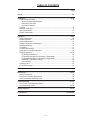
TABLE OF CONTENTS
Page
Safety
.....................................................................................................................2-6
Installation................................................................................................................8-12
Technical Specifications ............................................................................................8
Input and Output Specifications
Cable and Fuse Sizes
Physical Dimensions
Location .....................................................................................................................9
Machine Grounding....................................................................................................9
Input Connections ....................................................................................................10
Output Connections .................................................................................................11
Operation................................................................................................................13-23
Safety Instructions ...................................................................................................13
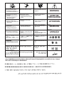
Graphic Symbols ................................................................................................14-15
General Description .................................................................................................16
Design Features and Advantages............................................................................16
Welding Capability ...................................................................................................17
Limitations................................................................................................................17
Controls and Settings...............................................................................................18
Hand and Foot Amptrol Operation ...........................................................................20
Welding Operation ..............................................................................................20-23
Tig Welding Guidelines .......................................................................................20
Tig Welding Sequence of Operation (2 Step Mode) ...........................................21
Tig Welding Sequence of Operation (4 Step Mode) ...........................................22
Advanced Tig Welding Features.........................................................................22
Stick Welding ......................................................................................................23
Auxillary Power ........................................................................................................23
Overload Protection .................................................................................................23
Accessories.................................................................................................................24
Maintenance ...........................................................................................................25-26
Safety Precautions...................................................................................................25
Routine and Periodic Maintenance ..........................................................................25
General Assembly Exploded View...........................................................................26
Troubleshooting ....................................................................................................27-34
How To Use Troubleshooting Guide........................................................................27
Troubleshooting Guide .......................................................................................28-34
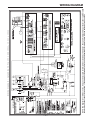
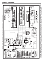
Wiring Diagrams ....................................................................................................35-36
Parts Manual .................................................................................................APPENDIX
–7–
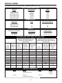
INSTALLATION
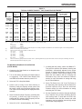
TECHNICAL SPECIFICATIONS - SQUARE WAVE TIG 255
INPUT - SINGLE PHASE ONLY
Standard
Voltage
208/230/460/1/60
230/460/575/1/60
200/240/400/1/50/60
220/380/440/1/50/60
380/415/500/1/50/60
220/380/415/1/50/60
Code
Number
10022
10023
10024
10452
10453
10451
Input Current at
Rated Output (1)
81/74/37
74/37/30
85/77/44
77/45/39
45/41/33
77/45/41
RATED OUTPUT
Duty Cycle
40% Duty Cycle
NEMA Class II (40)
60% Duty Cycle
100% Duty Cycle
Amps
255
Volts at Rated Amperes
30
200
150
28
26
OUTPUT
Welding Current Range
(Continuous)
5-315 Amps
AC and DC
Auxiliary Power
115 Volts AC, 10 Amps
Constant Open
Circuit Voltage
Stick OCV: 76
TIG OCV: 53
220Volts AC, 2 Amps
(50/60 Hz. machines only)
RECOMMENDED INPUT WIRE AND FUSE SIZES
For all Stick, DC TIG, and Balanced AC TIG
Welding at 255A/30V/40% Duty Cycle
Based on the 1993 US. National
Electrical Code
For Unbalanced AC TIG Welding Above 180
Amps, 255A/16V/40% Duty Cycle, Auto
Balance Based on the 1993 U.S. National
Electrical Code
Input
Amperes
Type 75°C
Copper Wire in
Conduit AWG
(IEC) Sizes
Type 75°C
Copper Ground
Wire in Conduit
AWG (IEC)
Sizes
6 (16mm2)
102
4 (25mm2)
6 (16mm2)
6 (16mm2)
8 (10mm2)
92
4 (25mm2)
6 (16mm2)
10 (6mm2)
46
8 (10mm2)
10 (6mm2)
Input
Voltage /
Frequency
Fuse
(Super Lag)
or Breaker
Size
Input
Ampere
Rating on
Nameplate
Type 75°C
Copper Wire in
Conduit AWG
(IEC) Sizes
Type 75°C
Copper Ground
Wire in Conduit
AWG (IEC)
Sizes
208/60
125
81
6 (16mm2)
230/60
100
74
460/60
50
37
10 (6mm2)
575/60
50
30
10 (6mm2)
10 (6mm2)
37
10 (6mm2)
10 (6mm2)
200/50/60
125
85
6 (16mm2)
6 (16mm2)
105
4 (25mm2)
6 (16mm2)
220/50/60
100
77
6 (16mm2)
8 (10mm2)
96
4 (25mm2)
8 (10mm2)
8 (10mm2)
55
8 (10mm2)
8 (10mm2)
380/50/60
70
46
8 (10mm2)
400/50/60
60
43
10 (6mm2)
10 (6mm2)
53
8 (10mm2)
10 (6mm2)
415/50/60
60
41
10 (6mm2)
10 (6mm2)
51
8 (10mm2)
10 (6mm2)
440/50/60
60
39
10 (6mm2)
10 (6mm2)
48
8 (10mm2)
10 (6mm2)
34
10 (6mm2)
10 (6mm2)
42
10 (6mm2)
10 (6mm2)
500/50/60
50
PHYSICAL DIMENSIONS
Height
30.5 in.
775 mm
Width
19.0 in.
(Lift bail, add 3.5 in)
Depth
30.0 in.
485 mm
(Lift bail, add 90 mm)
760 mm
300 lbs
(137 kg)
(1) Unbalanced TIG welding above 180 amps will draw higher input currents; see Supply Connections section.
–8–
Weight
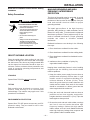
INSTALLATION
Read entire installation section before starting
installation.
MACHINE GROUNDING AND HIGH
FREQUENCY INTERFERENCE
PROTECTION
Safety Precautions
The frame of the welder must be grounded. A ground
terminal marked with the symbol
is located at
the bottom of the input box for this purpose. See your
local and national electrical codes for proper
grounding methods.
WARNING
ELECTRIC SHOCK can kill.
• Only qualified personnel should
perform this installation.
The spark gap oscillator in the high frequency
generator, being similar to a radio transmitter, can be
blamed for many radio, TV and electronic equipment
interference problems. These problems may be the
result of radiated interference. Proper grounding
methods can reduce or eliminate radiated
interference.
• Turn the input power OFF at the
disconnect switch or fuse box
before working on this
equipment.
• Do not touch electrically hot
parts.
• Always connect the Square Wave
TIG 255 grounding terminal
(located on the bottom of the
input connection box) to a good
electrical earth ground.
Radiated interference can develop in the following
four ways:
1. Direct interference radiated from the welder.
2. Direct interference radiated from the welding leads.
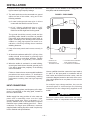
SELECT SUITABLE LOCATION
3. Direct interference radiated from feedback into the
power lines.
Place the welder where clean cooling air can freely
circulate in through the rear louvers and out through
the side louvers. Dirt, dust or any foreign material that
can be drawn into the welder should be kept at a
minimum. Failure to observe these precautions can
result in excessive operating temperatures and
nuisance shut-downs.
4. Interference from re-radiation of “pickup” by
ungrounded metallic objects.
Keeping these contributing factors in mind, installing
equipment per the following instructions should
minimize problems.
1. Keep the welder power supply lines as short as
possible and completely enclose them in rigid
metallic conduit or equivalent shielding for a
minimum distance of 50 feet (15.2m). There
should be good electrical contact between this
conduit and the welder. Both ends of the conduit
should be connected to a driven ground and the
entire length should be continuous.
STACKING
Square Wave TIG 255’s cannot be stacked.
TILTING
Each machine must be placed on a secure, level
surface, either directly or on a recommended
undercarriage. The machine may topple over if this
procedure is not followed.
2. Keep the work and electrode leads as short as
possible and as close together as possible.
Lengths should not exceed 25 ft (7.6m). Tape the
leads together when practical.
ENVIRONMENTAL PROTECTION
3. Be sure the torch and work cable rubber coverings
are free of cuts and cracks that allow high
frequency leakage. Cables with high natural
rubber content, such as Lincoln Stable-Arc® better
resist high frequency leakage than neoprene and
other synthetic rubber insulated cables.
Square Wave TIG 255 power sources carry an IP21
protection rating. They are rated for use in rainsheltered environments.
–9–
INSTALLATION
4. Keep the torch in good repair and all connections
tight to reduce high frequency leakage.
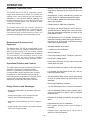
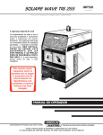
See Figure 1 for the location of the rating plate, the
entry hole, and the reconnect panel.
FIGURE 1 - REAR PANEL
5. The work terminal must be connected to a ground
within ten feet of the welder, using one of the
following methods:
a) A metal underground water pipe in direct
contact with the earth for ten feet or more.
1
2
b) A 3/4” (19mm) galvanized pipe or a 5/8”
(16mm) solid galvanized iron, steel or copper
rod driven at least eight feet into the ground.
The ground should be securely made and the
grounding cable should be as short as possible
using cable of the same size as the work cable, or
larger. Grounding to the building frame electrical
conduit or a long pipe system can result in reradiation, effectively making these members
radiating antennas.
3
6. Keep all access panels and covers securely in
place.
4
7. All electrical conductors within 50 ft (15.2m) of the
welder should be enclosed in grounded rigid
metallic conduit or equivalent shielding. Flexible
metallic conduit is generally not suitable.
1. RATING PLATE
2. INPUT ENTRY &
RECONNECT PANEL
8. When the welder is enclosed in a metal building,
several good earth driven electrical grounds (as in
5 (b) above) around the periphery of the building
are recommended.
Failure to observe these recommended installation
procedures can cause radio or TV interference
problems and result in unsatisfactory welding
performance resulting from lost high frequency
power.
INPUT CONNECTIONS
Be sure the voltage, phase, and frequency of the input
power is as specified on the rating plate, located on
the rear of the machine.
Welder supply line entry provision is in the case rear
panel with a removable cover over the input
connection panel area. Entry is through a 1.7 in
(43mm) diameter hole in the case back. European
machines have a plastic bushing good for 3 - 10mm2
conductors. For larger input conductors a customer
supplied plastic bushing should be used if required by
local or national code specifications.
3. 220V RECEPTACLE & BREAKER
(50/60 HZ MACHINE ONLY)
4. 115V RECEPTACLE & BREAKER
Have a qualified electrician connect the input leads to
L1 and L2 of the input panel in accordance with all
local codes and national electrical codes, and the
connection diagram located on the inside of the cover.
Use a single phase line or one phase of a two or three
phase line.
On multiple input voltage welders, be sure the
reconnect panel is connected per the following
instructions for the voltage being supplied to the
welder.
CAUTION
Failure to follow these instructions can cause
immediate failure of components within the welder.
___________________________________________
– 10 –
INSTALLATION
Welders are shipped connected for the highest input
voltage as listed on the rating Plate. To change this
connection for a different input voltage, reconnect the
power strap (P) to the terminal corresponding to the
input voltage used. Designations on reconnect panel,
LOW, MID and HIGH correspond to the nameplate
input voltages of a triple voltage welder. Dual voltage
welders use only LOW and HIGH. Single voltage
welders use only HIGH.
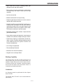
FIGURE 2 - FRONT PANEL
1
4
2
3
L9119-1
DC
I
EXAMPLE: On a 208/230/460 volt welder, LOW is
208V, MID is 230V, and HIGH is 460V.
POWER
AC
DO NOT SWITCH
WHILE WELDING
O
DC
Fuse the input circuit with the recommended super lag
fuses or delay type1 circuit breakers. Choose an input
and grounding wire size according to local or national
codes, refer to Specification page at the beginning of
this chapter. Using fuses or circuit breakers
smaller than recommended may result in “nuisance”
shut-offs from welder inrush currents even if not
welding at high currents.
WATER
OUT
WORK
IN
GAS
OUT
WARNING
L9119-2
ELECTRODE
REMOTE
IN
7
5
Unbalanced AC TIG welding draws higher input
currents than those for stick, DC TIG, or Balanced AC
TIG welding. The welder is designed for these higher
input currents. However, where unbalanced AC TIG
welding above 180 amps is planned, the higher input
currents require larger input wire sizes and fuses.
Refer to Specification page at the beginning of this
chapter.
The Square Wave TIG 255 should be permanently
wired into the power system. No plugs or connectors
are necessary.
OUTPUT CONNECTIONS
WARNING
1. CONTROL AND DISPLAY AREA
2. POWER SWITCH
3. THERMOSTATIC
PROTECTION LIGHT
4. POLARITY SWITCH
TIG welding torches come with 12.5 ft (3.8m) and 25 ft
(7.6m) cables. Use the shorter length whenever
possible to minimize possible radio interference
problems. With power source off, connect the torch
cable to the “Electrode” stud on the welder. Connect
a separate work cable to the “Work” stud of the
welder. See Table 1 for recommended work cable
sizes. Both work and electrode cables should be
routed through the cable strain relief holes provided in
the base directly below the welding output terminals.
TABLE 1
Cable Sizes for Combined Lengths of Copper
Electrode and Work Cable
See Figure 2 for the location of the work and
electrode terminals, the gas and optional water
solenoids, and the Remote Receptacle.
called
“inverse
time”
or
“thermal/magnetic”
circuit breakers; circuit breakers which have a delay
in
tripping
action
that
decreases
as
the
magnitude
of the current increases.
5. OPTIONAL WATER SOLENOID
6. GAS SOLENOID
7. WORK (LEFT) AND
ELECTRODE STUDS
8. REMOTE RECEPTACLE
TIG TORCH CONNECTION
To avoid receiving a high frequency shock, keep the
TIG torch and cables in good condition.
___________________________________________
1 Also
8
6
Machine Size
Lengths up to
100 ft
100 to 200 ft
200 to 250 ft
255 Amp
40% Duty Cycle
#2 (35mm2)
#1 (45mm2)
1/0 (55mm2)
TIG torches include the necessary gas and, when
designed for water cooling, water hoses. Connect the
fittings on these hoses to the welder fittings. Any torch
conforming to Compressed Gas Association (CGA)
standards can be connected.
– 11 –
INSTALLATION
The welder fittings have the following threads: Gas
Inlet and Outlet: 5/8”-18 right-hand female; Water inlet
and Outlet: 5/8”-18 left-hand female. The cylinder of
inert shielding gas must be equipped with a pressure
regulator and flow meter. Install a hose between the
flow meter and gas inlet on the welder.
WARNING
Observe the safety precautions necessary for
handling and using compressed gas containers.
Contact your supplier for specific information.
___________________________________________
DO NOT operate a water-cooled torch unless water is
flowing. Water doesn’t flow until solenoid is actuated.
If using a water-cooled torch with a Magnum water
cooler, connect the cooler water outlet to the ‘Water
Valve In” fitting. Connect the TIG torch inlet to the
“Water Valve Out” fitting.
If using a water-cooled torch with a free-running water
supply, install a water line between the welder “Water
Inlet” and the supply. Include a strainer in the water
supply line to prevent dirt particles from obstructing
water flow in the valve and cooling chamber of the
TIG torch. Failure to do so could result in water valve
malfunction and overheating of the water-cooled
torch. Connect the torch water line to the welder
“Water Out” fitting. Use a nonmetallic drain line from
the electrode connection to the drain or water
recirculating pump.
For other conditions, consult the manufacturer’s
instructions for the water cooler or TIG torch being
used.
STICK ELECTRODE CABLE CONNECTION
Turn the Power switch Off. Run the electrode and
work cables through the strain relief holes below the
welding output terminals, and connect the cables to
the proper terminals. This strain relief prevents
damage to the welding output terminals if the cables
are pulled excessively. Select cable size according to
Table 1.
WARNING
Do not connect a TIG torch and stick electrode cable
at the same time. They will both be electrically HOT
whenever the output contactor is energized.
___________________________________________
– 12 –
OPERATION
OPERATING INSTRUCTIONS
General Warnings
SAFETY INSTRUCTIONS
WARNING
ELECTRIC SHOCK
can kill.
• Do not touch electrically live parts
or electrode with skin or wet
clothing.
• Insulate yourself from work and
ground.
• Always wear dry insulating
gloves.
FUMES AND GASES
can be dangerous.
• Keep your head out of fumes.
• Use ventilation or exhaust to
remove fumes from breathing
zone.
WELDING SPARKS
can cause fire or
explosion
• Keep flammable material away.
• Do not weld on containers that
have held combustibles.
ARC RAYS
can burn.
• Wear eye, ear and body
protection.
Observe additional Safety Guidelines detailed in
the beginning of this manual.
– 13 –
OPERATION
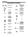
GRAPHIC SYMBOLS THAT APPEAR ON
THIS MACHINE OR IN THIS MANUAL
&
TIG 2-STEP
2
TIG 4-STEP
AFTERFLOW /
AFTERFLOW
TIME
CONTINUOUS
HIGH
FREQUENCY
STICK
CURRENT
CONTROL
OUTPUT
START ONLY
HIGH
FREQUENCY
LOCAL
CURRENT
CONTROL
OFF
ON
REMOTE
CURRENT
CONTROL
&
CLEAN
(INCREASE
POSITIVE
POLARITY)
&
PENETRATE
(INCREASE
NEGATIVE
POLARITY)
INCREASE
A
OUTPUT
DECREASE
TIG PULSER
HF
HIGH
FREQUENCY
– 14 –
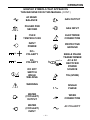
OPERATION
GRAPHIC SYMBOLS THAT APPEAR ON
THIS MACHINE OR IN THIS MANUAL (CONT.)
f
AC WAVE
BALANCE
GAS OUTPUT
PULSED PER
SECOND
GAS INPUT
OVER
TEMPERATURE
ELECTRODE
CONNECTION
INPUT
POWER
&
DC+
POLARITY
&
DCPOLARITY
PROTECTIVE
GROUND
SINGLE PHASE
TRANSFORMER
AC & DC
RECTIFIER
POWER
SOURCE
DO NOT
SWITCH
WHILE
WELDING
TIG (GTAW)
WARNING
SINGLE
PHASE
WATER
(COOLANT)
OUTPUT
WORK
CONNECTION
WATER
(COOLANT)
INPUT
AC POLARITY
– 15 –
OPERATION
GENERAL DESCRIPTION
The Square Wave TIG 255 is a constant current,
single range square wave AC/DC TIG (GTAW) arc
welding power source with built-in high frequency
stabilization. It also has stick (SMAW) capability. It is
available from the factory in one model only; there are
no factory installed options, only variations in input
voltage and frequency.
The Square Wave TIG 255 includes advanced
features such as Auto-Balance™, 2-Step/4-Step Arc
Start Switch operation and a TIG pulser. In addition,
fixed preflow and variable afterflow timers are
included for shielding gas and cooling water control.
• Welding current limit can be preset from 5 to 315
amps and is displayed on the Ammeter when not
welding.
• Auto Balance circuitry automatically provides the
proper amount of cleaning and penetration when
AC TIG welding. Manual AC wave balance adjustment is also possible.
• 2-Step/4-Step Arc Start Switch Capability.
• TIG Pulser with On/Off Selection, and Pulses Per
Second adjustment. Background current and duty
cycle are automatically adjusted according to the
peak welding current.
• Fixed preflow time of 0.5 seconds. Preflow time is
eliminated if welding restarts during gas afterflow of
previous weld. This avoids unnecessary delays
when making repeated welds.
Recommended Processes And
Equipment
• Adjustable afterflow time control.
The Square Wave TIG 255 is recommended for the
TIG (GTAW) and stick (SMAW) welding processes
within its output capacity of 5 to 315 amps, on both
AC and DC polarity. It is compatible with all Magnum
TIG accessories (see Accessory section in this
manual), as well as many industry standard
items, such as TIG torches, hoses, and water coolers.
Operational Features and Controls
The Square Wave 255 has the following controls as
standard: TIG 2-Step/TlG 4-Step/Stick mode
selection, Local/Remote current control selection,
Continuous/Start Only/Off high frequency selection,
Auto/Manual AC wave balance selection with the
manual wave balance adjustment, TIG pulser On/Off
selection with frequency adjustment, afterflow
adjustment, and DC+/DC-/AC polarity selection.
• Local/Remote current selection.
• Stick/TlG selection.
• Continuous/Start/Off High Frequency selection.
• DC+/AC/DC- Polarity Switch.
• Power Factor Correction for lower input currents and
smaller input wire sizes.
• Remote Receptacle for Amptrol or Arc Start Switch.
• Low Voltage Arc Start Switch Circuit (24 V AC) for
maximum operator safety.
• Gas and optional Water Valves: Inlet & outlet fittings
conform to Compressed Gas Association (CGA)
standards.
• Built-in High Frequency Generator.
Design Features and Advantages
• 115 Volt Receptacle with 10 amp Circuit Breaker.
• Designed to NEMA EW-1 & International IEC-974
Standards.
• 220 Volt European (Schuko) type receptacle with 2
amp circuit breaker for water coolers (50/60Hz
machines only).
• Single output range of 5-315 amps covers the
majority of all TIG welding applications.
• Excellent arc starting and stability up through 315
amps.
• Solid State Output Contactor: no noise, no parts to
wear.
• High resistance to AC arc rectification.
• Digital Ammeter and Voltmeter for precise readings
from 5 to 315 amps welding.
• No tungsten spitting within current range of
electrode.
• Compact size, requires only a 19 in x 30 in
(485 mm x 760 mm) footprint.
– 16 –
OPERATION
• Strain relief holes in base for welding cables, gas
and water hoses and control cables.
• Easy access for input connections. Connections
are simple strip and clamp of input wires (no lugs
required).
• Low fan noise at idle.
• Modular construction for easy servicing.
• Simple keypad layout allows even novice users to
operate with minimal instruction.
• Unused controls are automatically locked out to
simplify setup. Examples: the AC wave balance
control has no effect in DC; the High Frequency and
gas and water valves do not operate in Stick mode;
TIG Pulser is locked out in the Stick mode.
• Recessed panels protect controls, output terminals
gas and water fittings.
• Large safety margins and protective circuits protect
rectifiers from transient voltages and high currents.
• Submersion dipping of assembled transformer,
choke, rectifier in special sealing/insulating material
gives added protection against moisture and
corrosive atmospheres.
• Line Voltage Compensated.
• Thermostatically Protected.
• Electronic Over Current Protection.
• Hinged Cover over Output Panel.
Welding Capability
The Square Wave TIG 255 is rated at 255 amps, 30
volts, at 40% duty cycle on a ten minute basis. It is
capable of higher duty cycles at lower output currents.
If the duty cycle(s) are exceeded, a thermal protector
will shut off the output until the machine cools to a
reasonable operating temperature.
Limitations
Arc Gouging cannot be performed with the Square
Wave TIG 255.
The Square Wave TIG 255 is not recommended for
pipe thawing.
– 17 –
OPERATION
CONTROLS AND SETTINGS
All operator controls and adjustments are located on the case front of the Square Wave TIG 255. Refer to Figures
3 and 4 and corresponding explanations.
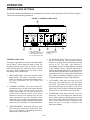
FIGURE 3 - CONTROL PANEL KEYS
7
G2612
THE LINCOLN ELECTRIC COMPANY
CLEVELAND, OHIO
AC/DC OUTPUT CAPACITY:
USA
CURRENT CONTROL
WELD MODE
LOCAL
TIG 2-STEP
HF HIGH FREQUENCY
REMOTE
AC WAVE BALANCE
30 VOLTS
40% DUTY CYCLE
TIG PULSER
2
AFTERFLOW
CONTINUOUS
OFF
HF
AMPS
TIG 4-STEP
255 AMPS
AUTO-
MANUAL
BALANCE
BALANCE
START ONLY
SECONDS
ON
PULSES PER SECOND
CLEAN
HF
2
f
STICK
A
PENETRATE
OFF
LINCOLN
R
ELECTRIC
2
1
1.
2.
3.
4.
6
4
5
3
WELD MODE KEYS
CURRENT CONTROL KEYS
HIGH FREQUENCY KEYS
AC WAVE BALANCE KEYS
CONTROL PANEL KEYS
The keys are grouped into six areas, described below
and in Figure 3. Some areas are active in both TIG
and Stick, while others are active in TIG only. The red
LED indicator lights are used to tell which functions
are active, and the display (Item 1) is used to check
the settings of the up/down keys.
1. WELD MODE KEYS: These keys select the Weld
Mode desired: TIG 2-Step, TIG 4-Step, or Stick.
Read the complete Operating Instructions section
for more information on TIG 2-Step and
TIG 4-Step.
2. CURRENT CONTROL: This area contains the
Local/Remote keys, as well as the Amps Up/Amps
Down keys. These keys are used to set the
welding current from 5 to 315 amps, as well as to
select Local or Remote control. Local control
allows the current to be adjusted only with the
Amps Up/Amps Down keys. Remote control
allows the use of a hand or foot operated remote
control. Read the complete Operating Instructions
section for more information on Local and Remote.
5. TIG PULSER KEYS
6. AFTERFLOW KEYS
7. DISPLAY
4. AC WAVE BALANCE: These keys are active in
the AC TIG mode only. They are used to set the
amount of cleaning and/or penetration produced
during an AC TIG weld. Auto Balance™
automatically sets the AC Wave Balance according
to the welding current. If manual adjustment is
desired, the Manual Balance key can be pressed,
and the balance adjusted from +5 (cleaning) to -10
(penetration) with the Cleaning and Penetration
keys. Read the Advanced Features section for a
complete explanation of the AC Wave Balance.
5. TIG PULSER: These keys are active in the TIG
mode only. The On/Off keys turn the TIG Pulser
on and off. The Pulses Per Second keys adjust
the pulsing frequency up and down, from 0.5 to 10
pulses per second. Read the Advanced Features
section for more information on the TIG Pulser.
6. AFTERFLOW: These keys are active in the TIG
mode only. They must adjust the afterflow time
from 5 to 50 seconds for shielding gas and cooling
water flow through solenoids located on the case
front. As the Afterflow time is adjusted, the
Afterflow time, in seconds, is shown in the
Momentary Display.
3. HIGH FREQUENCY: These keys are active in the
TIG mode only. Select from Continuous, Start
Only, or Off. Read the TIG Welding Section for
information on High Frequency.
– 18 –
OPERATION
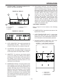
7. CONTROL PANEL: The display is divided into five
sections. See Figures 4A and 4B.
E. BAR GRAPH DISPLAY: This area provides a
graphical display of values shown on the Ammeter
and on the Momentary Display. When the
Momentary Display is blank (as in Figure 4A), the
Bar Graph Display represents values shown on the
ammeter. When a low value is shown on the
ammeter, only a few “bars” will appear on the left
hand side of the Bar Graph Display. As the
ammeter value increases, more and more “bars”
will appear. Whenever a value increases, more
and more “bars” will appear. Whenever a value
appears in the Momentary Display, the Bar Graph
Display will represent the Momentary Display
value, not the ammeter value.
FIGURE 4A - DISPLAY
C
D
B
A
CASE FRONT CONTROLS
E
A. AC/DC INDICATOR
B. VOLTMETER
C. AMMETER
Refer to Figure 5 for the location of the following
controls:
D. MOMENTARY DISPLAY
E. BAR GRAPH
1. POWER SWITCH: Controls the input power to the
Square Wave TIG 255.
FIGURE 4B - DISPLAY
2. OVER TEMPERATURE LIGHT: A yellow light
which only lights when an over temperature
situation occurs. See the Maintenance Section for
more information on the thermostatic protection.
3. POLARITY SWITCH: Selects DC+, AC or DCwelding polarity. Do not switch under load.
A. AC/DC INDICATOR: This symbol represents the
output polarity of the 255 . . . either AC or DC. AC
is shown in Figure 4A; DC is shown in Figure 4B.
B. VOLTMETER: This meter displays open circuit
voltage as well as welding voltage, as measured
on the output studs of the Square Wave TIG 255.
FIGURE 5 - CASE FRONT CONTROLS
3
1
2
L9119-1
DC
– 19 –
POWER
AC
DO NOT SWITCH
WHILE WELDING
O
D. MOMENTARY DISPLAY: This area is blank under
most conditions; see Figure 4A. Different values
may be displayed here as certain keypad keys are
pressed. See Figure 4B; the TIG Pulser is being
adjusted, so the Pulse Frequency, 2.0 Hz, is being
displayed. Information in the Momentary Display
lasts for five seconds after a key is pressed. Read
the complete Operating Instructions section for
more information on the values that appear in the
Momentary Display.
I
C. AMMETER: The ammeter can display preset
current (for setting the welding current before
welding) and actual welding current (the value of
the welding current during a weld). Read the
complete Operating Instructions section for more
information on the ammeter.
DC
WATER
OUT
IN
WORK
1.
2.
3.
GAS
OUT
WARNING
ELECTRODE
IN
POWER SWITCH
THERMOSTATIC
PROTECTION LIGHT
POLARITY SWITCH
L9119-2
REMOTE
OPERATION
WELDING OPERATION
HAND AND FOOT AMPTROL ACCESSORY
OPERATION
TIG Welding
Both the Hand and Foot Amptrol work in a similar
manner. They are meant to be used for remote current
control when Remote Current Control is selected.
The TIG 2-Step mode must be selected when using
an Amptrol for remote current control. As explained
below, Amptrols can also be used as arc start
switches if Local Current Control is selected.
For simplicity, the following explanation will refer only
to “Amptrols”, meaning both Foot and Hand models.
The term “minimum” refers to a Foot pedal in the “up”
position, as it would be with no foot pressure, or a
Hand Amptrol in the relaxed position, with no thumb
pressure. “Maximum” refers to a fully depressed Foot
Amptrol, or a fully extended Hand Amptrol.
The Amptrol is capable of controlling the output
current from 5 amps to the preset current displayed on
the ammeter. For example, if the ammeter is preset
for 200 amps and the Current Control switch is in the
REMOTE position, the Amptrol, when depressed just
past its minimum position, will cause the Square
Wave TIG 255 to weld at 5 amps. At the Amptrols
maximum position, the output would be near 200
amps.
Familiarize yourself with the Controls and Display
Section before attempting operation of the Square
Wave TIG 255.
TIG Welding Guidelines
TIG welding can be done in either the TIG 2-Step or
the TIG 4-Step Weld Mode. TIG 2-Step is typically
used with Hand or Foot Amptrols, with Remote
Current control. TIG 4-Step is typically used with Arc
Start switches and Local Current Control, because it
provides a very brief current upslope, and a 5-second
current downslope. TIG 4-Step also functions like a
trigger interlock, making it unnecessary to hold down
the Arc Start switch during a weld. Note, on later
versions, TIG 4-Step was made available for use with
Remote Current Control with the release of ROM
version S21228-4 (initiated on Control board G2150-3
on codes 10022 and higher). This feature requires
that the remote control devise in use must have
separate Arc Start and Output Control mechanisms.
Read the TIG Welding Sequence of Operation
sections for more details on 2-Step and 4-Step
Operation.
It is important to note that, for many applications, the
tungsten will not start an arc at only 5 amps. To start
an arc reliably, it is important to depress the Amptrol
far enough so that the machine output current is near
the tungsten operating range. In the example above, a
3/32” tungsten may be used on DC- to weld near 200
amps. To start the weld, the operator may have to
depress the Amptrol approximately 1/4 of the way
down, or to nearly 50 amps, in order to start the arc.
Merely depressing the Amptrol to its 5 amp minimum
position will not start the arc.
If the Current Control switch is set to the LOCAL
position, an Amptrol can be used as an arc start
switch. Depressing the Amptrol just past minimum will
cause the Amptrols built-in arc start switch to close,
and backing off completely causes the built-in start
switch to open. The Amptrol will have no effect on the
welding current when used as an arc start switch.
– 20 –
TABLE 2
RECOMMENDED POLARITY
SETTINGS FOR TIG WELDING
Type of Welding
Electrode
Polarity
High Frequency
Setting
Stainless Steel
DC-
START
Aluminum & Magnesium
AC
CONTINUOUS
Other Metals
DC-
START
OPERATION
TABLE
3
(1)
(2)
TYPICAL CURRENT RANGES FOR TUNGSTEN ELECTRODES
AC
DCEN ( - )
DCEP ( + )
Tungsten
Electrode
Diameter
in. (mm)
1%, 2%
Thoriated
Tungsten
1%, 2%
Thoriated
Tungsten
.010 (.25)
0.020 (.50)
0.040 (1.0)
2-15
5-20
15-80
(3)
1/16
(1.6)
70-150
3/32
1/8
(2.4)
(3.2)
5/32
3/16
1/4
(4.0)
(4.8)
(6.4)
(1)
(2)
(3)
(4)
(5)
Unbalanced Wave
Balanced Wave
Approximate Argon
Gas Flow Rate
C.F.H. (1/min.)
Pure
Tungsten
1%, 2%
Thoriated
Tungsten
Zirconiated
Pure
Tungsten
1%, 2%
Thoriated
Tungsten
Zirconiated
2-15
5-15
10-60
2-15
5-20
15-80
2-15
10-20
20-30
--5-20
20-60
3-8
5-10
5-10
(2-4) 3-8
(3-5) 5-10
(3-5) 5-10
(2-4)
(3-5)
(3-5)
#4, #5, #6
10-20
50-100
70-150
30-80
60-120
5-10
(3-5) 9-13
(4-6)
#5, #6
150-250
250-400
15-30
25-40
100-160
150-210
140-235
225-325
60-130
100-180
100-180
160-250
15-23 (7-11) 11-15 (5-7)
400-500
500-750
750-1000
40-55
55-80
80-125
200-275
250-350
325-450
300-400
400-500
500-630
100-240
190-300
250-400
200-320
290-390
340-525
21-25 (10-12) 13-17 (6-8)
23-27 (11-13) 18-22 (8-10)
28-32 (13-15) 23-27(11-13)
(3)
(3)
Aluminum
Stainless
Steel
13-17 (6-8) 11-15 (5-7)
TIG Torch
Nozzle
Size (4), (5)
#6, #7, #8
#8, #10
When used with argon gas. The current ranges shown must be reduced when using argon/helium or pure helium shielding gasses.
Tungsten electrodes are classified as follows by the American Welding Society (AWS):
Pure . . . . . . . . . . . . . . . EWP
1% Thoriated . . . . . . . . EWTh-1
2% Thoriated . . . . . . . . EWTh-2
Though not yet recognized by the AWS, Ceriated Tungsten is now widely accepted as a substitute for 2% Thoriated Tungsten in AC and DC applications.
DCEP is not commonly used in these sizes.
TIG torch nozzle “sizes” are in multiples of 1/16ths of an inch:
#4 = 1/4 in.
(6 mm)
#5 = 5/16 in.
(8 mm)
#6 = 3/8 in.
(10 mm)
#7 = 7/16 in.
(11 mm)
#8 = 1/2 in.
(12.5 mm)
#10 = 5/8 in.
(16 mm)
TIG torch nozzles are typically made from alumina ceramic. Special applications may require lava nozzles, which are less prone to breakage, but cannot
withstand high temperatures and high duty cycles.
TIG WELDING SEQUENCE OF OPERATION
(2-STEP MODE)
1. Connect an Arc Start Switch or an Amptrol to the
Remote Receptacle.
2. Turn on the welder, gas supply and water supply (if
so equipped). The Control Panel Display and
red LEDS will illuminate when the power is on.
7. If welding with AC polarity, select Auto Balance™.
This gives the optimum ratio between cleaning and
penetration, automatically adjusted for the output
current. If manual adjustment of the AC Wave
Balance is desired, select Manual Balance, and
adjust the wave balance with the Cleaning and
Penetration keys. See the Advanced Features
section for more information on setting and using
the AC Wave Balance.
3. Select the TIG 2-Step Weld Mode.
4. Select Local (if using an Arc Start Switch) or
Remote (if using an Amptrol) current control. Set
the output current using the Amps Up/Down keys.
The output current setting will be displayed on the
Ammeter.
5. Select Continuous High Frequency if welding with
AC polarity, or Start Only High Frequency if
welding with DC- polarity. High Frequency Off can
be used for scratch start welding.
8. Select TIG Pulser On or Off. If the TIG Pulser is
on, adjust the pulse frequency with the Pulses Per
Second Up/Down keys. See the Advanced
Features section for more information on setting
and using the TIG Pulser.
9. Set the Afterflow time with the Seconds Up/Down
keys. Afterflow time provides shielding gas flow
(and cooling water, if used) after the weld. Use
short Afterflow times with low currents and small
tungstens, use long afterflow times at high output
currents with large tungstens.
6. Select AC or DC- electrode polarity. See Table 2.
– 21 –
OPERATION
10. Press and release the Arc Start Switch, and set
the gas flow meter. The welder is now ready for
welding.
11. Position the tungsten electrode at the start of the
weld at a 65 to 75 angle with the horizontal so
that the electrode is approximately 1/8” (4mm)
above the work piece. Press the Arc Start Switch.
This opens the gas and water valves to
automatically purge air from the hose and torch.
After a 0.5 second preflow time, the high
frequency becomes available to strike the arc.
12. Hold the Arc Start Switch or Amptrol down until an
arc is established. If using an Amptrol, read the
section on Hand and Foot Amptrol Operation.
Release the Arc Start Switch or Amptrol to stop
the arc and start the Afterflow timer. After the
Afterflow time has expired, the gas and water
valves will close. To make another weld, repeat
steps 11 and 12.
TIG WELDING SEQUENCE OF OPERATION
(4-Step Mode)
1.
Connect an Arc Start Switch to the Remote
Receptacle.
2.
Turn the welder, gas supply and water supply (if so
equipped), on. The Control Panel Display and red
LEDS will illuminate when the power is on.
3.
Select the TIG 4-Step Weld Mode.
4.
Select the Local current control. Set the output
current using the Amps Up/Down keys. The output
current setting will be displayed on the Ammeter. On later
version machines, remote control is also available in TIG 4Step mode on codes 10022 and higher utilizing ROM
version S21228-4 and higher provided that the remote
control used has separate Arc Start and Output Control
mechanisms.
5.
Select Continuous High Frequency if welding with
AC polarity, or Start Only High Frequency if
welding with DC- polarity. High Frequency Off can
be used for scratch start welding.
6.
Select AC or DC- electrode polarity. See Table 2.
7.
If welding with AC polarity, select Auto Balance™.
This gives the optimum ratio between cleaning and
penetration, automatically adjusted for the output
current. If manual adjustment of the AC Wave
Balance is desired, select Manual Balance, and
adjust the wave balance with the Cleaning and
Penetration keys. See the Advanced Features
section for more information on setting and using
the AC Wave Balance.
8.
Select TIG Pulser On or Off. If the TIG Pulser is on, adjust
the pulse frequency with the Pulses Per Second Up/Down
keys. See the Advanced Features section for more
information on setting and using the TIG Pulser.
9. Set the Afterflow time with the Seconds Up/Down
keys. Afterflow time provides shielding gas flow
(and cooling water, if used) after the weld. Use
short Afterflow times with low currents and small
tungstens, long afterflow times at high output
currents with large tungstens.
10. Press and release the Arc Start Switch, and set
the gas flow meter. The welder is now ready for
welding.
11. Position the tungsten electrode at the start of the
weld at a 65 to 75 angle with the horizontal so
that the electrode is approximately 1/8” (4mm)
above the work piece. Press the Arc Start Switch.
This opens the gas and water valves to
automatically purge air from the hose and torch.
After a 0.5 second preflow time, the high
frequency becomes available to strike the arc.
12. Hold the Arc Start Switch down until an arc is
established. The arc will start at a low current
value. Release the Arc Start Switch. At this point,
the Square Wave TIG 255 will quickly ramp up to
the welding current, and the weld will continue
indefinitely. Press the Arc Start Switch a second
time to initiate a 5-second downslope. The current
will go down to a crater fill current that is equal to
25% of the welding current. Release the Arc Start
Switch to stop the arc and start the Afterflow timer.
After the Afterflow time has expired, the gas and
water valves will close. To make another weld,
repeat steps 11 and 12.
ADVANCED TIG WELDING FEATURES
AC Wave Balance and Auto Balance™
AC Wave Balance is a feature unique to square wave
TIG power sources. It is active only in AC TIG mode.
It controls the amount of positive and negative current
in the AC output.
The Square Wave TIG 255 allows the operator to
select Auto Balance™. This selection provides
automatic adjustment of the AC Wave Balance; it is
suitable for most welding conditions. Auto Balance
gives the ideal amount of cleaning and penetration,
based on the welding current output.
Manual adjustment of the AC Wave Balance is also
possible. Select the Manual Balance key, and the
Balance setting will appear in the Momentary Display.
Manual Balance settings vary from +5 (maximum
cleaning) to -10 (maximum penetration). A setting of
0 yields a balanced output (equal amounts of cleaning
and penetration). Use the following as a guide when
setting the Balance manually:
– 22 –
OPERATION
5. Clamp the electrode in the electrode holder, start
the weld by lightly touching the electrode to the
work. Stop the weld by pulling the electrode away
from the work piece. Note, in Stick Mode the
output studs remain electrically “HOT”.
BALANCED (0): The amounts of positive and
negative are the same.
CLEANING (+1 to +5): Provides more positive
current than negative. Since the positive
current produces the “cleaning” or oxide
removal on aluminum, this setting is used for
welding on heavily oxidized aluminum.
AUXILIARY POWER
PENETRATION (-1 to -10): Provides more negative
current than positive. The arc plasma will be
more concentrated and more easily directed
to where the heat is needed. Higher
penetration settings allow a given size of
tungsten to carry more current.
ALL MACHINES
The Square Wave TIG 255 provides 10 amps of 115
volt AC power at a standard NEMA 5-15R receptacle,
located on the lower case back of the machine. This
circuit is protected from shorts and overloading by a
10 amp circuit breaker, located next to the receptacle.
The auxiliary circuit is intended for running water
coolers and small power tools, whose current draw is
within the 10 amp rating. Note that some types of
equipment, especially pumps and large motors, have
starting currents which are significantly higher than
their running current. These higher starting currents
may cause the circuit breaker to open. If this situation
occurs, the user should refrain from using the Square
Wave TIG 255 auxiliary for that equipment.
CAUTION: Use only the amount of cleaning required
because the greater amount of positive current will
heat the tungsten more and possibly cause it to melt
or “spit”. Also, the arc is usually more flared and less
stable with more cleaning current.
In general, use just enough “cleaning” to remove
oxides and to give good wetting to the puddle.
TIG Pulser
The Square Wave TIG 255 contains a unique TIG
Pulser circuit. The TIG Pulser has On/Off selections,
as well as adjustments for Pulses Per Second
Up/Down. When the Pulser is turned On, or when the
Pulses Per Second are adjusted, the pulse frequency is
shown in the Momentary Display. It can be varied
from 0.5 Hz to 10 Hz in 0.5 Hz increments. (One
Hertz {Hz} is equivalent to one pulse per second.)
The background current (the welding current at the
low point of the pulse cycle) is automatically adjusted
from 40% to 60% of the peak current by the Square
Wave TIG 255. The duty cycle (the ratio between that
time spent at the peak current vs, the time spent at
the background current) is fixed at 50%.
50/60Hz MACHINES - (Codes 10024 thru 10026 & 10134)
Square Wave TIG 255 machines rated for 50/60Hz
operation provide 2 amps of 220 volt AC power at a
continental European (Schuko) type receptacle,
located on the lower case back of the machine. This
circuit is protected from shorts and overloading by a 2
amp circuit breaker, located above the receptacle.
The auxiliary circuit is intended for running water
coolers whose current draw is within the 2 amp rating
of the receptacle. Note that some types of equipment,
especially pumps and motors, have starting currents
which are significantly higher than their running
currents. These higher starting currents may cause
the circuit breaker to open. If this situation occurs, the
user should refrain from using the Square Wave TIG
255 auxiliary for that equipment.
STICK WELDING
1. Remove the amptrol or Arc Start Switch from the
Remote Receptacle.
2. Turn the welder on. The Control Panel Display
and red LEDS will illuminate when the power is on.
3. Select Stick Mode and Local Current Control. Set
the output current using the Amps Up/Down keys.
The output current setting will be displayed on the
Ammeter. No other functions or adjustments
operate in the Stick Mode.
4. Select DC+, AC or DC- electrode polarity.
OVERLOAD PROTECTION
This welder has thermostatic protection from
excessive duty cycles, overloads, loss of cooling, and
high ambient temperatures. When the welder is
subjected to an overload or loss of cooling, a
thermostat will open. This condition will be indicated
by the illumination of the yellow Thermostatic
Protection Light on the case front (see Figure 2).
Also, the Display will be blank, and all of the red
Control Panel LEDS will be out. The fan will continue
to run to cool the power source. No welding is
possible until the machine is allowed to cool and the
Thermostatic Protection Light goes out.
– 23 –
ACCESSORIES
OPTIONS / ACCESSORIES
• Hand Amptrol (K963)
• Foot Amptrol (K870)
• Arc Start Switch (K814)
• Magnum Cooler Horizontal TIG Mounting Bracket
(K559-2)
• Undercarriage (K932-1)
UNDERCARRIAGE FUNCTION
The Square Wave TIG 255 is designed to be used
with a Lincoln K932-1 Undercarriage. Complete
installation instructions are included with the K932-1
undercarriage. When the undercarriage is properly
installed, the Square Wave TIG 255 lift bail is nonfunctional. Do not attempt to lift the power source with
the undercarriage attached. The undercarriage is
designed for hand moving only; mechanized towing
can lead to injury and/or damage to the Square Wave
TIG 255.
INSTALLATION OF FIELD INSTALLED OPTIONS
Instructions for connecting the K932-1 Undercarriage
and the K559-2 Magnum Cooler Horizontal TIG
Mounting Bracket are included with those
accessories.
Installation of the K963 Hand Amptrol, the K814 Arc
Start Switch and K870 Foot Amptrol are as follows:
Lift the Output Cover Door (if so equipped) on the
Square Wave TIG 255. Feed the cable up through the
strain relief holes in the base, and connect the 6-pin
MS-type (Amphenol) connector to the Remote
Receptacle (See Figure 2). Secure with the threaded
collar.
– 24 –
MAINTENANCE
MAINTENANCE
Safety Precautions
WARNING
ELECTRIC SHOCK can kill.
• Only qualified personnel should
perform this maintenance.
• Turn the input power OFF at the
disconnect switch or fuse box
before working on this
equipment.
• Do not touch electrically hot
parts.
Routine and Periodic Maintenance
WARNING
To avoid receiving a high frequency shock, keep the
TIG torch and cables in good condition.
1. Disconnect power supply lines to machine before
performing periodic maintenance.
2. Periodically clean the inside of the machine with a
low pressure air system. Be sure to clean the
following components thoroughly. See Figure 6
for location of those components.
• Main Transformer
• Output Studs
• Polarity Switch
• Rectifier Assembly
• Control Box Assembly
• Spark Gap Assembly
• Protection PC Board - (Mounted to rear of control box assembly)
3. Inspect welder output and control cables for
fraying, cuts, and bare spots.
4. Keep TIG torch and cables in good condition.
5. The fan motor has sealed ball bearings which
require no maintenance.
6. Inspect spark gap spacing at regular intervals to
maintain a 0.015 in (0.4mm) gap. (Smallest
possible air gap consistent with good welding is
desirable to minimize R.F.I. problems.) Dressing
or any refinishing of the spark gap contacts is not
recommended. If the contact surfaces become
irregular or completely eroded, replacement of both
electrodes is recommended.
– 25 –
MAINTENANCE
FIGURE 6 - GENERAL ASSEMBLY EXPLODED VIEW
1
5
22
6
4
11
3
2
28
2
38
1.
2.
3.
4.
MAIN TRANSFORMER
OUTPUT STUDS
POLARITY SWITCH
RECTIFIER ASSEMBLY
5. CONTROL BOX ASSEMBLY
6. SPARK GAP ASSEMBLY
7. PROTECTION PC BOARD (Mounted to rear of control box assembly)
– 26 –
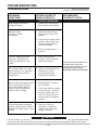
TROUBLESHOOTING
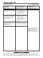
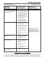
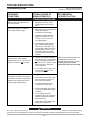
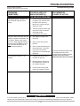
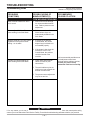
How To Use Troubleshooting Guide
WARNING
This Troubleshooting Guide is designed to be used by the machine Owner/Operator. Unauthorized repairs
performed on this equipment may result in danger to the technician and machine operator and will invalidate your
factory warranty. For your safety, please observe all safety notes and precautions detailed in the Safety Section of
this manual to avoid electrical shock or danger while troubleshooting this equipment.
___________________________________________________________________________________________
This Troubleshooting Guide is provided to help you
locate and correct possible machine misadjustments.
Simply follow the three-step procedure listed below.
Step 1. LOCATE PROBLEM (SYMPTOM)
Look under the column labeled “PROBLEM
(SYMPTOMS)”. This column describes possible
symptoms that your machine may exhibit. Find the
listing that best describes the symptom that your
machine is exhibiting.
Step 3. CONSULT LOCAL AUTHORIZED FIELD
SERVICE FACILITY
If you have exhausted all of the recommended tests in
step 2, consult your local Authorized Field Service
Facility.
Step 2. PERFORM EXTERNAL RECOMMENDED
TESTS
The second column labeled “POSSIBLE AREAS OF
MISADJUSTMENT(S)” lists the obvious external
possibilities that may contribute to the machine
symptom. Perform these tests/checks in the order
listed. In general, these tests can be conducted
without removing the case wrap-around cover.
CAUTION
If for any reason you do not understand the test procedures or are unable to perform the tests/repairs safely,
contact your local Authorized Field Service Facility for technical troubleshooting assistance before you proceed.
– 27 –
TROUBLESHOOTING
Troubleshooting Guide
PROBLEMS
(SYMPTOMS)
Observe Safety Guidelines
detailed in the beginning of this manual.
POSSIBLE AREAS OF
MISADJUSTMENT(S)
RECOMMENDED
COURSE OF ACTION
OUTPUT PROBLEMS
Major Physical or Electrical
Damage is Evident.
1. Contact The Lincoln Electric
Service Dept. (216) 383-2531
Machine is Dead No Output - No Fan
No Displays.
1. Make certain that the input
power switch is in the “ON”
position.
2. Check the input voltage at the
machine. Input voltage must
match the rating plate and
reconnect the panel.
3. Blown or missing fuses in
input line.
Fan runs - Display and control
panel dark. No output from
machine in either Stick or TIG
modes.
1. Check for proper input
voltages. As per nameplate
and reconnect panel.
The voltmeter reads “00” in Stick
Mode, and there is no output from
the machine when in the TIG
2-Step Mode.
1. Inspect to assure that the arc
start switch is in the on
(closed) position when
welding in the TIG Mode.
Machine does not respond (no gas
flow, no high frequency and no
open circuit voltage) when arc
switch or amptrol is activated displays and fan working.
1. Machine MUST be in one of
the TIG Modes.
115VAC Receptacle not working
properly (voltage is below 108VAC).
Machine has welding output - fan is
running.
1. Check for 115VAC at
receptacle - if low (below
108VAC), then check input
voltage to machine.
If all recommended possible areas
of misadjustment have been
checked and the problem persists,
Contact your local Lincoln
Authorized Field Service Facility.
2. The arc start switch or amptrol
may be defective. Check for
continuity between pins “D”
and “E” on cable connector
when arc switch or amptrol is
activated.
CAUTION
If for any reason you do not understand the test procedures or are unable to perform the tests/repairs safely,
contact your local Authorized Field Service Facility for technical troubleshooting assistance before you proceed.
– 28 –
TROUBLESHOOTING
Troubleshooting Guide
Observe Safety Guidelines
detailed in the beginning of this manual.
PROBLEMS
(SYMPTOMS)
POSSIBLE AREAS OF
MISADJUSTMENT(S)
RECOMMENDED
COURSE OF ACTION
OUTPUT PROBLEMS
Machine regularly over heats thermostat opens, PL1 (yellow light
on front panel) glows. The fan runs
but machine has no output and no
display.
1. Welding application may
exceed recommended duty
cycle.
2. Dirt and dust may have
clogged the cooling channels
inside the machine. Blow out
unit with clean, dry
compressed air.
3. Air intake and exhaust louvers
may be blocked due to
inadequate clearance around
machine.
Machine makes a very loud
buzzing noise in DC Stick Mode, or
in DC TIG Mode when the arc start
or amptrol is pressed.
1. Inspect output stud insulators
for cracks or signs of overheating.
If all recommended possible areas
of misadjustment have been
checked and the problem persists,
Contact your local Lincoln
Authorized Field Service Facility.
There is no current draw from
machine’s output studs.
(The machine is not externally
loaded).
CAUTION
If for any reason you do not understand the test procedures or are unable to perform the tests/repairs safely,
contact your local Authorized Field Service Facility for technical troubleshooting assistance before you proceed.
– 29 –
TROUBLESHOOTING
Troubleshooting Guide
PROBLEMS
(SYMPTOMS)
Observe Safety Guidelines
detailed in the beginning of this manual.
POSSIBLE AREAS OF
MISADJUSTMENT(S)
RECOMMENDED
COURSE OF ACTION
FUNCTION PROBLEMS
The yellow light (PL1) on the front
panel is not lit.
1. Normal condition - this light
will glow only if machine is in
an overheated condition.
(Thermal overload).
One or more keypad lights (LEDS)
are dark and cannot be lit when
their respective keys are pressed machine is operable.
1. Be sure that the proper weld
mode is selected. For
example, the high frequency
keys and keypad lights
(LEDS) are not active in the
stick mode.
The Beeper (Piezoelectric Buzzer)
cannot be heard - machine
operating normally.
1. Background noise may be too
loud for user to hear beeper.
If all recommended possible areas
of misadjustment have been
checked and the problem persists,
Contact your local Lincoln
Authorized Field Service Facility.
CAUTION
If for any reason you do not understand the test procedures or are unable to perform the tests/repairs safely,
contact your local Authorized Field Service Facility for technical troubleshooting assistance before you proceed.
– 30 –
TROUBLESHOOTING
Troubleshooting Guide
Observe Safety Guidelines
detailed in the beginning of this manual.
PROBLEMS
(SYMPTOMS)
POSSIBLE AREAS OF
MISADJUSTMENT(S)
RECOMMENDED
COURSE OF ACTION
TIG MODE PROBLEMS
Machine output is intermittently
lost. Gas flow and high frequency
are also interrupted.
1. Problem may be caused by
high frequency interference.
Make sure that the machine is
grounded properly according
to the installation instructions.
If there are other high
frequency sources in the area,
make certain that they are
grounded properly.
2. Check arc start switch or
amptrol for proper operation
and loose connections.
Arc “Flutters” when TIG welding.
1. Tungsten electrode may be
too large in diameter.
2. Tungsten not “Sharp” when
welding in DC negative mode.
3. If helium is used as a
shielding gas, then reduce the
percentage of helium.
4. Adjust flow rate of shielding
gas.
If all recommended possible areas
of misadjustment have been
checked and the problem persists,
Contact your local Lincoln
Authorized Field Service Facility.
5. Check hoses and connections
for leaks.
Lack of penetration in AC TIG
welding.
1. Manual balance control set
improperly - set to negative
10 (-10) for maximum
penetration.
Black areas along weld bead.
1. Tungsten electrode may be
contaminated. Replace or
sharpen.
2. Shielding gas flow may be
insufficient.
3. Contaminated gas or faulty
gas line or torch.
Black areas along weld bead at or
near end of weld.
1. Increase post flow time.
CAUTION
If for any reason you do not understand the test procedures or are unable to perform the tests/repairs safely,
contact your local Authorized Field Service Facility for technical troubleshooting assistance before you proceed.
– 31 –
TROUBLESHOOTING
Troubleshooting Guide
PROBLEMS
(SYMPTOMS)
Observe Safety Guidelines
detailed in the beginning of this manual.
POSSIBLE AREAS OF
MISADJUSTMENT(S)
RECOMMENDED
COURSE OF ACTION
TIG WELDING PROBLEMS
Machine has low output when in
TIG 4-Step Mode.
1. Machine must be in “Local”
Control Mode when 4-Step is
used.
Weak high frequency - machine
has normal welding output.
1. Spark gap may be misadjusted.
Check and reset per
maintenance instructions.
2. Improper shielding gas flow.
Adjust for a flow of 10 to 30
CFH (4.7 to 14.1 l/min.) for
most applications.
3. Work and electrode cables in
poor condition allowing high
frequency to “Leak Off”. Use
good quality cables with a high
natural rubber content, such
as Lincoln Stable Arc Cable.
Cables should be as short as
possible.
The display shows zero amps, but
indicates open circuit voltage
(approximately 53V). The arc start
switch or amptrol is not actuated.
1. The arc start switch or amptrol
may be defective. There should
not be any continuity between
pins “D” and “E” on the arc start
cable connector, unless the
unit is actuated.
If all recommended possible areas
of misadjustment have been
checked and the problem persists,
Contact your local Lincoln
Authorized Field Service Facility.
2. If an amptrol is not being used,
the machine must be in the
Local Control Mode.
High frequency “Spark” is present
at tungsten electrode, but operator
is unable to establish a welding arc.
Machine has normal open circuit
voltage (approximately 53V).
1. Torch may be faulty.
2. If an amptrol is not being used,
then the machine must be in
the Local Control Mode.
3. Tungsten electrode may be
too large for the process.
4. If helium shielding gas is being
used, then reduce percentage
of helium.
5. If TIG welding in the DC
negative mode, then a properly
sharpened thoriated tungsten
should be used.
6. Check the welding cables and
output stud connections.
CAUTION
If for any reason you do not understand the test procedures or are unable to perform the tests/repairs safely,
contact your local Authorized Field Service Facility for technical troubleshooting assistance before you proceed.
– 32 –
TROUBLESHOOTING
Troubleshooting Guide
Observe Safety Guidelines
detailed in the beginning of this manual.
PROBLEMS
(SYMPTOMS)
POSSIBLE AREAS OF
MISADJUSTMENT(S)
RECOMMENDED
COURSE OF ACTION
TIG WELDING PROBLEMS
No high frequency. Machine is in
the TIG Mode and has normal
output.
1. In order for the high frequency
to operate, the machine must
be either in the start only
Mode or the continuous high
frequency mode.
2. The high frequency spark gap
may be too large or shorted.
Check gap as per
maintenance instructions.
No gas or water flow when arc start
switch or amptrol is activated in the
TIG Mode. Machine has output fan runs. When toggling between
the Stick and TIG Modes a “Click”
can be heard indicating that the
solenoids are operating.
Arc rectification when AC TIG
welding.
1. Gas supply is empty or not
turned on.
2. Gas or water hose may be
pinched.
3. Gas or water solenoid may be
blocked with dirt. Use filters
to prevent reoccurrence.
Consult your Local welder/gas
distributor.
1. Tungsten electrode may be
too small for process.
If all recommended possible areas
of misadjustment have been
checked and the problem persists,
Contact your local Lincoln
Authorized Field Service Facility.
2. Manual balance control may
be misadjusted. Readjust to
the negative direction.
3. If helium gas is being used,
reduce percentage of helium.
CAUTION
If for any reason you do not understand the test procedures or are unable to perform the tests/repairs safely,
contact your local Authorized Field Service Facility for technical troubleshooting assistance before you proceed.
– 33 –
TROUBLESHOOTING
Troubleshooting Guide
PROBLEMS
(SYMPTOMS)
Observe Safety Guidelines
detailed in the beginning of this manual.
POSSIBLE AREAS OF
MISADJUSTMENT(S)
RECOMMENDED
COURSE OF ACTION
STICK WELDING PROBLEMS
Stick electrode “Blasts Off” when
arc is struck.
1. Weld current is set too high
for recommended electrode
size. Reduce preset current
adjustment.
Cannot adjust AC Wave Balance
when welding in the Stick Mode.
1. This is a normal condition.
Wave balance keys are
automatically disabled in the
Stick Mode.
Machine welds at a very low output
regardless of the preset current
setting - arc is stable.
1. If welding in the Remote
Control Mode, the remote
amptrol may be defective or
not installed properly.
2. If the output is low when the
machine is in the Local
Control Mode, the problem
could be internal to the
machine.
Variable or sluggish welding arc
when welding in the Stick Mode.
1. Check work and electrode
cables for loose or poor
connections.
If all recommended possible areas
of misadjustment have been
checked and the problem persists,
Contact your local Lincoln
Authorized Field Service Facility.
2. The weld cables may be too
small or too long to permit the
desired current to flow.
3. The preset current adjustment
may be set too low.
CAUTION
If for any reason you do not understand the test procedures or are unable to perform the tests/repairs safely,
contact your local Authorized Field Service Facility for technical troubleshooting assistance before you proceed.
– 34 –
– 35 –
239A
230B
240
239
230C
229A
229
238A
237
238
C2
235A
X1
R4
236A
R3
230
236
235
231
230D
C1
230E
232
232B
52A
MACHINES ONLY
50/60 HZ
(1,3)
(1,1)
(1,2)
(5,1)
(4,1)
(2,2)
(2,1)
PIEZO
(5,2)
(4,2)
(3,1)
BUZZER
(-)
(+)
TO KEYPAD MATRIX
G2719
4-19-96D
NOTE: This diagram is for reference only. It may not be accurate for all machines covered by this manual. The specific diagram for a particular code is pasted inside
the machine on one of the enclosure panels. If the diagram is illegible, write to the Service Department for a replacement. Give the equipment code number..
TO GROUND PER NATIONAL ELECTRIC CODE
WIRING DIAGRAM - SQUARE WAVE TIG 255 CODE 10022, 10023 & 10024
WIRING DIAGRAM
– 36 –
239A
231B
240
239
231C
229A
229
238A
237
238
C2
235A
X1
235
236
R4
236A
R3
232
231
C1
231
231D
52
232B
232C
50
MACHINES ONLY
50/60 HZ
(1,3)
(1,1)
(1,2)
(5,1)
(4,1)
(2,2)
(2,1)
PIEZO
(5,2)
(4,2)
(3,1)
BUZZER
(-)
(+)
TO KEYPAD MATRIX
G3302
1-24-97H
NOTE: This diagram is for reference only. It may not be accurate for all machines covered by this manual. The specific diagram for a particular code is pasted inside
the machine on one of the enclosure panels. If the diagram is illegible, write to the Service Department for a replacement. Give the equipment code number..
TO GROUND PER NATIONAL ELECTRIC CODE
WIRING DIAGRAM - SQUARE WAVE TIG 255 CODE 10451, 10452 & 10453
WIRING DIAGRAM
Now Available...12th Edition
The Procedure Handbook of Arc Welding
New Lessons in Arc Welding
This printing will go fast so don’t delay. Place your
order now using the coupon below.
Lessons, simply written, cover manipulatory techniques;
machine and electrode characteristics; related subjects,
such as distortion; and supplemental information on arc
welding applications, speeds and costs. Practice materials,
exercises, questions and answers are suggested for each
lesson.
The hardbound book contains over 750 pages of welding
information, techniques and procedures. Much of this material
has never been included in any other book.
528 pages, well illustrated, 6” x 9” size, bound in simulated,
gold embossed leather.
$5.00 postage paid U.S.A. Mainland
With over 500,000 copies of previous editions published
since 1933, the Procedure Handbook is considered by many to
be the “Bible” of the arc welding industry.
A must for all welders, supervisors, engineers and
designers. Many welding instructors will want to use the book
as a reference for all students by taking advantage of the low
quantity discount prices which include shipping by
4th class parcel post.
$15.00 postage paid U.S.A. Mainland
Need Welding Training?
How To Read Shop Drawings
The book contains the latest information and application
data on the American Welding Society Standard Welding
Symbols. Detailed discussion tells how engineers and
draftsmen use the “short-cut” language of symbols to pass
on assembly and welding information to shop personnel.
Practical exercises and examples develop the reader’s ability
to visualize mechanically drawn objects as they will appear
in their assembled form.
The Lincoln Electric Company operates the oldest and
most respected Arc Welding School in the United States at its
corporate headquarters in Cleveland, Ohio. Over 100,000
students have graduated. Tuition is low and the training is
“hands on”
For details write:
Lincoln Welding School
22801 St. Clair Ave.
Cleveland, Ohio 44117-1199.
and ask for bulletin ED-80 or call 216-383-2259 and ask for the
Welding School Registrar.
187 pages with more than 100 illustrations. Size 8-1/2” x 11”
Durable, cloth-covered board binding.
$4.50 postage paid U.S.A. Mainland
Lincoln Welding School
BASIC COURSE
5 weeks of fundamentals
$700.00
There is a 10% discount on all orders of $50.00 or more for shipment at one time to one location.
Orders of $50 or less before discount or orders outside of North America must be prepaid with charge, check or money order in U.S. Funds Only.
Prices include shipment by 4 th Class Book Rate for U.S.A. Mainland Only. Please allow up to 4 weeks for delivery.
UPS Shipping for North America Only. All prepaid orders that request UPS shipment please add:
$5.00
For order value up to $49.99
$10.00
For order value between $50.00 & $99.99
$15.00
For order value between $100.00 & $149.00
For North America invoiced orders over $50.00 & credit card orders, if UPS is requested, it will be invoiced or charged to you at cost.
Outside U.S.A. Mainland order must be prepaid in U.S. Funds. Please add $2.00 per book for surface mail or $15.00 per book for air parcel post shipment.
METHOD OF PAYMENT: (Sorry, No C.O.D. Orders)
Name:
_______________________________________________
CHECK ONE:
Please Invoice (only if order is over $50.00)
Check or Money Order Enclosed, U.S. Funds only
Credit Card MasterCard
VISA
Address:
_______________________________________________
_______________________________________________
Telephone: _______________________________________________
®
®
Account No.
|_|_|_|_|_|_|_|_|_|_|_|_|_|_|_|_|_|_|_|_|_|
USE THIS FORM TO ORDER:
BOOKS OR FREE INFORMATIVE CATALOGS
Lincoln Welding School
(ED-80)
Seminar Information
(ED-45)
Educational Video Information
(ED-93)
James F. Lincoln Arc Welding
Foundation Book Information
(JFLF-515)
Order from:
Exp Date
|_|_|
|_|_|
Month
Year
Signature as it appears on Charge Card:
______________________
BOOK DIVISION, The Lincoln Electric Company, 22801 St. Clair Avenue, Cleveland, Ohio 44117-1199
Telephone: 216-383-2211 or, for fastest service, FAX this completed form to: 216-361-5901.
Titles:
Price
New Lessons in Arc Welding
$5.00
Procedure Handbook “Twelfth Edition”
$15.00
How to Read Shop Drawings
$4.50
Incentive Management
$5.00
A New Approach to Industrial Economics $5.00
The American Century of John C. Lincoln $5.00
Welding Preheat Calculator
$3.00
Pipe Welding Charts
$4.50
Code
L
PH
H
IM
NA
AC
WC-8
ED-89
Quantity
SUB TOTAL
Additional Shipping Costs if any
TOTAL COST
Cost
● Do not touch electrically live parts or
WARNING
Spanish
AVISO DE
PRECAUCION
French
ATTENTION
German
WARNUNG
Portuguese
ATENÇÃO
● Keep flammable materials away.
● Wear eye, ear and body protection.
● Mantenga el material combustible
● Protéjase los ojos, los oídos y el
electrode with skin or wet clothing.
● Insulate yourself from work and
ground.
● No toque las partes o los electrodos
bajo carga con la piel o ropa
mojada.
● Aislese del trabajo y de la tierra.
● Ne laissez ni la peau ni des
vêtements mouillés entrer en contact
avec des pièces sous tension.
● Isolez-vous du travail et de la terre.
● Berühren Sie keine stromführenden
fuera del área de trabajo.
● Gardez à l’écart de tout matériel
inflammable.
● Entfernen Sie brennbarres Material!
Teile oder Elektroden mit Ihrem
Körper oder feuchter Kleidung!
● Isolieren Sie sich von den
Elektroden und dem Erdboden!
● Não toque partes elétricas e
electrodos com a pele ou roupa
molhada.
● Isole-se da peça e terra.
cuerpo.
● Protégez vos yeux, vos oreilles et
votre corps.
● Tragen Sie Augen-, Ohren- und Kör-
perschutz!
● Mantenha inflamáveis bem
guardados.
● Use proteção para a vista, ouvido e
corpo.
Japanese
Chinese
Korean
Arabic
READ AND UNDERSTAND THE MANUFACTURER’S INSTRUCTION FOR THIS EQUIPMENT AND THE CONSUMABLES TO BE
USED AND FOLLOW YOUR EMPLOYER’S SAFETY PRACTICES.
SE RECOMIENDA LEER Y ENTENDER LAS INSTRUCCIONES DEL FABRICANTE PARA EL USO DE ESTE EQUIPO Y LOS
CONSUMIBLES QUE VA A UTILIZAR, SIGA LAS MEDIDAS DE SEGURIDAD DE SU SUPERVISOR.
LISEZ ET COMPRENEZ LES INSTRUCTIONS DU FABRICANT EN CE QUI REGARDE CET EQUIPMENT ET LES PRODUITS A
ETRE EMPLOYES ET SUIVEZ LES PROCEDURES DE SECURITE DE VOTRE EMPLOYEUR.
LESEN SIE UND BEFOLGEN SIE DIE BETRIEBSANLEITUNG DER ANLAGE UND DEN ELEKTRODENEINSATZ DES
HERSTELLERS. DIE UNFALLVERHÜTUNGSVORSCHRIFTEN DES ARBEITGEBERS SIND EBENFALLS ZU BEACHTEN.
● Keep your head out of fumes.
● Use ventilation or exhaust to
● Turn power off before servicing.
● Do not operate with panel open or
guards off.
remove fumes from breathing zone.
● Los humos fuera de la zona de
respiración.
● Mantenga la cabeza fuera de los
humos. Utilice ventilación o
aspiración para gases.
● Gardez la tête à l’écart des fumées.
● Utilisez un ventilateur ou un
aspirateur pour ôter les fumées des
zones de travail.
● Vermeiden Sie das Einatmen von
Schweibrauch!
● Sorgen Sie für gute Be- und
Entlüftung des Arbeitsplatzes!
● Mantenha seu rosto da fumaça.
● Use ventilação e exhaustão para
remover fumo da zona respiratória.
● Desconectar el cable de
alimentación de poder de la
máquina antes de iniciar cualquier
servicio.
● Débranchez le courant avant
l’entretien.
● Strom vor Wartungsarbeiten
abschalten! (Netzstrom völlig
öffnen; Maschine anhalten!)
● No operar con panel abierto o
guardas quitadas.
● N’opérez pas avec les panneaux
ouverts ou avec les dispositifs de
protection enlevés.
● Anlage nie ohne Schutzgehäuse
oder Innenschutzverkleidung in
Betrieb setzen!
● Não opere com as tampas removidas.
● Desligue a corrente antes de fazer
● Mantenha-se afastado das partes
serviço.
● Não toque as partes elétricas nuas.
● Não opere com os paineis abertos
moventes.
WARNING
Spanish
AVISO DE
PRECAUCION
French
ATTENTION
German
WARNUNG
Portuguese
ATENÇÃO
ou guardas removidas.
Japanese
Chinese
Korean
Arabic
LEIA E COMPREENDA AS INSTRUÇÕES DO FABRICANTE PARA ESTE EQUIPAMENTO E AS PARTES DE USO, E SIGA AS
PRÁTICAS DE SEGURANÇA DO EMPREGADOR.
C
3
ON
TR
PER
▲▲▲▲▲
▲
LIN
▲
C
OL
YEAR
R
A
NC
S22127-2
R
E PLUS P
TI
C
INCLUDING: PARTS
& LABOR
E
FO
WARRANTY
M
▲▲▲▲▲
▲
▲ IC
▲
▲▲ ▲▲
▲ N ELE
O
T
▲
▲▲ ▲▲
▲
LIMITED WARRANTY
TO OBTAIN WARRANTY COVERAGE:
The Lincoln Electric Company (Lincoln) warrants to the
original purchaser (end-user) of new equipment that it will
be free of defects in workmanship and material.
You are required to notify Lincoln Electric, your Lincoln
Distributor, Lincoln Service Center or Field Service Shop of
any defect within the warranty period. Written notification is
recommended.
NT
SE Y
E SU
IM P
W ER
S
1 SED
ED
STATEMENT OF WARRANTY:
This warranty is void if Lincoln finds that the equipment
has been subjected to improper care or abnormal
operation.
WARRANTY REPAIR:
All warranty periods date from the date of shipment to the
original purchaser and are as follows:
If Lincoln's inspection of the equipment confirms the
existence of a defect covered by this warranty, the defect
will be corrected by repair or replacement at Lincoln's
option.
Three Years:
WARRANTY COSTS:
WARRANTY PERIOD:
W
AR
RA
Transformer Welders
Motor-generator Welders
Inverter Welders
Automatic Wire Feeders
Semiautomatic Wire Feeders
Plasma-cutting Power Source
Engine Driven Welders (except engine and engine
accessories) with operating speed under 2,000 RPM
You must bear the cost of shipping the equipment to a
Lincoln Service Center or Field Service Shop as well as
return shipment to you from that location.
IMPORTANT WARRANTY LIMITATIONS:
• Lincoln will not accept responsibility for repairs made
without its authorization.
Two Years:
Engine Driven Welders (except engine, engine
accessories and Power-Arc 4000 generator/welders)
with operating speed over 2,000 RPM
All engine and engine accessories are warranted by the
engine or engine accessory manufacturer and are not
covered by this warranty.
One Year:
Equipment not listed above such as gun and cable
assemblies, water coolers, FAS TRAK or MIG-TRAK
equipment, Power-Arc 4000 generator/welders, Wire Feed
Module (Factory Installed) and field-installed optional
equipment.
• Lincoln shall not be liable for consequential damages
(such as loss of business, etc.) caused by the defect or
reasonable delay in correcting the defect.
• Lincoln's liability under this warranty shall not exceed
the cost of correcting the defect.
• This written warranty is the only express warranty
provided by Lincoln with respect to its products.
Warranties implied by law such as the Warranty of
Merchantability are limited to the duration of this
limited warranty for the equipment involved.
March, ‘96
World's Leader in Welding and Cutting Products
Premier Manufacturer of Industrial Motors
• Sales and Service through Subsidiaries and Distributors Worldwide •
22801 St. Clair Ave. Cleveland, Ohio 44117-1199 U.S.A. Tel. 216-481-8100