1
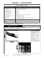
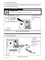
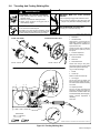
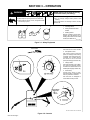
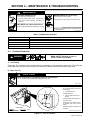
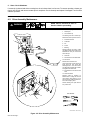
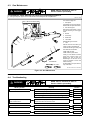
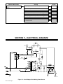
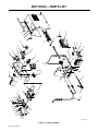
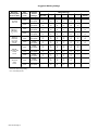
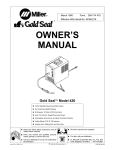
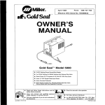
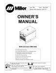
October 1997 Form: OM-174 470B Effective With Serial No. KH531011 OWNER’S MANUAL Gold Seal Model 420 CV/DC Welding Power Source/Wire Feeder For FCAW And GMAW Welding 90 Amperes, 18 Volts At 20% Duty Cycle Uses 115 Volts AC, Single-Phase Input Power Overheating, Short-Circuit, And Motor Overload Protection Usable Range Of 30 To 130 Amperes Includes Gun, Welding Wire, And Gas Valve Read and follow these instructions and all safety blocks carefully. Give this manual to the operator. Have only trained and qualified persons install, operate, or service this unit. For help, call your distributor Call your distributor if you do not understand the directions. or: MILLER ELECTRIC Mfg. Co., P.O. Box 1079, Appleton, WI 54912 414-734-9821 cover 7/93 – ST-155 507-A 1997 MILLER Electric Mfg. Co. PRINTED IN USA The following safety alert symbol and signal words are used throughout this manual to call attention to and identify different levels of hazard and special instructions. WARNING WARNING statements identify procedures or practices which must be followed to avoid serious personal injury or loss of life. CAUTION CAUTION statements identify procedures or practices which must be followed to avoid minor personal injury or damage to this equipment. ARC WELDING SAFETY PRECAUTIONS WARNING ARC WELDING can be hazardous. PROTECT YOURSELF AND OTHERS FROM POSSIBLE SERIOUS INJURY OR DEATH. KEEP CHILDREN AWAY. PACEMAKER WEARERS KEEP AWAY UNTIL CONSULTING YOUR DOCTOR. In welding, as in most jobs, exposure to certain hazards occurs. Welding is safe when precautions are taken. The safety information given below is only a summary of the more complete safety information that will be found in the Safety Standards listed on the next page. Read and follow all Safety Standards. HAVE ALL INSTALLATION, OPERATION, MAINTENANCE, AND REPAIR WORK PERFORMED ONLY BY QUALIFIED PEOPLE. ELECTRIC SHOCK can kill. Touching live electrical parts can cause fatal shocks or severe burns. The electrode and work circuit is electrically live whenever the output is on. The input power circuit and machine internal circuits are also live when power is on. In semiautomatic or automatic wire welding, the wire, wire reel, drive roll housing, and all metal parts touching the welding wire are electrically live. Incorrectly installed or improperly grounded equipment is a hazard. 1. Do not touch live electrical parts. 2. Wear dry, hole-free insulating gloves and body protection. 3. Insulate yourself from work and ground using dry insulating mats or covers. ARC RAYS can burn eyes and skin; NOISE can damage hearing. Arc rays from the welding process produce intense heat and strong ultraviolet rays that can burn eyes and skin. Noise from some processes can damage hearing. FUMES AND GASES can be hazardous to your health. Welding produces fumes and gases. Breathing these fumes and gases can be hazardous to your health. 1. Keep your head out of the fumes. Do not breath the fumes. 2. If inside, ventilate the area and/or use exhaust at the arc to remove welding fumes and gases. 3. If ventilation is poor, use an approved air-supplied respirator. 4. Read the Material Safety Data Sheets (MSDSs) and the manufacturer’s instruction for metals, consumables, coatings, and cleaners. 4. Disconnect input power or stop engine before installing or servicing this equipment. 5. Properly install and ground this equipment according to its Owner’s Manual and national, state, and local codes. 6. Turn off all equipment when not in use. 7. Do not use worn, damaged, undersized, or poorly spliced cables. 8. Do not wrap cables around your body. 9. Ground the workpiece to a good electrical (earth) ground. 10. Do not touch electrode while in contact with the work (ground) circuit. 11. Use only well-maintained equipment. Repair or replace damaged parts at once. 12. Wear a safety harness to prevent falling if working above floor level. 13. Keep all panels and covers securely in place. 1. Wear a welding helmet fitted with a proper shade of filter (see ANSI Z49.1 listed in Safety Standards) to protect your face and eyes when welding or watching. 2. Wear approved safety glasses. Side shields recommended. 3. Use protective screens or barriers to protect others from flash and glare; warn others not to watch the arc. 4. Wear protective clothing made from durable, flame-resistant material (wool and leather) and foot protection. 5. Use approved ear plugs or ear muffs if noise level is high. 5. Work in a confined space only if it is well ventilated, or while wearing an air-supplied respirator. Shielding gases used for welding can displace air causing injury or death. Be sure the breathing air is safe. 6. Do not weld in locations near degreasing, cleaning, or spraying operations. The heat and rays of the arc can react with vapors to form highly toxic and irritating gases. 7. Do not weld on coated metals, such as galvanized, lead, or cadmium plated steel, unless the coating is removed from the weld area, the area is well ventilated, and if necessary, while wearing an air-supplied respirator. The coatings and any metals containing these elements can give off toxic fumes if welded. WELDING can cause fire or explosion. Sparks and spatter fly off from the welding arc. The flying sparks and hot metal, weld spatter, hot workpiece, and hot equipment can cause fires and burns. Accidental contact of electrode or welding wire to metal objects can cause sparks, overheating, or fire. 1. Protect yourself and others from flying sparks and hot metal. 2. Do not weld where flying sparks can strike flammable material. 3. Remove all flammables within 35 ft (10.7 m) of the welding arc. If this is not possible, tightly cover them with approved covers. 4. Be alert that welding sparks and hot materials from welding can easily go through small cracks and openings to adjacent areas. FLYING SPARKS AND HOT METAL can cause injury. Chipping and grinding cause flying metal. As welds cool, they can throw off slag. CYLINDERS can explode if damaged. Shielding gas cylinders contain gas under high pressure. If damaged, a cylinder can explode. Since gas cylinders are normally part of the welding process, be sure to treat them carefully. 1. Protect compressed gas cylinders from excessive heat, mechanical shocks, and arcs. 2. Install and secure cylinders in an upright position by chaining them to a stationary support or equipment cylinder rack to prevent falling or tipping. 5. Watch for fire, and keep a fire extinguisher nearby. 6. Be aware that welding on a ceiling, floor, bulkhead, or partition can cause fire on the hidden side. 7. Do not weld on closed containers such as tanks or drums. 8. Connect work cable to the work as close to the welding area as practical to prevent welding current from traveling long, possibly unknown paths and causing electric shock and fire hazards. 9. Do not use welder to thaw frozen pipes. 10. Remove stick electrode from holder or cut off welding wire at contact tip when not in use. 11. Wear oil-free protective garments such as leather gloves, heavy shirt, cuffless trousers, high shoes, and a cap. 1. Wear approved face shield or safety goggles. Side shields recommended. 2. Wear proper body protection to protect skin. 3. Keep cylinders away from any welding or other electrical circuits. 4. Never allow a welding electrode to touch any cylinder. 5. Use only correct shielding gas cylinders, regulators, hoses, and fittings designed for the specific application; maintain them and associated parts in good condition. 6. Turn face away from valve outlet when opening cylinder valve. 7. Keep protective cap in place over valve except when cylinder is in use or connected for use. 8. Read and follow instructions on compressed gas cylinders, associated equipment, and CGA publication P-1 listed in Safety Standards. PRINCIPAL SAFETY STANDARDS Safety in Welding and Cutting, ANSI Standard Z49.1, from American Welding Society, 550 N.W. LeJeune Rd, Miami FL 33126 Safety and Health Standards, OSHA 29 CFR 1910, from Superintendent of Documents, U.S. Government Printing Office, Washington, D.C. 20402. Recommended Safe Practices for the Preparation for Welding and Cutting of Containers That Have Held Hazardous Substances, American Welding Society Standard AWS F4.1, from American Welding Society, 550 N.W. LeJeune Rd, Miami, FL 33126 National Electrical Code, NFPA Standard 70, from National Fire Protection Association, Batterymarch Park, Quincy, MA 02269. Safe Handling of Compressed Gases in Cylinders, CGA Pamphlet P-1, from Compressed Gas Association, 1235 Jefferson Davis Highway, Suite 501, Arlington, VA 22202. Code for Safety in Welding and Cutting, CSA Standard W117.2, from Canadian Standards Association, Standards Sales, 178 Rexdale Boulevard, Rexdale, Ontario, Canada M9W 1R3. Safe Practices For Occupation And Educational Eye And Face Protection, ANSI Standard Z87.1, from American National Standards Institute, 1430 Broadway, New York, NY 10018. Cutting And Welding Processes, NFPA Standard 51B, from National Fire Protection Association, Batterymarch Park, Quincy, MA 02269. Ref. sr1 2/92 TABLE OF CONTENTS SECTION 1 – SPECIFICATIONS SECTION 4 – MAINTENANCE & TROUBLESHOOTING 1-1. Volt-Ampere Curve And Duty Cycle Chart . . . . . . . 1 SECTION 2 – INSTALLATION 2-1. Installing Work Clamp . . . . . . . . . . . . . . . . . . . . . . . . 2-2. Installing Gas Supply . . . . . . . . . . . . . . . . . . . . . . . . 2-3. Connecting Input Power . . . . . . . . . . . . . . . . . . . . . . 2-4. Gun Polarity For Wire Type . . . . . . . . . . . . . . . . . . . 2-5. Installing Welding Gun . . . . . . . . . . . . . . . . . . . . . . . 2-6. Threading And Feeding Welding Wire . . . . . . . . . . 2 2 2 3 3 4 SECTION 3 – OPERATION . . . . . . . . . . . . . . . . . . . . . . . 5 4-1. 4-2. 4-3. 4-4. Overload Protection . . . . . . . . . . . . . . . . . . . . . . . . . . Drive Assembly Maintenance . . . . . . . . . . . . . . . . . . Gun Maintenance . . . . . . . . . . . . . . . . . . . . . . . . . . . . Troubleshooting . . . . . . . . . . . . . . . . . . . . . . . . . . . . . 6 7 8 8 SECTION 5 – ELECTRICAL DIAGRAM . . . . . . . . . . . . . 9 SECTION 6 – PARTS LIST Figure 6-1. Main Assembly . . . . . . . . . . . . . . . . . . . . . . . . . 11 Figure 6-2. MWG-160M Gun . . . . . . . . . . . . . . . . . . . . . . . 12 SECTION 1 – SPECIFICATIONS Table 1-1. Welding Power Source Specifications Description Type Of Output Direct Current/Constant Voltage (DC/CV) Rated Weld Output 90 Amperes, 18 Volts DC, 20% Duty Cycle Type Of Input Power Single-Phase; 60 Hz; At 115 Volts AC Input Amperes At Rated Output 20 A At 115 V KVA/KW Used At Rated Output 3 kVA/2.2 kW Max. Open-Circuit Voltage 30 Volts DC Control Circuit Voltage At Gun 24 Volts DC Welding Processes Gas Metal Arc (GMAW) And Flux Cored Arc Welding (FCAW) Calculated Speed Range At No Load 283 To 716 ipm (7.1 To 17.9 mpm) Wire Diameter Range .023 To .035 in (0.58 To 0.89 mm) Overall Dimensions Length: 16-1/2 in (419 mm); Width: 9-1/2 in (241 mm); Height: 17 in (432 mm) Weight Net: 73 lb (33 kg); Ship: 80 lb (36 kg) Welding Gun Rated Output (Air-Cooled) 160 Amperes At 60% Duty Cycle Using CO2 Shielding Gas Cable Length 10 ft (3 m) 1-1. Volt-Ampere Curve And Duty Cycle Chart CAUTION USING GUN BEYOND DUTY CYCLE RATING can damage gun. • • Do not use gun beyond rated amperage when using CO2 shielding gas. Use gun at 30% duty cycle when using mixed shielding gas. wfwarn8.1 10/91 The volt-ampere curves show the minimum and maximum voltage and amperage output capabilities of the welding power source. Curves of other settings fall between the curves shown. Duty cycle is how long the unit can operate within a ten minute period without causing overheating or damage. This unit is rated at 20% duty cycle allowing welding 2 minutes out of every 10 minutes. This gun is rated at 60% duty cycle when using CO2 shielding gas and 30% when using mixed shielding gas. ssb1.1 10/91 – SB-124 646-A / sb1.3 10/91 – SB-124 655-A Figure 1-1. Volt-Ampere Curve And Duty Cycle Chart OM-174 470 Page 1 SECTION 2 – INSTALLATION 2-1. Installing Work Clamp 1 2 3 4 1 Insulator Bolt Smaller Hole Work Clamp Tabs Bend tabs around work cable. 6 5 6 2 Work Cable From Unit Nut 5 3 Tools Needed: 4 3/8, 7/16 in Ref. ST-025 190-D Figure 2-1. Installing Work Clamp 2-2. Installing Gas Supply WARNING CYLINDERS can explode if damaged. • • • BUILDUP OF SHIELDING GAS can harm health or kill. Keep cylinders away from welding and other electrical circuits. Never touch cylinder with welding electrode. • Shut off shielding gas supply when not in use. Always secure cylinder to running gear, wall, or other stationary support. warn4.1 9/91 Chain gas cylinder to running gear, wall, or other stationary support so cylinder cannot fall and break off valve. 1 1 2 3 4 5 2 4 Fitting has threads. 3 6 OR 1 Argon Gas Or Mixed Gases 2 5 6 Tools Needed: 1-1/8, 5/8 in 3 7 Cap Cylinder Valve Cylinder Regulator/Flowmeter Gas Hose Connection 5/8-18 right-hand Flow Adjust Typical flow rate is 20 cfh (cubic feet per hour). Check wire manufacturer’s recommended flow rate. Make sure flow adjust is closed when opening cylinder to avoid damage to the flowmeter. 7 8 CO2 Adapter O-Ring Install adapter with O-ring between regulator/flowmeter and CO2 cylinder. 8 ssb3.1* 5/94 – ST-158 697-A / Ref. ST-149 827-B Figure 2-2. Typical CO2 Regulator/Flowmeter Installation OM-174 470 Page 2 2-3. Connecting Input Power Connect unit to a properly grounded receptacle of a 20 ampere individual branch circuit protected by time-delay fuses or circuit breakers. Select an extension cord of 12 AWG for up to 75 ft (23 m) or 10 AWG for up to 140 ft (46 m). 2-4. Gun Polarity For Wire Type WARNING ELECTRIC SHOCK can kill. • • Do not touch live electrical parts. Turn Off welding power source, and disconnect input power before inspecting or installing. swarn1.1 2/93 1 STRAIGHT POLARITY REVERSE POLARITY For Solid Steel Or Aluminum Wires (GMAW) Process) For Flux Cored Wires (FCAW Process) DCEN 1 Polarity Changeover Label 2 Polarity Jumper Links Always read and follow welding wire manufacturer’s recommended polarity. Close door. DCEP GUN POLARITY CHANGEOVER S-116 599 2 Tools Needed: 3/8 in Ref. ST-155 506–A Figure 2-3. Gun Polarity Connections 2-5. Installing Welding Gun 3 1 Gun Securing Nut 2 Drive Assembly 3 Gun End Loosen securing nut. Insert end through front panel opening until it bottoms against drive assembly. Tighten nut. 4 Gun Trigger Plug Insert plug into receptacle, and tighten threaded collar. Close door. 4 Tools Needed: 1 2 5/16 in Ref. ST-155 506-A Figure 2-4. Gun Connections OM-174 470 Page 3 2-6. Threading And Feeding Welding Wire WARNING CYLINDERS can explode if damaged. • • • WELDING WIRE can cause puncture wounds. Keep cylinders away from welding and other electrical circuits. Never touch cylinder with welding electrode. Always secure cylinder to running gear, wall, or other stationary support. • • ELECTRIC SHOCK can kill. Do not press gun trigger until instructed to do so. Do not point gun toward any part of the body, other people, or any metal when threading welding wire. HOT SURFACES can burn skin. • • Do not touch live electrical parts. The welding wire, drive rolls, drive assembly, and all metal parts touching the welding wire are electrically live when welding or feeding wire using gun trigger. TO USE 1 LB SPOOL: Allow gun to cool before touching. swarn5.1 10/91 / swarn2.1 9/91 TO USE Standard Wire Reel: 1 Wire Spool 2 Hub Tension Nut Grasp spool in one hand and turn while using a wrench to adjust nut. When a slight force is needed to turn spool, tension is set. Loosen wire from spool, cut off bent wire, and pull 6 in (150 mm) of wire from spool. 3 Pressure Adjustment Open pressure assembly. Part No. 135 615 Part No. 183 312 4 Wire Inlet Guide 5 Drive Roll 6 Wire Outlet Guide Thread wire through inlet guide, along drive roll groove, and into outlet guide. Close pressure assembly. Lay gun cable out straight. 7 Nozzle 8 Contact Tip Remove nozzle and contact tip. 9 Turn On unit, press gun trigger, and feed 2 in (55 mm) of wire out of gun. Turn Off unit and reinstall contact tip and nozzle. 3 1 2 3 Gun Trigger 4 10 Adjusting Pressure 5 Turn On unit and check drive roll pressure by feeding wire against a wood board or concrete surface; wire should feed steadily without slipping. 6 Tighten pressure necessary. adjustment if Close door. 9 8 Tools Needed: 9/16 in 7 10 WOOD ST-800 316 / Ref. ST- 155 505-A / Ref. ST-155 504-A / S-0627-A Figure 2-5. Feeding Welding Wire OM-174 470 Page 4 SECTION 3 – OPERATION READ SAFETY BLOCKS at beginning of manual before proceeding. WARNING MOVING PARTS can cause injury. • • ARCING can damage switch. • Keep away from pinch points such as drive rolls. Keep all doors, panels, covers, and guards closed and securely in place. 1 Do not change Voltage switch position while welding. Arcing inside switch can damage contacts, causing switch to fail. 2 3 1 Insulating Gloves 2 Safety Glasses With Side Shields 3 Welding Helmet Wear dry insulating gloves, safety glasses with side shields, and a welding helmet with a correct shade of filter (see ANSI Z49.1). sb3.1 10/91 Figure 3-1. Safety Equipment 1 Tools Needed: Power Switch Use switch to turn unit On and Off. 2 2 1 Wire Speed Control Use control to select a wire feed speed. As Voltage switch setting increases, wire speed range also increases. The numbers around the control are not a wire feed speed (see last page of Parts List). 3 Voltage Switch Use switch to select an arc voltage. The higher the selected number, the thicker the material that can be welded (see last page of Parts List). 4 Work Clamp Connect work clamp to clean, paint-free location on workpiece, as close as possible to weld area. Use wire brush or sandpaper to clean metal at weld joint area. 3 4 Ref. ST-155 508-A / Ref. ST-182 488 Figure 3-2. Controls OM-174 470 Page 5 SECTION 4 – MAINTENANCE & TROUBLESHOOTING WARNING ELECTRIC SHOCK can kill. • • MOVING PARTS can cause injury. • • Do not touch live electrical parts. Turn Off welding power source, and disconnect input power before inspecting, maintaining, or servicing. Keep away from moving parts. Keep away from pinch points such as drive rolls. HOT PARTS can cause severe burns. • Allow cooling period before maintaining or servicing. Maintenance and troubleshooting to be performed only by qualified persons. swarn8.2* 2/93 Table 4-1. Maintenance Schedule Time Maintenance Before each use. Tighten all connections. Check gun and clean nozzle. After each spool of wire. Blow out gun liner. Clean and check wire drive parts; replace as necessary. Every 3 months. Tape or replace cracked cables; clean and tighten connections. Replace unreadable labels. Every 6 months. Blow out or vacuum inside of unit. 4-1. Overload Protection READ SAFETY BLOCKS at start of Section 4 before proceeding. WARNING A. Overheating Thermostat TP1 protects the unit from damage due to overheating. If main transformer gets too hot, TP1 opens and weld output stops, but fans keep running to cool transformer. Wait several minutes before trying to weld. B. Motor Fuse F1 CAUTION STATIC ELECTRICITY can damage parts on circuit boards. • Put on grounded wrist strap BEFORE handling boards or parts. fwarn5.1* 9/91 1 2 Turn Off and unplug unit. Unlatch door, remove handle, and remove door/wrapper. 1 Circuit Board PC1 Located behind fan. 2 Fuse F1 (See Parts List For Rating) If this fuse opens, the wire drive motor does not run. Pull fuse from fuse holder on PC1. To reinstall, push fuse into fuse holder. Reinstall wrapper and handle, and latch door. Tools Needed: 3/8 in Ref. ST-155 640 / ST-149 327 Figure 4-1. Fuse F1 Location OM-174 470 Page 6 C. Short Circuit Shutdown If contact tip is shorted and sticks to workpiece, the unit shuts down, but fan runs. To resume operation, release gun trigger, turn Off unit, and remove contact tip from workpiece. Check contact tip and replace if damaged. Turn On unit to continue operation. 4-2. Drive Assembly Maintenance READ SAFETY BLOCKS at start of Section 4 before proceeding. WARNING Turn Off and unplug unit. 1 Wire Spool 2 Gun Contact Tip Cut welding wire off at contact tip. Retract wire onto spool and secure. 1 3 Pressure Roll Arm 4 Cotter Pin 5 Pin 6 Screw 7 Bearing Remove bearing as shown. Install new bearing and secure with screw. Reinstall arm onto pin and secure with cotter pin. 8 Setscrew 9 Smooth Groove For Hard Wire 10 Drive Roll 2 Remove drive roll as shown. Use a wire brush to clean drive roll. Push drive roll onto shaft with desired groove in. Turn drive roll so one setscrew faces flat side of shaft, and tighten both setscrews. 11 Knurled Groove For Flux-Cored Wire 3 5 12 Wire Inlet Guide 6 Remove guide by pressing on barbed area or cutting off one end near housing and pulling it out of hole. Push new guide into hole from rear until it snaps in place. 7 Thread welding wire (see Section 2-6). Close door. 4 8 9 Tools Needed: 11 10 12 8 5/64 in ST-155 504-A / ST-154 199 Figure 4-2. Drive Assembly Maintenance OM-174 470 Page 7 4-3. Gun Maintenance READ SAFETY BLOCKS at start of Section 4 before proceeding. WARNING FLYING METAL CHIPS AND DIRT can cause injury and damage equipment. • Point gun away from people and in a safe direction when blowing out with compressed air. swarn10.1 10/91 Turn Off and unplug unit. 1 Wire Spool Cut welding wire off at contact tip. Retract wire onto spool and secure. 2 Gun Securing Nut Disconnect trigger leads. Loosen nut and remove gun and trigger leads. 3 1 2 3 Nozzle 4 Contact Tip 5 Head Tube 6 Liner Collet Disassemble gun as shown. 4 7 5 6 Liner Pull liner from this end. Blow gun casing out with compressed air. Insert new liner into gun casing until even with end of head tube. 7 Install collet onto liner. 6 Install contact tip and nozzle. 7 Tools Needed: 3/8, 5/16 in Insert gun into feeder and mark where liner touches drive roll. Remove gun and cut liner off. Reinstall gun so that liner is as close as possible to drive rolls without touching. Thread welding wire (see Section 2-6). Close door. Ref. ST-155 506–A / ST-155 509-A Figure 4-3. Gun Maintenance 4-4. Troubleshooting READ SAFETY BLOCKS at start of Section 4 before proceeding. WARNING Welding Trouble No weld output; wire does not feed. Remedy Secure power cord plug in receptacle. Motor fuse F1 open, replace F1. Section 2-3 4-1B Replace building line fuse or reset circuit breaker if open. –– Secure gun trigger leads or repair leads, or replace trigger switch. 2-5 No weld output; wire does not feed; fan motor continues to run. Thermostat TP1 open (overheating). Allow fan to run; the thermostat will close when the unit has cooled. 4-1A No weld output; wire feeds. Connect work clamp to get good metal to metal contact. Low weld output. Figure 3-2 Replace contact tip. 4-3 Connect unit to proper input voltage or check for low line voltage. 2-3 OM-174 470 Page 8 Wire Drive/Gun Trouble Electrode wire feeding stops during welding. Remedy Section Straighten gun cable and/or replace damaged parts. 4-3 Adjust drive roll pressure. 2-6 Readjust hub tension. 2-6 Replace contact tip if blocked. Clean or replace wire inlet guide or liner if dirty or plugged. Replace drive roll or pressure bearing if worn or slipping. Secure gun trigger leads or repair leads, or replace trigger switch. Check and replace F1. Check and clear any restrictions at drive assembly and liner. Have nearest Factory Authorized Service Station/Service Distributor check drive motor. 4-3 4-2, 4-3 4-2 2-5 4-1B 4-2, 4-3 –– SECTION 5 – ELECTRICAL DIAGRAM SB-162 261-A Figure 5-1. Circuit Diagram For Welding Power Source OM-174 470 Page 9 NOTES OM-174 470 Page 10 2 1 3 OM-174 470 Page 11 17 4 16 5 6 7 10 9 Figure 6-1. Main Assembly 11 Fig 6-2 51 8 50 12 14 13 21 15 22 20 52 18 49 19 48 38 23 37 39 24 36 35 47 25 26 34 28 46 27 45 44 43 40 33 29 32 31 42 41 30 SECTION 6 – PARTS LIST ST-155 532-A Parts For Main Assembly NOTE: All items indented by a dot(s) are included with the item listed directly above. Item Part No. No. 1 2 149 332 147 635 131 315 151 828 112 031 090 443 111 622 154 827 602 169 092 237 090 415 085 244 085 242 010 224 058 549 129 893 173 446 090 416 124 817 153 727 111 929 135 615 010 910 073 355 010 909 111 998 134 201 119 539 3 4 5 6 7 8 9 10 11 12 13 14 15 16 17 18 19 20 21 22 23 24 25 Item Part No. No. Description Hose Clamp Hose Drive Assembly · Cotter Hair Pin · Pressure Lever · Bearing · · Spacer · Drive Roll · Set Screw · Knob · Spring · Cupped Washer · Fastener · Spring Pin · Wire Guide · Insulator · Drive Motor · Hinge Pin · Drive Housing Baffle Hub Bushing, .390 ID x .750 OD Washer Spring Nut Cotter Hair Pin Stand-Off Support Circuit Card 26 27 28 29 30 31 32 33 34 35 36 37 38 *073 426 118 936 079 747 006 393 111 931 005 656 153 729 154 596 +153 724 134 464 089 899 120 675 129 696 119 264 010 047 122 385 174 504 39 116 996 605 227 147 545 111 443 000 101 097 922 111 997 111 897 127 023 Description · Fuse, slo-blo 5A Housing, 10 pin Terminal Relay Fan Motor Fan Blade Handle Cap, Handle Wrapper Warning Label Latch Bracket Contactor Rectifier Tubing Terminal Assembly · Link Case w/Cmpts · Gas Valve · Nyl Nut, gas valve · Cord Set · Bushing, cord set · Rheostat · Knob · Rocker Switch, SPST · Rotary Switch · · Knob 9 52 155 530 182 488 111 644 025 338 153 722 125 552 147 676 181 649 090 288 162 264 022 160 118 457 019 663 600 325 153 969 110 740 173 374 183 581 048 282 183 312 7 5 4 3 10 1 15 14 16 13 17 1 2 12 18 19 ST-110 832-D · Case · Nameplate · Bushing, .875mtg · Bushing, .625mtg Side Panel Thermostat, NC Transformer Resistor Varistor Capacitor Clamp Stabilizer Foot Cable Clamp GA-16 Gun, (Fig 6-2) Regulator/Flowmeter Hose, gas Connector Adapter ring, wire spool +When ordering a component originally displaying a precautionary label, the label should also be ordered. Be sure to provide Model and Serial Number when ordering replacement parts. 8 1 Description *Recommended Spare Parts. 1 2 3 4 5 6 7 8 6 11 40 41 42 43 44 45 46 47 48 49 50 51 Part No. Item Part No. No. 8 2 Item No. 8 9 9 9 10 11 12 13 14 15 16 17 18 19 110 793 110 795 110 780 110 779 110 781 128 878 118 571 110 785 ♦110 786 ♦110 787 110 789 ♦112 420 ♦110 790 110 794 080 565 110 792 110 797 167 440 110 784 079 974 110 796 079 878 048 834 Description Handle Assembly, black Head Tube · Nut · Jacket · Stop · Adapter · Spring Contact Tip, .023 Contact Tip, .030 Contact Tip, .035 Nozzle, 1/2 orf Nozzle, 3/8 orf Nozzle, flat spot Trigger Switch Assembly Terminal Cable/Conduit Sleeve Liner, .023-.035 · Collet, .035 O-Ring, .500 Connector Connector & Pins Connector ♦OPTIONAL Figure 6-2. GA-16 Gun (Fig 6-1 Item 52) OM-174 470 Page 12 Suggested Welding Settings Wire Type, Shielding Gas, And Flow Rate Metal Thickness Wire Diameter (inch) Operator Control Settings* 1/8 in. (3.2 mm) 12 ga. 14 ga. 16 ga. 0.030 Voltage Wire Speed 4 30 3 30 3 20 1 25 0.035 Voltage Wire Speed 4 30 3 25 2 25 ER70S-6, Mild Steel, CO2, 20 cfh+ 0.023 Voltage Wire Speed 4 50 4 50 0.030 Voltage Wire Speed 4 40 ER70S-6, Mild Steel, 75% Argon 25% CO2, 20 cfh+ 0.023 Voltage Wire Speed 0.030 E-71T-GS Flux Core ER 308, Stainless Steel, Tri-Mix, 20 cfh+ Aluminum, Argon, 30 cfh+ 20 ga. 22 ga. And Thinner 1 20 1 20 – – 1 25 1 25 1 20 – – 3 50 2 45 2 40 1 30 1 30 4 40 3 40 3 40 2 40 1 40 1 35 4 60 4 55 3 50 2 45 2 40 1 35 1 35 Voltage Wire Speed 4 50 4 50 3 50 3 50 2 45 1 45 1 40 0.023 Voltage Wire Speed 4 40 4 35 4 35 3 30 3 30 2 20 – – 0.030 Voltage Wire Speed 4 30 4 30 4 30 3 25 3 20 2 15 – – 0.035 Voltage Wire Speed 4 15 4 15 4 15 3 15 2 15 – – – – 0.030 Voltage Wire Speed – – 4 85 3 80 2 75 1 70 – – – – 0.035 Voltage Wire Speed – – 4 55 4 60 2 60 2 55 – – – – 18 ga. *Do not change VOLTAGE switch position while welding. WIRE SPEED value in table is a starting value only, and WIRE SPEED control setting can be fine tuned during welding. +cfh = cubic feet per hour OM-174 470 Page 13 Effective January 1, 1997 (Equipment with a serial number preface of “KH” or newer) This limited warranty supersedes all previous Miller warranties and is exclusive with no other guarantees or warranties expressed or implied. LIMITED WARRANTY – Subject to the terms and conditions below, Miller Electric Mfg. Co., Appleton, Wisconsin, warrants to its original retail purchaser that new Miller equipment sold after the effective date of this limited warranty is free of defects in material and workmanship at the time it is shipped by Miller. THIS WARRANTY IS EXPRESSLY IN LIEU OF ALL OTHER WARRANTIES, EXPRESS OR IMPLIED, INCLUDING THE WARRANTIES OF MERCHANTABILITY AND FITNESS. Within the warranty periods listed below, Miller will repair or replace any warranted parts or components that fail due to such defects in material or workmanship. Miller must be notified in writing within thirty (30) days of such defect or failure, at which time Miller will provide instructions on the warranty claim procedures to be followed. Miller shall honor warranty claims on warranted equipment listed below in the event of such a failure within the warranty time periods. All warranty time periods start on the date that the equipment was delivered to the original retail purchaser, or one year after the equipment is sent to a North American distributor or eighteen months after the equipment is sent to an International distributor. 1. 2. 5 Years Parts – 3 Years Labor * Original main power rectifiers * Inverters (input and output rectifiers only) 3 Years — Parts and Labor * Transformer/Rectifier Power Sources * Plasma Arc Cutting Power Sources * Semi-Automatic and Automatic Wire Feeders * Inverter Power Supplies Warranty Questions? * Intellitig Call 1-800-4-AMILLER for your local Miller distributor. * Robots * Engine Driven Welding Generators (NOTE: Engines are warranted separately by the engine manufacturer.) 3. 1 Year — Parts and Labor * Motor Driven Guns (w/exception of Spoolmate 185) * Process Controllers * Positioners and Controllers * Automatic Motion Devices * Orbital Weld Heads * IHPS Power Sources * Water Coolant Systems * HF Units * Grids * Spot Welders * Load Banks * SDX Transformers * Miller Cyclomatic Equipment * Running Gear/Trailers * Plasma Cutting Torches (except APT, ZIPCUT & PLAZCUT Models) * Deutz Engines (outside North America) * Field Options (NOTE: Field options are covered under True Blue for the remaining warranty period of the product they are installed in, or for a minimum of one year — whichever is greater.) 4. 6 Months — Batteries 5. 90 Days — Parts and Labor * MIG Guns/TIG Torches * APT, ZIPCUT & PLAZCUT Model Plasma Cutting Torches * Remote Controls * Accessory Kits * Replacement Parts (No labor) * Spoolmate 185 Miller’s True Blue Limited Warranty shall not apply to: 1. Items furnished by Miller, but manufactured by others, such as engines or trade accessories. These items are covered by the manufacturer’s warranty, if any. 2. Consumable components; such as contact tips, cutting nozzles, contactors, brushes, slip rings, relays or parts that fail due to normal wear. 3. Equipment that has been modified by any party other than Miller, or equipment that has been improperly installed, improperly operated or misused based upon industry standards, or equipment which has not had reasonable and necessary maintenance, or equipment which has been used for operation outside of the specifications for the equipment. MILLER PRODUCTS ARE INTENDED FOR PURCHASE AND USE BY COMMERCIAL/INDUSTRIAL USERS AND PERSONS TRAINED AND EXPERIENCED IN THE USE AND MAINTENANCE OF WELDING EQUIPMENT. In the event of a warranty claim covered by this warranty, the exclusive remedies shall be, at Miller’s option: (1) repair; or (2) replacement; or, where authorized in writing by Miller in appropriate cases, (3) the reasonable cost of repair or replacement at an authorized Miller service station; or (4) payment of or credit for the purchase price (less reasonable depreciation based upon actual use) upon return of the goods at customer’s risk and expense. Miller’s option of repair or replacement will be F.O.B., Factory at Appleton, Wisconsin, or F.O.B. at a Miller authorized service facility as determined by Miller. Therefore no compensation or reimbursement for transportation costs of any kind will be allowed. TO THE EXTENT PERMITTED BY LAW, THE REMEDIES PROVIDED HEREIN ARE THE SOLE AND EXCLUSIVE REMEDIES. IN NO EVENT SHALL MILLER BE LIABLE FOR DIRECT, INDIRECT, SPECIAL, INCIDENTAL OR CONSEQUENTIAL DAMAGES (INCLUDING LOSS OF PROFIT), WHETHER BASED ON CONTRACT, TORT OR ANY OTHER LEGAL THEORY. ANY EXPRESS WARRANTY NOT PROVIDED HEREIN AND ANY IMPLIED WARRANTY, GUARANTY OR REPRESENTATION AS TO PERFORMANCE, AND ANY REMEDY FOR BREACH OF CONTRACT TORT OR ANY OTHER LEGAL THEORY WHICH, BUT FOR THIS PROVISION, MIGHT ARISE BY IMPLICATION, OPERATION OF LAW, CUSTOM OF TRADE OR COURSE OF DEALING, INCLUDING ANY IMPLIED WARRANTY OF MERCHANTABILITY OR FITNESS FOR PARTICULAR PURPOSE, WITH RESPECT TO ANY AND ALL EQUIPMENT FURNISHED BY MILLER IS EXCLUDED AND DISCLAIMED BY MILLER. Some states in the U.S.A. do not allow limitations of how long an implied warranty lasts, or the exclusion of incidental, indirect, special or consequential damages, so the above limitation or exclusion may not apply to you. This warranty provides specific legal rights, and other rights may be available, but may vary from state to state. In Canada, legislation in some provinces provides for certain additional warranties or remedies other than as stated herein, and to the extent that they may not be waived, the limitations and exclusions set out above may not apply. This Limited Warranty provides specific legal rights, and other rights may be available, but may vary from province to province.