1
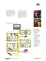
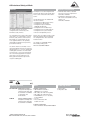
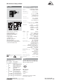
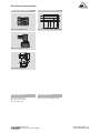
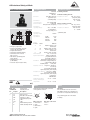
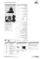
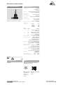
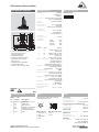
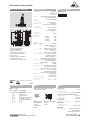
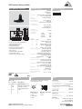
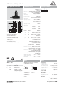
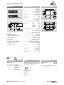
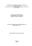
Safety Bus System
AS-Interface Safety at Work
R
S
IPEC Industrial Controls Ltd.
17-109 Fernstaff Court, Concord, Ont. L4K 3M1
C
OR
Phone: 905-738-6688
www.ipecautomation.com
AS-Interface Safety at Work ®
AS-Interface SaW
Easy and safe
Industrial Controls Ltd.
2IPEC
17-109 Fernstaff Court, Concord, Ont. L4K 3M1
AS-Interface Safety at Work
(SaW) is the first safety bus
system based upon the open
standard of AS-International.
Safety components such as
Emergency Stop command devices, safety switches, solenoid
interlocks or safety light barriers
are simply connected to the
yellow AS-Interface cable. For
the evaluation of the safety
signals a “Safety Monitor” is
merely added to the ASInterface system.
Safe transmission mechanism
The communication protocol for
safety relevant applications is
based on the unchanged ASInterface Standard transmission.
With each AS-Interface master
call each safety device answers
in return with a preset data telegram. This information is analysed and in case of a deviation
from the pre-set values the
enabling fields are opened. The
maximum response time for a
safe shutdown is 40 ms.
AS-Interface Standard in
accordance with EN 50295
With the integration of AS-Interface SaW the AS-Interface network will continue to operate
unchanged. The well known
components, like the standard
AS-Interface master, the standard power supply as well as the
AS-Interface yellow cable will
still form the basis of all ASInterface installations. Therefore
safety functions can be easily
added to an exiting machine
equipped with AS-Interface SaW.
Cost reduction with
AS-Interface Safety at Work
Reduce cost and installation
time – A never ending story.
During installation and machine
commissioning as well as during
maintenance, AS-Interface SaW
supports the user with integrated system diagnosis. It provides detailed information about
the cause and place of the failure, and enables the user to
quickly find and analyse a malfunction and therefore minimise
machine downtime. With ASInterface Safety at Work you
can directly reduce your cost.
The heart of safety
The safety monitor analyses all
transmitted information from
each safety device on the ASInterface network and, in case of
a safety device being activated
or in case of a fault in one of the
safety devices, the safety monitor immediately shuts down to
create a safe condition. The
safety monitor is equipped with
one or two redundant pairs of
enabling paths for applications
up to Control Category 4 according to EN 954-1.
Each safety function of the monitor can be set with simple drag &
drop software. Afterwards the
parameters are downloaded into
the safety monitor and protected
with a password.
More flexibility with
AS-Interface Safety at Work
For the realisation of individual
safety solutions, SCHMERSAL
offers the maximum amount of
flexibility with its diverse range
of safety devices. Depending on
the application the user can
choose the optimal solution out
of an extensive product basket.
As AS-Interface SaW is an open
system, the user has also the
possibility to include additional
Safety components from other
suppliers. AS-Interface Safety
at Work fulfils the safety requirements to the highest standards.
Phone: 905-738-6688
www.ipecautomation.com
R
S
Less installation time with
AS-Interface Safety at Work
Easier and quicker with ASInterface SaW: Choose a Safety
device – Connect it to the yellow
AS-Interface cable – Set the
safety function in the safety
monitor. – That’s it.
C
OR
No further settings are required
at each of the safety devices,
the bulky parallel wire cables
between the safety devices in
the field and the switching cabinet
are reduced and wiring time is
decreased. The power supply
for all safety sensors is supplied
over the single yellow AS-Interface cable.
AS-Interface Safety at Work overview
Controller
AS-Interface
Power
Master
Safety monitor
Safety guard monitoring
Two-Hand Control
E-Stop Command
AS-Interface SaW
System Features
• Up to 31 standard and
safety slaves on the
AS-Interface system
• No Safety PLC
necessary
• Safety-relevant signals
can be allocated into
groups and multiple
Safety monitors may
be connected
• Response time is
max. 40 ms
• Safety-relevant signals
can be integrated into
plant diagnostics
• Certified up to Control
Category 4 in accordance
with EN 954-1
• Certified by the TÜV
(German Technical
Inspectorate)
Foot switch
Standard AS-Interface Module
IPEC Industrial Controls Ltd.
17-109 Fernstaff Court, Concord, Ont. L4K 3M1
Phone: 905-738-6688
www.ipecautomation.com 3
AS-Interface Safety at Work
R
S
ASM
C
OR
Technical data
Standards:
Control category:
Enclosure:
Mounting:
Screw terminals:
Protection class:
• Safety monitor
• Control Category 4 to EN 954-1
• Monitor for AS-Interface SaW compatible
safety device, i.e. safety switches, solenoid
interlocks, Emergency-Stop buttons,
2-Hand control, light grid and light curtains
• AS-Interface connection
• One or two redundant pairs
of enabling paths
• Additional outputs (transistor,
short-circuit proof)
• Configurable functions: AND logical
element, OR logical element,
Start devices, Start-up test
• Edge-sensitive start push button
• Feedback circuit to monitor
external contactors
• LEDs to diplay switching conditions
• Operating voltage 24 VDC
EN 50295, EN 61496-1 (1997), IEC/EN 60204-1, EN 954-1, IEC 61508
4
Polyamide PA 66, black
snaps onto standard DIN rail to EN 50022
max. 2.5 mm2 (incl. conductor ferrules)
terminals IP 20
enclosure IP 20
Ub:
24 VDC ± 15 %
Residual ripple:
< 15%
Ib:
ASM E1-R2: 0,15 A
ASM E2-R2/R2: 0,2 A
Switch-on peak current:
600 mA
AS-Interface operating voltage:
18.5 ... 31.6 V
AS-Interface operating current:
< 45 mA
AS-Interface specification:
Profile - Monitor 7.F
Configuration interface:
RS232: 9600 baud, no parity, 1 start bit, 1 stop bit, 8 data bits
Inputs:
1.Y1,1.Y2
Input signal:
„Y1, Y2“: le < 10 mA at 24 VDC (opto coupler, high-active)
Outputs:
ASM E1-R2: 1.13/14,1.23/24, 1 enabling path (redundant);
ASM E2-R2/R2: 1.13/14,1.23/24, 2.13/14, 2.23/24,
2 enabling paths (redundant)
Utilisation category:
AC-15, DC-13
Ie/Ue:
3 A / 230 VAC
1 A / 24 VDC
Switching voltage:
max. 230 VAC
Ithe:
3 A per output circuit
Max. fuse rating:
4 A (slow blow), external
Additional outputs:
transistor outputs, 200 mA total,
short-circuit proof-type, positive-switching
Switch-on time:
< 10 s
Response time:
< 40 ms
Indications:
AS-Interface: voltage LED green,
communication LED red;
Enabling paths: LED green, yellow, red
EMC rating:
conforming to EMC Directive
Overvoltage category:
III to DIN VDE 0110
Resistance to vibration:
5 ... 55 Hz / amplitude 0.35 mm
± 15 % at the regulation point
Resistance to shock:
10 g / 16 ms
Ambient temperature:
– 20 °C … + 60 ºC
Storage and transport temperature:
– 30 °C … + 70 ºC
Weight:
ASM E1-R2: approx. 350 g;
ASM E2-R2/R2: approx. 450 g
Note:
Inductive loads (e.g. contactors, relays, etc.) are
to be suppressed by means of a suitable circuit.
Approvals
F C D
C
Ordering details
ASM E ➀
No.
Replace
Description
➀
1-R2
1 enabling field
(redundant)
2 enabling fields
(redundant)
2-R2/R2
Note
The safety monitors ASM E1-R2 and ASM E2-R2/R2 evaluate all transmitted information from
each safety device on the AS-Interface network. For the safe guarding of different applications
various AS-Interface Safety at Work compatible safety devices are needed, i.e. safety switches,
solenoid interlocks, safety sensors, E-stop buttons as well as safe input modules.
The AS-Interface Safety at Work can be used in applications up to control category 4 according
to EN 954-1 with the appropriate safety devices and systems.
Industrial Controls Ltd.
4IPEC
17-109 Fernstaff Court, Concord, Ont. L4K 3M1
Phone: 905-738-6688
www.ipecautomation.com
AS-Interface Safety at Work
R
S
• The installation of different safety areas is
possible with numerous safety monitors
working alongside each other. The maximum
number of safety devices including the safety
monitors may not exceed 31 participants.
• The allocation of the safety devices to one or
more safety monitors is achieved with the
help of the configuration software ”asimon“.
• The wiring diagram shows the safety monitor
ASM E2-R2/R2 with start-pushbuttons and
feedback loops.
• No safety devices are displayed, because
they are installed in the field i.e. on the safety
guards itself. The data connection between
the safety monitor and the decentralised
safety slaves is established via the ASInterface network.
• For the operation of AS-Interface Safety at
Work system, a standard controller, an ASInterface Master and AS-Interface power
supply, must always be used in the
application.
• With the RJ 45 connector the safety monitor
is configured and started up.
OR
Wiring diagram
+ 24 VDC
+ 24 VDC
0V
L1
S2
S1
AS-iAS-i+
M1
AS-i+ AS-i-
1Y1
ASInterface
1Y2
2Y1
1.32
2Y2
M2
2.32
1.13
1.23
2.13
2.23
1.14
1.24
2.14
2.24
K1
K3
RJ 45
Note
C
RS
232
K2
K4
24 V
L+
M
FE
2.14
2.24
L1 L2 L3
K5
+ 24 VDC
K6
0V
L1 L2 L3
K7
K5
N
3
M
K7
K8
K6
N
K8
3
M
• Start push button H
A start push button (NO) can optionally be
connected to the ASM. With the guard
door(s) closed, the enabling paths are then
not closed until the start push button has
been operated. If neither start button nor
feedback circuit are required, then no
connections are required to the terminals
(1Y1/2, 2Y1/2).
• Output expander module
For additional contacts by means of more
enabling paths and potential-free indication
contacts an output expander module is
connected to the safety monitor, i.e. to the
internal ASM enabling path. For the control
of the additional outputs the ASM feedback
loop is utilised.
IPEC Industrial Controls Ltd.
17-109 Fernstaff Court, Concord, Ont. L4K 3M1
Phone: 905-738-6688
www.ipecautomation.com 5
AS-Interface Safety at Work
R
S
asimon
C
OR
System components
Following the successful configuration and
download, the safety monitor and the safety
devices can be tested and monitored with
asimon.
The software asimon is a tool for the
configuration and commissioning of the
AS-Interface safety monitors.
The configuration of the safety monitor and its
safety devices, i.e. E-Stop buttons, solenoid
interlocks, safety switches, 2-Hand controls,
light curtains etc. is performed by an easyto-use graphical interface. Thus providing
safeguarding of hazardous areas present by
power-driven machinery.
The following functions are available with
the asimon software:
• Configuration of different safety devices
• Configuration of start-modules
• Configuration logical combinations
(AND, OR, RS Flip-Flops)
• Configuration of the feedback loops
• Configuration of the operating methods
• Configuration of the system-modules
• Print out of Configuration protocol
• Download cable: Interface cable with
two RJ 45 connectors, Length: 0.10 m
Part-number: ASM-DC1
• Configuration cable: Interface cable
with one RJ 45 and SUBD 9 connector,
Length: 1.2 m
Part-number: ASM-KC1
Asimon can be used offline as well as online
during development and project planning.
The configuration files can be saved and
loaded as desired.
The software is compatibable with the
Microsoft® operating system
Windows 95/98/ME/NT/2000/XP.
The asimon offers the user a library of icons
representing different safety devices and other
functional devices, i.e. one or two independent
enabling paths, automatic or monitored start,
stop category 0 or 1 etc. For the implementation of a new safety application the required
safety devices are selected from the icon
library, parameterised and assigned to the
respective enabling path.
Approvals
F
C
Ordering details
SET ASM-SWP ASM-startup-package:
Configuration and diagnostic
software package with online
documentation on CD-ROM,
a configuration- and
downloadcable
ASM-CD
asimon software package:
Configuration and diagnosticsoftware package with online
documentation on CD-ROM
Note
Hardware requirements:
• 200 MHz INTEL Pentium® or
AMD® Processor or quicker
• Min. 8 Mbyte free main memory (RAM)
• Min. 8 Mbyte free hard disk memory
• A CD-ROM drive (or 3 1/2 “ disc drive)
for the installation
• A mouse
• A free serial interface with
9 SubD-connection
Ordering details
Download cable
Configuration cable
ASM-DC1
ASM-KC1
Software requirements:
• Microsoft Windows ® 95/98/ME/NT/2000/XP
Industrial Controls Ltd.
6IPEC
17-109 Fernstaff Court, Concord, Ont. L4K 3M1
Phone: 905-738-6688
www.ipecautomation.com
AS-Interface Safety at Work
R
30
• Safety switch with separate actuator
• Integrated AS-Interface
• AS-Interface LED status display
• AS-Interface M12 connector
• Address jack (optional)
• Thermoplastic enclosure
• Coded actuator
• Long life
• Protection class IP 67
Inputs:
Contact
1
Straight actuator AZ 15/16-B1
10
a
16
R min. 45
) 50 mA
Profile
IO-Code:
ID-Code:
ID-Code2:
S-0.B
0x0
0xB
0xE
56
40
ø 5,5
a
27
Status
on
Data bits
D0/D1 = dynamic code
transmission
1
off
D0/D1 = static code “00”
2
on
D2/D3 = dynamic code
transmission
2
off
D2/D3 = static code “00”
Parameter bits:
P0 … P3 not used
Input module address:
default on address 0,
programmable via the
AS-Interface Master or
Hand-held programming device
Indications:
AS-Interface:
voltage LED green,
communication LED red
Enabling status:
LED yellow
Mechanical life:
> 1 million operations
EMC rating:
conforming to
EMC Directive
Ambient temperature:
– 25 °C … + 60 ºC
Storage and transport
temperature:
– 25 °C … + 85 ºC
Flexible actuator AZ 15/16-B2
R min. 38
16
M 12 52
9
13
M 12
27
56
40
R min. 25
ø 5,5
11
90
15,5 7
5,5
AS-Interface
operating current:
AS-Interface
specification:
connector M12 x 1
IP 67
26.5 ... 31.6 VDC,
via AS-Interface,
reverse-polarity proof
R min. 15
0
7
40
29
18
8
ø 5,5
27,3
14
8
AS-Interface
connection type:
Protection class:
AS-Interface
operating voltage:
16
5
11
Enclosure:
R min. 15
0
56
40
5
EN 50295
EN 60947-5-1
EN 954-1
glass-fibre reinforced
thermoplastic,
self-extinguishing
27,3
Standards:
System components
28,3
Technical data
7
AZ 16 AS
C
OR
S
27
Flexible actuator AZ 15/16-B6
Approvals
F C D
C
Ordering details
AZ 16➀ -AS➁➂
No.
Replace
Description
➀
ST1
ST2
ST3
Connector (middle)
Connector (right)
Connector (left)
No latching
Latching 30 N
Latching 5 N
No address jack
Address jack
➁
➂
r
r-2254
b
Note
1
2
Ordering details
4
3
M12 connector:
1: AS-Interface +
2: spare
3: AS-Interface –
4: spare
IPEC Industrial Controls Ltd.
17-109 Fernstaff Court, Concord, Ont. L4K 3M1
Straight actuator
Flexible actuator
Flexible actuator
AZ 15/16-B1
AZ 15/16-B2
AZ 15/16-B6
Further actuators can be found in the chapter
„Safety switches with separate actuator“,
see page 1-8.
Actuators must be ordered separately.
Phone: 905-738-6688
www.ipecautomation.com 7
AS-Interface Safety at Work
R
S
AZM 161 AS
Technical data
Standards:
AS-Interface
connection type:
Protection class:
AS-Interface
operating voltage:
40
78
72
AS-Interface
operating current:
29
6
18
8
6
90
6
5,5
6
7
AS-Interface
specification:
b
a
M12
130
56
M12
30
• Solenoid interlock
• Integrated AS-Interface
• AS-Interface LED status display
• AS-Interface M12 connector
• Magnetic drive through AS-Interface output
• Solenoid power supply via the
AS-Interface network or via an external
24 VDC power supply (p version)
• Address jack (optional)
• Thermoplastic enclosure
• Manual release, emergency exit
or emergency release
• High holding force 2000 N
• 30 N latching force (optional)
• Power to unlock / power to lock principle
• Actuating play 5.5 mm in direction
of actuation
• Protection class IP 67
Approvals
Inputs:
Contact
1
connector M12 x 1
IP 67
26.5 ... 31.6 VDC,
via AS-Interface,
reverse-polarity proof
Total: ) 500 mA
AS electronics: ) 50 mA
Profile
IO-Code
ID-Code
ID-Code2
S-7.B
0x7
0xB
0xE
Status
on
Data bits
D0/D1 = dynamic code
transmission
1
off
D0/D1 = static code “00”
2
on
D2/D3 = dynamic code
transmission
2
off
D2/D3 = static code “00”
Outputs:
A0 Solenoid control
A1 … A3 not used
Parameter bits: P0 Actuator / interlock status
P1 … P3 not used
Input module address:
default on address 0,
programmable via the
AS-Interface Master or
Hand-held programming device
Indications:
AS-Interface:
voltage LED green,
communication LED red
Enabling status:
LED yellow
Mechanical life:
> 1 million operations
Fmax:
2000 N
EMC rating:
conforming to EMC Directive
Ambient temperature:
– 25 °C … + 60 ºC
Storage and transport
temperature:
– 25 °C … + 85 ºC
No.
Replace
Description
No.
➀
B
Z
ST1
ST2
Actuator monitored
Guard locking monitored
Connector (middle)
Connector (right)
No latching
Latching 30 N
Power to unlock
Power to lock
No address jack
Address jack
➅
➄
r
a
b
Output A0 is used to lock or unlock the
solenoid of the solenoid interlock. Parameter
bit P0 gives the control system feedback about
the status of the actuator or solenoid interlock.
Parameter bit:
The status of the actuator or the locking bolt
can be monitored by the parameter bit P0
depending on the device:
Device
AZM 161 B
AZM 161 B
AZM 161 Z
AZM 161 Z
Parameter
bit P0
0
1
0
1
Safety guard
status
Guard locked
Guard unlocked
Guard closed
Guard open
Note
AZM 161➀➁ -AS➂➃➄➅➆
➃
Depending on the device version, the safety
inputs (D0-D3) are connected internally to the
solenoid (Z) or actuator contacts (B). The
safety monitor (ASM) monitors the coded
data transmission.
C
Ordering details
➂
The AZM 161 Z version must be selected for
applications where safety guard locking is
required. The AZM 161 B version has a safetymonitored actuator with supplementary guard
locking function.
only without address jack
F C D
➁
OR
Note
EN 50295
EN 60947-5-1
EN 954-1
glass-fibre reinforced
thermoplastic,
self-extinguishing
Enclosure:
C
➆
Industrial Controls Ltd.
8IPEC
17-109 Fernstaff Court, Concord, Ont. L4K 3M1
Replace
p
N
T
Description
Integrated solenoid supply
External solenoid supply
Manual release
Emergency release
Emergency exit
1
2
4
3
M12 connector:
1: AS-Interface +
2: Aux – (p)
3: AS-Interface –
4: Aux + (p)
Phone: 905-738-6688
www.ipecautomation.com
AS-Interface Safety at Work
R
S
Contact variants
Contact variants
Integrated power supply
External power supply
Power to unlock
Guard locking monitored
Power to unlock
Guard locking monitored
C
OR
Note
Integrated power supply:
The solenoid interlock AZM 161 AS is powered
by the AS-Interface. Connection to the ASInterface is made via the M12 connector.
The required supply voltage for the solenoid
is also supplied by the AS network.
P0
AS-i
+
-
D0-D3
A0
Actuator monitored
D0-D3
AS-i
+
-
P0
+ 24 VDC
-
Actuator monitored
D0-D3 A0 P0
A0
D0-D3
A0
+
-
A0 D0-D3
+
-
P0
Power to lock
Guard locking monitored
AS-i
P0
AS-i
AS-i
+
-
+
- 24 VDC
Power to lock
Guard locking monitored
P0
AS-i
A0 D0-D3
+
-
+ 24 VDC
-
The maximum number of interlocks with
integrated power supply and power to lock
principle (a) depends solely on the employed
AS-Interface power supply and its electric
current output.
To lock or unlock the guard door, the network
must supply a maximum current of 0.5 A per
solenoid interlock.
External power supply:
The solenoid interlock AZM 161 AS ...p is
monitored by the AS-Interface. The locking
solenoid is powered by an external power
supply. Connection to the AS-Interface and
the auxiliary power is made via a single
M12 connector.
The necessary solenoid supply voltage is
provided externally (auxiliary power).
Actuator monitored
Actuator monitored
Up to 29 solenoid interlocks with an external
power supply can be operated on one AS-Interface network depending on the application.
D0-D3
AS-i
P0
A0
+
-
D0-D3 A0
AS-i
+
-
P0
+ 24 VDC
-
Solenoid control:
An internal output controls the solenoid
operation. Depending on the device version,
the output bit A0 locks or releases the actuator.
The output bit A0 has the same address as the
safety inputs.
Legend
D0 – D3
P0
A0
Coded data for the evaluation
of the safety monitor (4 Bit)
Status signal (1 Bit)
Output for switching the
solenoid (1 Bit)
IPEC Industrial Controls Ltd.
17-109 Fernstaff Court, Concord, Ont. L4K 3M1
Phone: 905-738-6688
www.ipecautomation.com 9
AS-Interface Safety at Work
R
S
10
53,5
6
40
30
8
18
12
33
56
22
105
24
15
M 12
42
17,5
M 12
52
• Pull-wire Emergency-Stop switch
• Integrated AS-Interface
• AS-Interface LED status display
• AS-Interface M12 connector
• Metal enclosure
• Various spring force variants
(actuating forces)
• Adjustable actuating force
• Wire up to 20 m long
• Reset by push button or key possible
• Protection class IP 65 (with push button
and external watertight collar)
Approvals
F C D
C
Ordering details
ZS 71➀ -AS ➁➂ -➃ -➄ / ➅
No.
Replace
Description
➀
➁
ST1
Connector
Without watertight collar
With watertight collar
Without safety function
Push button reset
Key reset
Without position indicator
With position indicator
Without indicator lamp
With indicator lamp
Pre-tensioning force:
For wire length 0 - 5 m
For wire length 5 - 20 m
➂
➃
➄
➅
W
VD
VS
A
G
55 N
200 N
OR
Technical data
ø 10
ZS 71 AS
C
Standards: EN 50295, EN 60947-5-1, EN 954-1
Enclosure:
cast aluminium, enamelled
Cover:
thermoplastic ultramid
AS-Interface
connection type:
connector M12 x 1
Protection class:
IP 54
IP 65 for version with
push button reset
and watertight collar
AS-Interface
operating voltage:
26.5 ... 31.6 VDC,
via AS-Interface,
reverse-polarity proof
AS-Interface
operating current:
) 50 mA,
with indicator lamp ) 130 mA
AS-Interface
specification:
Profile
S-0.B
(with indicator lamp) S-7.B
IO-Code
0x0
(with indicator lamp) 0x7
ID-Code
0xB
ID-Code2
0xE
Inputs:
Contact
Status
Data bits
1
on
D0/D1 = dynamic code
transmission
1
off
D0/D1 = static code “00”
2
on
D2/D3 = dynamic code
transmission
2
off
D2/D3 = static code “00”
Outputs:
A0 Indicator lamp (optional)
A1 … A3 not used
Parameter bits:
P0 … P3 not used
Input module address:
default on address 0,
programmable via the
AS-Interface Master or
Hand-held programming device
Indications: AS-Interface: voltage LED green,
communication LED red
Enabling status:
LED yellow
Mechanical life:
> 1 million operations
Maximum cable length:
20 m
Features:
wire pull and
breakage detection
EMC rating:
conforming to
EMC Directive
Ambient temperature:
– 25 °C … + 60 ºC
Storage and transport
temperature:
– 25 °C … + 85 ºC
Note
A separate address jack is not available as an
option. The addressing must take place via the
cable end or the M12 connector.
1
2
4
3
M12 connector:
1: AS-Interface +
2: spare
3: AS-Interface –
4: spare
A wide range of accessories is available.
For selection, see page 2-9.
IPEC Industrial Controls Ltd.
10
17-109 Fernstaff Court, Concord, Ont. L4K 3M1
Phone: 905-738-6688
www.ipecautomation.com
AS-Interface Safety at Work
R
S
ZS 73 AS
6,5
75
105
48
30
5
15
M 12
28
M 12 70
98
56
• Pull-wire Emergency-Stop switch
• Integrated AS-Interface
• AS-Interface LED status display
• AS-Interface M12 connector
• Metal enclosure
• 4 various spring force variants
(actuating forces)
• Adjustable actuating force
• Wire up to 50 m long
• Reset by push button or key possible
• Protection class IP 65 (with push button
and external watertight collar)
Approvals
F C D
C
Ordering details
ZS 73➀ -AS ➁➂ -➃ / ➄
No.
Replace
Description
➀
➁
ST1
Connector
Without watertight collar
With watertight collar
Without safety function
Push button reset
Key reset
Without indicator lamp
With indicator lamp
Pre-tensioning force:
For wire length 0-10 m
For wire length 10-20 m
For wire length 20-30 m
For wire length 30-50 m
➂
➃
➄
OR
Technical data
170
25
C
W
VD
VS
G
80-100N
120-180N
195-275N
295-390N
Standards: EN 50295, EN 60947-5-1, EN 954-1
Enclosure:
cast aluminium, enamelled
Cover:
thermoplastic ultramid
AS-Interface
connection type:
connector M12 x 1
Protection class:
IP 54
IP 65 for version with
push button reset
and watertight collar
AS-Interface
operating voltage:
26.5 ... 31.6 VDC,
via AS-Interface,
reverse-polarity proof
AS-Interface
operating current:
) 50 mA,
with indicator lamp ) 130 mA
AS-Interface
specification:
Profile
S-0.B
(with indicator lamp) S-7.B
IO-Code
0x0
(with indicator lamp) 0x7
ID-Code
0xB
ID-Code2
0xE
Inputs:
Contact
Status
Data bits
1
on
D0/D1 = dynamic code
transmission
1
off
D0/D1 = static code “00”
2
on
D2/D3 = dynamic code
transmission
2
off
D2/D3 = static code “00”
Outputs:
A0 Indicator lamp (optional)
A1 … A3 not used
Parameter bits:
P0 … P3 not used
Input module address:
default on address 0,
programmable via the
AS-Interface Master or
Hand-held programming device
Indications: AS-Interface: voltage LED green,
communication LED red
Enabling status:
LED yellow
Mechanical life:
> 1 million operations
Maximum cable length:
50 m
Features:
wire pull and
breakage detection
EMC rating:
conforming to
EMC Directive
Ambient temperature:
– 25 °C … + 60 ºC
Storage and transport
temperature:
– 25 °C … + 85 ºC
Note
A separate address jack is not available as an
option. The addressing must take place via the
cable end or the M12 connector.
1
2
4
3
M12 connector:
1: AS-Interface +
2: spare
3: AS-Interface –
4: spare
A wide range of accessories is available.
For selection, see page 2-9.
IPEC Industrial Controls Ltd.
17-109 Fernstaff Court, Concord, Ont. L4K 3M1
Phone: 905-738-6688
11
www.ipecautomation.com
AS-Interface Safety at Work
R
S
ZS 75 AS
80
76
71
33
19,5
154
52
66
160
6,5
23
14
12
27
M 12
M 12 70
100
• Pull-wire Emergency-Stop switch
• Integrated AS-Interface
• AS-Interface LED status display
• AS-Interface M12 connector
• Metal enclosure
• 4 various spring force variants
(actuating forces)
• Adjustable actuating force
• Wire up to 50 m long
• Reset by push button or key possible
• Protection class IP 65 (with push button
and external watertight collar)
Approvals
F C D
C
Ordering details
ZS 75➀ -AS ➁➂ -➃ / ➄
No.
Replace
Description
➀
➁
ST1
Connector
Without watertight collar
With watertight collar
Without safety function
Push button reset
Key reset
Without indicator lamp
With indicator lamp
Pre-tensioning force:
For wire length 0-10 m
For wire length 10-20 m
For wire length 20-30 m
For wire length 30-50 m
➂
➃
➄
W
VD
VS
G
80-100N
120-180N
195-275N
295-390N
OR
Technical data
69
54
C
Standards: EN 50295, EN 60947-5-1, EN 954-1
Enclosure:
cast aluminium, enamelled
Cover:
cast aluminium, enamel finish
AS-Interface
connection type:
connector M12 x 1
Protection class:
IP 54
IP 65 for version with
push button reset
and watertight collar
AS-Interface
operating voltage:
26.5 ... 31.6 VDC,
via AS-Interface,
reverse-polarity proof
AS-Interface
operating current:
) 50 mA,
with indicator lamp ) 130 mA
AS-Interface
specification:
Profile
S-0.B
(with indicator lamp) S-7.B
IO-Code
0x0
(with indicator lamp) 0x7
ID-Code
0xB
ID-Code2
0xE
Inputs:
Contact
Status
Data bits
1
on
D0/D1 = dynamic code
transmission
1
off
D0/D1 = static code “00”
2
on
D2/D3 = dynamic code
transmission
2
off
D2/D3 = static code “00”
Outputs:
A0 Indicator lamp (optional)
A1 … A3 not used
Parameter bits:
P0 … P3 not used
Input module address:
default on address 0,
programmable via the
AS-Interface Master or
Hand-held programming device
Indications: AS-Interface: voltage LED green,
communication LED red
Enabling status:
LED yellow
Mechanical life:
> 1 million operations
Maximum cable length:
50 m
Features:
wire pull and
breakage detection
EMC rating:
conforming to
EMC Directive
Ambient temperature:
– 25 °C … + 60 ºC
Storage and transport
temperature:
– 25 °C … + 85 ºC
Note
A separate address jack is not available as an
option. The addressing must take place via the
cable end or the M12 connector.
1
2
4
3
M12 connector:
1: AS-Interface +
2: spare
3: AS-Interface –
4: spare
A wide range of accessories is available.
For selection, see page 2-9.
IPEC Industrial Controls Ltd.
12
17-109 Fernstaff Court, Concord, Ont. L4K 3M1
Phone: 905-738-6688
www.ipecautomation.com
AS-Interface Safety at Work
R
S
NAS 311 AS
C
OR
Technical data
85
¤ 29
¤ 40
85
M 12
97,8
M 12
37,8
• E-STOP station
• Integrated AS-Interface
• AS-Interface LED status display
• AS-Interface M12 connector
• Pull to reset
• Resistant to chemicals
• Protection class IP 65
Standards: EN 50295, EN 60947-5-1, EN 954-1
Enclosure:
glass-fibre reinforced
polyamide nylon,
self-extinguishing
Emergency-Stop button:
thermoplastic
or aluminium
AS-Interface
connection type:
connector M12 x 1
Protection class:
IP 65
AS-Interface
operating voltage:
26.5 ... 31.6 VDC,
via AS-Interface,
reverse-polarity proof
AS-Interface
operating current:
) 50 mA
AS-Interface
specification:
Profile
S-0.B
IO-Code:
0x0
ID-Code:
0xB
ID-Code2:
0xE
Inputs:
Contact
Status
Data bits
1
on
D0/D1 = dynamic code
transmission
1
off
D0/D1 = static code “00”
2
on
D2/D3 = dynamic code
transmission
2
off
D2/D3 = static code “00”
Parameter bits:
P0 … P3 not used
Input module address:
default on address 0,
programmable via the
AS-Interface Master or
Hand-held programming device
Indications: AS-Interface: voltage LED green,
communication LED red
Enabling status:
LED yellow
EMC rating:
conforming to
EMC Directive
Ambient temperature:
– 25 °C … + 60 ºC
Storage and transport
temperature:
– 25 °C … + 85 ºC
Approvals
F C D
C
Ordering details
NAS 311 ➀ -AS ➁
Note
No.
Replace
Description
➀
➁
A separate address jack is not available as an
option. The addressing must take place via the
cable end or the M12 connector.
ST1
Connector
Thermoplastic enclosure
Metal housing
Metal housing and
push button with
protection collar
1
2
M
MH
4
3
M12 connector:
1: AS-Interface +
2: spare
3: AS-Interface –
4: spare
IPEC Industrial Controls Ltd.
17-109 Fernstaff Court, Concord, Ont. L4K 3M1
Phone: 905-738-6688
13
www.ipecautomation.com
AS-Interface Safety at Work
R
S
AST ... AS
C
OR
Technical data
Standards:
Enclosure:
AS-Interface connection type:
Protection class:
AS-Interface operating voltage:
AS-Interface operating current:
AS-Interface specification:
• Input module
• 2 safe inputs for mechanical contacts
• Cross-wire monitoring
• Magnetic drive through
AS-Interface output
• Solenoid power supply via via an
external 24 VDC power supply
• AS-Interface LED status display
• AS-Interface M12 connector
• Thermoplastic enclosure
• Long life
• Protection class IP 67
• Connection of NC/NC contact
or NC/NO contact combination
EN 50295, EN 60947-5-1, EN 954-1
glass-fibre reinforced thermoplastic, self-extinguishing
(see ordering data)
IP 67
26.5 ... 31.6 VDC, via AS-Interface, reverse-polarity proof
) 50 mA
Profile
S-7.B
IO-Code
0x7
ID-Code
0xB
ID-Code2
0xE
Inputs:
Contact
Status
Data bits
1
on
D0/D1 = dynamic code transmission
1
off
D0/D1 = static code “00”
2
on
D2/D3 = dynamic code transmission
2
off
D2/D3 = static code “00”
Outputs:
A0 Solenoid control
A1... A3 not used
Parameter bits:
P0 … P3 not used
Input module address:
default on address 0,
programmable via the AS-Interface Master
or Hand-held programming device
Indications:
AS-Interface:
supply voltage green LED,
communication red LED, blinking = cross-wire short
Enabling status:
LED1/contact1, yellow/contact2
EMC rating:
conforming to EMC Directive
Ambient temperature:
– 25 °C … + 55 ºC
Storage and transport temperature:
– 25 °C … + 85 ºC
Approvals
F C D
C
Ordering details
AST ➀➁ -AS➂➃
No.
Replace
Description
➀
02
11
ST
L
2
1 NC/1 NC
1 NO/1 NC
M12 connector
Cable (2m)
2 x 2-single conductors
(2 safety inputs)
1 x 4-single conductors
(2 safety inputs)
1 x 6-single conductors
(2 safety inputs and
1 semiconductor output)
M12 connector with
2m cable (2 x 2 or 1 x 4)
➁
➂
4
6
➃
ST
Note
1
2
4
3
M12 connector:
1: AS-Interface +
2: Aux – (6) (AST...6)
3: AS-Interface –
4: Aux + (6) (AST...6)
IPEC Industrial Controls Ltd.
14
17-109 Fernstaff Court, Concord, Ont. L4K 3M1
Phone: 905-738-6688
www.ipecautomation.com
AS-Interface Safety at Work
R
S
Note
C
OR
Wiring diagram
• The wiring diagram is shown with guard
doors closed and in de-energised condition.
bn
bu bn
• Monitoring a sliding guard door using two
position switches with safety function.
The NC contact must have positive break
when the guard door is opened.
bu
AST
02
AS 02
AS-i
• The module AST...AS is monitored by the
AS-Interface. The locking solenoid is
powered by an external power supply.
Connection to the AS-Interface and the
auxiliary power is made via a single M12
connector or via a 4-pole connecting cable.
• The necessary solenoid supply voltage is
provided externally (auxiliary power).
AZM 170-11z
13
bn
14
bu
• An internal output controls the solenoid
operation. Depending on the interlocking
device, output bit A0 locks or unlocks the
actuator. Output bit A0 has the same
address as the safety inputs.
wh
22
A1 A2
bk
rd
gy
AST
11
AS 06
24 V DC
IPEC Industrial Controls Ltd.
17-109 Fernstaff Court, Concord, Ont. L4K 3M1
21
AS-i
Phone: 905-738-6688
15
www.ipecautomation.com
AS-Interface Safety at Work
R
Technical data
Standards:
EN 50295
EN 60947-5-1
EN 954-1
glass-fibre reinforced
thermoplastic,
self-extinguishing
Enclosure:
AS-Interface
connection type:
Protection class:
AS-Interface
operating voltage:
39
52
37
26
AS-Interface
operating current:
AS-Interface
specification:
90
M20 x 1,5 7
9
15
M20 x 1,5
M 12
M 12
40
17
• Safety sensor
• Integrated AS-Interface
• AS-Interface LED status display
• Available with M12 plug-in connetor
and pre-wired cable
• Thermoplastic enclosure
• Coded actuator
• Long life, no mechanical wear
• Intensitive to transverse misalignment
• Concealed mounting possible
• Intensitive to soiling
• Protection class IP 67
Inputs:
Contact
1
System components
Status
on
60
40
20
11
BNS 16 AS
C
OR
S
¤ 5,5
connector M12 x 1
IP 67
26.5 ... 31.6 VDC,
via AS-Interface,
reverse-polarity proof
Actuating magnet BPS 16
) 100 mA
Profile:
IO-Code:
ID-Code:
ID-Code2:
S-0.B
0x0
0xB
0xE
Data bits
D0/D1 = dynamic code
transmission
1
off
D0/D1 = static code “00”
2
on
D2/D3 = dynamic code
transmission
2
off
D2/D3 = static code “00”
Parameter bits:
P0 … P3 not used
Input module address:
Default on address 0
Indications:
AS-Interface:
voltage LED green,
communication LED red
Enabling status:
LED yellow
Mode of operation:
magnetic
Sao:
8 mm
Sar:
18 mm
Repeat accuracy R:
) 0,1 x Sao
Switching frequency f:
< 1 Hz
Actuating magnet:
BPS 16, coded
EMC rating:
conforming to
EMC Directive
Ambient temperature:
– 25 °C … + 60 ºC
Storage and transport
temperature:
– 25 °C … + 85 ºC
Actuating planes
Approvals
F C D AE-i
Ordering details
BNS 16➀ -AS➁
No.
Replace
Description
➀
ST1
ST2
ST3
Connector (middle)
Connector (right)
Connector (left)
Actuating planes:
front side
cover-side
➁
V
D
Note
1
2
Ordering details
4
3
Actuating magnet
BPS 16
Actuators must be ordered separately.
M12 connector:
1: AS-Interface +
2: spare
3: AS-Interface –
4: spare
IPEC Industrial Controls Ltd.
16
17-109 Fernstaff Court, Concord, Ont. L4K 3M1
Phone: 905-738-6688
www.ipecautomation.com
AS-Interface Safety at Work
R
S
System components
OR
System components
AS-i
+
AS-i
-
Aux
+
Aux
-
5
2
Aux
IDC connector (M12 outlet)
C
-
4
Aux
+
3
AS-i
1
-
AS-i
+
Passive connection module (M12 outlet)
50
Ø 30
IDC connector (screw outlet)
21
9
M5
34
50
64
Terminal mounting H 30
Ordering details
IDC connector (M12 outlet)
IDC connector (screw outlet)
Terminal mounting H 30
Ordering details
Passive connection module (M12 outlet)
IPEC Industrial Controls Ltd.
17-109 Fernstaff Court, Concord, Ont. L4K 3M1
Phone: 905-738-6688
17
www.ipecautomation.com
AS-Interface Safety at Work
R
S
ASU command devices
Technical data
Standards:
AS-Interface
connection type:
Protection class:
(see ordering data)
IP 65 (front)
IP 20 (rear of the front plate)
AS-Interface
operating voltage:
26.5 ... 31.6 VDC,
via AS-Interface,
reverse-polarity proof
AS-Interface
operating current:
AS-Interface
specification:
75
38
• Emergency-Stop button
• Compact embeddable command
devices with ASU adapter box
• Integrated AS-Interface
• AS-Interface LED status display
• AS-Interface M12 connector,
IDC connector
• Miscellanous positioning parts
(metal, plastic)
• Mounting hole 22.3 mm
(to EN 50 007)
• Protection class IP 65 (from front)
Approvals
F
EFP➀ -AS➁
➂ DRZ 40 RT
Contact block
Actuating element
No.
Replace
Description
➀
ST
DT
ME
M12 connector
Flat cable connection (DC)
optional: 2 m cable,
cable gland, flying lead
1 NC
2 NC
Metal actuating element
Plastic actuating element
➂
Plastic actuating element:
Resistance to shock:
max. 15 g / 22 ms*
(temporary data)
Resistance to vibration:
max. 0.35 mm,
0 … 150 Hz
Profile
IO-Code
ID-Code
ID-Code2
S-7.B
0x7
0xB
0xE
Status
on
Data bits
D0/D1 = dynamic code
transmission
1
off
D0/D1 = static code “00”
2
on
D2/D3 = dynamic code
transmission
2
off
D2/D3 = static code “00”
Parameter bits:
P0 … P3 not used
Input module address:
default on address 0,
programmable via the
AS-Interface Master or
Hand-held programming device
Indications: AS-Interface: voltage LED green,
communication LED red
Enabling status:
LED yellow
Resistance to shock: 110 g/4 ms…30 g/18 ms,
no bouncing
(for actuating heads with
higher respectively lower weight)
Resistance to vibration: * 20 g / 10 …200 Hz
(for actuating heads with
higher respectively lower weight)
EMC rating:
conforming to
EMC Directive
Ambient temperature:
– 25 °C … + 60 ºC
Storage and transport
temperature:
– 25 °C … + 85 ºC
C
Ordering details
➁
Inputs:
Contact
1
Al-metal actuating element:
Resistance to shock:
max. 15 g / 22 ms*
(temporary data)
Resistance to vibration:
max. 0.35 mm,
0 … 150 Hz
* preliminary data
22
23,5
Actuating elements
) 50 mA
71
max. 6
29
Ø 38,5
OR
Technical data
EN 50295
EN 60947-5-1
EN 954-1
glass-fibre reinforced
polyamide nylon,
self-extinguishing
Enclosure:
C
30
330
E
K
Note
Note
Addressing through flat cable connection
or through M12 connector.
1
2
4
3
1
Mounting
One-hole fixation 22.3 mm + 0.4 mm to
EN 50 007 (a tail cut-out as displacement
protection is not required for Elan devices)
The positioning parts are not included
in delivery.
2
M12 connector:
1: AS-Interface +
2: spare
3: AS-Interface –
4: spare
IPEC Industrial Controls Ltd.
18
17-109 Fernstaff Court, Concord, Ont. L4K 3M1
Flat cable connection:
1: AS-i +
2: AS-i –
Phone: 905-738-6688
www.ipecautomation.com
AS-Interface Safety at Work
R
S
ASU command devices
C
OR
Technical data
Standards:
EN 50295
EN 60947-5-1
EN 954-1
glass-fibre reinforced polyamide
nylon, self-extinguishing
Enclosure:
AS-Interface
connection type:
Protection class:
(see ordering data)
IP 65 (front)
IP 20 (rear of the front plate)
AS-Interface
operating voltage:
22
71
max. 6
14
Ø 29,5 (29,8)
Ø 22 (25)
23,5
75
38
• Push button
• Compact embeddable command
devices with ASU adapter box
• Integrated AS-Interface
• AS-Interface LED status display
• AS-Interface M12 connector,
IDC connector
• Miscellanous positioning parts
(metal, plastic)
• Mounting hole 22.3 mm
(to EN 50 007)
• Protection class IP 65 (from front)
26.5 ... 31.6 VDC,
via AS-Interface,
reverse-polarity proof
AS-Interface operating current:
) 50 mA
AS-Interface
specification:
Profile
S-7.B
IO-Code
0x7
ID-Code
0xB
ID-Code2
0xE
Inputs:
Contact
Status
Data bits
1
on
D0/D1 = dynamic code
transmission
1
off
D0/D1 = static code “00”
2
on
D2/D3 = dynamic code
transmission
2
off
D2/D3 = static code “00”
Parameter bits:
P0 … P3 not used
Input module address:
default on address 0,
programmable via the
AS-Interface Master or
Hand-held programming device
Indications: AS-Interface: voltage LED green,
communication LED red
Enabling status:
LED yellow
Resistance to shock: 110 g/4 ms…30 g/18 ms,
no bouncing
(for actuating heads with
higher respectively lower weight)
Resistance to vibration: * 20 g / 10 …200 Hz
(for actuating heads with
higher respectively lower weight)
EMC rating:
conforming to
EMC Directive
Ambient temperature:
– 25 °C … + 60 ºC
Storage and transport
temperature:
– 25 °C … + 85 ºC
Approvals
F
C
Ordering details
EFP➀ -AS➁
➂ DT ➃
Contact block
Actuating element
No.
Replace
Description
➀
ST
DT
ME
M12 connector
Flat cable connection (DC)
optional: 2 m cable,
cable gland, flying lead
1 NO
2 NO
Metal actuating element
Plastic actuating element
Green push-button
Black push-button
Blue push-button
Other colours on request
➁
➂
➃
03
033
E
K
GN*
SW*
BL*
Note
Note
Addressing through flat cable connection
or through M12 connector.
1
2
4
3
1
Mounting
One-hole fixation 22.3 mm + 0.4 mm to
EN 50 007 (a tail cut-out as displacement
protection is not required for Elan devices)
The positioning parts are not included
in delivery.
2
M12 connector:
1: AS-Interface +
2: spare
3: AS-Interface –
4: spare
IPEC Industrial Controls Ltd.
17-109 Fernstaff Court, Concord, Ont. L4K 3M1
Flat cable connection:
1: AS-i +
2: AS-i –
* Push-buttons in different colours available
on request.
Phone: 905-738-6688
19
www.ipecautomation.com
AS-Interface Safety at Work
R
S
ASU command devices
C
OR
Technical data
Standards:
EN 50295
EN 60947-5-1
EN 954-1
glass-fibre reinforced polyamide
nylon, self-extinguishing
Enclosure:
AS-Interface
connection type:
Protection class:
(see ordering data)
IP 65 (front)
IP 20 (rear of the front plate)
AS-Interface
operating voltage:
22
71
max. 6
14
Ø 29,5 (29,8)
Ø 22 (25)
23,5
75
38
• Illuminated push-button
• Compact embeddable command
devices with ASU adapter box
• Integrated AS-Interface
• AS-Interface LED status display
• AS-Interface M12 connector,
IDC connector
• Miscellanous positioning parts
(metal, plastic)
• Mounting hole 22.3 mm
(to EN 50 007)
• Protection class IP 65 (from front)
Approvals
F
C
Ordering details
EFP➀ -AS➁
➂ DL➃
Contact block
Actuating element
No.
Replace
Description
➀
ST
DT
ME
M12 connector
Flat cable connection (DC)
optional: 2 m cable,
cable gland, flying lead
1 NO
Metal actuating element
Plastic actuating element
Green illuminated
push-button
Black illuminated
push-button
Other colours on request
➁
➂
➃
03L
E
K
GN*
SW*
26.5 ... 31.6 VDC,
via AS-Interface,
reverse-polarity proof
AS-Interface operating current:
) 50 mA,
with illuminated
pushbutton ) 70 mA
AS-Interface
specification :
Profile
S-7.B
IO-Code
0x7
ID-Code
0xB
ID-Code2
0xE
Inputs:
Contact
Status
Data bits
1
on
D0/D1 = dynamic code
transmission
1
off
D0/D1 = static code “00”
2
on
D2/D3 = dynamic code
transmission
2
off
D2/D3 = static code “00”
Outputs:
A0 Indicator lamp
A1 ... A3 not used
Parameter bits:
P0 … P3 not used
Input module address:
default on address 0,
programmable via the
AS-Interface Master or
Hand-held programming device
Indications: AS-Interface: voltage LED green,
communication LED red
Enabling status:
LED yellow
Resistance to shock: 110 g/4 ms…30 g/18 ms,
no bouncing
(for actuating heads with
higher respectively lower weight)
Resistance to vibration: * 20 g / 10 …200 Hz
(for actuating heads with
higher respectively lower weight)
EMC rating:
conforming to
EMC Directive
Ambient temperature:
– 25 °C … + 60 ºC
Storage and transport temp.: – 25 °C … + 85 ºC
Note
Note
Addressing through flat cable connection
or through M12 connector.
1
2
4
3
1
Mounting
One-hole fixation 22.3 mm + 0.4 mm to
EN 50 007 (a tail cut-out as displacement
protection is not required for Elan devices)
The positioning parts are not included
in delivery.
2
M12 connector:
1: AS-Interface +
2: spare
3: AS-Interface –
4: spare
IPEC Industrial Controls Ltd.
20
17-109 Fernstaff Court, Concord, Ont. L4K 3M1
Flat cable connection:
1: AS-i +
2: AS-i –
* Push-buttons in different colours available
on request.
Phone: 905-738-6688
www.ipecautomation.com
AS-Interface Safety at Work
R
S
ASU command devices
C
OR
Technical data
Standards:
EN 50295
EN 60947-5-1
EN 954-1
glass-fibre reinforced polyamide
nylon, self-extinguishing
Enclosure:
AS-Interface
connection type:
Protection class:
(see ordering data)
IP 65 (front)
IP 20 (rear of the front plate)
AS-Interface
operating voltage:
• Other ASU command devices on request
26.5 ... 31.6 VDC,
via AS-Interface,
reverse-polarity proof
AS-Interface operating current:
) 50 mA
AS-Interface
specification :
Profile
S-7.B
IO-Code
0x7
ID-Code
0xB
ID-Code2
0xE
Inputs:
Contact
Status
Data bits
1
on
D0/D1 = dynamic code
transmission
1
off
D0/D1 = static code “00”
2
on
D2/D3 = dynamic code
transmission
2
off
D2/D3 = static code “00”
Parameter bits:
P0 … P3 not used
Input module address:
default on address 0,
programmable via the
AS-Interface Master or
Hand-held programming device
Indications: AS-Interface: voltage LED green,
communication LED red
Enabling status:
LED yellow
Switching frequency:
3600/h
Resistance to shock: 30 g/18 ms, no bouncing
(for actuating heads with
higher respectively lower weight)
Resistance to vibration: * 15 g / 10 ... 200 Hz
(for actuating heads with
higher respectively lower weight)
EMC rating:
conforming to
EMC Directive
Ambient temperature:
– 25 °C … + 60 ºC
Storage and transport temp.: – 25 °C … + 85 ºC
Approvals
F
C
Ordering details
on request
Note
Addressing through flat cable connection
or through M12 connector.
1
2
4
3
1
2
M12 connector:
1: AS-Interface +
2: spare
3: AS-Interface –
4: spare
IPEC Industrial Controls Ltd.
17-109 Fernstaff Court, Concord, Ont. L4K 3M1
Flat cable connection:
1: AS-i +
2: AS-i –
Phone: 905-738-6688
21
www.ipecautomation.com
AS-Interface Safety at Work
R
S
ASU position switches
Technical data
Standards:
Design:
AS-Interface
connection type:
Protection class:
10
AS-Interface
operating current:
AS-Interface
specification :
37,5
4,3
23,5
28
75
38
• Position switch with offset roller lever
• Compact position switches
with ASU-adapter box
• Integrated AS-Interface
• AS-Interface LED status display
• AS-Interface M12 connector,
IDC connector
• Mounting details to EN 50 047
• Positive break contacts
• Protection class IP 65 (from front)
Approvals
F
SESR ➀ ➁ -AS➂
No.
Replace
Description
➀
11
13
ST
DT
ME
Metal roller
Plastic roller
M12 connector
Flat cable connection (DC)
optional: 2 m cable,
cable gland, flying lead
2 NC
➂
6
Profile
IO-Code
ID-Code
ID-Code2
S-7.B
0x7
0xB
0xE
Status
on
Data bits
D0/D1 = dynamic code
transmission
1
off
D0/D1 = static code “00”
2
on
D2/D3 = dynamic code
transmission
2
off
D2/D3 = static code “00”
Input module address:
default on address 0,
programmable via the
AS-Interface Master or
Hand-held programming device
Indications: AS-Interface: voltage LED green,
communication LED red
Enabling status:
LED yellow
Switching frequency:
3600/h
Resistance to shock: 30 g/18 ms, no bouncing
(for actuating heads with
higher respectively lower weight)
Resistance to vibration: * 15 g / 10 ... 200 Hz
(for actuating heads with
higher respectively lower weight)
EMC rating:
conforming to
EMC Directive
Ambient temperature:
– 25 °C … + 60 ºC
Storage and transport
temperature:
– 25 °C … + 85 ºC
C
Ordering details
➁
Inputs:
Contact
1
3
) 50 mA
23,7
22
100
20
35
0
26.5 ... 31.6 VDC,
via AS-Interface,
reverse-polarity proof
20
7,8
Switching angle
(see ordering data)
IP 65 (front)
IP 20 (rear of the front plate)
AS-Interface
operating voltage:
30
22
OR
Contact variants
EN 50295
EN 60947-5-1
EN 954-1
glass-fibre reinforced polyamide
nylon, self-extinguishing
fixings to EN 50047
Enclosure:
C
110
Note
Note
Addressing through flat cable connection
or through M12 connector.
1
2
4
3
1
2
M12 connector:
1: AS-Interface +
2: spare
3: AS-Interface –
4: spare
IPEC Industrial Controls Ltd.
22
17-109 Fernstaff Court, Concord, Ont. L4K 3M1
Flat cable connection:
1: AS-i +
2: AS-i –
General use
Actuating angle:
max. 30°
Actuating direction of
the actuating heads:
4 x 90° repositioned
Repeat accuracy of switching points
for plastic rollers:
± 0,2 mm
for metal rollers:
± 0,1 mm
at the plunger:
± 0,01 mm
Plastic roller
Actuating speed (normally):
> 30m/min.
Metal roller
Actuating speed
(temperatures > 50°C):
max. 30 m/min
Mounting:
Recommended:
cylindric screws M4 x 25
ISC 1207 (DIN 84),
spring washer A4 DIN 137
Phone: 905-738-6688
www.ipecautomation.com
AS-Interface Safety at Work
R
S
ASU position switches
Technical data
Standards:
Design:
AS-Interface
connection type:
Protection class:
43,5
10
7,8
5
AS-Interface
operating current:
AS-Interface
specification :
28
47,5
Ø 14
75
38
• Position switches with vertical roller lever
• Compact position switches
with ASU-adapter box
• Integrated AS-Interface
• AS-Interface LED status display
• AS-Interface M12 connector,
IDC connector
• Mounting details to EN 50 047
• Positive break contacts
• Protection class IP 65 (from front)
Approvals
F
SESH ➀ ➁ -AS➂
No.
Replace
Description
➀
15
17
ST
DT
ME
Metal roller
Plastic roller
M12 connector
Flat cable connection (DC)
optional: 2 m cable,
cable gland, flying lead
2 NC
➂
60°
Profile
IO-Code
ID-Code
ID-Code2
S-7.B
0x7
0xB
0xE
Status
on
Data bits
D0/D1 = dynamic code
transmission
1
off
D0/D1 = static code “00”
2
on
D2/D3 = dynamic code
transmission
2
off
D2/D3 = static code “00”
Input module address:
default on address 0,
programmable via the
AS-Interface Master or
Hand-held programming device
Indications: AS-Interface: voltage LED green,
communication LED red
Enabling status:
LED yellow
Switching frequency:
3600/h
Resistance to shock: 30 g/18 ms, no bouncing
(for actuating heads with
higher respectively lower weight)
Resistance to vibration: * 15 g / 10 ... 200 Hz
(for actuating heads with
higher respectively lower weight)
EMC rating:
conforming to
EMC Directive
Ambient temperature:
– 25 °C … + 60 ºC
Storage and transport
temperature:
– 25 °C … + 85 ºC
C
Ordering details
➁
Inputs:
Contact
1
10° 0° 10°
) 50 mA
23,7
22
4,3
117
23,5
60°
26.5 ... 31.6 VDC,
via AS-Interface,
reverse-polarity proof
20
20
35
Switching angle
connector M12 x 1
IP 65 (front)
IP 20 (rear of the front plate)
AS-Interface
operating voltage:
30
22
OR
Contact variants
EN 50295
EN 60947-5-1
EN 954-1
glass-fibre reinforced polyamide
nylon, self-extinguishing
fixings to EN 50047
Enclosure:
C
110
Note
Note
Addressing through flat cable connection
or through M12 connector.
1
2
4
3
1
2
M12 connector:
1: AS-Interface +
2: spare
3: AS-Interface –
4: spare
IPEC Industrial Controls Ltd.
17-109 Fernstaff Court, Concord, Ont. L4K 3M1
Flat cable connection:
1: AS-i +
2: AS-i –
General use
Actuating angle:
max. 30°
Actuating direction of
the actuating heads:
4 x 90° repositioned
Repeat accuracy of switching points
for plastic rollers:
± 0,2 mm
for metal rollers:
± 0,1 mm
at the plunger:
± 0,01 mm
Plastic roller
Actuating speed (normally):
> 30m/min.
Metal roller
Actuating speed
(temperatures > 50°C):
max. 30 m/min
Mounting:
Recommended:
cylindric screws M4 x 25
ISC 1207 (DIN 84),
spring washer A4 DIN 137
Phone: 905-738-6688
23
www.ipecautomation.com
AS-Interface Safety at Work
R
S
ASU position switches
Technical data
Standards:
Design:
AS-Interface
connection type:
Protection class:
10
20,7
4,3
28
23,7
AS-Interface
operating current:
AS-Interface
specification :
23,5
75
38
• Position switches with vertical plunger
• Compact position switches
with ASU-adapter box
• Integrated AS-Interface
• AS-Interface LED status display
• AS-Interface M12 connector,
IDC connector
• Mounting details to EN 50 047
• Positive break contacts
• Protection class IP 65 (from front)
Approvals
F
Inputs:
Contact
1
3
6
) 50 mA
Profile
IO-Code
ID-Code
ID-Code2
22
83
20
35
0
26.5 ... 31.6 VDC,
via AS-Interface,
reverse-polarity proof
20
7,8
Switching angle
connector M12 x 1
IP 65 (front)
IP 20 (rear of the front plate)
AS-Interface
operating voltage:
30
22
OR
Contact variants
EN 50295
EN 60947-5-1
EN 954-1
glass-fibre reinforced polyamide
nylon, self-extinguishing
fixings to EN 50047
Enclosure:
C
S-7.B
0x7
0xB
0xE
Status
on
Data bits
D0/D1 = dynamic code
transmission
1
off
D0/D1 = static code “00”
2
on
D2/D3 = dynamic code
transmission
2
off
D2/D3 = static code “00”
Input module address:
default on address 0,
programmable via the
AS-Interface Master or
Hand-held programming device
Indications: AS-Interface: voltage LED green,
communication LED red
Enabling status:
LED yellow
Switching frequency:
3600/h
Resistance to shock: 30 g/18 ms, no bouncing
(for actuating heads with
higher respectively lower weight)
Resistance to vibration: * 15 g / 10 ... 200 Hz
(for actuating heads with
higher respectively lower weight)
EMC rating:
conforming to
EMC Directive
Ambient temperature:
– 25 °C … + 60 ºC
Storage and transport
temperature:
– 25 °C … + 85 ºC
C
Ordering details
SES ➀ -AS➁
No.
Replace
Description
➀
ST
DT
ME
➁
110
M12 connector
Flat cable connection (DC)
optional: 2 m cable,
cable gland, flying lead
2 NC
Note
Note
Addressing through flat cable connection
or through M12 connector.
1
2
4
3
1
2
M12 connector:
1: AS-Interface +
2: spare
3: AS-Interface –
4: spare
IPEC Industrial Controls Ltd.
24
17-109 Fernstaff Court, Concord, Ont. L4K 3M1
Flat cable connection:
1: AS-i +
2: AS-i –
General use
Actuating angle:
max. 30°
Actuating direction of
the actuating heads:
4 x 90° repositioned
Repeat accuracy of switching points
for plastic rollers:
± 0,2 mm
for metal rollers:
± 0,1 mm
at the plunger:
± 0,01 mm
Plastic roller
Actuating speed (normally):
> 30m/min.
Metal roller
Actuating speed
(temperatures > 50°C):
max. 30 m/min
Mounting:
Recommended:
cylindric screws M4 x 25
ISC 1207 (DIN 84),
spring washer A4 DIN 137
Phone: 905-738-6688
www.ipecautomation.com
AS-Interface Safety at Work
R
S
ASU position switches
Technical data
Standards:
Design:
AS-Interface
connection type:
Protection class:
31,6
28
4,3
20
35
23,5
75
38
• Position switches with vertical roller plunger
• Compact position switches
with ASU-adapter box
• Integrated AS-Interface
• AS-Interface LED status display
• AS-Interface M12 connector,
IDC connector
• Mounting details to EN 50 047
• Positive break contacts
• Protection class IP 65 (from front)
Approvals
F
SESB ➀ ➁ -AS➂
No.
Replace
Description
➀
31
33
ST
DT
ME
Metal roller
Plastic roller
M12 connector
Flat cable connection (DC)
optional: 2 m cable,
cable gland, flying lead
2 NC
➂
3
6
) 50 mA
Profile
IO-Code
ID-Code
ID-Code2
S-7.B
0x7
0xB
0xE
Status
on
Data bits
D0/D1 = dynamic code
transmission
1
off
D0/D1 = static code “00”
2
on
D2/D3 = dynamic code
transmission
2
off
D2/D3 = static code “00”
Input module address:
default on address 0,
programmable via the
AS-Interface Master or
Hand-held programming device
Indications: AS-Interface: voltage LED green,
communication LED red
Enabling status:
LED yellow
Switching frequency:
3600/h
Resistance to shock: 30 g/18 ms, no bouncing
(for actuating heads with
higher respectively lower weight)
Resistance to vibration: * 15 g / 10 ... 200 Hz
(for actuating heads with
higher respectively lower weight)
EMC rating:
conforming to
EMC Directive
Ambient temperature:
– 25 °C … + 60 ºC
Storage and transport
temperature:
– 25 °C … + 85 ºC
C
Ordering details
➁
AS-Interface
operating current:
AS-Interface
specification :
Inputs:
Contact
1
0
26.5 ... 31.6 VDC,
via AS-Interface,
reverse-polarity proof
23,7
22
94
7,8
20
10
4
Switching angle
connector M12 x 1
IP 65 (front)
IP 20 (rear of the front plate)
AS-Interface
operating voltage:
30
22
Ø 10
OR
Contact variants
EN 50295
EN 60947-5-1
EN 954-1
glass-fibre reinforced polyamide
nylon, self-extinguishing
fixings to EN 50047
Enclosure:
C
110
Note
Note
Addressing through flat cable connection
or through M12 connector.
1
2
4
3
1
2
M12 connector:
1: AS-Interface +
2: spare
3: AS-Interface –
4: spare
IPEC Industrial Controls Ltd.
17-109 Fernstaff Court, Concord, Ont. L4K 3M1
Flat cable connection:
1: AS-i +
2: AS-i –
General use
Actuating angle:
max. 30°
Actuating direction of
the actuating heads:
4 x 90° repositioned
Repeat accuracy of switching points
for plastic rollers:
± 0,2 mm
for metal rollers:
± 0,1 mm
at the plunger:
± 0,01 mm
Plastic roller
Actuating speed (normally):
> 30m/min.
Metal roller
Actuating speed
(temperatures > 50°C):
max. 30 m/min
Mounting:
Recommended:
cylindric screws M4 x 25
ISC 1207 (DIN 84),
spring washer A4 DIN 137
Phone: 905-738-6688
25
www.ipecautomation.com
AS-Interface Safety at Work
R
7
6,5
18,5
3,5
25
LED
7,5
ø5
• Safety sensor
• Integrated AS-Interface
• AS-Interface LED status display
• Available with M12 plug-in connetor
and pre-wired cable
• Thermoplastic enclosure
• Coded actuator
• Long life, no mechanical wear
• Intensitive to transverse misalignment
• Concealed mounting possible
• Intensitive to soiling
• Protection class IP 67
ø5
18,5
3
13
Actuating magnet BPS 33
13
2000
26.5 ... 31.6 VDC,
via AS-Interface,
reverse-polarity proof
AS-Interface operating current:
) 50 mA
AS-Interface
specification:
Profile:
S-0.B
IO-Code:
0x0
ID-Code:
0xB
ID-Code2:
0xE
Inputs:
Contact
Status
Data bits
1
on
D0/D1 = dynamic code
transmission
1
off
D0/D1 = static code “00”
2
on
D2/D3 = dynamic code
transmission
2
off
D2/D3 = static code “00”
Parameter bits:
P0 … P3 not used
Input module address:
default on address 0,
programmable via the
AS-Interface Master or
Hand-held programming device
Indications: AS-Interface: voltage LED green,
communication LED red
Enabling status:
LED yellow
Mode of operation:
magnetic
Sao:
5 mm
Sar:
15 mm
Actuating magnet:
BPS 33, coded
EMC rating:
conforming to
EMC Directive
Ambient temperature:
– 25 °C … + 70 ºC
Storage and transport
temperature:
– 25 °C … + 85 ºC
ø5
10
88
78
4,5
cable LSYY (black)
2 x 0.24 mm2
IP 67
18,5
25
AS-Interface
connection type:
Cable section:
Protection class:
AS-Interface
operating voltage:
4,5
8,5
Enclosure:
88
78
3,5
EN 50295
EN 60947-5-1
EN 954-1
glass-fibre reinforced
thermoplastic
3,5
Standards:
System components
25
7
Technical data
7
BNS 33 AS
C
OR
S
78
88
Spacer BN 31/33
Approvals
F C D
C
Ordering details
BNS 33➀ -AS
No.
Replace
➀
STG
STW
Note
Ordering details
Description
A separate address jack is not available as an
option. The addressing must take place via the
cable end or the M12 connector.
2 m cable
2 m cable with
straight plug M12
2 m cable with
angled plug M12
1
2
4
3
Actuating magnet
Spacer
BPS 33
BN 31/33
The actuators for the magnetic safety sensors
must be ordered separately.
M12 connector:
1: AS-Interface +
2: spare
3: AS-Interface –
4: spare
IPEC Industrial Controls Ltd.
26
17-109 Fernstaff Court, Concord, Ont. L4K 3M1
Phone: 905-738-6688
www.ipecautomation.com
AS-Interface Safety at Work
R
S
TG...-A
C
OR
Technical data
Standards:
Enclosure:
AS-Interface
connection type:
Protection class:
AS-Interface
operating voltage:
10
M12 x 1
60
80
4
8,5
200
• Door handle switch
• Integrated AS-Interface
• AS-Interface LED status display
• AS-Interface M12 connector
• Enabling button
• Coloured signal LEDs (optional)
• Protection class IP 65
48
30
150
EN 50295
EN 60947-5-1
EN 954-1
PA + POM
connector M12 x 1
IP 65
26.5 ... 31.6 VDC,
via AS-Interface,
reverse-polarity proof
AS-Interface operating current:
) 50 mA
AS-Interface
specification :
Profile
S-B.A
IO-Code
0xB
ID-Code
0xA
ID-Code2
0xE
Outputs:
Data bits
Function
D0
LED 1 (G)
D1
LED 2 (R)
Inputs:
Data bits
Function
D2
NO contact 1
D3
NO contact 2
(optional)
Input module address:
default on address 0,
programmable via the
AS-Interface Master or
Hand-held programming device
Indications: AS-Interface: voltage LED green
communication LED red
EMC rating:
conforming to
EMC Directive
Ambient temperature:
– 20 °C … + 60 ºC
Storage and transport
temperature:
– 25 °C … + 85 ºC
Approvals
C D
C
Ordering details
TG-S GR xx-A
Further devices on request.
Note
A separate address jack is not available as an
option. The addressing must take place via the
cable end or the M12 connector.
1
2
4
3
M12 connector:
1: AS-Interface +
2: spare
3: AS-Interface –
4: spare
IPEC Industrial Controls Ltd.
17-109 Fernstaff Court, Concord, Ont. L4K 3M1
Phone: 905-738-6688
27
www.ipecautomation.com
AS-Interface Safety at Work
R
S
ASF 2 CC
C
OR
Technical data
Standards:
Enclosure:
AS-Interface connection type:
Cage clamp terminals:
AS-Interface operating voltage:
31
45
66
80
51
102
• Input module
• 2 safe inputs for
mechanical contacts
• Cross-wire monitoring
• Cage clamp terminals for
safety device connection
• LED function display
• IDC technology for
AS-Interface flat cable
• Protection class IP 67
EN 50295, EN 954-1
black
IDC to the flat cable AS-Interface
max. 2,5 mm2 (incl. conductor ferrules)
26.5 ... 31.6 VDC,
via AS-Interface, reverse-polarity proof
Protection class:
IP 67
AS-Interface operating current:
< 70 mA
Inputs:
2 safe inputs for mechanical contacts,
monitored for cross-wired circuit, cable length < 30 m
Input signal:
„S+1, S+2“: le < 10 mA, pulsed
AS-Interface specification:
Profile:
S-0.B
IO-Code:
0x0
ID-Code:
0xB
ID-Code2:
0xE
Inputs:
Switch
Status
Data bits
1
on
D0/D1 = dynamic code transmission
1
off
D0/D1 = static code “00”
2
on
D2/D3 = dynamic code transmission
2
off
D2/D3 = static code “00”
Parameter bits:
P0
not used
P1
not used
P2
not used
P3
not used
Input module address:
default on address 0,
programmable via the AS-Interface Master
or Hand-held programming device
Indications:
AS-Interface:
voltage LED green
communication LED red
Switching condition:
LED yellow
EMC rating:
conforming to EMC Directive
Ambient temperature:
– 25 °C … + 60 ºC
Storage and transport temperature:
– 25 °C … + 85 ºC
Approvals
F
C
Ordering details
ASF 2 CC
Note
The safe AS-Interface input module offers two universal safety relevant inputs for mechanical
contacts. The safe switches are connected to cage-clamp terminals inside the module housing.
The signal voltage is supplied by the module itself.
The two safe input channels are cross-wire monitored
The base module is the electro-mechanical link between the AS-Interface flat cable and the
user module (i.e. ASF 2CC).
IPEC Industrial Controls Ltd.
28
17-109 Fernstaff Court, Concord, Ont. L4K 3M1
Phone: 905-738-6688
www.ipecautomation.com
AS-Interface Safety at Work
R
S
Note
C
OR
Wiring diagram
• The wiring diagram is shown with guard
doors closed and in de-energised condition.
S+1 RES S-1 S-2 RES S+2
Inputs
2 1
FAULT
POWER
FAULT
POWER
• Please note that for the correct use of the
input module there must be two jumpers present (1+2 and 5+6, see electrical connection).
S+1 RES S-1 S-2 RES S+2
Inputs
2 1
• Monitoring a sliding guard door using two
position switches with safety function.
The NC contact must have positive break
when the guard door is opened.
IPEC Industrial Controls Ltd.
17-109 Fernstaff Court, Concord, Ont. L4K 3M1
Phone: 905-738-6688
29
www.ipecautomation.com
AS-Interface Safety at Work
R
S
ASF KM1
C
OR
Technical data
Standards:
Ue:
80
¤ 9,6
26
18,5
45
18,5
36
36
EN 50295
26,5 … 31,6 V
(according to AS-Interface specification)
Ie:
max. 2 A
AS-Interface specification:
EMS
AS-Interface
connection type:
2 flat cables
AS-Interface (IDC)
Protection class:
IP 67 to EN60529
(only in combination
with ASF 2 CC)
Ambient temperature:
– 25 °C … + 60 ºC
Storage and transport
temperature:
– 25 °C … + 85 ºC
Special features:
2 parallel cable channels
for various T- and
Cross-junctions
Mounting:
top hat section rail
or screw mounting
26
¤ 5,8
• Base module
• Base module without address jack
• AS-Interface interface for user module
• Connection of AS-Interface flat cable
• Top hat section rail or screw mounting
Approvals
Ordering details
ASF KM 1
Note
The base module is the electro-mechanical
link between the AS-Interface flat cable and
the user module (i.e. ASF 2CC).
Note
AS-i
AS-i
+
+
-
+Contacts
to module
IPEC Industrial Controls Ltd.
30
17-109 Fernstaff Court, Concord, Ont. L4K 3M1
Phone: 905-738-6688
www.ipecautomation.com
AS-Interface Safety at Work
R
S
ASF PM
Technical data
Interface:
Operating device:
Operating duration:
Power supply:
Display:
Keyboard:
↑
↓
Protection class:
Ambient temperature:
Storage and transport
temperature:
Dimensions:
C
OR
Note
AS-Interface,
short-circuit- and
overload-proof
230 VAC,
plug-in charging unit,
included in the
delivery package
8 h or > 250 read/write
cycles with fully
charged batteries
battery mode,
charging time before
use about 14 h
LC-display
5 keys,
membrane keys
IP 20
0 °C … + 55 ºC
– 20 °C … + 55 ºC
80 x 34 x 214 mm
• Hand-held programming device
• Addressing and Programming up to
a maximum of 62 Slaves (A/B-Slaves)
• Read/write operation of slave data
• Displaying the IO-code
• Read/write operation of parameter data
• Displaying the address mode / ID-code
• Displaying the peripheral fault flags
• Determining the slave address
• Re-addressing with checking
• Slave connection is short-circuit
and overload proof
• Mech. connection with the help
of the universal adapter
• Battery charger included with delivery
The LCD displays the address, the operating
mode or an error code. The AS-Interface hand
held programming device will be switched on
by pressing the button “ADR”. It shuts down
independently after about one minute when
not in use.
• Pressing the “ADR” button causes the
current slave address to be displayed
• The two keys “ B “ and “ ? “ can be used to
select the programmable address from the
address ring (i.e. 0 ...31, 0 ...31A, 0 ...31B)
• A short key stroke causes the page to turn
stepwise, whereas holding down the key
causes the pages to scroll continuously
(0.5s per address)
• Pressing the “PRG”-key causes the new
address to be loaded into the slave
• The correct programmed address is
automatically displayed after about 0.5s
• Holding down “ADR” and “PRG” simultaneously will automatically set back the
slave address to zero
• Other key combinations do not trigger
any further action
Approvals
C
Ordering details
ASF PM
Note
The LCD displays the address, the operating
mode or an error code.
„ B “ button
= increments
slave address
„MODE“ button = changes the
working mode
„ ? “ button
= decrements
slave address
„PRG“ button
= programming of the
new slave address
„ADR“ button
= reading a slave address /
switches on the device
IPEC Industrial Controls Ltd.
17-109 Fernstaff Court, Concord, Ont. L4K 3M1
Error messages
F1: AS-Interface overload
F2: Slave not found
F3: Programming error
F4: Destination address busy
F5: Zero address already occupied
F6: Standard slave found instead
of an extended slave
F7: Extended slave found instead
of a standard slave
F8: Reception error
LOBAT = Recharge batteries !
After the first indication approx. 30
read/write operation are still possible.
Load the accumulator only with the
charger included within this delivery.
Phone: 905-738-6688
31
www.ipecautomation.com
Notizen
IPEC Industrial Controls Ltd.
32
17-109 Fernstaff Court, Concord, Ont. L4K 3M1
Phone: 905-738-6688
www.ipecautomation.com
More Details
Detailed technical information at:
www.schmersal.com
IPEC Industrial Controls Ltd.
17-109 Fernstaff Court, Concord, Ont. L4K 3M1
Phone: 905-738-6688
www.ipecautomation.com
Stammhaus
K.A. Schmersal GmbH
Industrielle Sicherheitsschaltsysteme
Postfach 24 02 63, 42232 Wuppertal
Möddinghofe 30
42279 Wuppertal
Telefon: +49-(0) 2 02-64 74-0
Telefax: +49-(0) 2 02-64 74-1 00
E-Mail: [email protected]
Internet: www.schmersal.com
German
agencies
01
02
International
agencies
Hamburg
K.A. Schmersal GmbH
Geschäftsstelle Hamburg
Zunftstraße 8
21244 Buchholz i.d.N.
Telefon: +49-(0) 41 81-9 22 0-0
Telefax: +49-(0) 41 81-9 22 0-20
E-Mail: [email protected]
Berlin
KSA Komponenten der Steuerungsund Automatisierungstechnik GmbH
Buchholzer Str. 62-65
13156 Berlin
Telefon: +49-(0) 30-47 48 24 00
Telefax: +49-(0) 30-47 48 24 05
E-Mail: [email protected]
Internet: www.ksa-gmbh.de
Argentina - Argentinien
Hellermann Tyton
Monteagudo Street # 760
(B1672 AFP), Villa Lynch
1672 Buenos Aires
Telefon: +54-11-47 54 54 00
Telefax: +54-11-47 52 03 74
E-Mail:
[email protected]
Australia - Australien
NHP Electrical Engineering
Products Pty. Ltd.
43 - 67 River Street
PO Box 199
Richmond 3121
Melbourne, Victoria
Telefon: +61-(0) 3-94 29 29 99
Telefax: +61-(0) 3-94 29 10 75
E-Mail: [email protected]
Internet: www.nhp.com.au
Austria - Österreich
AVS-Schmersal Vertriebs Ges. m.b.H.
Biróstraße 17
1232 Wien
Telefon: +43-(0) 1-6 10 28
Telefax: +43-(0) 1-6 10 28-1 30
E-Mail:
[email protected]
Internet: www.avs-schmersal.co.at
Belgium - Belgien
Schmersal Belgium NV/SA
Nieuwlandlaan 16B
Industriezone B413
3200 Aarschot
Telefon: +32-(0) 16-57 16 18
Telefax: +32-(0) 16-57 16 20
E-Mail: [email protected]
Internet: www.schmersal.be
Brazil - Brasilien
ACE Schmersal
Eletroeletrônica Industrial Ltda.
Rodovia Boituva-Porto Feliz, Km 12
Vila Esplanada – CEP: 18550-000
Boituva – SP
Telefon: +55-(0) 15-32 63-98 66
Telefax: +55-(0) 15-32 63-98 90
E-Mail: [email protected]
Internet: www.aceschmersal.com.br
IPEC Industrial Controls Ltd.
34
17-109 Fernstaff Court, Concord, Ont. L4K 3M1
03
Hannover
ELTOP GmbH
Robert-Bosch-Str. 8
30989 Gehrden
Telefon: +49-(0) 51 08-92 73 20
Telefax: +49-(0) 51 08-92 73 21
E-Mail: [email protected]
Internet: www.eltop.de
04
Münster
K.A. Schmersal GmbH
Geschäftsstelle Münster
Am Vechte Ufer 22
48629 Metelen
Telefon: +49-(0) 25 56-9 38 30
Telefax: +49-(0) 25 56-93 83 73
14
Ruhrgebiet
K W S Elektronik Schumacher
Saarstr. 19a
53919 Weilerswist
Telefon: +49-(0) 22 54-33 80
Telefax: +49-(0) 22 54-18 58
E-Mail: [email protected]
12
Siegen
Siegfried Klein
Elektro-Industrie-Vertretungen
Schloßblick 38
57074 Siegen
Telefon: +49-(0) 2 71-67 78
Telefax: +49-(0) 2 71-67 70
E-Mail: [email protected]
16
Frankfurt
K.A. Schmersal GmbH
Geschäftsstelle Frankfurt
Kilianstädter Straße 38
61137 Schöneck
Telefon: +49-(0) 61 87-9 09 56-0
Telefax: +49-(0) 61 87-9 09 56-6
E-Mail: [email protected]
E-Mail: [email protected]
05
Köln
Stollenwerk
Technisches Büro GmbH
Scheuermühlenstr. 40
51147 Köln
Telefon: +49-(0) 22 03-9 66 20-0
Telefax: +49-(0) 22 03-9 66 20-30
E-Mail: [email protected]
Chile - Chile
NDU Ingeneria
Santa Elisa 498
7160269 La Cisterna
Santiago de Chile
Telefon: +56-2-5 26-66 46
Telefax: +56-2-5 26-50 46
E-Mail: [email protected]
Colombia - Kolumbien
Cimpex Ltda.
Apartado Aereo 2429
Medellin
Telefon: +57-4-2 51-59 72
Telefon: +57-4-2 51-59 87
Telefax: +57-4-2 51-46 08
E-Mail: [email protected]
Costa Rica - Costa Rica
Euro-Tec, S.A.
Apartado Postal 477
1250 Escazú
San José
Telefon: +5 06-2 20-28 08
Telefon: +5 06-3 84-78 69
Telefax: +5 06-2 96-15 42
E-Mail: [email protected]
PR China - VR China
Schmersal Industrial Switchgear Co. Ltd.
Central Plaza 1001
Huang Pi Bei Road 227
200003 Shanghai
Telefon: +86-21-63 75 82 87
Telefax: +86-21-63 75 82 97
E-Mail: [email protected]
Internet: www.schmersal.com.cn
Finland - Finnland
Advancetec Oy
Malminkaari 10B
PO Box 149
00701 Helsinki
Telefon: +3 58-(0) 9-3 50 52 60
Telefax: +3 58-(0) 9-35 05 26 60
E-Mail: [email protected]
Internet: www.advancetec.fi
France - Frankreich
Automatisme et Contrôle
8, rue Raoul Follereau, BP 18
38180 Seyssins
Telefon: +33-4 76 84 23 20
Telefax: +33-4 76 48 34 22
E-Mail: [email protected]
Internet:
www.automatisme-et-controle.fr
Greece - Griechenland
Kalamarakis Sapounas S.A.
Ionias & Neromilou
PO Box 46566
13671 Chamomilos Acharnes
Athens
Telefon: +30-(0) 1-2 40 60 00-6
Telefax: +30-(0) 1-2 40 60 07
E-Mail: [email protected]
Honduras - Honduras
Lusitana Int´I,
Distribuciones - Represantaciones
Apdo. Postal # 783
21105 San Pedro Sula
Telefon: +5 04-6 69-14 46
Telefax: +5 04-6 69-14 46
Czech Republic Tschechische Rebublik
Mercom Componenta spol. s.r.o.
Ruská 67
100 00 Praha 10
Telefon: +4 20-(0) 2-67 31 46 40
Telefon: +4 20-(0) 2-67 31 46 41
Telefax: +4 20-(0) 2-71 73 32 11
E-Mail: [email protected]
Hungary - Ungarn
NTK Ipari-Elektronikai és
Kereskedelmi Kft
Mészáros L. u. 5.
9023 Györ
Telefon: +36-(0) 96-52 32 68
Telefax: +36-(0) 96-43 00 11
E-Mail: [email protected]
Internet: www.ntk-kft.hu
Denmark - Dänemark
Schmersal Danmark A/S
Lindegårdsvej 17A
2920 Charlottenlund
Telefon: +45-70 20 90 27
Telefax: +45-70 20 90 37
E-Mail: [email protected]
Internet: www.schmersal.dk
India - Indien
Arihant Electricals
24/4866, Ansari Road
Darya Ganj, Sheel Tara House
102222 New Delhi
Telefon: +91-11-23 26 21 76
Telefax: +91-11-23 27 35 54
E-Mail: [email protected]
Phone: 905-738-6688
www.ipecautomation.com
08
Saarland
Herbert Neundörfer
Werksvertretungen
Saargemünder Str. 68a
66130 Güdingen
Telefon: +49-(0) 6 81-87 54 54
Telefax: +49-(0) 6 81-87 54 53
E-Mail: [email protected]
Internet: www.herbert-neundoerfer.de
10/
15
11
19
09
Leipzig
K.A. Schmersal GmbH
Geschäftsstelle Leipzig
Nonnenstraße 11c
04229 Leipzig
Telefon: +49-(0) 3 41-4 87 34 50
Telefax: +49-(0) 3 41-4 87 34 51
E-Mail: [email protected]
Bayern Nord
K.A. Schmersal GmbH
Geschäftsstelle Nürnberg
Beethovenstr. 14
91074 Herzogenaurach
Telefon: +49-(0) 91 32-73 70 00
Telefax: +49-(0) 91 32-73 48 44
E-Mail: [email protected]
Bayern Süd
Ing. Adolf Müller GmbH
Industrievertretungen
Elly-Staegmeyr-Str. 15
80999 München
Telefon: +49-(0) 89-8 12 60 44
Telefax: +49-(0) 89-8 12 69 25
E-Mail: [email protected]
Stuttgart
Gerhard Schützinger
Labor-Schütz GmbH
Industrievertretungen
Postfach 81 05 69, 70522 Stuttgart
Eichwiesenring 6
70567 Stuttgart
Telefon: +49-(0) 7 11-7 15 46-0
Telefax: +49-(0) 7 11-7 15 46-18
E-Mail: [email protected]
Internet: www.schuetzinger.de
01
02
03
04
14
19
12
05
16
09
08
11
10/15
Indonesia - Indonesien
P.T. Wiguna Sumber Sejahtera
JI. Kesehatan Raya No. 36
Jakarta Pusat 10160
Telefon: +62-(0) 21-34 83 42 30
Telefax: +62-(0) 21-34 83 42 31
E-Mail: [email protected]
Internet: www.wiguna.co.id
Netherlands - Niederlande
Hatenboer Elektro BV
Postbus 200
2170 AE Sassenheim
Telefon: +31-(0) 2 52-21 90 12
Telefax: +31-(0) 2 52-23 29 38
E-Mail: [email protected]
Internet: www.hatenboer.com
Singapore - Singapur
Tong Sim Marine & Electric Co.
46 Kaki Bukit Crescent
Kaki Bukit Techpark 1
Singapore 416269
Telefon: +65-67 43 31 77
Telefax: +65-67 45 37 00
E-Mail: [email protected]
Taiwan - Taiwan
Leader Camel Enterprise Co., Ltd.
No. 453-7, Pei Tun Rd.
Taichung, Taiwan
Telefon: +886-4-22 41 32 92
Telefax: +886-4-22 41 29 23
E-Mail: [email protected]
Internet: www.leadercamel.com.tw
Israel - Israel
A.U. Shay Ltd.
23 Imber St. Kiriat. Arieh.
P.O. Box 10049
Petach Tikva
Telefon: +9 72-3-9 23 36 01
Telefax: +9 72-3-9 23 46 01
E-Mail: [email protected]
Norway - Norwegen
Schmersal Nordiske
Hoffsveien 92
0377 Oslo
Telefon: +47-22 06 00 70
Telefax: +47-22 06 00 80
E-Mail: [email protected]
Internet: www.schmersal.se
Slovenia - Slowenien
Tipteh d.o.o.
Ulica Ivana Roba 21
1000 Ljubljana
Telefon: +386-1-2 00 51 50
Telefax: +386-1-2 00 51 51
E-Mail: [email protected]
Thailand - Thailand
M. F. P. Engineering Co. Ltd.
64-66 Buranasart Road
Sanchaoporsva
Bangkok 10200
Telefon: +66-2-2 26 44 00
Telefax: +66-2-2 25 67 68
E-Mail: [email protected]
Italy - Italien
Schmersal Italia s.r.l.
Via Molino Vecchio, 206
25010 Borgosatollo, Brescia
Telefon: +39-0 30-2 50 74 11
Telefax: +39-0 30-2 50 74 31
E-Mail: [email protected]
Internet: www.schmersal.it
Paraguay - Paraguay
Brasguay S.R.L.
Ruta Internacional, 07, Km1
Mingua Guazu
Telefon: +5 95-6 44-2 04 18
Telefax: +5 95-6 44-2 05 77
E-Mail: [email protected]
Japan - Japan
Elan-Schmersal Japan Branch Office
3-39-8 Shoan, Suginami-ku,
Tokyo 167-0054
Telefon: +81-(03)-3247-0519
Telefax: +81-(03)-3247-0537
E-Mail: [email protected]
Poland - Polen
Schmersal - Polska Sp.j.
ul. Kremowa 65A
02-969 Warszawa
Telefon: +48-(0) 22-8 16 85 78
Telefon: +48-(0) 22-8 16 85 79
Telefax: +48-(0) 22-8 16 85 34
E-Mail: [email protected]
Korea - Korea
MEC Manhani Electric Co. Ltd.
576-8, Bisan-2dong
Dongan-Ku
Anyang-City
Kyungi-Do 431-821
Telefon: +82-(0) 31-4 63-33 00
Telefax: +82-(0) 31-4 63-33 98
Telefax: +82-(0) 31-4 63-33 99
E-Mail: [email protected]
Portugal - Portugal
K.A. Schmersal GmbH
Sucursal em Portugal
Av. das Descobertas, 15-2° D
Quinta do Infantado
2670-383 Loures
Telefon: +3 51-21-9 83 92 83
Telefax: +3 51-21-9 83 19 37
E-Mail: [email protected]
Internet: www.schmersal.pt
Malaysia - Malaysia
Ingermark (M) SDN.BHD
No. 29, Jalan KPK 1/8
Kawasan Perindustrian Kundang
48020 Rawang, Selangor Darul Ehsan
Telefon: +6 03-60-34 27 88
Telefax: +6 03-60-34 21 88
E-Mail: [email protected]
Serbia/Montenegro - Serbien
Tipteh d.o.o. Beograd
Bulevar AVNOJ-a45D, lokal 18
11070 Novi Beograd,
Serbien / Montenegro
Telefon: +3 81-11-3 13 10 57
Telefax: +3 81-11-3 01 83 26
E-mail: [email protected]
Internet: www.tipteh.co.yu
IPEC Industrial Controls Ltd.
17-109 Fernstaff Court, Concord, Ont. L4K 3M1
Spain - Spanien
Forn Valls S.A.
c/Milanesado, 2 tda
08017 Barcelona
Telefon: +34-9 32-03 41 33
Telefon: +34-9 32-04 05 44
Telefax: +34-9 32-05 54 67
E-Mail: [email protected]
Internet: www.fornvalls.com
South Africa - Südafrika
A+A Dynamic Distributors (Pty) Ltd.
3 Ruarch Street
Park Central Johannesburg
PO Box 38247
2016 Booysens
Telefon: +27-11-4 93 50 22
Telefax: +27-11-4 93 07 60
E-Mail: [email protected]
Sweden - Schweden
Schmersal Nordiska AB
Klockarns Väg 1
43533 Mölnlycke
Telefon: +46-(0) 31-3 38 35 00
Telefax: +46-(0) 31-3 38 35 35
E-Mail: [email protected]
Internet: www.schmersal.se
Switzerland - Schweiz
Schmersal Schweiz AG
Freilagerstr. 25
8047 Zürich
Telefon: +41-(0) 43-3 11 22 33
Telefax: +41-(0) 43-3 11 22 44
E-Mail: [email protected]
Turkey - Türkei
BETA Elektrik Sanayi Ve Ticaret
Günes Han. No. 66/7
80020 Karaköy / ISTANBUL
Telefon: +90-212-253 99 14
+90-212-253 99 15
Telefax: +90-212-253 54 56
E-Mail: [email protected]
Internet: www.betaelektrik.com
UK - Großbritannien
Schmersal UK Ltd.
Unit 1, Beauchamp Business Centre
Enigma Park
Worcs WR14 1GL, Malvern
Telefon: +44-(0) 16 84-57 19 80
Telefax: +44-(0) 16 84-56 02 73
E-Mail: [email protected]
Internet: www.schmersal.co.uk
USA - USA
Schmersal Inc.
660 White Plains Road
Suite 160
Tarrytown, NY 10591
Telefon: +1-(0) 9 14-3 47-47 75
Telefax: +1-(0) 9 14-3 47-15 67
E-Mail: [email protected]
Internet: www.schmersalusa.com
Venezuela - Venezuela
Petro System C.A.
Av. 12 entre 7 y 8 Transv. Qta. Roysbel
Altamira No. 3405
Caracas
Telefon: +58-212-9 63 53 46
+58-212-9 61 40 76
E-Mail: [email protected]
Phone: 905-738-6688
35
www.ipecautomation.com
5.000 / L.D. / 09.2004 / Teile-Nr. 1171696 / Ausgabe02
K.A. Schmersal GmbH
Industrielle Sicherheitsschaltsysteme
Möddinghofe 30
D-42279 Wuppertal
Postfach 24 02 63
D-42232 Wuppertal
Telefon +49 - (0)2 02 - 64 74 - 0
Telefax +49 - (0)2 02 - 64 74 - 1 00
E-Mail [email protected]
Internet http://www.schmersal.com
IPEC Industrial Controls Ltd.
17-109 Fernstaff Court, Concord, Ont. L4K 3M1
Phone: 905-738-6688
www.ipecautomation.com