1
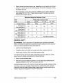
Product Manual
Router Table
Model No. 320. 28180
CAUTION! Read, understand
and
follow all Safety Rules and Operating
Instructions in this Manual before
using this product.
• Warranty
• Safety
• Assembly
° Operation
o Maintenance
Sears, Roebuck and Co., Hoffman Estates, IL 60179
www.craftsman.com
Warranty
Page 2
Safety Symbols
Page 3-4
Safety Instructions
Page 5-10
Know Your Router Table
Page 11-12
Unpacking
and Checking
Contents
Page 12
Parts list
Page 13
Assembly
Page 14-17
Operation
Page 17-21
Maintenance
Pages 22
Troubleshooting
Pages 22
ONE YEAR FULL WARRANTY ON CRAFTSMAN®
TOOL
If this Craftsman tool fails to give complete satisfaction within one year
from the date of purchase, return it to any Sears store or parts & repair
center or other Craftsman outlet in the United States for free repair (or
replacement, if repair proves impossible).
This warranty does not include expendable parts such as lamps,
batteries, bits, or blades.
This warranty applies for only 90 days from the date of purchase if this
product is ever used for commercial or rental purposes.
This warranty gives you specific legal rights, and you may also have other
rights, which vary from state to state.
Sears, Roebuck and Co., Hoffman Estates, IL 60179
_, WARNING: Some dust created by using power tools contains chemicals
known to the state of California to cause cancer and birth defects or other
reproductive
SAVE THESE
harm.
INSTRUCTIONS!
READ ALL INSTRUCTIONSI
28180 Manual Revlsed_07-0228
Page 2
The purpose of safety symbols is to attract your attention to possible dangers. The
safety symbols, and the explanations with them, deserve your careful attention and
understanding. The symbol warnings DO NOT, by themselves, eliminate any danger. The instructions and warnings they give are no substitutes for proper accidentprevention measures.
_,
WARNING=
BE SURE to read and understand
all safety alert symbols,
such
as "DANGER," "WARNING," and "CAUTION" BEFORE using this product. Failure
to follow all instructions may result in electric shock, fire, and/or serious personal
injury.
SYMBOL
MEANINGS
SAFETY ALERT SYMBOL= Indicates DANGER, WARNING, OR CAUTION.
May be used in conjunction
,_
with other symbols or pictographs.
DANGER= Failure to obey this safety warning WILL result in death or serious
injury to yourself or to others. Always follow the safety precautions to reduce the risk
of fire, electric shock and personal injury.
,_
WARNING:
Failure to obey this safety warning CAN result in death or serious
injury to yourself or to others. Always follow the safety precautions to reduce the risk
of fire, electric shock and personal injury.
,_
CAUTION"
Failure to obey this safety warning MAY result in personal injury
to yourself or others or property damage. Always follow the safety precautions to
reduce the risk of fire, electric shock and personal injury.
DAMAGE PREVENTION
AND INFORMATION
MESSAGES
These inform the user of important information and/or instructions that could lead
to equipment or other property damage if they are not followed. Each message is
preceded by the word "NOTE," as in the example below:
NOTE= Equipment
followed.
and/or property damage may result if these instructions
28180 ManuaLRevlsed_07-O228
are not
Page 3
Some of these following symbols may be used on this tool. Please study them and
learn their meaning, Proper interpretation of these symbols will allow you to operate
the tool better and more safely.
SYMBOL
NAME
DESIGNATION
/ EXPLANATION
V
Volts
Voltage
A
Amperes
Current
Hz
He rtz
W
Watt
Frequency (cycles per second)
Power
rnin
Minutes
Time
,-,,_,
Alternating
Current
Type of current
Direct Current
Type or a characteristic
no
No Load Speed
Rotational
[]
Class I1Construction
Double-insulated
_Jmin
Per Minute
Revolutions. strokes, surface speed.
orbits, etc.. per minute
@
Wet Cond tons Alert
Do not expose to rain or use in damp
locations,
Read the Product Manual
To reduce the risk of in ury, user must
read and understand product manua
before using this producL
Eye Protection
Always wear safety goggles or safety
glasses with side shields and a fuIFface
shield when operating this product.
Safety Alert
Precautions
No Hands Symbol
Failure to keep your hands away from
the blade will result in serious personal
injury.
No Hands Symbol
Failure to keep your hands away from
the blade will result in serious personal
injury.
No Hands Symbol
Failure to keep your hands away from
the blade will result in serious personal
injury.
No Hands Symbol
Failure to keep your hands away from
the blade will result in serious personal
injury
@
0
A
@
@
@
®
Hot Surface
28580 Manual Revised_07-0228
of current
speed, at no load
construction
that involve your safety,
To reduce the risk of injury or damage,
avoid contact with any hot surface,
Page 4
WARNING:
READ AND UNDERSTAND ALL INSTRUCTIONS.
Failure to fol-
low all instructions listed below and the instructions in the product manual for your
router may result in serious personal injury.
WORK AREA SAFETY
•
Keep the work area clean and well lit. Cluttered
invite accidents.
benches and dark areas
Don't use in a dangerous environment.
Don't use power tools in damp or
wet locations or expose them to rain. Don't operate power tools in potentially
explosive environments, such as in the presence of flammable liquids, gases,
or dust. Power tools create sparks, which may ignite the dust or fumes.
Operate the tool in well-ventilated
areas, and provide proper dust removal
Dust generated from some materials can be hazardous to your health. Use
dust-collection
systems whenever possible.
Keep children and bystanders
away. All visitors should be kept a safe distance away from the work area.
Use the right tool. Don't force a tool or attachment
was not designed.
Make the workshop
ing starter keys.
kid-proof
with padlocks,
to do a job for which it
master switches,
or by remov-
ELECTRICALSAFETY
Grounded
tools
In the event of a malfunction or breakdown, grounding provides a path of
least resistance for electric current to reduce the risk of electric shock, This
router table is equipped with an electrical cord having an equipment-grounding conductor and a grounding plug. The plug must be plugged into a matching outlet that is properly installed and grounded in accordance with all local
codes and ordinances°
Do not modify the plug provided. If it will not fit into the outlet, have the proper
outlet installed by a qualified electrician.
Improper connection of the equipment-grounding
conductor can result in a
risk of electric shock. The conductor with a green-colored outer insulation
cover, with or without yellow stripes, is the equipment-grounding
conductor, If
repair or replacement is necessary, do not connect the equipment-grounding
conductor to a live terminal,
=
Check with a qualified electrician or service personnel if the grounding instructions are not completely understood, or if in doubt as to whether the tool
is properly grounded.
28180 ManuaLRevised_07©228
Page 5
o
Use only 3-wire extension cords that have 3-prong
pole receptacles that accept the tool's plug.
o
Repair or replace a damaged
Repair or replace damaged
grounding
plugs and 3-
or worn cord immediately.
or worn cord immediately.
This tool is intended for use on a circuit that has an outlet that looks like the one
illustrated in Sketch A in the figure below. The tool has a grounding plug that
looks like the plug illustrated in sketch A in the figure below. A temporary adapter,
which looks like the adapter illustrated in Sketches B and C, may be used to
connect this plug to a 2-pole
receptacle as shown in Sketch
B if a properly grounded outlet
is not available. The tempoflil_
rary adapter should be used
Screw
only until a properly grounded
outlet can be installed by
Metal
\
a qualified electrician. The
Grounding Pin
green-colored rigid ear, lug,
Cover of Grounded
and the like, extending from
Outlet Box
the adapter must be connect(_
GrOolndieg Means
ed to a permanent ground,
such as a properly grounded
outlet box.
",, /
Double-insulated
The fixed-base
tools
router that is included with the router table is a double-insulated
Carefully read and understand
operating the tool
•
Replacement
all instructions
for the fixed-base
parts: When servicing use only identical
tool,
router before
replacement
parts.
Polarized plugs: To reduce the risk of electric shock, this equipment has a polarized plug (one blade is wider than the other). This plug will fit in a polarized
outlet only one way. If the plug does not fit fully in the outlet, reverse the plug.
If it still does not fit, contact a qualified electrician to install the proper outlet,
Do not change the plug in any way,
Use the proper
extension
cord,
•
Make sure that your extension
•
When using an extension cord, be sure to use one heavy enough to carry the
current your product will draw, An undersized cord will cause a drop in line
voltage resulting in loss of power and overheating.
28180 Manual Revised_0743228
cord is in good condition
Page 6
Table A shows the correct size to use, depending on cord length and ampere
rating. If in doubt, use the next heavier gauge: the smaller the gauge number,
the heavier the cord.
When operating a power tool outdoors, ALWAYS use an outdoor extension
cord marked "W-A" or "W." These cords are rated for outdoor use and reduce the risk of electric shock.
Minumum
Gauge for Extension Cords
Volts
Total Length of Cord in Feet
0-25ft.
25-50_.
51-100ff.
101-150_.
Ampere Rating
AWG
AWG
AWG
AWG
More than 0
Not more than 6
18
16
16
14
More than 6 i
Not more than 10
18
16
14
12
More than 10
Not more than 12
16
16
14
12
More than 12
Not more than 16
14
12
'120V
PERSONAL
Not Recommended
SAFETY
,_ WARNING: Use of this product can generate dust containing chemicals
known to the state of California to cause cancer, birth defects or other reproductive harm. Some examples of these chemicals are:
=
Lead from lead-based
o
Crystalline
•
Arsenic and chromium,
paints.
silica from bricks and cement and other masonry products.
from chemically
treated lumber.
Your risk from these exposures varies, depending upon how often you do this
type of work. To reduce your exposure to these chemicals:
•
Work in a well-ventilated
area.
•
Work with approved safety equipment, such as those dust masks that are
specially designed to filter out microscopic particles_
Avoid prolonged contact with dust from power sanding, sawing, grinding, drilling
and other construction activities, Wear protective clothing and wash exposed
areas with soap and water. Allowing dust to get into your mouth, eyes or lay on
the skin may promote absorption of harmful chemicals,
28180 ManuaLRevlsed_07-0228
Page7
,_
WARNING:
The operation of any power tool can result in foreign objects be-
ing thrown into your eyes, which can result in severe eye damage. Before beginning power-tool operation, always wear safety goggles or safety glasses with side
shields, and a full-face shield when needed. We recommend Wide Vision Safety
Mask for use over eyeglasses or standard safety glasses with shields. Always use
eye protection that is marked to comply with ANSI Z87.1
o
Stay alert, watch what you are doing, and use
common sense when operating a power tool. Do
not use the tool while tired or under the influence of
WEARYOUR
drugs, alcohol, or medication.
Wear proper apparel. Do not wear loose clothing,
gloves, neckties, rings, bracelets, or other jewelry
which may get caught in moving parts. Non-slip
footwear is recommended.Wear
protective hair covering to contain long hair.
o
Keep your hair, clothing, and gloves away from moving parts.
=
Remove adjusting keys and wrenches. Form a habit of checking to see that
keys and adjusting wrenches are removed from the tool before turning it on.
o
Always use safety glasses, Also use face or dust mask if cutting operation is
dusty. Everyday glasses may have impact-resistant
lenses, but they are NOT
safety glasses.
•
Never touch the pins of the electrical
ing it from an electrical socket.
o
Never stand on tool, Serious injury could occur if the tool is tipped, or if the
cutting tool is unintentionally contacted.
plug while inserting it into or remov-
TOOL USE AND CARE SAFETY
o
Use recommended
accessories.
Consult the owner's manual for recom-
mended accessories. The use of improper accessories
injury to persons.
may cause risk of
•
Keep guards in place and in working order.
•
Secure work. Use clamp or a vise to hold work when practical
using your hand and it frees both hands to operate tool.
•
Recuse the risk of unintentional starting. Be sure the switch is in the "OFF"
position before plugging the tool into an electrical outlet.
•
Do not use a tool if the switch does not turn it "ON" or "OFF". Any tool
that cannot be controlled with the switch is dangerous and must be repaired.
•
Do not carry tools with your finger on the switch.
•
Do not overreach.
28580 ManuaLRevised_07_0228
It is safer than
Keep proper footing and balance at all time&
Page8
O
Do not force the tool, Use the correct tool and blade for your application.
The correct tool and cutter will do the job better and more safely at the rate
for which it is designed.
o
Disconnect
tools before servicing; when changing
blades, bits, cutters, and the like.
o
Store idle tools out of the reach of children and other untrained people.
o
Never leave the tool running unattended;
the tool until it comes to a complete stop.
0
Always maintain tools with care, Keep cutting tools sharp and clean. Properly maintained tools with sharp cutting edges are less likely to bind and are
easier to control. Follow all instructions for lubricating and changing accessories.
o
Check for damaged parts. Before further use of the tool, a guard or other
part that is damaged should be carefully checked to determine that it will
operate properly and perform its intended function. Check for alignment of
moving parts, binding of moving parts, mounting, and any other conditions
that may affect its operationo A guard or other part that is damaged should be
properly repaired or replaced.
0
Direction of feed, Feed work into a blade or cutter against the direction
rotation of the blade or cutter only.
SERVICE
accessories,
such as
turn the power off_ Don't leave
of
SAFETY
=
Tool service MUST be performed only by qualified repair personnel. Service
or maintenance performed by an unqualified person could result in a risk of
injury
•
Use only identical replacement
•
Follow the instructions
parts when servicing
in the Maintenance
a power tool.
section of this Product Manual.
Use of unauthorized parts or failure to follow Maintenance
create a risk of electric shock or injury.
SPECIFIC
Instructions
may
SAFETY FOR THE ROUTER TABLE
=
Read and understand the router table and the instructions and warnings
in the product manuals for the router table and the router. Failure to follow
all instructions and warnings may result in serious personal injury_
@
Fully assemble and tighten all fasteners required for this table and for
mounting the router to the table. Do not use the router table until all assembly and installation steps have been completed. Before each use, check the
stand and the router to make sure that all fasteners are still tight. A loose
stand is unstable and may shift in use.
•
Unplug the router before installing it into the table, "['urn off the router-table
safety switch controlling power to the the router, or unplug the router before
making adjustments or changing accessories, such as bits or cutters.
28180 ManuaLRev_sed_07-0228
Page 9
Do not plug the router power cord into a wall outlet. It must be plugged
into the router table switch. Power tool switches and controls need to be
within your reach in emergency
situations°
Before operating, make sure that the entire unit (table with router installed)
is placed on and secured to a solid, flat, level surface and that it will not tip.
Use of auxiliary infeed and ouffeed supports is necessary for long or wide
work pieces. Long work pieces without adequate support can flip off the table
or cause the table to tip over.
Do not use the router table without the bit guard. Remove all dust, chips,
and any other foreign particles that can affect its function. Adjust the guard
height so that it clears the router bit and work piece. The guard will aid in
keeping hands from unintended contact with the rotating bit.
Never place your fingers
router is plugged in.
near a spinning bit or under the guard when the
Never hold the work piece on the ouffeed side of the bit. Pressing the
work piece against the out-feed side of the fence may cause the material to
bind, which may cause kickback and pull your hand back into the bit.
Guide the work piece against the fence to maintain control of the work
piece. Do not place material between the router bit and the fence while routing the edge. This placement will cause the material to become wedged,
possibly causing kickback.
Reuters are intended for working with wood, wood-like
plastic or laminates, not for cutting or shaping metals.
products, and
Be sure the work piece does not contain nails, etc. Cutting nails may
cause loss of control.
Do not use bits with cutting diameters that exceed the clearance hole in
the tabletop insert. The bit could contact the inset ring, throwing fragments.
o
Install the bit in accordance
with the instructions
in the router manual and
securely clamp the router bit in the collet chuck before making any cuts.
o
Never use dull or damaged bits. Sharp bits must be handled with care.
Damaged bits can snap during use. Dull bits require more force to push the
work piece, possibly causing the bit to break or the material to kickback.
The router table is designed to cut flat, straight, and squared material. Do
not cut material that is warped, wobbly, or otherwise unstable. If the material
is slightly curved, but otherwise stable, cut the material with the concave side
against the table or fence. Cutting the material with the concave side up or
away from the fence may cause the warped or wobbly material to roll and kick
back, causing the user to lose control.
Never start the tool when the bit is engaged in the material. The cutting
edge may grab the material, causing loss of control of the work piece.
28180 Manual_Revlsed_07-022S
Page10
Your router table has a precision-built electric switch box and it should be connected to only a 120-volt, 60-HZ AC power supply (normal household current),
DO NOT operate on direct current (DC). The large voltage drop would cause a
loss of power and the motor would overheat. If the router table does not operate when plugged into correct 120-volt, 60-HZ AC ONLY outlet, check the power
supply° The router table comes with an 8-ft. power cord (no adapter needed).
This Router Table has the following features:
50utfeed
fence
10, Dust Collection and Guard
pter
11 Above-the-table
3 Extended fence
1 Router table
2 Integrated safety
switch
8 Fastening
Back of the Switch
1,
Oversized table (14-1/8" x 23-5/8") for a large, smooth, durable, work surface and improved sound absorption. Table height clearance is 11-1/4 in. to
accommodate
most fixed and plunge-based routers
2_ Integrated safety switch with two outlets,
total capacity is 20 Amps.
Single-socket
capacity is t 5 Amps,
3.
Extended fence provides maximum work piece support; the fence can be
moved forward and backward 3-3/4 inch.
4.
Infeed
5.
Outfeed fence can be adjusted as much as 9/16-in. forward of the infeed
fence for joining operations.
&
Vacuum
7.
Miter-gauge
adjusts from 0° to 60 ° in both directions
many difficult feed situations.
8.
Fastening holes (11/32-inch
stable work surface.
28180 Manual
and outfeed
adapter
fence
can each be extended 2 in_
fits a 2-1/2 inch shop vacuum hose,,
Revised 0743228
for increased
stability in
dia.) allow the Router Table to be fixed to a
Page 11
9,
Integrated
switch shield prevents dust from accumulating
10. Dust Collection/Guard
in the sockets.
reduces dust dispersal,
11. Above-the-table
height adjustment: the bit height can be adjusted by turn..
ing the adjustment knob clockwise or counterclockwise
with a hex wrench (5
inches long and 5mm in diameter, not included). This feature functions only
when using the Craftsman router supplied with this table (model 17541) or the
following Craftsman routers: models 17542 and 17543.
_, WARNING:
If any parts are missing, DO NOT attempt to assemble, install,
or use your router table until the missing parts have been found or replaced and
your router table has been properly and correctly assembled according to this
product manual.
•
In order to simplify handling and to minimize any damage that may occur during shipping, your router table comes partially assembled.
*
Separate all parts from the packaging materials and check each part against
the illustration and the parts list on page 13 to make sure that all parts have
been included. Do this before discarding any of the packaging material.
28180 Manual_Revised_07-0228
Page12
Description
Key NO.
Quantity
1
Router table surface assembly
1
2
"Table leg
2
3
Fence assembly
1
4
Miter-gauge assembly
1
5
Clamping knob
3
6
Short, round-head,
7
Long pan-head screw
4
8
Short pan-head screw
4
9
Flat-head screw
3
10
Small nut
8
11
Plain washer
12
Small washer
16
13
Spring washers
8
Fig, 1
/
2
square-neck bolts
1
/
1
"
o-=_
Q
3
6
28180 Manual Revlsed 07-0228
7
8
9
10
11
12
la
Page13
ATTACHING
.
THE LEGS TO THE TABLE TOP
Place the router table
Fig, 2
surface upside down on
a flat, level surface, with
the underside of the table
facing up.
,
Position the legs relative to
the router table as shown
in Fig, 2.
Position one short end of
the table so that it extends
beyond the edge of your
work surface far enough
to gain access to the four
holes in that end of the
3_
router-table
,
.
top.
Align the two outermost
holes on the table top with
the holes in the leg bracket.
Place a flat washer (12) onto
each of two short, pan-head
screws (8),Insert the short,
pan-head screws up through
the holes in the table and
through the holes in the leg
brackeL Place a small washer
(12). a spring washer (13), and
small nut (10) on the threads
of the screw. Loosely tighten
the nuts. (Fig. 2)
,
Place a flat washer (12)
onto each of two long,
pan-head screws (7). Insert
the long, pan-head screws
up through the other two
holes on the table top
and through the corresponding
holes in the leg. Place a small washer (12), a
spring washer (13). and small nut (10) on the threads of the screw. (Fig. 3)
7.
Securely tighten all fasteners.
8.
Repeat with the other leg,
28180 ManuaLRevisad_074:)228
Page 14
ATTACHING THE ROUTER
TO THE TABLE
Fig. 4
Attach the router to the router
table after you have assembled the table.
Place the router table
upright, with the front edge
closest to you.
Be sure that the table is
stable and that it rests on
2_
all four legs,
.
Remove the sub-base
from the fixed-based
router supplied.
4_
5.
Hold the router upside down, and align the three holes in the center of the
table with the holes in the router, as shown in Fig° 4. Position the router so
that the screw holes used for attachment are not directly above either of the
router handles.
Insert a flat-head
router holes.
screw through each of the three router-table
holes into the
6_ Hold the router with one hand, and securely tighten each flat-head
with the other hand.
screw (9)
If you install a different router (one not supplied to the table), ensure that the diameter of the router sub-base does not exceed 6-7/8 inches. Six mounting holes
for the router are distributed in
Fig, 5
the center of the table; the distance between two opposite
6 71e"
holes is 5-3/8"o Select three
appropriate holes to mount the
router to the table. (Fig, 5)
The adjusting hole in the
table, shown in Fig. 5, is for
cutting height adjustment of
the router supplied (Model
No. 17541) or the following
Craftsman reuters: 17542 and
17543.
Adjusting Hole
28180 ManuaLRevlsed_07-0228
Page 15
ATTACHING THE FENCE TO
THE TABLE (Fig. 6)
Fig. 6
,_ WARNING" Always
unplug the router before attaching or removing the fence°
The fence has been shipped
completely assembled.
1. Place the fence assembly
on the table with the four
wing nuts facing toward you.
=
Align the two holes on the
bottom of fence assembly
with the two channels on
the router table.
Secure the fence to the
3_
Fig. 7
table with two clamping
knobs (5), two plain washers
(11), and two short, roundhead, square-neck bolts (6).
TO ATTACH THE MITER
GAUGE (Fig. 7)
The miter gauge has been
shipped completely assembled.
Attach the miter gauge to the
table by placing the miter-gauge
bar in the slot on the table.
MOUNTING THE TABLE TO
A WORK SURFACE (See Fig. 8)
1.
.
3.
Fig. 8
Place the router table, upright, on a sturdy surface,
e.g., work stand, workbench, or counter top.
While holding the router
table in place, mark on the
work surface the location
of the two mounting holes
(11/32-in diao) in each of
the legs.
Remove the router table.
28180 ManuaLRevlsed_07_9228
Page 16
=
5.
.
Drill a hole at each of the marked locations.
Place the router table on the work surface,
legs with the holes in the work surface.
and align the holes in the table
Secure the router table to the work surface
using four screws (not supplied).
7_ Securely tighten the screws°
SWITCH
OPERATION
The switch has a safety key to help prevent accidentally switching
and the unauthorized, possibly hazardous use by others°
The safety key must be completely
can be turned ON.
inserted
the router ON
into the switch before the switch
To operate the switch:
1.
Insert the safety key into
the switch. (Fig. 9)
2.
To turn the router ON,
pull out the ON/OFF
switch. (Fig. 10)
Safety Key
Fig. 10
28180 Manual_Revised_07<)228
Page17
3. To turn the router OFF,
push the ON/OFF switch
down. (Fig, 11)
Fig. 11
WARNING:
Never leave
the router unattended while it
is running or before it comes
to a complete stop.
,
To lock switch
in the OFF
position, push the ON/
OFF switch down to turn
the switch OFF, and remove the safety key from
the switch.
Two receptacles are located at the back of the switch assembly (Fig. 12). Use one
for plugging in the router. The other may be used to plug in a vacuum or a light
(not included). Two dust shields are designed to protect the receptacles.
,_ WARNING:
To ensure safety and reliability, when one receptacle in use, its
current draw must be less than 15 Amps; when two receptacles are used, the
total current of the two units must be less than 20 Amps.
NOTE: The vacuum adapter in the fence assembly is 2-1/2 in. in diameter; select
the vacuum accordingly.
Fig. 12
Dust Shield
28/80 ManuatRevised_07-0228
Page/8
ADJUSTING
THE FENCE
Fig_ 13
The fence enables you to support and guide the work piece,.
To adjust the extended fence
forward and backward (Fig, 13)
1.
Loosen the two clamping
knobs (5).
2.
Move the fence forward or
backward along the slots
to the desired position,
3,
Tighten the clamping
knobs.The fence can be
moved forward and backward 3-3/4 in.
Fig, 'I 4
To laterally adjust the
infeed and ouffeed fence
The infeed and outfeed fence
can each be adjusted 2 inches
in order to lengthen the fence°
1.
Loosen the four wing nut&
2.
Move the fence facings
right or left to the desired
position. (Fig° 14)
3.
Tighten the wing nuts.
To adjust the outfeed fence
for joining (Fig. 15)
For joining operations, the
outfeed fence can be adjusted
as much as 9/16-inch forward
of the infeed fence to support
the work piece after it passes
across the router bit.
°
Loosen the two outfeed
fence clamping
2_
3_
Fig. 15
knobs.
Move the outfeed fence
forward of the infeed fence
to the width of material
you want to remove from
the work piece. Tighten
the clamping knobs.
Move and clamp the entire extended fence so that the outfeed fence is aligned
with the cutting edge of the bit.
28180 ManuaLRevised
07.0228
Page 19
ADJUSTING
THE MITER GAUGE (Fig. 16)
1,
Loosen the miter gauge knob,
2,
Rotate the miter gauge to the desired angle.
3,
Tighten the miter
gauge knob.
Fig. 16
ADJUSTING
THE
CUTTING HEIGHT
NOTE: This method of cutting
height adjustment is applicable only to the fixed-base
router supplied with this router
table or other Craftsman routers with the following model
numbers: 17542 and 17543.
NOTE." A hex wrench 5 inches
long and 5mm in diameter
is required for this operation
(not included).
The cutting height can be
adjusted
by turning the Fine
Adjustment
Dial clockwise
or counterclockwise
with a
hex wrench.
Fig. 17
Adjusting Hole
NOTE: Be sure the worm gear
system in the router is engaged before making adjustments. Test it by turning the
Adjustment Dial on the router
clockwise and counter-clockwise to see if the bit lowers
and raises. If it does not, press in the router Coarse Adjustment
the Fine Adjustment Dial until the gears engage,
.
Knob and turn
Turn off the table switch by pushing down on the ON/OFF switch.
2_ Loosen the clamping
lever on the route_
3_ Insert the hex wrench into the adjusting hole on the table top (Fig. 17), and
turn the router adjustment dial clockwise with the hex wrench to move the
router collet down or counterclockwise
to move the collet up.
4,
When the desired cutting height is set, tighten the clamping
28180 ManuaLRevised_07-0228
lever on the router.
Page 20
USING THE ROUTER WITH THE ROUTER TABLE
1.
Read the and understand
entire Product Manual for the router,
2.
Always plug the router into the switched outlet in the router table° Never plug
a router-table-mounted
router into another power source.
3.
Make sure the router-table
4.
Plug the router-table
switch is off. Lock-on the router switch.
cord into a power source°
5_ Turn on the power to the router table by pulling out the ON/OFF switch.
6.
Always control the power to the router with the router-table
the router is mounted
ROUTING
switch whenever
on the table.
OPERATION
1.
Read the and understand
entire Product Manual for the router.
2.
Adjust the fence to support the work piece to be cut.
NOTE: The work piece must always be held tight against the fence.
3.
Reconfirm that all router adjustments
power to the router,
4.
Feed the work piece from right to left.
WARNING"
The direction
are securely locked before supplying
of feed for the work piece is always against the
sharp edges of the cutter and into the rotation of the cutter. Failure to follow this
rule can result in serious personal injury.
28180 Manual_Revised_07-0228
Page21
GENERAL
,_
MAINTENANCE
WARNING"
Avoid using solvents when cleaning plastic parts. Most plastics
are susceptible to damage from various types of commercial solvents and may
be damaged by their use. Use clean cloths to remove dirt, dust, oil, grease, etc.
,_
WARNING;
Do not at any time let brake fluids, gasoline, petroleum-based
products, penetrating oils, etc., come in contact with plastic parts. Chemicals can
damage, weaken or destroy plastic, which may result in serious personal injury.
WARNING"
Always wear safety goggles or safety glasses with side shields
during power-tool operation
wear a dust mask.
PROBLEM
or when blowing dust. If the operation
CAUSE
The router is not plugged
into the table outlet.
The router does not
work
The table surface is
not flat
The router can not
be attached to the
table
The router-table cord is
not connected to a power
source
is dusty, also
SOLUTION
Insert router power cord
plug into a table outlet
Plug the router-table cord
into a power source
The Router switch is in
"OFF" position,
Insert key and pull the
switch to the ON position
Legs are not properly assembled,
Check assembly directions
and securely tighten all
fasteners
Work surface is not flat.
Place router table on a flat,
level surface
Sub-base is too large
28:$80 Manual_Revlsed_07-O228
Use a sub-base 6-7/8 in. in
diameter or less.
Page 22
28180
Manual_Revlsed_07-0228
Page
23
Get it fixed, at your home or ours!
i
¸
Your Home
For repair- in your home - of all major brand appliances
lawn and garden equipment or heating and cooling systems
no matter who made it, no matter who sold it!
For the replacement parts, accessories and
owner's manuals that you need to do-it-yourself
For Sears professional installation of home appliances
and items like garage door openers and water heaters.
1-800-4-MY-HOME
®
(I-800-469-4663)
www.sears.com
Call anytime, day or night
(U S A and Canada)
www_sears,ca
For expert home solutions advice www.managemyhome.com
i
i!
/!
Our Home
For repair of carry-in products like vacuums, lawn equipment,
and electronics, call or go on-line for the nearest
Sears Parts & Repair Service Center
1-800-488-1222
(u SA )
1-800-469-4663 (Canada)
Call anytime, day or night
www.sears.com
www.sears.ca
To purchase a protection agreement on a product serviced by Sears:
1-800-827-6655
(u.s_,.)
Para pedir servicio de reparaciSn
a domicilio, y para ordenar plezas.
1-888-SU-HOGAR®
(1-888-784-6427)
i_i_
1-800-361-6665
(Canada)
Au Canada pour service en franr,.ais
1-800-LE-FOYER Mc
(1-800-533-8937)
www.sears.ca
,
© SearsBrands,LLC
® Registered Trademark / TM Trademark / SM Service Mark of Sears Brands, LLC
® Marca Registrada / TM Marca de F&brica / SM Marca de Servicio de Sears Brands, LLC
_c Marque de commerce / MDMarque d_pos_e de Sears Brands, LLC