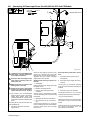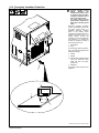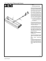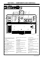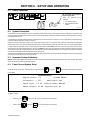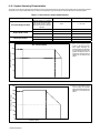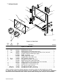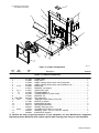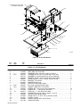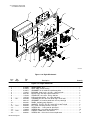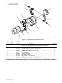
1
OM-222 166W 2011−11 Processes Induction Heating Description Induction Heating Power Source ProHeat 35 [ CE And Non CE Models Visit our website at www.MillerWelds.com File: Induction Heating From Miller to You Thank you and congratulations on choosing Miller. Now you can get the job done and get it done right. We know you don’t have time to do it any other way. That’s why when Niels Miller first started building arc welders in 1929, he made sure his products offered long-lasting value and superior quality. Like you, his customers couldn’t afford anything less. Miller products had to be more than the best they could be. They had to be the best you could buy. Today, the people that build and sell Miller products continue the tradition. They’re just as committed to providing equipment and service that meets the high standards of quality and value established in 1929. This Owner’s Manual is designed to help you get the most out of your Miller products. Please take time to read the Safety precautions. They will help you protect yourself against potential hazards on the worksite. We’ve made installation and operation quick and easy. With Miller you can count on years of reliable service with proper maintenance. And if for some reason the unit needs repair, there’s a Troubleshooting section that will help you figure out what the problem is. The Miller is the first welding parts list will then help you to decide the equipment manufacturer in exact part you may need to fix the problem. the U.S.A. to be registered to the ISO 9001 Quality System Warranty and service information for your Standard. particular model are also provided. Miller Electric manufactures a full line of welders and welding related equipment. For information on other quality Miller products, contact your local Miller distributor to receive the latest full line catalog or individual specification sheets. To locate your nearest distributor or service agency call 1-800-4-A-Miller, or visit us at www.MillerWelds.com on the web. Mil_Thank 2009−09 Working as hard as you do − every power source from Miller is backed by the most hassle-free warranty in the business. TABLE OF CONTENTS SECTION 1 − SAFETY PRECAUTIONS − READ BEFORE USING . . . . . . . . . . . . . . . . . . . . . . . . . . . . . . . . . 1-1. Symbol Usage . . . . . . . . . . . . . . . . . . . . . . . . . . . . . . . . . . . . . . . . . . . . . . . . . . . . . . . . . . . . . . . . . . . . . . . 1-2. Induction Heating Hazards . . . . . . . . . . . . . . . . . . . . . . . . . . . . . . . . . . . . . . . . . . . . . . . . . . . . . . . . . . . . . 1-3. Additional Symbols for Installation, Operation, and Maintenance . . . . . . . . . . . . . . . . . . . . . . . . . . . . . . 1-4. California Proposition 65 Warnings . . . . . . . . . . . . . . . . . . . . . . . . . . . . . . . . . . . . . . . . . . . . . . . . . . . . . . 1-5. Principal Safety Standards . . . . . . . . . . . . . . . . . . . . . . . . . . . . . . . . . . . . . . . . . . . . . . . . . . . . . . . . . . . . . 1-6. EMF Information . . . . . . . . . . . . . . . . . . . . . . . . . . . . . . . . . . . . . . . . . . . . . . . . . . . . . . . . . . . . . . . . . . . . . SECTION 2 − CONSIGNES DE SÉCURITÉ − LIRE AVANT UTILISATION . . . . . . . . . . . . . . . . . . . . . . . . . . 2-1. Signification des symboles . . . . . . . . . . . . . . . . . . . . . . . . . . . . . . . . . . . . . . . . . . . . . . . . . . . . . . . . . . . . . 2-2. Dangers relatifs au soudage à l’arc . . . . . . . . . . . . . . . . . . . . . . . . . . . . . . . . . . . . . . . . . . . . . . . . . . . . . . 2-3. Dangers supplémentaires en relation avec l’installation, le fonctionnement et la maintenance . . . . . 2-4. Proposition californienne 65 Avertissements . . . . . . . . . . . . . . . . . . . . . . . . . . . . . . . . . . . . . . . . . . . . . . 2-5. Principales normes de sécurité . . . . . . . . . . . . . . . . . . . . . . . . . . . . . . . . . . . . . . . . . . . . . . . . . . . . . . . . . 1 1 1 2 3 3 3 4 4 4 5 6 6 2-6. Informations relatives aux CEM . . . . . . . . . . . . . . . . . . . . . . . . . . . . . . . . . . . . . . . . . . . . . . . . . . . . . . . . . SECTION 3 − DEFINITIONS . . . . . . . . . . . . . . . . . . . . . . . . . . . . . . . . . . . . . . . . . . . . . . . . . . . . . . . . . . . . . . . . . . 3-1. Warning Label Definitions . . . . . . . . . . . . . . . . . . . . . . . . . . . . . . . . . . . . . . . . . . . . . . . . . . . . . . . . . . . . . . 3-2. Warning Label Definitions (Continued) . . . . . . . . . . . . . . . . . . . . . . . . . . . . . . . . . . . . . . . . . . . . . . . . . . . 3-3. WEEE Label (For Products Sold Within The EU) . . . . . . . . . . . . . . . . . . . . . . . . . . . . . . . . . . . . . . . . . . 3-4. Symbols And Definitions . . . . . . . . . . . . . . . . . . . . . . . . . . . . . . . . . . . . . . . . . . . . . . . . . . . . . . . . . . . . . . . SECTION 4 − INSTALLATION . . . . . . . . . . . . . . . . . . . . . . . . . . . . . . . . . . . . . . . . . . . . . . . . . . . . . . . . . . . . . . . . 4-1. Important Information Regarding CE Products (Sold Within The EU) . . . . . . . . . . . . . . . . . . . . . . . . . . 4-2. Serial Number and Rating Label Location . . . . . . . . . . . . . . . . . . . . . . . . . . . . . . . . . . . . . . . . . . . . . . . . . 4-3. Specifications . . . . . . . . . . . . . . . . . . . . . . . . . . . . . . . . . . . . . . . . . . . . . . . . . . . . . . . . . . . . . . . . . . . . . . . . 4-4. Selecting A Location . . . . . . . . . . . . . . . . . . . . . . . . . . . . . . . . . . . . . . . . . . . . . . . . . . . . . . . . . . . . . . . . . . 4-5. Tipping . . . . . . . . . . . . . . . . . . . . . . . . . . . . . . . . . . . . . . . . . . . . . . . . . . . . . . . . . . . . . . . . . . . . . . . . . . . . . 4-6. Electrical Service Guide . . . . . . . . . . . . . . . . . . . . . . . . . . . . . . . . . . . . . . . . . . . . . . . . . . . . . . . . . . . . . . . 4-7. Connecting 3-Phase Input Power For 460/575 Volt Models . . . . . . . . . . . . . . . . . . . . . . . . . . . . . . . . . . 4-8. Connecting 3-Phase Input Power For 400/460 Volt IEC And CE Models . . . . . . . . . . . . . . . . . . . . . . . 4-9. Power Source Output Connections . . . . . . . . . . . . . . . . . . . . . . . . . . . . . . . . . . . . . . . . . . . . . . . . . . . . . . 4-10. Remote 14 Receptacle RC14 Information and Connections . . . . . . . . . . . . . . . . . . . . . . . . . . . . . . . . . 4-11. Remote 14 Socket Information . . . . . . . . . . . . . . . . . . . . . . . . . . . . . . . . . . . . . . . . . . . . . . . . . . . . . . . . . . 4-12. Temperature Recorder Receptacle RC9 Information And Connections . . . . . . . . . . . . . . . . . . . . . . . . 4-13. Temperature Recorder Socket Information . . . . . . . . . . . . . . . . . . . . . . . . . . . . . . . . . . . . . . . . . . . . . . . . 4-14. Secondary Insulation Protection . . . . . . . . . . . . . . . . . . . . . . . . . . . . . . . . . . . . . . . . . . . . . . . . . . . . . . . . 4-15. 115 Volt AC Duplex Receptacle And Supplementary Protector . . . . . . . . . . . . . . . . . . . . . . . . . . . . . . . 4-16. Locating Thermocouples . . . . . . . . . . . . . . . . . . . . . . . . . . . . . . . . . . . . . . . . . . . . . . . . . . . . . . . . . . . . . . 4-17. Attaching Welded Thermocouples . . . . . . . . . . . . . . . . . . . . . . . . . . . . . . . . . . . . . . . . . . . . . . . . . . . . . . . 4-18. Using Contact Thermocouple Sensors . . . . . . . . . . . . . . . . . . . . . . . . . . . . . . . . . . . . . . . . . . . . . . . . . . . SECTION 5 − COMPONENTS AND CONTROLS . . . . . . . . . . . . . . . . . . . . . . . . . . . . . . . . . . . . . . . . . . . . . . . . 5-1. Controls . . . . . . . . . . . . . . . . . . . . . . . . . . . . . . . . . . . . . . . . . . . . . . . . . . . . . . . . . . . . . . . . . . . . . . . . . . . . SECTION 6 − SETUP AND OPERATION . . . . . . . . . . . . . . . . . . . . . . . . . . . . . . . . . . . . . . . . . . . . . . . . . . . . . . . 6-1. Safety Equipment . . . . . . . . . . . . . . . . . . . . . . . . . . . . . . . . . . . . . . . . . . . . . . . . . . . . . . . . . . . . . . . . . . . . 6-2. System Description . . . . . . . . . . . . . . . . . . . . . . . . . . . . . . . . . . . . . . . . . . . . . . . . . . . . . . . . . . . . . . . . . . . 6-3. Important System Guidelines . . . . . . . . . . . . . . . . . . . . . . . . . . . . . . . . . . . . . . . . . . . . . . . . . . . . . . . . . . . 6-4. Power Source/System Setup . . . . . . . . . . . . . . . . . . . . . . . . . . . . . . . . . . . . . . . . . . . . . . . . . . . . . . . . . . . 6-4-1.Factory Defaults . . . . . . . . . . . . . . . . . . . . . . . . . . . . . . . . . . . . . . . . . . . . . . . . . . . . . . . . . . . . . . . . . . . 6-5. Programming . . . . . . . . . . . . . . . . . . . . . . . . . . . . . . . . . . . . . . . . . . . . . . . . . . . . . . . . . . . . . . . . . . . . . . . . 7 9 9 10 11 11 12 12 12 12 13 14 14 15 16 17 18 18 19 19 20 21 21 23 24 25 25 26 26 26 26 26 28 28 TABLE OF CONTENTS SECTION 6 − SETUP AND OPERATION (Continued) . . . . . . . . . . . . . . . . . . . . . . . . . . . . . . . . . . . . . . . . . . . 6-5-1.Temperature-Based Control . . . . . . . . . . . . . . . . . . . . . . . . . . . . . . . . . . . . . . . . . . . . . . . . . . . . . . . . . . 6-5-1-1. Preheat . . . . . . . . . . . . . . . . . . . . . . . . . . . . . . . . . . . . . . . . . . . . . . . . . . . . . . . . . . . . . . . . . . . . . 6-5-1-2. Bake-Out . . . . . . . . . . . . . . . . . . . . . . . . . . . . . . . . . . . . . . . . . . . . . . . . . . . . . . . . . . . . . . . . . . . . 6-5-1-3. PWHT (Post-Weld Heat Treat) . . . . . . . . . . . . . . . . . . . . . . . . . . . . . . . . . . . . . . . . . . . . . . . . . . 6-5-1-4. Custom Program . . . . . . . . . . . . . . . . . . . . . . . . . . . . . . . . . . . . . . . . . . . . . . . . . . . . . . . . . . . . . 6-5-2.Manual Control . . . . . . . . . . . . . . . . . . . . . . . . . . . . . . . . . . . . . . . . . . . . . . . . . . . . . . . . . . . . . . . . . . . . 6-5-3.Remote Control . . . . . . . . . . . . . . . . . . . . . . . . . . . . . . . . . . . . . . . . . . . . . . . . . . . . . . . . . . . . . . . . . . . . 6-5-4.Power vs Time Control . . . . . . . . . . . . . . . . . . . . . . . . . . . . . . . . . . . . . . . . . . . . . . . . . . . . . . . . . . . . . . 6-6. Run Status . . . . . . . . . . . . . . . . . . . . . . . . . . . . . . . . . . . . . . . . . . . . . . . . . . . . . . . . . . . . . . . . . . . . . . . . . . 6-6-1.Temperature Based Control . . . . . . . . . . . . . . . . . . . . . . . . . . . . . . . . . . . . . . . . . . . . . . . . . . . . . . . . . . 6-6-1-1. Preheat, Bake-Out And PWHT Run Status Screen . . . . . . . . . . . . . . . . . . . . . . . . . . . . . . . . . 6-6-1-2. Custom Program . . . . . . . . . . . . . . . . . . . . . . . . . . . . . . . . . . . . . . . . . . . . . . . . . . . . . . . . . . . . . 6-6-2.Manual Control . . . . . . . . . . . . . . . . . . . . . . . . . . . . . . . . . . . . . . . . . . . . . . . . . . . . . . . . . . . . . . . . . . . . 6-6-3.Remote Control . . . . . . . . . . . . . . . . . . . . . . . . . . . . . . . . . . . . . . . . . . . . . . . . . . . . . . . . . . . . . . . . . . . . 6-6-4.Power vs Time Control . . . . . . . . . . . . . . . . . . . . . . . . . . . . . . . . . . . . . . . . . . . . . . . . . . . . . . . . . . . . . . 6-7. Parameters . . . . . . . . . . . . . . . . . . . . . . . . . . . . . . . . . . . . . . . . . . . . . . . . . . . . . . . . . . . . . . . . . . . . . . . . . . 6-8. Cooler . . . . . . . . . . . . . . . . . . . . . . . . . . . . . . . . . . . . . . . . . . . . . . . . . . . . . . . . . . . . . . . . . . . . . . . . . . . . . . 6-9. Real-Time Operation . . . . . . . . . . . . . . . . . . . . . . . . . . . . . . . . . . . . . . . . . . . . . . . . . . . . . . . . . . . . . . . . . . 6-10. System Operating Characteristics . . . . . . . . . . . . . . . . . . . . . . . . . . . . . . . . . . . . . . . . . . . . . . . . . . . . . . . SECTION 7 − MAINTENANCE . . . . . . . . . . . . . . . . . . . . . . . . . . . . . . . . . . . . . . . . . . . . . . . . . . . . . . . . . . . . . . . . 7-1. Routine Maintenance . . . . . . . . . . . . . . . . . . . . . . . . . . . . . . . . . . . . . . . . . . . . . . . . . . . . . . . . . . . . . . . . . 7-2. Calibration Verification Equipment . . . . . . . . . . . . . . . . . . . . . . . . . . . . . . . . . . . . . . . . . . . . . . . . . . . . . . . 7-3. Calibration Verification Procedure . . . . . . . . . . . . . . . . . . . . . . . . . . . . . . . . . . . . . . . . . . . . . . . . . . . . . . . 7-3-1.Initial Set Up . . . . . . . . . . . . . . . . . . . . . . . . . . . . . . . . . . . . . . . . . . . . . . . . . . . . . . . . . . . . . . . . . . . . . . 7-3-2.TC Input/Output Check . . . . . . . . . . . . . . . . . . . . . . . . . . . . . . . . . . . . . . . . . . . . . . . . . . . . . . . . . . . . . 7-3-3.Finishing Procedure . . . . . . . . . . . . . . . . . . . . . . . . . . . . . . . . . . . . . . . . . . . . . . . . . . . . . . . . . . . . . . . . SECTION 8 − SAFETY PRECAUTIONS FOR SERVICING . . . . . . . . . . . . . . . . . . . . . . . . . . . . . . . . . . . . . . . . 8-1. Symbol Usage . . . . . . . . . . . . . . . . . . . . . . . . . . . . . . . . . . . . . . . . . . . . . . . . . . . . . . . . . . . . . . . . . . . . . . . 8-2. Servicing Hazards . . . . . . . . . . . . . . . . . . . . . . . . . . . . . . . . . . . . . . . . . . . . . . . . . . . . . . . . . . . . . . . . . . . . 8-3. California Proposition 65 Warnings . . . . . . . . . . . . . . . . . . . . . . . . . . . . . . . . . . . . . . . . . . . . . . . . . . . . . . 8-4. EMF Information . . . . . . . . . . . . . . . . . . . . . . . . . . . . . . . . . . . . . . . . . . . . . . . . . . . . . . . . . . . . . . . . . . . . . SECTION 9 − DIAGNOSTICS & TROUBLESHOOTING . . . . . . . . . . . . . . . . . . . . . . . . . . . . . . . . . . . . . . . . . . 9-1. Operator Interface Indicators . . . . . . . . . . . . . . . . . . . . . . . . . . . . . . . . . . . . . . . . . . . . . . . . . . . . . . . . . . . 9-2. Limit Conditions . . . . . . . . . . . . . . . . . . . . . . . . . . . . . . . . . . . . . . . . . . . . . . . . . . . . . . . . . . . . . . . . . . . . . . 9-3. Limit Condition Codes . . . . . . . . . . . . . . . . . . . . . . . . . . . . . . . . . . . . . . . . . . . . . . . . . . . . . . . . . . . . . . . . . 9-4. Fault Conditions . . . . . . . . . . . . . . . . . . . . . . . . . . . . . . . . . . . . . . . . . . . . . . . . . . . . . . . . . . . . . . . . . . . . . . 9-5. Fault Condition Codes . . . . . . . . . . . . . . . . . . . . . . . . . . . . . . . . . . . . . . . . . . . . . . . . . . . . . . . . . . . . . . . . . 9-6. System Diagnostic Screens . . . . . . . . . . . . . . . . . . . . . . . . . . . . . . . . . . . . . . . . . . . . . . . . . . . . . . . . . . . . 9-7. Removing Wrapper and Measuring Input Capacitor Voltage . . . . . . . . . . . . . . . . . . . . . . . . . . . . . . . . . 9-8. Blowing Out Inside Of Unit . . . . . . . . . . . . . . . . . . . . . . . . . . . . . . . . . . . . . . . . . . . . . . . . . . . . . . . . . . . . . SECTION 10 − ELECTRICAL DIAGRAM . . . . . . . . . . . . . . . . . . . . . . . . . . . . . . . . . . . . . . . . . . . . . . . . . . . . . . . SECTION 11 − PARTS LIST . . . . . . . . . . . . . . . . . . . . . . . . . . . . . . . . . . . . . . . . . . . . . . . . . . . . . . . . . . . . . . . . . . WARRANTY 26 28 28 29 29 30 34 34 34 35 35 35 35 36 36 36 36 37 37 40 41 41 42 42 42 42 42 46 46 46 47 47 48 48 49 49 50 50 51 53 54 56 58 DECLARATION OF CONFORMITY for European Community (CE marked) products. MILLER Electric Mfg. Co., 1635 Spencer Street, Appleton, WI 54914 U.S.A. declares that the product(s) identified in this declaration conform to the essential requirements and provisions of the stated Council Directive(s) and Standard(s). Product/Apparatus Identification: Product Stock Number PROHEAT 35 W/TEMPERATURE CONTROL 400460V, CE 907432 Council Directives: S S 2006/95/EC Low Voltage 2004/108/EC Electromagnetic Compatibility Standards: S S IEC 609741: 2005 Arc Welding Equipment – Welding Power Sources IEC 6097410:2007 Arc Welding Equipment Electromagnetic Compatibility Requirements Signatory: October 26, 2010 _____________________________________ David A. Werba MANAGER, PRODUCT DESIGN COMPLIANCE 240667C _________________________________________ Date of Declaration SECTION 1 − SAFETY PRECAUTIONS − READ BEFORE USING ihom _2011-10 Protect yourself and others from injury — read, follow, and save these important safety precautions and operating instructions. 1-1. Symbol Usage DANGER! − Indicates a hazardous situation which, if not avoided, will result in death or serious injury. The possible hazards are shown in the adjoining symbols or explained in the text. Indicates a hazardous situation which, if not avoided, could result in death or serious injury. The possible hazards are shown in the adjoining symbols or explained in the text. NOTICE − Indicates statements not related to personal injury. . Indicates special instructions. This group of symbols means Warning! Watch Out! ELECTRIC SHOCK, MOVING PARTS, and HOT PARTS hazards. Consult symbols and related instructions below for necessary actions to avoid the hazards. 1-2. Induction Heating Hazards The symbols shown below are used throughout this manual to call attention to and identify possible hazards. When you see the symbol, watch out, and follow the related instructions to avoid the hazard. The safety information given below is only a summary of the more complete safety information found in the Safety Standards listed in Section 1-5. Read and follow all Safety Standards. Only qualified persons should install, operate, maintain, and repair this unit. During operation, keep everybody, especially children, away. ELECTRIC SHOCK can kill. Touching live electrical parts can cause fatal shocks or severe burns. The power circuit and output bus bars or connections are electrically live whenever the output is on. The input power circuit and machine internal circuits are also live when power is on. Incorrectly installed or improperly grounded equipment is a hazard. D Do not touch live electrical parts. D Enclose any connecting bus bars and coolant fittings to prevent unintentional contact. Wear dry, hole-free insulating gloves and body protection. Insulate yourself from work and ground using dry insulating mats or covers big enough to prevent any physical contact with the work or ground. D D D Additional safety precautions are required when any of the following electrically hazardous conditions are present: in damp locations or while wearing wet clothing; on metal structures such as floors, gratings, or scaffolds; when in cramped positions such as sitting, kneeling, or lying; or when there is a high risk of unavoidable or accidental contact with the workpiece or ground. For these conditions, see ANSI Z49.1 listed in Safety Standards. And, do not work alone! D Disconnect input power before installing or servicing this equipment. Lockout/tagout input power according to OSHA 29 CFR 1910.147 (see Safety Standards). D Use only nonconductive coolant hoses with a minimum length of 18 inches (457 mm) to provide isolation. D Properly install, ground, and operate this equipment according to its Owner’s Manual and national, state, and local codes. D Always verify the supply ground − check and be sure that input power cord ground wire is properly connected to ground terminal in disconnect box or that cord plug is connected to a properly grounded receptacle outlet. D When making input connections, attach proper grounding conductor first − double-check connections. D Keep cords dry, free of oil and grease, and protected from hot metal and sparks. Frequently inspect input power cord for damage or bare wiring − replace cord immediately if damaged − bare wiring can kill. Turn off all equipment when not in use. Do not use worn, damaged, undersized, or poorly spliced cables. D D D D D D D D Do not drape cables over your body. Do not touch power circuit if you are in contact with the work, ground, or another power circuit from a different machine. Use only well-maintained equipment. Repair or replace damaged parts at once. Maintain unit according to manual. Wear a safety harness if working above floor level. Keep all panels and covers securely in place. SIGNIFICANT DC VOLTAGE exists in inverter power sources AFTER removal of input power. D Turn Off inverter, disconnect input power, and discharge input capacitors according to instructions in Maintenance Section before touching any internal parts. FUMES AND GASES can be hazardous. Induction Heating of certain materials, adhesives, and fluxes can produce fumes and gases. Breathing these fumes and gases can be hazardous to your health. D D D D D D D Keep your head out of the fumes. Do not breathe the fumes. If inside, ventilate the area and/or use local forced ventilation to remove fumes and gases. If ventilation is poor, wear an approved air-supplied respirator. Read and understand the Material Safety Data Sheets (MSDSs) and the manufacturer’s instruction for adhesives, fluxes, metals, consumables, coatings, cleaners, and degreasers. Work in a confined space only if it is well ventilated, or while wearing an air-supplied respirator. Always have a trained watchperson nearby. Fumes and gases from heating can displace air and lower the oxygen level causing injury or death. Be sure the breathing air is safe. Do not heat in locations near degreasing, cleaning, or spraying operations. The heat can react with vapors to form highly toxic and irritating gases. Do not overheat coated metals, such as galvanized, lead, or cadmium plated steel, unless the coating is removed from the heated area, the area is well ventilated, and while wearing an airsupplied respirator. The coatings and any metals containing these elements can give off toxic fumes if overheated. See coating MSDS for temperature information. OM-222 166 Page 1 FIRE OR EXPLOSION hazard. D D D D D INDUCTION HEATING can burn. D Do not overheat parts. D Watch for fire; keep extinguisher nearby. D Keep flammables away from work area. Do not locate unit on, over, or near combustible surfaces. Do not install unit near flammables. Do not operate where the atmosphere may contain flammable dust, gas, or liquid vapors (such as gasoline). After completion of work, inspect area to ensure it is free of sparks, glowing embers, and flames. D D D Do not touch hot parts bare-handed. D Allow cooling period before handling parts or equipment. D Do not touch or handle induction head/coil during operation. Keep metal jewelry and other metal personal items away from head/coil during operation. To handle hot parts, use proper tools and/or wear heavy, insulated welding gloves and clothing to prevent burns. Use only correct fuses or circuit breakers. Do not oversize or bypass them. 1-3. Additional Symbols for Installation, Operation, and Maintenance FALLING EQUIPMENT can injure. D Use handle and have person of adequate physical strength lift unit. D Move unit with hand cart or similar device. D For units without a handle, use equipment of adequate capacity to lift and support unit. D Keep equipment (cables and cords) away from moving vehicles when working from an aerial location. D If using lift forks to move unit, be sure forks are long enough to extend beyond opposite side of unit. D Follow the guidelines in the Applications Manual for the Revised NIOSH Lifting Equation (Publication No. 94−110) when manually lifting heavy parts or equipment. FLYING METAL OR DIRT can injure eyes. D Wear approved safety glasses with side shields or wear face shield. MOVING PARTS can injure. D Keep away from moving parts such as fans. D Keep all doors, panels, covers, and guards closed and securely in place. D Have only qualified persons remove doors, panels, covers, or guards for maintenance and troubleshooting as necessary. D Reinstall doors, panels, covers, or guards when maintenance is finished and before reconnecting input power. ELECTRIC AND MAGNETIC FIELDS (EMF) can affect Implanted Medical Devices. D Wearers of Pacemakers and other Implanted Medical Devices should keep away. D Implanted Medical Device wearers should consult their doctor and the device manufacturer before going near arc welding, spot welding, gouging, plasma arc cutting, or induction heating operations. OVERUSE can cause OVERHEATING D Allow cooling period. D Reduce output or reduce duty cycle before starting to heat again. D Follow rated duty cycle. OM-222 166 Page 2 STATIC (ESD) can damage PC boards. D Put on grounded wrist strap BEFORE handling boards or parts. D Use proper static-proof bags and boxes to store, move, or ship PC boards. H.F. RADIATION can cause interference. D High-frequency (H.F.) can interfere with radio navigation, safety services, computers, and communications equipment. D D D D D Have only qualified person familiar with electronic equipment perform this installation. The user is responsible for having a qualified electrician promptly correct any interference problem resulting from the installation. If notified by the FCC about interference, stop using the equipment at once. Have the installation regularly checked and maintained. Keep high-frequency source doors and panels tightly shut. READ INSTRUCTIONS. D Read and follow all labels and the Owner’s Manual carefully before installing, operating, or servicing unit. Read the safety information at the beginning of the manual and in each section. D Use only genuine replacement parts from the manufacturer. D Perform maintenance and service according to the Owner’s Manuals, industry standards, and national, state, and local codes. BATTERY EXPLOSION can injure. D Do not use induction equipment to charge batteries or jump start vehicles unless it has a battery charging feature designed for this purpose. 1-4. California Proposition 65 Warnings Welding or cutting equipment produces fumes or gases which contain chemicals known to the State of California to cause birth defects and, in some cases, cancer. (California Health & Safety Code Section 25249.5 et seq.) This product contains chemicals, including lead, known to the state of California to cause cancer, birth defects, or other reproductive harm. Wash hands after use. 1-5. Principal Safety Standards Safety in Welding, Cutting, and Allied Processes, ANSI Standard Z49.1, is available as a free download from the American Welding Society at http://www.aws.org or purchased from Global Engineering Documents (phone: 1-877-413-5184, website: www.global.ihs.com). Safety in Welding, Cutting, and Allied Processes, CSA Standard W117.2, from Canadian Standards Association, Standards Sales, 5060 Spectrum Way, Suite 100, Ontario, Canada L4W 5NS (phone: 800-463-6727, website: www.csa-international.org). OSHA, Occupational Safety and Health Standards for General Industry, Title 29, Code of Federal Regulations (CFR), Part 1910, Subpart Q, and Part 1926, Subpart J, from U.S. Government Printing Office, Superintendent of Documents, P.O. Box 371954, Pittsburgh, PA 15250-7954 (phone: 1-866-512-1800) (there are 10 OSHA Regional Offices—phone for Region 5, Chicago, is 312-353-2220, website: www.osha.gov). National Electrical Code, NFPA Standard 70, from National Fire Protection Association, Quincy, MA 02269 (phone: 1-800-344-3555, website: www.nfpa.org and www. sparky.org). Canadian Electrical Code Part 1, CSA Standard C22.1, from Canadian Standards Association, Standards Sales, 5060 Spectrum Way, Suite 100, Mississauga, Ontario, Canada L4W 5NS (phone: 800-463-6727, website: www.csa-international.org). Safe Practice For Occupational And Educational Eye And Face Protection, ANSI Standard Z87.1, from American National Standards Institute, 25 West 43rd Street, New York, NY 10036 (phone: 212-642-4900, website: www.ansi.org). Applications Manual for the Revised NIOSH Lifting Equation, The National Institute for Occupational Safety and Health (NIOSH), 1600 Clifton Rd, Atlanta, GA 30333 (phone: 1-800-232-4636, website: www.cdc.gov/ NIOSH). 1-6. EMF Information Electric current flowing through any conductor causes localized electric and magnetic fields (EMF). Welding current creates an EMF field around the welding circuit and welding equipment. EMF fields may interfere with some medical implants, e.g. pacemakers. Protective measures for persons wearing medical implants have to be taken. For example, restrict access for passers−by or conduct individual risk assessment for welders. All welders should use the following procedures in order to minimize exposure to EMF fields from the welding circuit: 4. Keep head and trunk as far away from the equipment in the welding circuit as possible. 1. Keep cables close together by twisting or taping them, or using a cable cover. About Implanted Medical Devices: Implanted Medical Device wearers should consult their doctor and the device manufacturer before performing or going near arc welding, spot welding, gouging, plasma arc cutting, or induction heating operations. If cleared by your doctor, then following the above procedures is recommended. 2. Do not place your body between welding cables. Arrange cables to one side and away from the operator. 3. Do not coil or drape cables around your body. 5. Connect work clamp to workpiece as close to the weld as possible. 6. Do not work next to, sit or lean on the welding power source. 7. Do not weld whilst carrying the welding power source or wire feeder. OM-222 166 Page 3 SECTION 2 − CONSIGNES DE SÉCURITÉ − LIRE AVANT UTILISATION ihom 2011−10_fre Pour écarter les risques de blessure pour vous−même et pour autrui — lire, appliquer et ranger en lieu sûr ces consignes relatives aux précautions de sécurité et au mode opératoire. 2-1. Signification des symboles DANGER! − Indique une situation dangereuse qui si on l’évite pas peut donner la mort ou des blessures graves. Les dangers possibles sont montrés par les symboles joints ou sont expliqués dans le texte. Indique une situation dangereuse qui si on l’évite pas peut donner la mort ou des blessures graves. Les dangers possibles sont montrés par les symboles joints ou sont expliqués dans le texte. NOTE − Indique des déclarations pas en relation avec des blessures personnelles. . Indique des instructions spécifiques. Ce groupe de symboles veut dire Avertissement! Attention! DANGER DE CHOC ELECTRIQUE, PIECES EN MOUVEMENT, et PIECES CHAUDES. Consulter les symboles et les instructions ci-dessous y afférant pour les actions nécessaires afin d’éviter le danger. 2-2. Dangers relatifs au soudage à l’arc Les symboles présentés ci-après sont utilisés tout au long du présent manuel pour attirer votre attention et identifier les risques de danger. Lorsque vous voyez un symbole, soyez vigilant et suivez les directives mentionnées afin d’éviter tout danger. Les consignes de sécurité présentées ci-après ne font que résumer l’information contenue dans les normes de sécurité énumérées à la section 2-5. Veuillez lire et respecter toutes ces normes de sécurité. D D D L’installation, l’utilisation, l’entretien et les réparations ne doivent être confiés qu’à des personnes qualifiées. D Au cours de l’utilisation, tenir toute personne à l’écart et plus particulièrement les enfants. D UNE DÉCHARGE ÉLECTRIQUE peut entraîner la mort. Le contact de composants électriques peut provoquer des accidents mortels ou des brûlures graves. Le circuit électrique et les barres collectrices ou les connexions de sortie sont sous tension lorsque l’appareil fonctionne. Le circuit d’alimentation et les circuits internes de la machine sont également sous tension lorsque l’alimentation est sur marche. Des équipements installés ou reliés à la borne de terre de manière incorrecte sont dangereux. D D D D D Installer le poste correctement et le mettre à la terre convenablement selon les consignes du manuel de l’opérateur et les normes nationales, provinciales et locales. Toujours vérifier la terre du cordon d’alimentation. Vérifier et s’assurer que le fil de terre du cordon d’alimentation est bien raccordé à la borne de terre du sectionneur ou que la fiche du cordon est raccordée à une prise correctement mise à la terre. En effectuant les raccordements d’entrée, fixer d’abord le conducteur de mise à la terre approprié et revérifier les connexions. Les câbles doivent être exempts d’humidité, d’huile et de graisse; protégez−les contre les étincelles et les pièces métalliques chaudes. Vérifier fréquemment le cordon d’alimentation afin de s’assurer qu’il n’est pas altéré ou à nu, le remplacer immédiatement s’il l’est. Un fil à nu peut entraîner la mort. L’équipement doit être hors tension lorsqu’il n’est pas utilisé. Ne pas utiliser des câbles usés, endommagés, de grosseur insuffisante ou mal épissés. Ne pas enrouler les câbles autour du corps. Ne pas toucher le circuit électrique si l’on est en contact avec la pièce, la terre ou le circuit électrique d’une autre machine. N’utiliser qu’un matériel en bon état. Réparer ou remplacer sur-lechamp les pièces endommagées. Entretenir l’appareil conformément à ce manuel. Porter un harnais de sécurité si l’on doit travailler au-dessus du sol. S’assurer que tous les panneaux et couvercles sont correctement en place. D D Ne pas toucher aux pièces électriques sous tension. Protéger toutes les barres collectrices et les raccords de refroidissement pour éviter de les toucher par inadvertance. D D D Porter des gants isolants et des vêtements de protection secs et sans trous. S’isoler de la pièce à couper et du sol en utilisant des housses ou des tapis assez grands afin d’éviter tout contact physique avec la pièce à couper ou le sol. Il reste une TENSION DC NON NÉGLIGEABLE dans les sources de soudage onduleur UNE FOIS le moteur coupé. D D D D D’autres consignes de sécurité sont nécessaires dans les conditions suivantes : risques électriques dans un environnement humide ou si l’on porte des vêtements mouillés ; sur des structures métalliques telles que sols, grilles ou échafaudages ; en position coincée comme assise, à genoux ou couchée ; ou s’il y a un risque élevé de contact inévitable ou accidentel avec la pièce à souder ou le sol. Dans ces conditions, voir ANSI Z49.1 énuméré dans les normes de sécurité. En outre, ne pas travailler seul ! Couper l’alimentation d’entrée avant d’installer l’appareil ou d’effectuer l’entretien. Verrouiller ou étiqueter la sortie d’alimentation selon la norme OSHA 29 CFR 1910.147(se reporter aux Principales normes de sécurité). N’utiliser que des tuyaux de refroidissement non conducteurs ayant une longueur minimale de 457 mm pour garantir l’isolation. D Avant de toucher des organes internes, couper l’onduleur, débrancher l’alimentation et décharger les condensateurs d’alimentation conformément aux instructions indiquées dans la partie maintenance. LES FUMÉES ET LES GAZ peuvent être dangereux. Le chauffage à induction de certains matériaux, adhésifs et flux génère des fumées et des gaz. Leur inhalation peut être dangereuse pour votre santé. D Ne pas mettre sa tête au-dessus des vapeurs. Ne pas respirer ces vapeurs. OM-222 166 Page 4 D À l’intérieur, ventiler la zone et/ou utiliser une ventilation forcée au niveau de l’arc pour l’évacuation des fumées et des gaz. D Si la ventilation est médiocre, porter un respirateur anti-vapeurs approuvé. Lire et comprendre les spécifications de sécurité des matériaux (MSDS) et les instructions du fabricant concernant les adhésifs, les flux, les métaux, les consommables, les revêtements, les nettoyants et les dégraisseurs. D D D D Travailler dans un espace fermé seulement s’il est bien ventilé ou en portant un respirateur. Demander toujours à un surveillant dûment formé de se tenir à proximité. Des fumées et des gaz provenant du chauffage peuvent déplacer l’air, abaisser le niveau d’oxygène et provoquer des lésions ou des accidents mortels. S’assurer que l’air ambiant ne présente aucun danger. Ne pas chauffer dans des endroits se trouvant à proximité d’opérations de dégraissage, de nettoyage ou de pulvérisation. La chaleur peut réagir en présence de vapeurs et former des gaz hautement toxiques et irritants. Ne pas surchauffer des métaux munis d’un revêtement tels que l’acier galvanisé, plaqué au plomb ou au cadmium, à moins que le revêtement ne soit enlevé de la zone chauffée, que la zone soit bien ventilée et, si nécessaire, en portant un respirateur. Les revêtements et tous les métaux contenant ces éléments peuvent dégager des fumées toxiques s’ils sont surchauffés. Voir les informations concernant la température dans les spécifications de revêtement MSDS. Risque D’INCENDIE OU D’EXPLOSION. D D D D D D Stocker des produits inflammables hors de la zone de travail. Ne pas placer l’appareil sur, au-dessus ou à proximité de surfaces inflammables. Ne pas installer l’appareil à proximité de produits inflammables. Ne pas faire fonctionner l’appareil si l’air ambiant est chargé de particules, gaz, ou vapeurs inflammables (vapeur d’essence, par exemple). Une fois le travail achevé, assurez−vous qu’il ne reste aucune trace d’étincelles incandescentes ni de flammes. Utiliser exclusivement des fusibles ou coupe−circuits appropriés. Ne pas augmenter leur puissance; ne pas les ponter. LE CHAUFFAGE PAR INDUCTION peut provoquer des brûlures. D Ne pas toucher des parties chaudes à mains nues. D Laisser refroidir les composants ou équipements avant de les manipuler. D Ne pas toucher ou manipuler la tête/l’enroulement à induction pendant le fonctionnement. D Tenir les bijoux et autres objets personnels en métal éloignés de la tête/de l’enroulement pendant le fonctionnement. Ne pas toucher aux pièces chaudes, utiliser les outils recommandés et porter des gants de soudage et des vêtements épais pour éviter les brûlures. D D Ne pas surchauffer les composants . D Attention aux risques d’incendie: tenir un extincteur à proximité. 2-3. Dangers supplémentaires en relation avec l’installation, le fonctionnement et la maintenance LA CHUTE DE L’ÉQUIPEMENT peut provoquer des blessures. D D D D D Utiliser la poignée et demander à une personne ayant la force physique nécessaire pour soulever l’appareil. D Déplacer l’appareil à l’aide d’un chariot ou d’un engin similaire. Pour les unités sans poignée, utiliser un équipement de levage de capacité suffisante pour lever l’appareil. Tenir l’équipement (câbles et cordons) à distance des véhicules mobiles lors de toute opération en hauteur. En utilisant des fourches de levage pour déplacer l’unité, s’assurer que les fourches sont suffisamment longues pour dépasser du côté opposé de l’appareil. Suivre les consignes du Manuel des applications pour l’équation de levage NIOSH révisée (Publication Nº94−110) lors du levage manuelle de pièces ou équipements lourds. DES ORGANES MOBILES peuvent provoquer des blessures. D S’abstenir de toucher des organes mobiles tels que des ventilateurs. D Maintenir fermés et verrouillés les portes, panneaux, recouvrements et dispositifs de protection. Les CHAMPS ÉLECTROMAGNÉTIQUES (CEM) peuvent affecter les implants médicaux. D Les porteurs de stimulateurs cardiaques et autres implants médicaux doivent rester à distance. D Les porteurs d’implants médicaux doivent consulter leur médecin et le fabricant du dispositif avant de s’approcher de la zone où se déroule du soudage à l’arc, du soudage par points, du gougeage, de la découpe plasma ou une opération de chauffage par induction. DES PIECES DE METAL ou DES SALETES peuvent provoquer des blessures dans les yeux. D Porter des lunettes de sécurité à coques latérales ou un écran facial. OM-222 166 Page 5 L’EMPLOI EXCESSIF peut CHAUFFER L’ÉQUIPEMENT. D SUR- D Prévoir une période de refroidissement D Réduire le courant de sortie ou le facteur de marche avant de recommencer le chauffage. Respecter le cycle opératoire nominal. LES CHARGES ÉLECTROSTATIQUES peuvent endommager les circuits imprimés. D Établir la connexion avec la barrette de terre AVANT de manipuler des cartes ou des pièces. D Utiliser des pochettes et des boîtes antistatiques pour stocker, déplacer ou expédier des cartes PC. D D L’utilisateur est tenu de faire corriger rapidement par un électricien qualifié les interférences résultant de l’installation. D Si le FCC signale des interférences, arrêter immédiatement l’appareil. Effectuer régulièrement le contrôle et l’entretien de l’installation. Maintenir soigneusement fermés les portes et les panneaux des sources de haute fréquence. D D LIRE LES INSTRUCTIONS. D Lire et appliquer les instructions sur les étiquettes et le Mode d’emploi avant l’installation, l’utilisation ou l’entretien de l’appareil. Lire les informations de sécurité au début du manuel et dans chaque section. D N’utiliser que les pièces de rechange recommandées par le constructeur. D Effectuer l’entretien en respectant les manuels d’utilisation, les normes industrielles et les codes nationaux, d’état et locaux. LE RAYONNEMENT HAUTE FRÉQUENCE (HF) risque de provoquer des interférences. L’EXPLOSION DE LA BATTERIE peut provoquer des blessures. D Le rayonnement haute fréquence (HF) peut provoquer des interférences avec les équipements de radio-navigation et de communication, les services de sécurité et les ordinateurs. D Ne pas utiliser l’appareil de soudage pour charger des batteries ou faire démarrer des véhicules à l’aide de câbles de démarrage, sauf si l’appareil dispose d’une fonctionnalité de charge de batterie destinée à cet usage. Demander seulement à des personnes qualifiées familiarisées avec des équipements électroniques de faire fonctionner l’installation. 2-4. Proposition californienne 65 Avertissements Les équipements de soudage et de coupage produisent des fumées et des gaz qui contiennent des produits chimiques dont l’État de Californie reconnaît qu’ils provoquent des malformations congénitales et, dans certains cas, des cancers. (Code de santé et de sécurité de Californie, chapitre 25249.5 et suivants). Ce produit contient des éléments chimiques, dont le plomb, reconnus par l’État de Californie pour leur caractère cancérogène ainsi que provoquant des malformations congénitales ou autres problèmes de procréation. Se laver les mains après toute manipulation. 2-5. Principales normes de sécurité Safety in Welding, Cutting, and Allied Processes, ANSI Standard Z49.1, from Global Engineering Documents (phone: 1-877-413-5184, website: www.global.ihs.com). Safety in Welding, Cutting, and Allied Processes, CSA Standard W117.2, from Canadian Standards Association, Standards Sales, 5060 Spectrum Way, Suite 100, Ontario, Canada L4W 5NS (phone: 800-463-6727, website: www.csa-international.org). OSHA, Occupational Safety and Health Standards for General Industry, Title 29, Code of Federal Regulations (CFR), Part 1910, Subpart Q, and Part 1926, Subpart J, from U.S. Government Printing Office, Superintendent of Documents, P.O. Box 371954, Pittsburgh, PA 15250-7954 (phone: 1-866-512-1800) (there are 10 OSHA Regional Offices—phone for Region 5, Chicago, is 312-353-2220, website: www.osha.gov). National Electrical Code, NFPA Standard 70, from National Fire Protection Association, Quincy, MA 02269 (phone: 1-800-344-3555, website: www.nfpa.org and www. sparky.org). Canadian Electrical Code Part 1, CSA Standard C22.1, from Canadian Standards Association, Standards Sales, 5060 Spectrum Way, Suite 100, Mississauga, Ontario, Canada L4W 5NS (phone: 800-463-6727, website: www.csa-international.org). Safe Practice For Occupational And Educational Eye And Face Protection, ANSI Standard Z87.1, from American National Standards Institute, 25 West 43rd Street, New York, NY 10036 (phone: 212-642-4900, website: www.ansi.org). Applications Manual for the Revised NIOSH Lifting Equation, The National Institute for Occupational Safety and Health (NIOSH), 1600 Clifton Rd, Atlanta, GA 30333 (phone: 1-800-232-4636, website: www.cdc.gov/ NIOSH). OM-222 166 Page 6 2-6. Informations relatives aux CEM Le courant électrique qui traverse tout conducteur génère des champs électromagnétiques (CEM) à certains endroits. Le courant de soudage crée un CEM autour du circuit et du matériel de soudage. Les CEM peuvent créer des interférences avec certains implants médicaux comme des stimulateurs cardiaques. Des mesures de protection pour les porteurs d’implants médicaux doivent être prises: Limiter par exemple tout accès aux passants ou procéder à une évaluation des risques individuels pour les soudeurs. Tous les soudeurs doivent appliquer les procédures suivantes pour minimiser l’exposition aux CEM provenant du circuit de soudage: 1. Rassembler les câbles en les torsadant ou en les attachant avec du ruban adhésif ou avec une housse. 2. Ne pas se tenir au milieu des câbles de soudage. Disposer les câbles d’un côté et à distance de l’opérateur. 3. Ne pas courber et ne pas entourer les câbles autour de votre corps. 4. Maintenir la tête et le torse aussi loin que possible du matériel du circuit de soudage. 5. Connecter la pince sur la pièce aussi près que possible de la soudure. 6. Ne pas travailler à proximité d’une source de soudage, ni s’asseoir ou se pencher dessus. 7. Ne pas souder tout en portant la source de soudage ou le dévidoir. En ce qui concerne les implants médicaux : Les porteurs d’implants doivent d’abord consulter leur médecin avant de s’approcher des opérations de soudage à l’arc, de soudage par points, de gougeage, du coupage plasma ou de chauffage par induction. Si le médecin approuve, il est recommandé de suivre les procédures précédentes. OM-222 166 Page 7 OM-222 166 Page 8 SECTION 3 − DEFINITIONS 3-1. Warning Label Definitions Warning! Watch Out! There are possible hazards as shown by the symbols. 1 1.1 1.2 2 2.1 2.2 3 3.1 3.2 4 4.1 4.2 4.3 5 5.1 6 7 Electric shock from wiring can kill. Wear dry insulating gloves. Do not wear wet or damaged gloves. Disconnect input plug or power before working on machine. Induction heating can cause injury or burns from hot items such as rings, watches, or parts. Do not wear metal jewelry and other metal personal items such as rings and watches during operation. Do not touch hot parts or hot head/coil. Induction heating sparks can cause fire. Do not overheat parts and adhesives. Keep flammables away from heating operation. Do not heat near flammables. Heating sparks can cause fires. Have a fire extinguisher nearby and have a watchperson ready to use it. Breathing heating fumes can be hazardous to your health. Read Material Safety Data Sheets (MSDSs) and manufacturer’s instructions for material used. Keep your head out of the fumes. Use forced ventilation or local exhaust to remove the fumes. Use ventilating fan to remove fumes. Always wear safety glasses or goggles during and around heating operations to prevent possible injury. Wear either safety glasses or full goggles depending on type of operation and nearby processes. Do not remove or paint over (cover) the label. Become trained and read the instructions before working on the machine or heating. 190 025 OM-222 166 Page 9 3-2. Warning Label Definitions (Continued) 1 2 1 3 2 3 4 5 6 5 4 7 Warning! Watch Out! There are possible hazards as shown by the symbols. Electric shock from wiring can kill. Overuse can cause overheating. Follow rated duty cycle. Disconnect input plug or power before working on machine. Become trained and read the instructions before working on the machine. Connect green or green/yellow grounding conductor to ground terminal. Connect input conductors (L1, L2 And L3) to line terminals. 6 7 194 466 1 2 1 2 3 4 3 4 Warning! Watch Out! There are possible hazards as shown by the symbols. Electric shock from wiring can kill. Disconnect input plug or power before working on machine. Do not touch input capacitor(s). Allow time for capacitor(s) to discharge. Check input capacitor(s) voltage (see Section 9-7). 227 085-A OM-222 166 Page 10 3-3. WEEE Label (For Products Sold Within The EU) Do not discard product (where applicable) with general waste. Reuse or recycle Waste Electrical and Electronic Equipment (WEEE) by disposing at a designated collection facility. Contact your local recycling office or your local distributor for further information. 3-4. Symbols And Definitions . Some symbols are found only on CE products. A IP Amperes Degree Of Protection V Hz Increase Volts Alternating Current Hertz Circuit Protection Line Connection I1 Primary Current X Duty Cycle Output I2 Rated Current U1 Primary Voltage U2 Load Voltage Read Instructions Three Phase Static Frequency Converter-Transformer-Frequency Converter I1max Rated Maximum Supply Current P1max Maximum Power Consumption Three Phase Percent Remote Panel/Local High Temperature Voltage Input Off On OM-222 166 Page 11 SECTION 4 − INSTALLATION 4-1. Important Information Regarding CE Products (Sold Within The EU) Information On Electromagnetic Compatibility (EMC) ! This Class A equipment is not intended for use in residential locations where the electrical power is provided by the public low− voltage supply system. There may be potential difficulties in ensuring electromagnetic compatibility in those locations, due to conducted as well as radiated disturbances. This equipment complies with IEC 61000−3−12 provided that the short−circuit power Ssc is greater than or equal to 8,911,817 at the interface point between the user’s supply and the public system. It is the responsibility of the installer or user of the equipment to ensure, by consultation with the distribution network operator if necessary, that the equipment is connected only to a supply with a short−circuit power Ssc greater than or equal to 8,911,817. 4-2. Serial Number and Rating Label Location The serial number and rating information for the power source is located on the front of the machine. Use the rating labels to determine input power requirements and/or rated output. For future reference, write serial number in space provided on back cover of this manual. 4-3. Specifications Output Frequen cy 5 To 30 kHz Rated Output Single Output Dual Output 35 kW At 100% Duty Cycle 350 A (RMS), 700 V (RMS) 35 kW At 100% Duty Cycle 700 A (RMS), 700 V (RMS) Required Reflective Inductance Amperes Input at Rated Load Output 50 or 60 Hz, Three-Phase 400 V 2.5 To 50 h 60 A Storage Temperature Range −40_ F (−40_ C) to 122_ F (50_ C) *While idling OM-222 166 Page 12 460 V 50 A 575 V 40 A kVA 39 Overall Dimensions Weight IP Rating Length: 36-3/4 in. (993 mm) Width: 21-1/2 in. (546 mm) Height: 29 in. (737 mm) 227 lb (103 kg) 23CM kW 37 4-4. Selecting A Location 1 2 Lifting Eye Lifting Forks Use lifting eye or lifting forks to move unit. Movement If using lifting forks, extend forks beyond opposite side of unit. 3 Line Disconnect Device Locate unit near correct input power supply. 1 ! Special installation may be required where gasoline or volatile liquids are present − see NEC Article 511 or CEC Section 20. OR 2 Location And Airflow 3 12 in. (305 mm) 18 in. (460 mm) 12 in. (305 mm) 18 in. (460 mm) 803 992-B OM-222 166 Page 13 4-5. Tipping ! Do not move or operate unit where it could tip. 4-6. Electrical Service Guide Failure to follow these electrical service guide recommendations could create an electric shock or fire hazard. These recommendations are for a dedicated circuit sized for the rated output and duty cycle of the welding power source. In dedicated circuit installations, the National Electrical Code (NEC) allows the receptacle or conductor rating to be less than the rating of the circuit protection device. All components of the circuit must be physically compatible. See NEC articles 210.21, 630.11, and 630.12. 50 Hz Three Phase 60 Hz Three Phase Input Voltage (V) 400 460 575 Input Amperes (A) At Rated Output 60 50 40 70 61 45 80 70 60 6 8 8 254 (77) 214 (65) 334 (102) 8 8 10 Max Recommended Standard Fuse Or Circuit Breaker Rating In Amperes 1 Circuit Breaker 1, Time-Delay Fuses 2 Normal Operating Fuses3 Min Input Conductor Size In AWG 4 Max Recommended Input Conductor Length In Feet (Meters) Min Grounding Conductor Size In AWG 4 Reference: 2011 National Electrical Code (NEC) (including article 630) 1 If a circuit breaker is used in place of a fuse, choose a circuit breaker with time-current curves comparable to the recommended fuse. 2 “Time-Delay” fuses are UL class “RK5” . See UL 248. 3 “Normal Operating” (general purpose - no intentional delay) fuses are UL class “K5” (up to and including 60 amps), and UL class “H” ( 65 amps and above). 4 Conductor data in this section specifies conductor size (excluding flexible cord or cable) between the panelboard and the equipment per NEC Table 310.15(B)(16). If a flexible cord or cable is used, minimum conductor size may increase. See NEC Table 400.5(A) for flexible cord and cable requirements. OM-222 166 Page 14 4-7. Connecting 3-Phase Input Power For 460/575 Volt Models GND/PE Earth Ground 3 ! Installation must meet all National and Local Codes − have only qualified persons make this installation. ! Disconnect and lockout/tagout input power before connecting input conductors from unit. ! Make input power connections to the welding power source first. ! Always connect green or green/ yellow conductor to supply grounding terminal first, and never to a line terminal. 8 7 . The circuitry in this unit automatically adapts the power source to the primary voltage being applied. Check input voltage available at site. This unit can be connected to either 460 or 575 VAC input power. 10 See rating label on unit and check input voltage available at site. 1 Input Power Conductors (Customer 9 Supplied Cord) Select size and length of conductors using Section 4-6. Conductors must comply with national, state, and local electrical codes. If applicable, use lugs of proper amperage capacity and correct hole size. Welding Power Source Input Power Connections 2 Strain Relief 4 6 Route conductors (cord) through strain relief and tighten screws. 3 4 Machine Grounding Terminal Green Or Green/Yellow Grounding Conductor Connect green or green/yellow grounding conductor to welding power source grounding terminal first. 5 Welding Power Source Line Terminals 6 Input Conductors L1 (U), L2 (V) And L3 (W) Connect input conductors L1 (U), L2 (V) and L3 (W) to welding power source line terminals. Close and secure access door on welding power source. Disconnect Device Input Power Connections 7 Disconnect Device (switch shown in OFF position) 8 Disconnect Device (Supply) Grounding Terminal Connect green or green/yellow grounding conductor to disconnect device grounding terminal first. 9 Disconnect Device Line Terminals Connect input conductors L1 (U), L2 (V) And L3 (W) to disconnect device line terminals. 10 Over-Current Protection Select type and size of over-current protection using Section 4-6 (fused disconnect switch shown). Close and secure door on line disconnect device. Remove lockout/tagout device, and place switch in the On position. 1 2 6 5 3 4 Tools Needed: 3/8 in. 803 994-C OM-222 166 Page 15 4-8. Connecting 3-Phase Input Power For 400/460 Volt IEC And CE Models Tools Needed: 3/8 in. 3 = GND/PE Earth Ground 8 10 7 L1 4 L2 L3 9 6 5 3 4 ! Installation must meet all National and Local Codes − have only qualified persons make this installation. ! Disconnect and lockout/tagout input power before connecting input conductors from unit. Ref. 804 430-A Select size and length of conductors using Section 4-6. Conductors must comply with national, state, and local electrical codes. If applicable, use lugs of proper amperage capacity and correct hole size. Disconnect Device Input Power Connections 7 Disconnect Device (switch shown in OFF position) Welding Power Source Input Power Connections 8 Disconnect Device (Supply) Grounding Terminal Make input power connections to the welding power source first. 2 ! Always connect green or green/yellow conductor to supply grounding terminal first, and never to a line terminal. 3 4 Strain Relief Route conductors (cord) through strain relief and tighten screws. Machine Grounding Terminal Green Or Green/Yellow Grounding Conductor circuitry in this unit automatically adapts the power source to the primary voltage being applied. Check input voltage available at site. This unit can be connected to either 400 or 460 VAC input power. Connect green or green/yellow grounding conductor to welding power source grounding terminal first. See rating label on unit and check input voltage available at site. Connect input conductors L1 (U), L2 (V) and L3 (W) to welding power source line terminals. 1 Close and secure access door on welding power source. Input Power Conductors (Customer Supplied Cord) OM-222 166 Page 16 1 2 ! . The 6 5 6 Welding Power Source Line Terminals Input Conductors L1 (U), L2 (V) And L3 (W) Connect green or green/yellow grounding conductor to disconnect device grounding terminal first. 9 Disconnect Device Line Terminals Connect input conductors L1 (U), L2 (V) And L3 (W) to disconnect device line terminals. 10 Over-Current Protection Select type and size of over-current protection using Section 4-6 (fused disconnect switch shown). Close and secure door on line disconnect device. Remove lockout/tagout device, and place switch in the On position. 4-9. Power Source Output Connections 2 1 Dual Air-Cooled Output Connection 2 1 2 1 4 4 Dual Liquid-Cooled Output Connection 2 Single Air-Cooled Output Connection 2 Single Liquid-Cooled Output Connection 2 1 5 1 5 1 5 3 4 3 Ref. 803 993-C / Ref. 804 217-A 1 Output Connector 1 Single Air-Cooled Output Connection 2 Output Connector 2 3 Protective Plug Connect air-cooled output extension cable to Output Connector 1 or Output Connector 2. Connect Protective Plug to remaining Output Connector. 4 Air-Cooled Extension Cable Single Liquid-Cooled Output Connection 5 Liquid-Cooled Extension Cable Connect liquid-cooled output extension cable to Output Connector 1 or Output Connector 2. Connect Protective Plug to remaining Output Connector. The power source is capable of single or dual output. When connected for single power output, up to 35 kW is available at the single output connection. When connected for dual power, output power is divided between the two output connections. ! Do not move or disconnect cables while output is on. . Blankets must be the same size. Dual Liquid-Cooled Output Connection Connect liquid-cooled output extension cables to Output Connector 1 and Output Connector 2. . Extension cables must be the same length: 10 ft (3 m), 25 ft (7.6 m), or 50 ft (15.2 m). Dual Air-Cooled Output Connection . Heating Connect air-cooled output extension cables to Output Connector 1 and Output Connector 2. . Total length of heating and extension . Extension cables must be the same length: 25 ft (7.6 m), 50 ft (15.2 m), or 75 ft (22.8 m). cables must be the same length: 30ft (9.1 m), 50 ft (15.2 m), 80ft (24.2 m), or 140 ft (42.7 m). cables must not exceed 360 ft (110 m). The extension cable is counted twice the length because it has a supply and return hose. OM-222 166 Page 17 4-10. Remote 14 Receptacle RC14 Information and Connections 3 A B 2 K C L N D M 1 E J 1 2 3 4 Plug Threaded Collar Keyway Remote 14 Receptacle RC14 (See Section 4-11) To connect to receptacle, align keyway, insert plug and tighten threaded collar. 4 I H F G 2 1 803 993-C 4-11. Remote 14 Socket Information Socket A B Socket Information Remote Contactor E Remote Output Control Control circuit common. Input command signal (potentiometer wiper or 0 to +10 volts DC). Not used. G F, J Contact closure to A completes 24 volts DC contactor control circuit. Command reference; +10 volts DC. C D +24 volts DC. Power Source Fault Absence of internal contact closure between F and J signals power source fault to remote control device (an external power source must be used). H Not used. I Actual frequency output signal (1 volt/10 kHz). L M Remote Metering Average power output signal (1 volt/10 kW). Voltage output signal RMS (1 volt/100 volts). N Total current output signal RMS (1 volt/100 amperes). K Chassis common. OM-222 166 Page 18 4-12. Temperature Recorder Receptacle RC9 Information And Connections 3 2 1 2 3 Plug Threaded Collar Temperature Recorder Receptacle RC9 (See Section 4-13) To connect to receptacle, insert plug and tighten threaded collar. 1 2 1 803 993-C 4-13. Temperature Recorder Socket Information Socket No. Socket Information 1 Thermocouple No. 1 (TC1), 0-10 volt DC signal [0V = −50 F (−46 C), 10V = 1500 F (816 C)] 2 Thermocouple No. 2 (TC2), 0-10 volt DC signal [0V = −50 F (−46 C), 10V = 1500 F (816 C)] 3 Thermocouple No. 3 (TC3), 0-10 volt DC signal [0V = −50 F (−46 C), 10V = 1500 F (816 C)] 4 Thermocouple No. 4 (TC4), 0-10 volt DC signal [0V = −50 F (−46 C), 10V = 1500 F (816 C)] 5 Signal Common 6 Thermocouple No. 5 (TC5), 0-10 volt DC signal [0V = −50 F (−46 C), 10V = 1500 F (816 C)] 7 Thermocouple No. 6 (TC6), 0-10 volt DC signal [0V = −50 F (−46 C), 10V = 1500 F (816 C)] 8 Unused 9 Unused 10 Chassis Ground 11 Unused 12 Unused 13 Unused 14 Unused * The voltage to temperature calculation is: (DC Volts Out x 155) − 50 = F (DC Volts Out x 86.1) − 45.4 = C The ProHeat display should read 6 F or 3.3 C. OM-222 166 Page 19 4-14. Secondary Insulation Protection ! Connect supplied ground lead(s) between the workpiece and power source to provide proper secondary insulation protection from a short in the output circuit. For single output, only one ground lead is required. For dual output , use both ground leads. Secondary insulation protection circuitry automatically shuts down the power source output if a potentially hazardous condition exists at the heating device connected to the power source (e.g. insulation has broken down on a heating blanket causing the conductor to come into contact with the workpiece or a heating coil touches the workpiece causing a short in the output circuit). 1 2 Receptacles Plug To connect plug, align key with keyway, insert end into receptacle, and rotate plug until tight. 3 4 Handle Magnet . The secondary isolation magnet must be in contact with bare metal (free from rust, paint, grease, etc.). 5 1 Workpiece Use handle to place magnet on the workpiece. 2 3 5 4 803 994-B / Ref. 801 826-C / Ref. 801 828-C OM-222 166 Page 20 4-15. 115 Volt AC Duplex Receptacle And Supplementary Protector 1 2 115 VAC 2.5 A Single-Phase AC Receptacle RC1 Supplementary Protector CB1 (2.5 A) The receptacle supplies nominal 115 volts AC auxiliary power for use with the optional digital recorder. Maximum output from receptacle is 2.5 amperes. 1 2 1 CB1 protects 115 volt receptacle RC1 from overload. If CB1 opens, RC1 does not work. 2 803 993-C 4-16. Locating Thermocouples Thermocouple location is one of the most critical steps in the Heat Treatment Operation. Thermocouples shall be located as follows to provide a survey of heating uniformly and enable time and temperature control: 1. Locate thermocouples to ensure that the full area of the heat band is monitored. S The code normally specifies the number of thermocouples to be used based on the pipe diameter. S The control thermocouple is placed in the plane of the weld (center of the heat zone). S The control thermocouple is placed at the top of the pipe in a standard pipe joint configuration. In other applications, the thermocouple should be located in the hottest portion of the weldment to be stress relieved. 2. Consider all nozzles and other welded attachments that cause potential heat sinks through metal mass or cold spots due to heat convection or conduction, and have additional thermocouples applied. 3. Attach a spare thermocouple beside control thermocouples. 4. Attach thermocouples to ensure uniformity of temperature in both thin and thick workpieces. 5. Physically inspect all thermocouples for continuity and mark them by an identification number corresponding to the recorder channel. 6. Match the drawings of the workpiece indicating the numerous thermocouple locations, controlling thermocouple locations, etc. to weld identification information. 7. The system is equipped with 3-pin thermocouple connections at the front of the unit. Six thermocouples can be attached to the power source. S The system is equipped with 3-pin connectors to accommodate shielded extension cables. The shielded cables protect from electrical interference. 8. Type K thermocouple wire has a positive and negative wire. The positive wire is marked as solid yellow or striped yellow. The connector screw terminals are marked positive and negative. Be sure to attach the wire to the connector with proper polarity. OM-222 166 Page 21 9. The following describes the thermocouple routing from work to power source. S Type K thermocouple wire (two wire) is attached directly to the workpiece using a Thermocouple Attachment Unit (see next section for information on attaching thermocouples). S The other end is fitted with a 2-pin type K connector. S The 2-pin connector plugs into the 3-pin composite extension cable. The extension cable has a six-channel block of 3-pin female connectors. The pin size locates the position of the 2-pin connector on the extension. S The extension cable contains six, 3-wire bundles of shielded cable. S The 3-pin male extension cable plugs into the 3-pin female connector on the front of the power source. 1 3 4 2 804 320-A For temperature control mode, the power source must have (as a minimum) one thermocouple connected to receptacle TC1. If multiple thermocouples are desired, either use individual thermocouple plugs or the thermocouple extension cable. To connect thermocouples to the power source, proceed as follows: OM-222 166 Page 22 . Do NOT weld thermocouples to workpiece while thermocouple cable is connected to the power source. Turn Off power source. 1 Power Source 2 Thermocouple Receptacles 3 Individual Thermocouple Extension Cable 4 Multiple Thermocouple Extension Cable Align plug pin(s) with receptacle socket(s) and push plug into receptacle. 4-17. Attaching Welded Thermocouples . Do NOT weld thermocouples while connected to power source. 1. Attach thermocouples using a portable Thermocouple Attachment Unit (TAU). This unit spot welds thermocouple wire directly to the workpiece. This method of thermocouple attachment ensures accurate temperature measurement. 2. Clean (file or grind) any loose scale or rust from the workpiece at the places where the wires will be attached. 3. Clean the location for the lead magnet to minimize resistance. Place the magnet as near to the thermocouple positions as possible. 4. Strip 1/4 in. of insulation from the thermocouple wires. 5. Set the output variable control of the TAU to about eighty percent (80%). 6. Grasp one of the stripped wires with the tip of the jaws of the application pliers. . Don’t touch both wires of the thermocouple to the pliers at the same time when energizing the Thermocouple Attachment Unit. This will cause the thermocouple wire to fuse to the pliers, rather than the workpiece. 7. Press the end of the wire to the workpiece at ninety degrees to the surface, and maintain a firm pressure. Make sure the Thermocouple Attachment Unit is charged and wait for the ready light to glow. 8. Press discharge button, and the wire should weld to the workpiece. There will be a sharp crack and a slight arc flash. 9. Repeat the process with the other wire, placing it approximately 1/4 in. away from the first wire. Attach a spare thermocouple, and support both thermocouples approximately 18 in. back from the connection with a band or fiber tape. 10. Carefully bend the wire over at right angles. This brings the thermocouple wires out along or parallel to the workpiece. It also tests the strength of the weld. If the weld shows signs of breaking, remove the wire, restrip the end, and repeat the process. Strap Or Tape Thermocouple Wires 804 322-A OM-222 166 Page 23 4-18. Using Contact Thermocouple Sensors 1 Blanket 2 Contact Thermocouple Sensor (See Product Literature Sheet) The welded thermocouples discussed previously can be used for preheating or stress relieving. Welded thermocouples are normally used in stress relieving applications because of their accuracy and ability to withstand high temperatures. As an alternative, in preheating applications a contact thermocouple sensor can be used. This eliminates the need to weld thermocouples and the sensor can be moved during the preheat process to check temperatures at other locations on the joint. (Contact thermocouple sensors are limited to 500 F [260 C ].) 1 . If the contact thermocouple sensor 2 is removed, the temperature recorder (if used) will display a short duration of heat drop. The contact thermocouple sensor can be plugged into the thermocouple extension cable or a Type K 25 ft. armored extension cable*. One of these extensions is required for each sensor. In preheating applications, the sensor must be placed under the induction coil. To be accurate, the sensor flat end must be held against the heated surface. If water-cooled or air-cooled coils overlap at any location in your installation, it is recommended that a second sensor be placed at that location. NOTICE − Failure to follow these recommendations could cause heat damage in the blanket or coil. Temperatures at the weld joint can be checked with temperature sensitive crayons to verify the preheat temperature. Placing Contact Thermocouple Sensor Place sensor between blanket and metal material. The sensor must be in contact with the material being heated. The tip of the sensor should be positioned in the approximate center of the blanket anywhere along the blanket length. 804 321-A OM-222 166 Page 24 SECTION 5 − COMPONENTS AND CONTROLS 5-1. Controls 3 4 5 6 7 10 9 8 11 18 16 17 2 15 14 13 19 12 1 803 995-B . When a control panel button is pushed the yellow lamp lights to indicate activation. 1 Power Switch Use switch to turn power source On and Off. LED lights to indicate a system limit condition. 7 Heat On LED LED lights to indicate the power source output is energized. 8 Stop Button 14 Parameter Button Use button to display real time power source operating parameters. 15 Cooler Button Use button to turn cooler On and Off. Use button to stop a heating process. 16 Increase Button Provides temperature display of thermocouples 1 through 4. 9 Use button to hold a heating process. Use button to increase values in set-up screen. 3 2 TC1−4 Temperature Display Hold Button 10 Run Button 17 Decrease Button LEDs indicate which thermocouples (1−4) are used to control the heating process. Use button to run a heating process. Use button to decrease value in program screen. 4 Use button to move selection cursor in the 4 x 40 LCD display (item 18). Control Thermocouple LEDs Temperature Units LEDs LEDs indicate units for temperature measurements (F or C). 5 Fault LED LED lights to indicate a system fault condition. 6 Limit LED 11 Cursor Button 18 4 x 40 LCD Display Use button to program the process control. Displays programming, runs status, parameter, fault and limit conditions, and troubleshooting guide. 13 Run Status Button 19 Thermocouple Input Receptacles Use button to display real time operating status. Use receptacles for type K thermocouple inputs. 12 Program Button OM-222 166 Page 25 SECTION 6 − SETUP AND OPERATION 6-1. Safety Equipment ! 1 2 Do not wear rings or watches during operation. Wear the operation: following during 1 Dry, Insulating Gloves 2 Safety Glasses With Side Shields sb3.1* 1/94 6-2. System Description The ProHeat 35 Induction Heating Power Source is designed to function either as an air-cooled system or a liquid-cooled system. Depending on the system type (either air-cooled or liquid-cooled), the power source is automatically configured to operate and provide an output appropriate for the type of connected heating device. A special identifier, embedded within the extension cable connector, provides the means for the power source to configure itself by recognizing the type of extension cable(s) attached to its output connectors. Designed to provide a single level of output (up to 35 kW), the ProHeat 35 power source has two panel mounted connectors that are connected in parallel to the power source output. This design allows the system to operate with either a single output extension cable or two output extension cables. If a single output extension cable is used, a protective plug (provided with the system) MUST be placed on the unused output connector or the system will not operate. If two output extension cables are used, they both MUST be of the same type (either both air-cooled or both liquid-cooled) or the system will not operate (in this case, the protective plug is not used). When two extension cables and heating devices are utilized on the system, the extension cable lengths and heating devices MUST be identical (see Section 4-9). The ProHeat 35 is intelligent to the point that it will automatically adjust output power levels if internal system operating parameters or internal temperatures reach or exceed specific set limits (see Section 9). 6-3. Important System Guidelines NOTICE − When using multiple ProHeat systems on the same workpiece, keep the the coil(s) from each system at least 1 ft (30 cm) apart. The ProHeat 35 may be damaged if coils are placed closer together. 6-4. Power Source/System Setup To view the System Setup screen, simultaneously press the Parameters kW A V Hz and Program buttons and the following screen will appear on the display: System Setup Screen Degree Units: >_F Tolerance...: 25 Input Type..: K TC Power Output: 35 KW SYSTEM SETUP Backlight: Yes Control Mode: Manual System Lock: No To change a setting: S Press the Cursor S Press Increase OM-222 166 Page 26 button to move the cursor to the parameter to be changed or Decrease button to select desired set-up feature. Possible selections: Degree Units: F / C Tolerance: 5 to 99 in F (3 to 55 in C) Backlight: Yes / No Input Type: K TC Control Mode: Temp / Manual / Remote / Time Power Output: 1 to 35 System Lock: Yes / No Degree Units − press the Increase or Decrease buttons to select temperature units. Selection will drive the F / C indicator LEDs. S The factory default is F. S Changing from F to C will convert stored program values: ramp temperature, soak temperature, ramp rate, and temperature tolerance. Tolerance − press the Increase S or Decrease button to turn LCD display backlight On or Off. The factory default is On. Input Type − press the Increase S button to select the desired temperature tolerance. The factory default is 25 F. Backlight − press the Increase S or Decrease or Decrease button to select the desired temperature input device. The factory default and only selection is K TC. Control Mode − press the Increase or Decrease button to select the desired method of system control, either Temperature, Re- mote, Manual, or Power vs Time (Time). For more details about methods of control, see Section 6-5. S The factory default is temperature based control. Power Output − press the Increase S or Decrease button to adjust the maximum power source output. The factory default is 35 kW. System Lock − press the Increase or Decrease button to lock or unlock the operator interface to prevent tampering with any pro- grams. Yes indicates the system is locked, and No indicates the system is unlocked. S The factory default is No (unlocked). Display Contrast − press and hold the cursor and press the Increase button to darken, or press the Decrease button to lighten the contrast. . All parameters in System Setup are considered global, and any changes to the system set-up parameters will apply to all programs. OM-222 166 Page 27 6-4-1. Factory Defaults To reset the system back to factory default settings, turn off the power source, and wait until the display goes blank. Turn on the power source. When the display lights, press and hold the Increase defaults. Release the Increase and Decrease and Decrease buttons. A message will display Press Program to reset factory buttons, and press the Program button. 6-5. Programming Programming allows the operator to setup a program for a particular heating process. The selections available are Temperature, Remote, Manual, or Power vs Time (Time). 6-5-1. Temperature-Based Control Temperature-based control operates the system and controls the heating process based on temperature feedback from thermocouple inputs. Thermocouples must be used for this mode of operation or the system will not operate. Within the temperature-based mode there are four different processes available as follows: Preheat, Bakeout, PWHT (Post-Weld Heat Treat), and Custom Program. Press the Program button to access the programming mode. Use the cursor button to move the cursor to the desired temperature-based process, then press the Program button again to select the process. 6-5-1-1. Preheat The preheat process is a simple method of heating material to a desired temperature and holding that temperature for a specific period of time. When this process is selected, the following screen will appear on the LCD display: Preheat Screen Mode.......: Preheat Control TC.: 1 Temperature: 400 Soak Time..: 01:00:00 The default position of the cursor is next to Control TC. Press the Increase or Decrease button to select the number of control thermocouples to be used for the program. Selections are as follows: 1, 1,2, 1,2,3, or 1,2,3,4. TC1 MUST always be a control thermocouple. TC2 thru TC4 can be used for controlling or monitoring. When a thermocouple is selected as control, the LED adjacent to the seven-segment display illuminates. Use the Cursor Decrease button to move the cursor to the desired selection (Temperature or Soak Time), and press the Increase or button to change the value to the desired setting. . The minimum and maximum temperature settings for preheat are 0 and 1450 F (−18 and 788 C). The minimum and maximum soak times are 0 and 100 hours. When the system is utilizing air-cooled blankets, the maximum temperature setting is 400 F (204 C). If the program setting is above 400 F (204 C), the following screen will appear on the LCD display when the Run button is pressed: Maximum Temperature Message Screen Cannot enter Run mode Programmed temperature settings exceed air cooled limits (400 _F, 204 _C) OM-222 166 Page 28 6-5-1-2. Bake-Out The bake-out process allows the operator to program a temperature and soak time as well as a cooling rate from bake-out if desired. When this process is selected, the following screen appears on the display: Bake-Out Screen Mode......: Bake−Out Control TC:>1 Soak Temp.: 600 Soak Time: 01:00:00 Cool Temp.: 200 Cool Rate: The default position of the cursor is next to Control TC. Press the Increase 600 _/Hr or Decrease button to select the number of control thermocouples to be used for the program. Selections are as follows: 1, 1,2, 1,2,3, or 1,2,3,4. TC1 MUST always be a control thermocouple. TC2 thru TC4 can be used for controlling or monitoring. When a thermocouple is selected as control, the LED adjacent to the seven-segment display illuminates. Use the Cursor press the Increase button to move the cursor to the desired selection (Soak Temperature, Soak Time, Cool Temperature, or Cool Rate), and or Decrease button to change the value to the desired setting. . The minimum and maximum soak and cool temperature settings for bake-out are 0 and 1450 F(−18 and 788 C). The minimum and maximum soak times are 0 and 100 hours. The minimum and maximum cool rates are 10 and 9999 /hr. When the system is utilizing air-cooled blankets, the maximum temperature setting is 400 F(204 C). If the program setting is above 400 F (204 C), the following screen will appear on the LCD display when the Run button is pressed: Maximum Temperature Message Screen Cannot enter Run mode Programmed temperature settings exceed air cooled limits (400 _F, 204 _C) 6-5-1-3. PWHT (Post-Weld Heat Treat) The post-weld heat treat process allows the operator to program a post-weld heat treat where ramp temperature (on increase and decrease) and ramp rates are the same. When this process is selected, the following screen appears on the display: PWHT Screen Mode......: PWHT Control TC:>1,2 600 _/Hr Ramp Temp.: 200 Ramp Rate: Soak Temp.: 400 Soak Time: 01:00:00 OM-222 166 Page 29 The default position of the cursor is next to Control TC. Press the Increase or Decrease button to select the number of control thermocouples to be used for the program. Selections are as follows: 1, 1,2, 1,2,3, or 1,2,3,4. TC1 MUST always be a control thermocouple. TC2 thru TC4 can be used for controlling or monitoring. When a thermocouple is selected as control, the LED adjacent to the seven-segment display illuminates. Use the Cursor button to move the cursor to the desired selection (Ramp Temperature, Ramp Rate, Soak Temperature, or Soak Time), and press the Increase or Decrease Soak Temp button to change the value to the desired setting. Soak Time Ramp Rate Ramp Temp Figure 6-1. Soak Parameters . The minimum and maximum ramp temperature settings for PWHT are 0 and 1450 F (−18 and 788 C). The minimum and maximum ramp rates are 10 and 9999 F/hr (6 and 5555 C/hr). The minimum and maximum soak temperatures are 0 and 1450 F (−18 and 788 C). The minimum and maximum soak times are 0 and 100 hours. When the system is utilizing air-cooled blankets, the maximum temperature setting is 400 F (204 C). If the program setting is above 400 F (204 C), the following screen will appear on the LCD display when the Run button is pressed. Maximum Temperature Message Screen Cannot enter Run mode Programmed temperature settings exceed air cooled limits (400 _F, 204 _C) 6-5-1-4. Custom Program In Custom Program, the operator can create a custom program with multiple steps or nonsymmetrical heat treat programs where the heating and cooling rates and temperatures are different. When this process is selected, the following screen appears on the display: . This is the screen for initial use of the system. Subsequent use of custom program will revert to the last program used. OM-222 166 Page 30 Custom Program Screen Mode.......: Custom Program Segment....: 1 Type.......: End Control TC.: 1 The default position of the cursor is next to Segment. Press the Increase or Decrease button to increase or decrease the seg- ment number, unless the segment type is End. In this case, the segment number will advance to segment 1. Use the Cursor button to move the cursor to the desired selection (Type or Control TC), and press the Increase or Decrease button to change the value to the desired setting. When the cursor is moved to the Type selection, pressing the Increase Decrease S or button changes the segment type to Step, Ramp, Soak, or End. The functions of each segment type are as follows: Step increases the temperature in the part at full-programmed power. A maximum temperature of 1450 F (788 C) can be programmed. S Ramp increases or decreases the temperature in the part at a controlled rate in degrees per hour. A maximum temperature of 1450 F (788 C) and a maximum rate of 9999 F/hr (5555 C/hr) can be programmed. S Soak will hold the temperature for a programmed time. The minimum and maximum soak times are 0 and 100 hours. S End is programmed to indicate the completion of the cycle and termination of output power. Step Function When type is set to Step, the following screen appears on the display: Custom Program Screen Mode.......: Custom Program Segment....: 1 Type.......:>Step Temperature: Use the Cursor or Decrease Pressing the Cursor 600 button to move the cursor to the Temperature position and the initial temperature can be adjusted using the Increase button. button again automatically advances the program to the next segment number. Ramp Function When type is set to Ramp, the following screen appears on the display: OM-222 166 Page 31 Custom Program Screen Mode.......: Custom Program Segment....: 1 Type.......: Ramp Temperature: Use the Cursor 600 Ramp Rate: 600 _/Hr button to move the cursor to the Temperature or Ramp Rate position and use the Increase or Decrease button to set the desired value. When the cursor is in the Ramp Rate position, pressing the Cursor button again automatically advances the program to the next segment number. Soak Function When type is set to Soak, the following screen appears on the display: Custom Program Screen Mode.......: Custom Program Segment....: 1 Type.......:>Soak Soak Time..: 00:01:00 Use the Cursor button to move the cursor to the Soak Time position and use the Increase or Decrease button to set the desired value. When the cursor is in the Soak Time position, pressing the Cursor button again automatically advances the program to the next segment number. End Function When type is set to End, the following screen appears on the display: Custom Program Screen Mode.......: Custom Program Segment....:> 2 Type.......: End Control TC.: 1 The only changeable parameter in the End segment is selecting the number of thermocouples. Use the Cursor to the Control TC position. Press the Increase OM-222 166 Page 32 or Decrease button to move the cursor button to select the number of control thermocouples to be used for the program. Selections are as follows: 1, 1,2, 1,2,3, or 1,2,3,4. TC1 MUST always be a control thermocouple. TC2 thru TC4 can be used for controlling or monitoring. When a thermocouple is selected as control, the LED adjacent to the seven-segment display illuminates. A custom program can contain up to 10 segments. To view Program parameters, position the cursor at segment and use the Increase Decrease or button to advance through the segment numbers until the End segment. When a segment number is changed, appropriate segment parameter information appears on the display. Typical 5-Segment Custom Program Custom Program Screen Mode.......: Custom Program Segment....: 1 Type.......:>Step Temperature: 600 Temperature increases to 600 degrees at full-programmed power. Custom Program Screen Mode.......: Custom Program Segment....: 2 Type.......: Ramp Temperature:>1250 Ramp Rate: 600 _/Hr Controlled heating to 1250 degrees F at a ramp of 600 degrees per hour. Custom Program Screen Mode.......: Custom Program Segment....: 3 Type.......: Soak Soak Time..:>01:00:00 Soak at 1250 degrees F for a period of 1 hour. Custom Program Screen Mode.......: Custom Program Segment....: 4 Type.......:>Ramp Temperature: 600 Ramp Rate: 600 _/Hr Controlled cooling to 600 degrees F at a rate of 600 degrees per hour. OM-222 166 Page 33 Custom Program Screen Mode.......: Custom Program Segment....: 5 Type.......: End Control TC.: 1 End segment ends the heat treat cycle. Controller is programmed to control the process using four thermocouples. 6-5-2. Manual Control Manual control allows programming of a specific power level for a specific period of time. When this process is selected, the following screen appears on the display: Manual Program Screen Mode....: Manual Power..: 0.0 KW Command.: Current: 0 A Voltage: 0 V 0.0 KW Run Time: 00:03:00 Frequency: 4.5 KHz The only programmable selections are Command power and Run Time. Command can be adjusted to deliver up to 35 KW (based on maximum power selected in the set-up screen) for a period of up to 99 hours, 59 minutes, 59 seconds. Power source operating power, current, voltage, and frequency are shown on the right-hand side of the display. To reset the system back to factory default settings, turn off the power source, and wait until the display goes blank. Turn on the power source. When the display lights, press and hold the Increase defaults. Release the Increase 6-5-3. and Decrease and Decrease buttons. A message will display Press Program to reset factory buttons, and press the Program button. Remote Control If Remote was selected as the control mode in the system setup screen, the following screen appears for programming: Mode....: Remote Power..: 0.0 KW Run Time:>00:03:00 Current: 0 A Voltage: 0 V Frequency: 4.5 KHz Time is the only parameter that can be set. The values are 0 − 99:59:59. 6-5-4. Power vs Time Control Power vs Time control operates the system and controls the heating process based on programmed time and power. Press the Program button to access the programming mode. Use the cursor button to move the cursor between Mode, Segment, Type, Power, and Time. OM-222 166 Page 34 Mode...: Timed Segment: 1 Type...:>Power Level Power..: 0.0 KW Time: 00:00:00 The default position of the cursor is next to Program. Press the Increase Use the Cursor or Decrease button. button to move the cursor to the desired selection, and press the Increase or Decrease button to change the value to the desired setting. Possible selections Timed: Segment: 1 − 10 Type: Power Level, Slope, End Power: 0.0 − 35 Time: 00:00:00 − 99:59:59 or infinity 6-6. Run Status Run status allows the operator to check status of a program during in-process heating. Depending on the control mode (Temperature or Manual) and the temperature based mode (Preheat, Bake-Out, PWHT, or Custom), different style screens appear on the display. Run status is for monitoring purposes only and has no selectable or changeable parameters. 6-6-1. Temperature Based Control 6-6-1-1. Preheat, Bake-Out And PWHT Run Status Screen Run Status Screen Mode.......: Preheat TC5: 77 Target Temp: −−−− TC6: 77 Countdown..: −−:−−:−− Status.....: Stopped Mode displays the programming mode (Preheat, Bake-Out, PWHT, or Custom Program). During active operation, Target Temp shows the target temperature based on the specific program, Countdown shows the time remaining in a soak segment, and Status shows the program segment type (step, soak, ramp, hold, or stopped). TC5 and TC6 display the temperature of thermocouples 5 and 6. This screen is for monitoring purposes only. 6-6-1-2. Custom Program Run Status Screen Mode.......: Custom Program TC5: 77 Target Temp: −−−− TC6: 77 Countdown..: −−:−−:−− Segment: 1 Status.....: Stopped During active operation, Target Temp shows the target temperature based on the active segment, Countdown shows the time remaining in a soak segment, and Status shows the program segment type (step, soak, ramp, hold, or stopped) of the active segment and the active segment number. TC5 and TC6 display the temperature of thermocouples 5 and 6. This screen is for monitoring purposes only. OM-222 166 Page 35 6-6-2. Manual Control Run Status Screen Mode.....: Manual TC5: 77 Power....: TC6: 77 0.0 KW Countdown: −−:−−:−− Status...: Stopped During active operation, Power shows the actual power delivered from the power source, Countdown shows the time remaining in the heating cycle, and Status indicates if the system is running or stopped. TC5 and TC6 display the temperature of thermocouples 5 and 6. This screen is for monitoring purposes only. . No changes can be made to the run status screen, and the Cursor, Increase and Decrease buttons are not functional. 6-6-3. Remote Control Mode.....: Remote TC5: 77 Power....: TC6: 77 0.0 KW Countdown: 00:00:00 Status...: Stopped During active operation, Power shows the actual power delivered from the power source, Countdown shows the time remaining of the heating cycle, and Status indicates if the system is running or stopped. This screen is for monitoring purposes only. . No changes can be made to the run status screen, and the Cursor, Increase and Decrease buttons are not functional. 6-6-4. Power vs Time Control Mode...: Power vs Time TC5: 77 Segment: TC6: 77 1 Type...: End Power..: 0.0 KW Countdown: 00:00:00 Mode displays the control mode. Also displayed are the present program segment, Segment type, current power level and remaining time of the current segment. 6-7. Parameters During active operation, the Parameters screen allows the operator to monitor the power source output operating parameters. These parameters include output power, output amperage, output voltage, and output frequency. In addition, temperatures of thermocouples TC5 and TC6 are also displayed. The Parameters screen is for monitoring purposes only and has no selectable or changeable parameters. OM-222 166 Page 36 Parameters Screen Power....: 0.0 KW TC5: 77 Current..: 0 A TC6: 77 Voltage..: 0 V Frequency: 4.5 KHz 6-8. Cooler The Cooler button is used to turn the cooler On or Off on systems using liquid-cooled output cables. Systems using liquid-cooled output cables will not deliver output unless the cooler is On. If the cooler is not started prior to initiating a heating cycle, the system will automatically start the cooler when the Run by pressing the Cooler button is pressed. Pressing the Stop button does not shut off the cooler. The cooler must be shut off separately button. When power source output is energized, the cooler cannot be turned off. If the Cooler button is pressed while output is energized, the following screen will appear on the display: Cooler Message Screen Cooler cannot be turned off while output is on . The Cooler button is inactive when no cooler is detected and no liquid-cooled output cable is attached. 6-9. Real-Time Operation Each time the unit is first turned On it initiates a system check routine that includes verification of communication between circuit boards and checking for output isolation faults. During this check routine, all displays and LEDs illuminate and the following screen appears on the display: Power Up Message Screen ProHeat Firmware Revision X.XX Copyright (c) 2005 − 2009 Miller Electric Mfg. Co. X.XX indicates the firmware revision number installed in the unit. If an error is detected during the check routine, the system fault LED illuminates and an error message screen appears on the display (see Section 9-5). When the check routine is completed successfully, the operator interface defaults to the following: OM-222 166 Page 37 S The Stop button indicator LED illuminates to indicate no heating cycle is in process. S The temperature displays indicate actual temperature from the TC’s (thermocouples). If no thermocouples are connected, the displays indicate OPEN. S Control LEDs illuminate to indicate the number of control TC’s in the last program. S The appropriate degree units (F or C) light illuminates. S The display defaults to the Run Status screen from the last program used and the Run Status S If no fault or limit conditions are present, system status lights are not illuminated. Once set up is complete for the desired program procedure (see Section 6-4), pressing the Run program run is initiated, the Run button indicator LED illuminates. button will initiate a heating cycle. When a button yellow indicator LED illuminates and the Heat On blue indicator LED illuminates to indicate output is present to the coil. The cycle will continue until the end of the program is reached or the Stop button is pressed. The system has a hold function that will maintain a temperature or hold the soak time of any active temperature controlled program. Pressing the Hold button will only activate the hold function while in the run mode. If the system is not in the run mode, the following screen will appear on the display: Hold Message Screen Must be running to enter Hold mode In addition, when running in Manual operating mode, the Hold pressing the Hold button is not functional. If the system is running in Manual operating mode, button will cause the following screen to appear on the display: Hold Message Screen Hold mode not available when temperature control is not active OM-222 166 Page 38 Pressing the Hold button will activate the hold function while running a temperature controlled program. While in the hold mode, the parame- ters for the program in process can be modified. The cycle will continue after pressing the Run button. A change of program parameters during the hold will not change the original program. The original program parameters are maintained for the next heating cycle. To make changes to a program while in run mode, press the Hold button and the yellow indicator LED will illuminate, and the Run button yellow indicator LED will turn off. When in hold, the system will maintain the actual temperature of the hottest thermocouple while the program is being changed. S Press the Program button and the yellow indicator LED will illuminate. The display will change to show the current mode of opera- tion or the current segment of a Custom Program. S Use the Cursor S Press the Increase S Press the Run button to move the cursor to the parameter that will be changed. or Decrease button to make desired changes. button to resume program operation and the yellow indicator LED will illuminate, and the Hold button yellow indicator LED will turn off. Any program parameter (temperatures, rates, times, or number of TC’s) can be changed while in hold. In a custom based program, any segment number can be changed; however, if the operation of a segment has already been completed in a program, the change to that segment will not affect the program function. S Press the Stop button to end the program. OM-222 166 Page 39 6-10. System Operating Characteristics The power source delivers a high-frequency alternating current output that energizes the coil creating the magnetic field used to heat the workpiece. The power source output characteristics are a function of the configuration, type and number of coils used as shown in the following table: Table 6-1. Power Source Output Characteristics Output Type Air Cooled Single and Dual Single Liquid Cooled Dual Liquid Cooled Maximum Amperage Maximum Voltage Frequency Range 250 A per output for 15 minutes. After 15 minutes, power steps down to limit current to 150 amperes per output for continuous operation. 700 V 5 − 25.7 kHz See Note 1 700 V 25.7 − 30 kHz 350 A 700 V 5 − 20 kHz See Note 2 700 V 20 − 30 kHz 350 A per output/700 A total 700 V 5 − 20 kHz See Note 2 700 V 20 − 30 kHz 300 . Note 1: In the frequency range Air Cooled Output of 25.7 to 30 KHz, the maximum output amperage decreases linearly from 250 down to 175 amperes per output. Regardless of frequency, after 15 minutes the maximum output is reduced to 150 amperes per output. Max Amperage Per Output 250 200 150 100 50 0 5 400 25.7 Frequency (KHz) 30 . Note 2: In the frequency range of 20 to 30 KHz, the maximum output decreases linearly from 350 down to 175 amperes per output. Liquid Cooled Output Max Amperage Per Output 350 300 250 200 150 100 50 0 OM-222 166 Page 40 5 Frequency (KHz) 20 30 SECTION 7 − MAINTENANCE 7-1. Routine Maintenance ! n = Check Z = Change ~ = Clean * To be done by Factory Authorized Service Agent Every 3 Months 2 l Damaged or Unreadable Labels 2 1 ~ Output Connector Contacts Disconnect power before maintaining. . Maintain more often during severe conditions. l = Replace 2 Reference Section 4-9, 4-14 1 ~ Ground Sense Lead Receptacles ~ Operator Interface Overlay 1 n Integrity Of Protective Plug, Replace If Necessary Every 6 Months nlCracked Cables Section 9-8 ~ Inside Unit Every Year Sections 7-2, 7-3 n Verify Unit Calibration OM-222 166 Page 41 7-2. Calibration Verification Equipment 1 2 3 1 Thermocoupler Calibrator Suggested calibrator from Fluke item 714 or equivalent. 2 Type K Mini Connector Suggested connector from Fluke item 80CK−M or equivalent. A length of type K thermocouple wire is required. Connect red to negative and 5 4 yellow to positive when wiring connectors. 3 Type K 2-Pin Male Connector Suggested connector from Newport item OST−K−M or equivalent 4 Calibration Label Suggested label from Q−CEES item QCC306BU or equivalent. 5 Precision Digital Voltmeter (DVM) 6 Suggested meters are Agilent Multimeter or Hewlett Packard Multimeter Model 34401A or equivalent. DVM must be able to read to three decimal places (0.000). 6 Interconnecting Cable MILLER Part No. 300168 can be used to connect the Recorder to the DC power supply. 7-3. Calibration Verification Procedure Calibration verification should be done every year. Use appropriate Certificate of Calibration to record calibration information. A spreadsheet could also be used to record the information. 7-3-1. Initial Set Up 1. Power switch off 2. Have qualified person connect primary power to ProHeat 35. 3. Turn ProHeat 35 power switch on. 4. Press and hold the Program button, then press Parameters to enter setup mode. 5. Press Cursor button 4 times to get to Control Mode line. 6. Press the Decrease button to change to Manual, if necessary. 7. Press the Run Status button. (TC5 and TC6 will show in upper right-hand corner of display) 8. Let unit idle for a minimum of 15 minutes before checking calibration. 9. Turn on Fluke 714 Thermocouple Calibrator and Precision DVM. Leave them on for a minimum of 15 minutes before checking calibration. 7-3-2. TC Input/Output Check 1. Connect precision DVM (DC Volts set to display in thousandths) to RC9. This is the top connector located on the back of the ProHeat 35. Red lead to pin 1 and black to pin 5. 2. Set TC calibrator to 382.0 F or 194.5 C. Connect to TC1 input jack on front of ProHeat. 3. Verify TC display value of (3F) or (2C). RC9 output has a tolerance of (6F) or (3.3C). DVM reads 2.787 VDC (0.038) (2.749 – 2.825). 4. Enter DVM values into calibration certificate If you are creating your own spreadsheet use the following calculation. The voltage to temperature calculation is: (DC Volts Out x 155) − 50 = F (DC Volts Out x 86.1) − 45.4 = C 5. Repeat steps 1.−4. for TC2 – TC6 input jacks. For TC2 move red precision DVM lead to RC9 pin 2. For TC3 move red precision DVM lead to RC9 pin 3. For TC4 move red precision DVM lead to RC9 pin 4. For TC5 move red precision DVM lead to RC9 pin 6. For TC6 move red precision DVM lead to RC9 pin 7. Note: TC5 and TC6 will show in upper right-hand corner of display. 6. Repeat steps 1.−5. with TC calibrator set to 882.0 F or 472.2 C, verify TC display value (3F) or (2C). RC9 output has a tolerance of (6F) or (3.3C). DVM reads 6.013 VDC (0.038) (5.975 – 6.041). 7. Repeat steps 1.−5. with TC calibrator set to 1382.0 F or 750 C, verify TC display value (3F) or (2C). RC9 output has a tolerance of (6F) or (3.3C). DVM reads 9.239 VDC (0.038) (9.201 – 9.277). 7-3-3. 1. Finishing Procedure If ProHeat 35 was set for Temp in Control Mode follow steps 7-3-1, steps 4.−6. to change it back to Temp. OM-222 166 Page 42 2. Turn ProHeat 35 power switch off. 3. Have qualified person disconnect primary power. 4. Remove precision DVM and TC calibrator. 5. Complete calibration label & place it on unit directly above TC1 display. I.D. No. (TC board serial number) Be sure the serial number matches the board in the machine. By (your initials) Date (today’s date) Due (date 1 year from today) 6. Print a copy of the certificate to send with the ProHeat 35. 7. If entering data in a spreadsheet, save data. Notes OM-222 166 Page 43 OM-222 166 Page 44 Calibration Date: Re−Calibration Date: A−232171−B 09/09/08 Calibrated Multimeter: Thermocouple Calibrator: Instrumentation Used: CHANNEL CHANNEL CHANNEL CHANNEL CHANNEL CHANNEL 1 2 3 4 5 6 PRIMARY STANDARD 382 (F) Voltage Equivalent Out (V) Temp (F) PRIMARY STANDARD 1382 (F) Voltage Equivalent Out (V) Temp (F) Serial Number: Serial Number: PRIMARY STANDARD 882 (F) Voltage Equivalent Out (V) Temp (F) Company name does hereby certify the above instrument was calibrated against standards maintained by Company name and meets or exceeds all published specifications. The accuracy of these standards is directly traceable to the National Institute of Standards and Technology. TCI Serial Number: Certified by: CERTIFICATE OF CALIBRATION Com pany Nam e Street PO Box City, State, Zip Code OM-222 166 Page 45 Calibration Date: Re−Calibration Date: A−232171−B 09/09/08 Calibrated Multimeter: Thermocouple Calibrator: Instrumentation Used: C H AN N E L C H AN N E L C H AN N E L C H AN N E L C H AN N E L C H AN N E L 1 2 3 4 5 6 P R IM AR Y S T AN D AR D 1 94 (C ) V o lta g e E q u iv a le n t O u t (V ) T em p (C ) P R IM AR Y S T AN D AR D 75 0 (C ) V o ltag e E q u iva len t O u t (V ) T e m p (C ) Serial Number: Serial Number: P R IM AR Y S T AN D AR D 4 7 2 (C ) V o ltag e E q u iv a le n t O u t (V ) T e m p (C ) Company name does hereby certify the above instrument was calibrated against standards maintained by Company name and meets or exceeds all published specifications. The accuracy of these standards is directly traceable to the National Institute of Standards and Technology. TCI Serial Number: Certified by: CERTIFICATE OF CALIBRATION Com pany Nam e Street PO Box City, State, Zip Code SECTION 8 − SAFETY PRECAUTIONS FOR SERVICING Protect yourself and others from injury — read, follow, and save these important safety precautions and operating instructions. 8-1. Symbol Usage OM-___ - Date, safety_ihtm 2011-10 DANGER! − Indicates a hazardous situation which, if not avoided, will result in death or serious injury. The possible hazards are shown in the adjoining symbols or explained in the text. Indicates a hazardous situation which, if not avoided, could result in death or serious injury. The possible hazards are shown in the adjoining symbols or explained in the text. NOTICE − Indicates statements not related to personal injury. . Indicates special instructions. This group of symbols means Warning! Watch Out! ELECTRIC SHOCK, MOVING PARTS, and HOT PARTS hazards. Consult symbols and related instructions below for necessary actions to avoid the hazards. 8-2. Servicing Hazards The symbols shown below are used throughout this manual to call attention to and identify possible hazards. When you see the symbol, watch out, and follow the related instructions to avoid the hazard. Only qualified persons should service, test, maintain, and repair this unit. FLYING METAL or DIRT can injure eyes. D Wear safety glasses with side shields or face shield during servicing. D Be careful not to short metal tools, parts, or wires together during testing and servicing. During servicing, keep everybody, especially children, away. INDUCTION HEATING can burn. ELECTRIC SHOCK can kill. D Do not touch live electrical parts. D Turn Off induction heating power source and disconnect and lockout input power using line disconnect switch, circuit breakers, or by removing plug from receptacle, or stop engine before servicing unless the procedure specifically requires an energized unit. D Insulate yourself from ground by standing or working on dry insulating mats big enough to prevent contact with the ground. D Do not leave live unit unattended. D If this procedure requires an energized unit, have only personnel familiar with and following standard safety practices do the job. D When testing a live unit, use the one-hand method. Do not put both hands inside unit. Keep one hand free. D Disconnect input power conductors from deenergized supply line BEFORE moving an induction heating power source. SIGNIFICANT DC VOLTAGE exists in inverter power sources AFTER removal of input power. D Turn Off inverter, disconnect input power, and discharge input capacitors according to instructions in Troubleshooting Section before touching any parts. D Do not touch hot parts bare handed. D Allow cooling period before handling parts on equipment. D Do not touch or handle induction head/coil during operation. D Keep metal jewelry and other metal personal items away from head/coil during operation. D To handle hot parts, use proper tools and/or wear heavy, insulated welding gloves and clothing to prevent burns. EXPLODING PARTS can injure. D Failed parts can explode or cause other parts to explode when power is applied to inverters. D Always wear a face shield and long sleeves when servicing inverters. SHOCK HAZARD from testing. D Turn Off induction heating power source before making or changing meter lead connections. D Use at least one meter lead that has a selfretaining spring clip such as an alligator clip. D Read instructions for test equipment. STATIC (ESD) can damage PC boards. D Put on grounded wrist strap BEFORE handling boards or parts. D Use proper static-proof bags and boxes to store, move, or ship PC boards. FIRE OR EXPLOSION hazard. D Do not place unit on, over, or near combustible surfaces. D Do not service unit near flammables. FALLING EQUIPMENT can injure. D Use lifting eye to lift unit only, NOT running gear, gas cylinders, or any other accessories. D Use equipment of adequate capacity to lift and support unit. D If using lift forks to move unit, be sure forks are long enough to extend beyond opposite side of unit. D Follow the guidelines in the Applications Manual for the Revised NIOSH Lifting Equation (Publication No. 94−110) when manually lifting heavy parts or equipment. OM-222 166 Page 46 MOVING PARTS can injure. D Keep away from moving parts such as fans. D Have only qualified persons remove doors, panels, covers, or guards for maintenance and troubleshooting as necessary. D Keep hands, hair, loose clothing, and tools away from moving parts. D Reinstall doors, panels, covers, or guards when maintenance is finished and before reconnecting input power. ELECTRIC AND MAGNETIC FIELDS (EMF) can affect Implanted Medical Devices. D Wearers of Pacemakers and other Implanted Medical Devices should keep away from servicing areas until consulting their doctor and the device manufacturer. OVERUSE can cause OVERHEATING. D Allow cooling period; follow rated duty cycle. D Reduce current or reduce duty cycle before using induction heating equipment again. D Do not block or filter airflow to unit. H.F. RADIATION can cause interference. D High-frequency (H.F.) can interfere with radio navigation, safety services, computers, and communications equipment. D Have only qualified persons familiar with electronic equipment install, test, and service H.F. producing units. D The user is responsible for having a qualified electrician promptly correct any interference problem resulting from the installation. D If notified by the FCC about interference, stop using the equipment at once. D Have the installation regularly checked and maintained. D Keep high-frequency source doors and panels tightly shut, keep spark gaps at correct setting, and use grounding and shielding to minimize the possibility of interference. READ INSTRUCTIONS. D Use Testing Booklet (Part No. 150 853) when servicing this unit. D Consult the Owner’s Manual for welding safety precautions. D Use only genuine replacement parts from the manufacturer. D Read and follow all labels and the Technical Manual carefully before installing, operating, or servicing unit. Read the safety information at the beginning of the manual and in each section. 8-3. California Proposition 65 Warnings Welding or cutting equipment produces fumes or gases which contain chemicals known to the State of California to cause birth defects and, in some cases, cancer. (California Health & Safety Code Section 25249.5 et seq.) This product contains chemicals, including lead, known to the state of California to cause cancer, birth defects, or other reproductive harm. Wash hands after use. 8-4. EMF Information Electric current flowing through any conductor causes localized electric and magnetic fields (EMF). Welding current creates an EMF field around the welding circuit and welding equipment. EMF fields may interfere with some medical implants, e.g. pacemakers. Protective measures for persons wearing medical implants have to be taken. For example, restrict access for passers−by or conduct individual risk assessment for welders. All welders should use the following procedures in order to minimize exposure to EMF fields from the welding circuit: 1. Keep cables close together by twisting or taping them, or using a cable cover. 2. Do not place your body between welding cables. Arrange cables to one side and away from the operator. 3. Do not coil or drape cables around your body. Model 4. Keep head and trunk as far away from the equipment in the welding circuit as possible. 5. Connect work clamp to workpiece as close to the weld as possible. 6. Do not work next to, sit or lean on the welding power source. 7. Do not weld whilst carrying the welding power source or wire feeder. About Implanted Medical Devices: Implanted Medical Device wearers should consult their doctor and the device manufacturer before performing or going near arc welding, spot welding, gouging, plasma arc cutting, or induction heating operations. If cleared by your doctor, then following the above procedures is recommended. TM- ____ Page 47 SECTION 9 − DIAGNOSTICS & TROUBLESHOOTING The ProHeat 35 power source has on-board capabilities to aid in troubleshooting problems should any conditions occur during operation. This troubleshooting capability consists of the Fault LED, Limit LED, and message screens that appear on the front panel LCD display. 9-1. Operator Interface Indicators 1 2 3 803 995-B 1 Fault LED LED lights to indicate a system fault condition. OM-222 166 Page 48 2 Limit LED LED lights to indicate a system limit condition. 3 4 x 40 LCD Display Displays programming, run status, parameters, fault and limit conditions, and troubleshooting guide. 9-2. Limit Conditions A limit condition indicates that the system has encountered an open thermocouple or is outside the range of its optimum operating conditions or parameters. Should a limit condition occur during operation, the yellow Limit LED will flash to indicate a problem. If the active screen on the LCD display is Run Status or Parameters, a message describing the particular limit condition will appear on the display. If the active screen is Program, press the button to display the limit condition. Run Status In a limit condition, the power source will continue to deliver output power and protect itself from damage by reducing the output power. This situation allows the operator time to determine the best action to correct the problem as described by the limit message on the LCD display. If a limit condition occurs, there are two selectable options: S Acknowledge the limit and continue operation. S Terminate operation to correct the problem causing the limit. Pressing the Decrease button will acknowledge the limit and continue operation with the existing set up. In the acknowledge state, the yellow Limit LED will stop flashing and remain on continuously. The LCD display will revert to an active screen once the Program button, or Parameters kW A V Hz button, Run Status button is pressed. If a new limit condition should occur after the first is acknowledged, the yellow Limit LED will start flashing to indicate a new problem. To display the limit condition, press the Run Status button and the LCD display will show a message describing the new and previous limit messages. To obtain additional information regarding the limit condition and suggested solutions to resolve the limit, press the Increase button, and the LCD display will indicate possible solutions based on the type of limit condition. If the operator determines that the best course of action is to terminate operation and make suggested changes to the setup to eliminate the limit condition, press the Stop button. After changes are made to the setup, press the Run button to restart the process. 9-3. Limit Condition Codes Limit Condition Additional Information L01: Thermocouple #1 Open Check for open temperature sensor and repair Change to back-up temperature sensor L02: Themocouple #2 Open Check for open temperature sensor and repair Change to back-up temperature sensor L03: Thermocouple #3 Open Check for open temperature sensor and repair Change to back-up temperature sensor L04: Thermocouple #4 Open Check for open temperature sensor and repair Change to back-up temperature sensor L05: Thermocouple #5 Open Check for open temperature sensor and repair Change to back-up temperature sensor L06: Thermocouple #6 Open Check for open temperature sensor and repair Change to back-up temperature sensor L07: Output Voltage Limit Tighten blanket against pipe surface L08: Output Voltage Limit Increase number of turns Increase coil space Shorten extension cable Increase insulation width L09: Output Current Limit Tighten blanket against pipe surface L10: Output Current Limit Increase number of turns Decrease coil space Tighten cable on insulation L11: Coolant Overtemp Limit Check coolant flow and level Clean coolant filters and heat exchanger Increase number of turns Verify appropriate insulation thickness OM-222 166 Page 49 Limit Condition Additional Information L12: Power Source Overtemp Limit Check for blocked vents Clean wind tunnel heat sinks L13: Cable Connection Check for loose/open output connection Verify all output cables are same type Verify receptacle plug connected 9-4. Fault Conditions A fault condition occurs if the system encounters an isolation fault, encounters operating conditions outside operational limits, or if there is a serious problem with the system. Should a fault condition occur, the output is immediately turned off, the red Fault LED flashes and the Stop button LED flashes. If the active screen on the LCD display is Run Status or Parameters, a message describing the particular fault condition will appear on the display. If the active screen is Program, press the Run Status Pressing the Decrease Stop button to display the fault condition. button will acknowledge the fault and the red Fault LED will stop flashing and remain on continuously. However, the button LED will continue to flash indicating that the process has stopped. To obtain additional information regarding the fault condition and suggested solutions to resolve the fault, press the Increase button, and the LCD display will indicate possible solutions based on the type of fault condition. In most cases, a fault condition will indicate that service is required. 9-5. Fault Condition Codes Fault Condition Additional Information F51: Thermocouple #1 Internal Fault Service required F52: Themocouple #2 Internal Fault Service required F53: Thermocouple #3 Internal Fault Service required F54: Thermocouple #4 Internal Fault Service required F55: Thermocouple #5 Internal Fault Service required F56: Thermocouple #6 Internal Fault Service required F57: CJT Sensor Internal Fault Service required F58: Output Voltage Fault Service required F59: Output Current Fault Service required F60: Temperature Sensor Fault Check control TC connections Check control TC extension cable F61: Coolant Flow Fault Check for coolant leak Clean for coolant blockage Check coolant filter and level Check coolant connections F62: Isolation Fault Check for exposed conductor Clean for moisture on cables F63: Line Voltage Fault Check line voltage F64: Power Source Overtemp Fault Verify power source vents and wind tunnel are unobstructed F65: Current Source Fault Service required F66: Under Frequency Fault Check for loose or open connections in output cable Decrease number of turns Decrease coil space F67: Over Frequency Fault OM-222 166 Page 50 Verify heating cable properly wrapped Verify material being heated is magnetic Fault Condition Additional Information F68: Cable Connection Fault Check for loose/open output connection Verify all output cables are same type Verify receptacle plug connected F69: Coolant Overtemp Fault Check coolant flow and level Clean coolant filters and heat exchanger Increase number of turns Verify appropriate insulation thickness F70: Internal Communication Fault Service required F71: Internal Thermistor Fault Service required F72: Coolant Thermistor Fault Service required F73: Decoupled/Open Coil Check for loose/open output connection. Tighten coil/blanket. F74: Isolation Fault Self-Test Error Service required F75: Internal Power Supply Fault Service required F76: Current Source Control Fault Service required F77: Power Source Internal Comm Fault Service required F78: Output Current Sense Fault Check for loose/open output connection or an extension cable connected with no coil attached at the end. 9-6. System Diagnostic Screens Additional system diagnostics are available and accessible through the operator interface. Detail operational parameters can be accessed by pressing and holding the Run Status button and pressing the Parameters kW A V Hz button. When this feature is initially activated, the following screen appears on the LCD display: System Diagnostic Screen RemCmd: 1023 Off Cable1: LQD DIAG1 OutI1: 0 A Cable2: LQD OutI2: 0 A ClntFR: 0.75 GPM IsrcFb: 0 A ClrSts: Flowing RemCmd − This is the value of the remote command and the status of the remote contactor. . Remote controls can be used to enable/disable output in all control modes. They only affect output power level when the control mode is set to Remote. Out I1 − This is the value of the output current on output 1. Out I2 − This is the value of the output current on output 2. Isrc FB − This is the value of the amperage in the current source inverter. Cable 1 − This is the cable type hooked up to output number one. Possible labels: S AIR − for an air-cooled cable S LQD − for a liquid-cooled cable S PLUG − for a protective plug S OPEN − no cable or plug in place Cable 2 − This is the cable type hooked up to output number two. Possible labels: S AIR − for an air-cooled cable S LQD − for a liquid-cooled cable S PLUG − for a protective plug S OPEN − no cable or plug in place OM-222 166 Page 51 ClntFR − This is the coolant flow rate (in GPM) from the cooler on a liquid-cooled system. ClrSts − This is the status of the cooler. Possible labels: S Off S Flowing The second diagnostic screen is available by again pressing and holding the Run Status button and pressing the Parameters System Diagnostic Screen VLnA−B: 460V Therm1: 75 DIAG2 VLnB−C: 460V Therm2: 75 Therm5: OPEN VLnC−A: 460V Therm3: 75 ClrTmp: VBus: 650V Therm4: OPEN RmtFlw: Off VLnA-B − This is the phase to phase line voltage between phases A and B. VLnB-C − This is the phase to phase line voltage between phases B and C. VLnC-A − This is the phase to phase line voltage between phases C and A. VBus − This is the DC bus voltage. Therm1 − This is the temperature of the current source primary heatsink. Therm2 − This is the temperature of the bridge heatsink. Therm3 − This the the temperature of the current source secondary heatsink. Therm4 − Open (not used). Therm5 − Open (not used). ClrTmp − This is the temperature of the coolant on a liquid-cooled system. S OPEN − no cooler is detected. RmtFlw − This is the status of the relay contacts for remote coolant flow on a liquid-cooled system. S OFF S ON . RmtFlw feature is unsupported on the current platform. OM-222 166 Page 52 77 kW A V Hz button. 9-7. Removing Wrapper and Measuring Input Capacitor Voltage ! 900 Volts dc can be present on the capacitor bus and significant DC voltage can remain on capacitors after unit is Off. Always check the voltage on inverter assembly as shown to be sure the input capacitors have discharged before working on unit. ! Turn Off welding power source, and disconnect input power. ! Significant DC voltage can remain on capacitors after unit is Off. Always check the voltage as shown to be sure the input capacitors have discharged before working on unit. Tools Needed: 5/16, 3/8 in. Remove right side panel and disconnect fan motor FM3. 1 Current Source Interconnect Board PC4 2 Voltmeter Measure the dc voltage across the + bus terminal and − bus terminal on PC4 as shown until voltage drops to near 0 (zero) volts. . If the capacitor voltage does not drop to near zero after several minutes, use a bleeder resistor of between 200 and 500 ohms, at least 10 watts, and #16 AWG 600 volts ac insulation rated wire to discharge the capacitor(s). 1 3 Typical Bleeder Resistor An example of a typical bleeder resistor is shown on this page. Proceed with job inside unit. Reconnect FM3 and reinstall right side panel when finished. + lead to right bus terminal, − lead to left bus terminal 3 Typical Bleeder Resistor 200 to 500 ohm, 10 watt wire wound resistor 2 #16 AWG 600 Volts AC Insulation Rating 804 519-B OM-222 166 Page 53 9-8. Blowing Out Inside Of Unit ! Turn Off welding power source and disconnect input power. ! Remove wrapper and be sure input capacitors are discharged. Blow out inside of unit. Blow out fan motors in right side panel and front panel. 804 625-B Notes MATERIAL THICKNESS REFERENCE CHART 24 Gauge (.025 in.) 22 Gauge (.031 in.) 20 Gauge (.037 in.) 18 Gauge (.050 in.) 16 Gauge (.063 in.) 14 Gauge (.078 in.) 1/8 in. (.125 in.) 3/16 in. (.188 in.) 1/4 in. (.25 in.) 5/16 in. (.313 in.) 3/8 in. (.375 in.) 1/2 in. (.5 in.) OM-222 166 Page 54 Notes OM-222 166 Page 55 SECTION 10 − ELECTRICAL DIAGRAM Figure 10-1. Circuit Diagram OM-222 166 Page 56 218 057-J OM-222 166 Page 57 SECTION 11 − PARTS LIST . Hardware is common and 3 5 not available unless listed. 4 11 See Figure 11-3 12 13 14 9 8 1 11 6 7 See Figure 11-2 10 2 Ref. 804 218-D Figure 11-1. Wrappers Item No. Dia. Mkgs. Part No. Description Quantity Figure 11-1. Wrappers . . . 1 . . . . . . . . . . . . +217 470 . . . 2 . . . . . . . . . . . . . 217 860 . . . 2 . . . . . . . . . . . . . 194 466 . . . 3 . . . . . . . . . . . . +217 325 . . . 4 . . . . . . . . . . . . . 147 876 . . . 4 . . . . . . . . . . . . . 190 025 . . . 5 . . . . . . . . . . . . . 217 334 . . . 6 . . . . . . . . . . . . . 217 468 . . . 7 . . . . . . . . . . . . . 218 280 . . . 8 . . . . . . . . . . . . . 222 106 . . . 9 . . . FM3 . . . . . 236 263 . . . 10 . . . . . . . . . . . . . 206 270 . . . 11 . . . . . . . . . . . . . 198 035 . . . 12 . . . . . . . . . . . . . 197 931 . . . 13 . . . . . . . . . . . . . 197 900 . . . 14 . . . . . . . . . . . . . 127 836 . . . . . . . . . RC2 . . . . . 135 635 . . . . . . . . PLG2 . . . . 131 054 . . . . . . . . PLG61 . . . 131 204 . . . . . . . . PLG63 . . . . 115 094 .. .. .. .. .. .. .. .. .. .. .. .. .. .. .. .. .. .. .. .. PANEL, side RH . . . . . . . . . . . . . . . . . . . . . . . . . . . . . . . . . . . . . . . . . . . . . . . . LABEL, warning electric shock and input pwr (FR) . . . . . . . . . . . . . . . . . . . LABEL, warning electric shock and input pwr (CE) . . . . . . . . . . . . . . . . . . . COVER, top . . . . . . . . . . . . . . . . . . . . . . . . . . . . . . . . . . . . . . . . . . . . . . . . . . . . LABEL, warning general precautionary induction heat . . . . . . . . . . . . . . . . LABEL, warning general precautionary wordless induction heat . . . . . . . . PANEL, side LH . . . . . . . . . . . . . . . . . . . . . . . . . . . . . . . . . . . . . . . . . . . . . . . . . DOOR, primary board . . . . . . . . . . . . . . . . . . . . . . . . . . . . . . . . . . . . . . . . . . . . HINGE, cont polyolefin copolymer . . . . . . . . . . . . . . . . . . . . . . . . . . . . . . . . . BRACKET, mtg fan . . . . . . . . . . . . . . . . . . . . . . . . . . . . . . . . . . . . . . . . . . . . . . FAN, muffin 24VDC 3000 RPM 130 CFM . . . . . . . . . . . . . . . . . . . . . . . . . . . INSULATOR, side RH . . . . . . . . . . . . . . . . . . . . . . . . . . . . . . . . . . . . . . . . . . . . HANDLE . . . . . . . . . . . . . . . . . . . . . . . . . . . . . . . . . . . . . . . . . . . . . . . . . . . . . . . MAGNET, permanent . . . . . . . . . . . . . . . . . . . . . . . . . . . . . . . . . . . . . . . . . . . . CABLE, work ground . . . . . . . . . . . . . . . . . . . . . . . . . . . . . . . . . . . . . . . . . . . . PLUG, tw lk insul male . . . . . . . . . . . . . . . . . . . . . . . . . . . . . . . . . . . . . . . . . . . HOUSING PLUG+PINS, (service kit) . . . . . . . . . . . . . . . . . . . . . . . . . . . . . . HOUSING RCPT+SKTS, (service kit) . . . . . . . . . . . . . . . . . . . . . . . . . . . . . . HOUSING PLUG+SKTS, (service kit) . . . . . . . . . . . . . . . . . . . . . . . . . . . . . . HOUSING PLUG+SKTS, (service kit) . . . . . . . . . . . . . . . . . . . . . . . . . . . . . . 1 1 1 1 1 1 1 1 1 1 1 2 1 1 1 1 1 1 1 1 +When ordering a component originally displaying a precautionary label, the label should also be ordered. To maintain the factory original performance of your equipment, use only Manufacturer’s Suggested Replacement Parts. Model and serial number required when ordering parts from your local distributor. OM-222 166 Page 58 . Hardware is common and 1 not available unless listed. 14 4 5 8 3 11 13 12 2 7 10 6 9 804 219-D Figure 11-2. Front Panel Item No. Dia. Mkgs. Part No. Description Quantity Figure 11-2. Front Panel . . . 1 . . . . . . . . . . . . . 217 323 . . PANEL, front . . . . . . . . . . . . . . . . . . . . . . . . . . . . . . . . . . . . . . . . . . . . . . . . . . . 1 . . . 2 . . . . . . . . . . . . . 216 225 . . NAMEPLATE, ProHeat 35 . . . . . . . . . . . . . . . . . . . . . . . . . . . . . . . . . . . . . . . . 1 . . . 3 . . . . . . . . . . . . . 216 224 . . PANEL, operator interface . . . . . . . . . . . . . . . . . . . . . . . . . . . . . . . . . . . . . . . . 1 . . . 4 . TC1−TC6 . . 218 686 . . RECEPTACLE ASSY, thermocouple . . . . . . . . . . . . . . . . . . . . . . . . . . . . . . . 6 . . . 5 . . . . . . . . . . . . . 217 327 . . PLATE, TC receptacle . . . . . . . . . . . . . . . . . . . . . . . . . . . . . . . . . . . . . . . . . . . 1 . . . 6 . . . . S1 . . . . . 244 920 . . SWITCH, tgl 3pst 40A 600VAC scr term wide tgl . . . . . . . . . . . . . . . . . . . . 1 . . . 7 . . . . . . . . . . . . . 252 731 . . LABEL, warning read labels on/off storage temp . . . . . . . . . . . . . . . . . . . . . 1 . . . 8 . . . . . . . . . . . . . 221 493 . . LABEL, TC 1−6 . . . . . . . . . . . . . . . . . . . . . . . . . . . . . . . . . . . . . . . . . . . . . . . . . 1 . . . 9 . . . . . . . . . . . . . . 115 440 . . STANDOFF, no 6-32 . . . . . . . . . . . . . . . . . . . . . . . . . . . . . . . . . . . . . . . . . . . . . 14 . . . 10 . . . . . . . . . . . . . 224 143 . . GASKET, meter lens . . . . . . . . . . . . . . . . . . . . . . . . . . . . . . . . . . . . . . . . . . . . . 1 . . . 11 . . PC10 . . . . 239 271 . . CIRCUIT CARD ASSY, display . . . . . . . . . . . . . . . . . . . . . . . . . . . . . . . . . . . . 1 . . . 12 . . . PC2 . . . . . 239 231 . . CIRCUIT CARD ASSY, operator interface . . . . . . . . . . . . . . . . . . . . . . . . . . 1 . . . . . . . . PLG24 . . . . 115 091 . . HOUSING PLUG+SKTS, (service kit) . . . . . . . . . . . . . . . . . . . . . . . . . . . . . . 1 . . . 13 . . . . . . . . . . . . . 247 615 . . GASKET, operator interface proheat . . . . . . . . . . . . . . . . . . . . . . . . . . . . . . . 1 . . . 14 . . . . . . . . . . . . . 246 430 . . DEFLECTOR . . . . . . . . . . . . . . . . . . . . . . . . . . . . . . . . . . . . . . . . . . . . . . . . . . . 1 To maintain the factory original performance of your equipment, use only Manufacturer’s Suggested Replacement Parts. Model and serial number required when ordering parts from your local distributor. OM-222 166 Page 59 . Hardware is common and 12 not available unless listed. 5 13 10 9 14 1 7 2 4 6 3 8 804 220-A 11 Item No. Dia. Mkgs. Figure 11-3. Rear Panel Part No. Description Quantity Figure 11-3. Rear Panel . . . 1 . . . . . . . . . . . . . 217 324 . . . 2 . . . RC1 . . . . . 252 561 . . . 3 . . . . . . . . . . . . . 127 837 . . . 4 . . . CB1 . . . . . 089 807 . . . 5 . . . . . . . . . . . . . 220 824 . . . 6 . . . . . . . . . . . . +218 689 . . . 7 . . . . . . . . . . . . . 602 498 . . . 8 . . . . . . . . . . . . . 010 467 . . . 9 . . RC14 . . . . 143 976 . . . 10 . . . RC9 . . . . . 047 637 . . . 11 . . . . . . . . . . . . . 224 989 . . . . . . . . . . . . . . . . . . . 234 531 . . . 12 . . . . . . . . . . . . . 224 042 . . . 13 . . . . . . . . . . . . . 170 391 . . . 14 . . . . . . . . . . . . . 147 195 . . . . . . . RC21,22 . . . 135 635 . . . . . . PLG21,22 . . 131 054 .. .. .. .. .. .. .. .. .. .. .. .. .. .. .. .. .. PANEL, rear . . . . . . . . . . . . . . . . . . . . . . . . . . . . . . . . . . . . . . . . . . . . . . . . . . . . RECEPTACLE, w/leads . . . . . . . . . . . . . . . . . . . . . . . . . . . . . . . . . . . . . . . . . . RECEPTACLE, tw lk insul fem (dinse type) . . . . . . . . . . . . . . . . . . . . . . . . . SUPPLEMENTARY PROTECTOR, man reset 1P 2.5 A 250 VAC . . . . . . COVER, receptacle weatherproof duplex . . . . . . . . . . . . . . . . . . . . . . . . . . . PANEL, rear output . . . . . . . . . . . . . . . . . . . . . . . . . . . . . . . . . . . . . . . . . . . . . . LABEL, danger high voltage . . . . . . . . . . . . . . . . . . . . . . . . . . . . . . . . . . . . . . CONNECTOR, clamp cable 1.250 . . . . . . . . . . . . . . . . . . . . . . . . . . . . . . . . . RCPT W/SKTS, (service kit) . . . . . . . . . . . . . . . . . . . . . . . . . . . . . . . . . . . . . HOUSING PLUG+PINS, (service kit) . . . . . . . . . . . . . . . . . . . . . . . . . . . . . . RECEPTACLE ASSY, output (with leads) . . . . . . . . . . . . . . . . . . . . . . . . . . . SHELL, w/contact pin and socket (service kit for 224 989) . . . . . . . . . . . . CONNECTOR, circ CPC protective cap . . . . . . . . . . . . . . . . . . . . . . . . . . . . CONNECTOR, circ MS protective cap . . . . . . . . . . . . . . . . . . . . . . . . . . . . . NUT, 375−27 .54 hex .25 H nyl . . . . . . . . . . . . . . . . . . . . . . . . . . . . . . . . . . . . HOUSING PLUG+PINS, (service kit) . . . . . . . . . . . . . . . . . . . . . . . . . . . . . . HOUSING RCPT+SKTS, (service kit) . . . . . . . . . . . . . . . . . . . . . . . . . . . . . . 1 1 2 1 1 1 1 1 1 1 2 0 1 1 1 2 2 +When ordering a component originally displaying a precautionary label, the label should also be ordered. To maintain the factory original performance of your equipment, use only Manufacturer’s Suggested Replacement Parts. Model and serial number required when ordering parts from your local distributor. OM-222 166 Page 60 . Hardware is common and 14 not available unless listed. 1 4 14 12 3 6 2 5 10 13 3 7 6 9 16 15 8 Figure 11-4. Base w/Components Item No. Dia. Mkgs. Part No. Description 804 221-D Quantity Figure 11-4. Base w/Components . . . 1 . . . . . . . . . . . . . 217 328 . . FRAME, lifting . . . . . . . . . . . . . . . . . . . . . . . . . . . . . . . . . . . . . . . . . . . . . . . . . . 1 . . . 2 . . . . . . . . . . . . . 213 865 . . BASE ASSY . . . . . . . . . . . . . . . . . . . . . . . . . . . . . . . . . . . . . . . . . . . . . . . . . . . . 1 . . . 3 . . . . . . . . . . . . . 213 939 . . LABEL, warning electric shock can kill significant . . . . . . . . . . . . . . . . . . . . 2 . . . 3 . . . . . . . . . . . . . 227 085 . . LABEL, warning electric shock can kill wordless 150 . . . . . . . . . . . . . . . . . 2 . . . 4 . . L1,L2 . . . . 218 692 . . INDUCTOR . . . . . . . . . . . . . . . . . . . . . . . . . . . . . . . . . . . . . . . . . . . . . . . . . . . . 2 . . . 5 . . . . . . . . . . . . . 216 815 . . BRACKET, cap support . . . . . . . . . . . . . . . . . . . . . . . . . . . . . . . . . . . . . . . . . . 1 . . . 6 . . . C1,2 . . . . 213 870 . . CAPACITOR, elctlt . . . . . . . . . . . . . . . . . . . . . . . . . . . . . . . . . . . . . . . . . . . . . . 2 . . . 7 . . . . T1 . . . . . 213 583 . . TRANSFORMER, hf . . . . . . . . . . . . . . . . . . . . . . . . . . . . . . . . . . . . . . . . . . . . . 1 . . . 7 . . . . T1 . . . . . 227 065 . . TRANSFORMER, hf (400V model) . . . . . . . . . . . . . . . . . . . . . . . . . . . . . . . . 1 . . . 8 . . . . . . . . . . . . . 216 629 . . BRACKET, fan . . . . . . . . . . . . . . . . . . . . . . . . . . . . . . . . . . . . . . . . . . . . . . . . . . 1 . . . 9 . FM1,FM2 . . 222 728 . . FAN, nuffin 48 V . . . . . . . . . . . . . . . . . . . . . . . . . . . . . . . . . . . . . . . . . . . . . . . . 2 . . . 10 . . . RC4 . . . . . . 115 090 . . HOUSING PLUG+PINS, (service kit) . . . . . . . . . . . . . . . . . . . . . . . . . . . . . . 1 . . . 11 . . . . . . . . . . . . . 217 992 . . BAFFLE, air bottom . . . . . . . . . . . . . . . . . . . . . . . . . . . . . . . . . . . . . . . . . . . . . 1 . . . 12 . . . . . . . . . . . . . 224 973 . . INSULATOR, lift frame . . . . . . . . . . . . . . . . . . . . . . . . . . . . . . . . . . . . . . . . . . . 2 . . . 13 . . . . . . . . . . . . . . 603 115 . . WEATHERSTRIPPING . . . . . . . . . . . . . . . . . . . . . . . . . . . . . . . . . . . . . . . . . . 2 . . . 14 . . . . . . . . . . . . . 026 627 . . GASKET, lifting eye cover . . . . . . . . . . . . . . . . . . . . . . . . . . . . . . . . . . . . . . . . 1 . . . . . . . . PLG4 . . . . . 115 094 . . HOUSING PLUG+SKTS, (service kit) . . . . . . . . . . . . . . . . . . . . . . . . . . . . . . 1 . . . 15 . . . . . . . . . . . . . 226 837 . . WASHER, rubber .343 id x .875 od x .093 thk . . . . . . . . . . . . . . . . . . . . . . 2 . . . 16 . . . . . . . . . . . . . 226 838 . . INSULATOR, capacitor . . . . . . . . . . . . . . . . . . . . . . . . . . . . . . . . . . . . . . . . . . . 1 To maintain the factory original performance of your equipment, use only Manufacturer’s Suggested Replacement Parts. Model and serial number required when ordering parts from your local distributor. OM-222 166 Page 61 . Hardware is common and not available unless listed. 18 20 17 9 7 11 17 10 3 13 1 7 12 8 16 5 6 14 15 4 2 19 804 222-E Figure 11-5. Top Windtunnel Item No. Dia. Mkgs. Part No. Description Quantity Figure 11-5. Top Windtunnel ... 1 ............. ... 2 ............. ... 3 ............. . . . 4 . . . RT2 . . . . . ... 5 ............. ... 6 ............. ... 7 ............. ... 8 ............. ... 9 ............. ................... . . . 10 . . . PC5 . . . . . . . . 11 . . . PC3 . . . . . . . . 12 . . . . . . . . . . . . . . . . 13 . . . . . . . . . . . . . . . . 14 . . . . F1 . . . . . . . . 15 . . . . . . . . . . . . . . . . 16 . . . . . . . . . . . . . . . . 17 . . . . . . . . . . . . . . . . 18 . . . . . . . . . . . . . . . . 19 . . . . . . . . . . . . . . . . 20 . . . . . . . . . . . . . OM-222 166 Page 62 218 424 218 684 025 248 222 327 083 147 605 339 098 691 217 326 250 975 229 382 239 257 239 236 208 591 212 038 225 514 225 553 229 382 227 863 247 231 246 866 251 158 .. .. .. .. .. .. .. .. .. .. .. .. .. .. .. .. .. .. .. .. .. WINDTUNNEL, top . . . . . . . . . . . . . . . . . . . . . . . . . . . . . . . . . . . . . . . . . . . . . . HEAT SINK, AC commutator . . . . . . . . . . . . . . . . . . . . . . . . . . . . . . . . . . . . . . STANDOFF, insul .250−20 x 1.250 lg x .437 thd . . . . . . . . . . . . . . . . . . . . . THERMISTOR, ntc 30 k ohm at 25 deg C 24 in lead . . . . . . . . . . . . . . . . . GROMMET, scr no 8/10 panel hole .312 sq .500 high . . . . . . . . . . . . . . . . WASHER, TOOTH .377 ID X 0.507 OD X .022T stl pld . . . . . . . . . . . . . . . STAND−OFF,NO 6−32 X .500 LG .250 hex stl m&f . . . . . . . . . . . . . . . . . BRACKET, TC interface . . . . . . . . . . . . . . . . . . . . . . . . . . . . . . . . . . . . . . . . . . INSULATOR, tank cap . . . . . . . . . . . . . . . . . . . . . . . . . . . . . . . . . . . . . . . . . . . SUPPORT, leads bridge output . . . . . . . . . . . . . . . . . . . . . . . . . . . . . . . . . . . KIT, circuit card assy intrcnct bridge . . . . . . . . . . . . . . . . . . . . . . . . . . . . . . . . CIRCUIT CARD ASSY, TC interface . . . . . . . . . . . . . . . . . . . . . . . . . . . . . . . SCREW, M 5− .8X 12 soc hd−torx stl pld sems . . . . . . . . . . . . . . . . . . . . . . SCREW, M4 − .7 x 8.5 pan hd−phl stl pld . . . . . . . . . . . . . . . . . . . . . . . . . . . FUSE, crtg 2. amp 600 V time delay . . . . . . . . . . . . . . . . . . . . . . . . . . . . HOLDER, fuse crtg 30 A 600 V 13/32 X 1−1/2 LG . . . . . . . . . . . . . . . . . . . SUPPORT, leads bridge output . . . . . . . . . . . . . . . . . . . . . . . . . . . . . . . . . . . . STAND−OFF, no 6−32 X .750 lg .250 hex stl m&f . . . . . . . . . . . . . . . . . . . COVER, tc board . . . . . . . . . . . . . . . . . . . . . . . . . . . . . . . . . . . . . . . . . . . . . . . . CHOKE, common mode 12 turn w/rcpt . . . . . . . . . . . . . . . . . . . . . . . . . . . . . CAPACITOR ASSY . . . . . . . . . . . . . . . . . . . . . . . . . . . . . . . . . . . . . . . . . . . . . . 1 1 4 1 2 2 6 1 1 1 1 1 12 8 1 1 1 1 1 1 1 Item No. Dia. Mkgs. Part No. Description Quantity Figure 11-5. Top Windtunnel . . . . . . . . PLG32 . . . . 115 091 . . HOUSING PLUG+SKTS, (service kit) . . . . . . . . . . . . . . . . . . . . . . . . . . . . . . 1 . . . . . PLG33-38,54 . 131 204 . . HOUSING PLUG+SKTS, (service kit) . . . . . . . . . . . . . . . . . . . . . . . . . . . . . . 7 . . . . . . PLG51,57 . . . 115 093 . . HOUSING PLUG+SKTS, (service kit) . . . . . . . . . . . . . . . . . . . . . . . . . . . . . . 2 . . . . . . . . PLG58 . . . . 115 094 . . HOUSING PLUG+SKTS, (service kit) . . . . . . . . . . . . . . . . . . . . . . . . . . . . . . 1 . . . . . . . . . . . . . . . . . . . 227 082 . . CHOKE, common mode (400 V model only) . . . . . . . . . . . . . . . . . . . . . . . . 1 To maintain the factory original performance of your equipment, use only Manufacturer’s Suggested Replacement Parts. Model and serial number required when ordering parts from your local distributor. OM-222 166 Page 63 . Hardware is common and not available unless listed. 20 6 1 2 19 5 7 4 8 18 16 17 14 9 10 11 3 12 15 13 804 224-E Figure 11-6. Right Windtunnel Item No. Dia. Mkgs. Part No. Description Quantity Figure 11-6. Right Windtunnel ... ... ... ... ... ... ... ... ... ... ... ... ... ... ... ... 1 2 3 4 5 6 7 8 9 10 11 12 13 14 15 16 . . . . . . . . . . . . . 216 630 . . . . . . . . . . . . . 213 873 . . . . . . . . . . . . . 213 871 . . . . . . . . . . . . . 170 647 . . . . . . . . . . . . . 223 120 . . . . . . . . . . . . . . 115 443 . . . . . . . . . . . . . 145 743 . . . RT1 . . . . . 222 326 . . . . . . . . . . . . . 083 147 . . . . . . . . . . . . . 224 391 . . . . . . . . . . . . . 605 339 . . . PC4 . . . . . 239 240 . . . . . . . . . . . . . 212 038 . . . . . . . . . . . . . 176 879 . . . PC8 . . . . . 239 275 . . . . . . . . . . . . . 208 591 OM-222 166 Page 64 .. .. .. .. .. .. .. .. .. .. .. .. .. .. .. .. WINDTUNNEL, RH . . . . . . . . . . . . . . . . . . . . . . . . . . . . . . . . . . . . . . . . . . . . . . HEAT SINK, current source . . . . . . . . . . . . . . . . . . . . . . . . . . . . . . . . . . . . . . . GROMMET, rbr sil 3.000 ID x 3.250 mtg hole . . . . . . . . . . . . . . . . . . . . . . . BUSHING, snap-in nyl 1.312 ID x 1.500 mtg hole . . . . . . . . . . . . . . . . . . . . BLOCK, term 115 amp 3 pole screw term . . . . . . . . . . . . . . . . . . . . . . . . . . . STAND-OFF, no 6−32 x .750 lg .250 hex . . . . . . . . . . . . . . . . . . . . . . . . . . . LUG, univ w/scr 600V 2−14 wire .250 stud . . . . . . . . . . . . . . . . . . . . . . . . . THERMISTOR, ntc 30 k ohm at 25 deg C 34 in lead . . . . . . . . . . . . . . . . . GROMMET, scr no 8/10 panel hole .312 sq .500 high . . . . . . . . . . . . . . . . PANEL, insulating mtg capacitor . . . . . . . . . . . . . . . . . . . . . . . . . . . . . . . . . . . WASHER, TOOTH .377 ID X 0.507 OD X .022T stl pld . . . . . . . . . . . . . . . KIT, circuit card assy intrcnct I srce inpt . . . . . . . . . . . . . . . . . . . . . . . . . . . . SCREW, M4 − .7 x 8.5 pan hd−phl stl pld . . . . . . . . . . . . . . . . . . . . . . . . . . . SCREW, M5 − .8 x 12 hex hd−phl 8.8 pld . . . . . . . . . . . . . . . . . . . . . . . . . . . CIRCUIT CARD ASSY, bus intrcnct . . . . . . . . . . . . . . . . . . . . . . . . . . . . . . . . SCREW, M 5− .8X 12 soc hd−torx stl pld sems . . . . . . . . . . . . . . . . . . . . . . 1 1 2 1 1 5 1 1 2 1 2 1 2 12 1 14 Item No. Dia. Mkgs. Part No. Description Quantity Figure 11-6. Right Windtunnel (Continued) . . . 17 . . . . . . . . . . . . . 229 728 . . STRAP, connecting . . . . . . . . . . . . . . . . . . . . . . . . . . . . . . . . . . . . . . . . . . . . . . 4 . . . 18 . . . PC6 . . . . . 239 262 . . CIRCUIT CARD ASSY, cooler control . . . . . . . . . . . . . . . . . . . . . . . . . . . . . . 1 . . . 19 . . . . . . . . . . . . . 030 170 . . BUSHING, snap−in nyl .750 id x 1.000 mtg hole . . . . . . . . . . . . . . . . . . . . 1 . . . 20 . . . . . . . . . . . . . 231 050 . . ASSY, resistor . . . . . . . . . . . . . . . . . . . . . . . . . . . . . . . . . . . . . . . . . . . . . . . . . . 1 . . . . . . PLG64,410, 411 . . . . . . 115 093 . . HOUSING PLUG+SKTS, (service kit) . . . . . . . . . . . . . . . . . . . . . . . . . . . . . . 3 . . . . . . . . PLG47 . . . . 115 091 . . HOUSING PLUG+SKTS, (service kit) . . . . . . . . . . . . . . . . . . . . . . . . . . . . . . 1 . . . . . . PLG45,61 . . 131 204 . . HOUSING PLUG+SKTS, (service kit) . . . . . . . . . . . . . . . . . . . . . . . . . . . . . . 2 . . . . . . . . PLG62 . . . 201 665 . . HOUSING PLUG+SKTS, (service kit) . . . . . . . . . . . . . . . . . . . . . . . . . . . . . . 1 . . . . . . . . PLG63 . . . . 115 094 . . HOUSING PLUG+SKTS, (service kit) . . . . . . . . . . . . . . . . . . . . . . . . . . . . . . 1 . . . . . PLG111, 112 121, 132, 141, 142 . . . 131 054 . . HOUSING RCPT+SKTS, (service kit) . . . . . . . . . . . . . . . . . . . . . . . . . . . . . . 6 To maintain the factory original performance of your equipment, use only Manufacturer’s Suggested Replacement Parts. Model and serial number required when ordering parts from your local distributor. OM-222 166 Page 65 . Hardware is common and not available unless listed. 22 1 6 2 21 4 7 8 17 16 19 5 14 9 10 11 3 20 12 18 15 13 804 431-E Figure 11-7. Right Windtunnel (400 V Model Only) Item No. Dia. Mkgs. Part No. Description Quantity Figure 11-7. Right Windtunnel (400 V Model Only) ... ... ... ... ... ... ... ... ... ... ... ... ... ... ... ... 1 2 3 4 5 6 7 8 9 10 11 12 13 14 15 16 . . . . . . . . . . . . . 216 630 . . . . . . . . . . . . . 213 873 . . . . . . . . . . . . . 213 871 . . . . . . . . . . . . . 170 647 . . . PC9 . . . . . 239 284 . . . . . . . . . . . . . . 115 443 . . . . . . . . . . . . . 148 743 . . . RT1 . . . . . 222 326 . . . . . . . . . . . . . 083 147 . . . . . . . . . . . . . 224 391 . . . . . . . . . . . . . 605 339 . . . PC4 . . . . . 239 240 . . . . . . . . . . . . . 212 038 . . . . . . . . . . . . . 226 579 . . . . . . . . . . . . . 176 879 . . . . . . . . . . . . . 226 041 OM-222 166 Page 66 .. .. .. .. .. .. .. .. .. .. .. .. .. .. .. .. WINDTUNNEL, RH . . . . . . . . . . . . . . . . . . . . . . . . . . . . . . . . . . . . . . . . . . . . . . HEAT SINK, current source . . . . . . . . . . . . . . . . . . . . . . . . . . . . . . . . . . . . . . . GROMMET, rbr sil 3.000 ID x 3.250 mtg hole . . . . . . . . . . . . . . . . . . . . . . . BUSHING, snap-in nyl 1.312 ID x 1.500 mtg hole . . . . . . . . . . . . . . . . . . . . CIRCUIT CARD ASSY, input filter . . . . . . . . . . . . . . . . . . . . . . . . . . . . . . . . . STAND-OFF, no 6−32 x .750 lg .250 hex . . . . . . . . . . . . . . . . . . . . . . . . . . . LUG, univ w/scr 600V 2−14 wire .250 stud . . . . . . . . . . . . . . . . . . . . . . . . . THERMISTOR, ntc 30 k ohm at 25 deg C 34 in lead . . . . . . . . . . . . . . . . . GROMMET, scr no 8/10 panel hole .312 sq .500 high . . . . . . . . . . . . . . . . PANEL, insulating mtg capacitor . . . . . . . . . . . . . . . . . . . . . . . . . . . . . . . . . . . WASHER, TOOTH .377 ID X 0.507 OD X .022T stl pld . . . . . . . . . . . . . . . KIT, circuit card assy intrcnct I srce inpt . . . . . . . . . . . . . . . . . . . . . . . . . . . . SCREW, M4 − .7 x 8.5 pan hd−phl stl pld . . . . . . . . . . . . . . . . . . . . . . . . . . . SPACER, leads . . . . . . . . . . . . . . . . . . . . . . . . . . . . . . . . . . . . . . . . . . . . . . . . . SCREW, M5 − .8 x 12 hex hd−phl 8.8 pld . . . . . . . . . . . . . . . . . . . . . . . . . . . BRACKET, mtg ce filter ground plane . . . . . . . . . . . . . . . . . . . . . . . . . . . . . . 1 1 2 1 1 5 1 1 6 1 2 1 2 1 12 1 Item No. Dia. Mkgs. Part No. Description Quantity Figure 11-7. Right Windtunnel (400 V Model Only) (Continued) . . . 17 . . . PC6 . . . . . 239 262 . . CIRCUIT CARD ASSY, cooler control . . . . . . . . . . . . . . . . . . . . . . . . . . . . . . 1 . . . 18 . . . PC8 . . . . . 239 275 . . CIRCUIT CARD ASSY, bus intrcnct . . . . . . . . . . . . . . . . . . . . . . . . . . . . . . . . 1 . . . 19 . . . . . . . . . . . . . 208 591 . . SCREW, M 5− .8X 12 soc hd−torx stl pld sems . . . . . . . . . . . . . . . . . . . . . . 14 . . . 20 . . . . . . . . . . . . . 229 728 . . STRAP, connecting . . . . . . . . . . . . . . . . . . . . . . . . . . . . . . . . . . . . . . . . . . . . . 4 . . . 21 . . . . . . . . . . . . . 030 170 . . BUSHING, snap−in nyl .750 id x 1.000 mtg hole . . . . . . . . . . . . . . . . . . . . 1 . . . 22 . . . . . . . . . . . . . 231 050 . . ASSY, resistor . . . . . . . . . . . . . . . . . . . . . . . . . . . . . . . . . . . . . . . . . . . . . . . . . . 1 . . . . . . PLG64,410, 411 . . . . . . 115 093 . . HOUSING PLUG+SKTS, (service kit) . . . . . . . . . . . . . . . . . . . . . . . . . . . . . . 3 . . . . . . . . PLG47 . . . . 115 091 . . HOUSING PLUG+SKTS, (service kit) . . . . . . . . . . . . . . . . . . . . . . . . . . . . . . 1 . . . . . . PLG45,61 . . 131 204 . . HOUSING PLUG+SKTS, (service kit) . . . . . . . . . . . . . . . . . . . . . . . . . . . . . . 2 . . . . . . . . PLG62 . . . 201 665 . . HOUSING PLUG+SKTS, (service kit) . . . . . . . . . . . . . . . . . . . . . . . . . . . . . . 1 . . . . . . . . PLG63 . . . . 115 094 . . HOUSING PLUG+SKTS, (service kit) . . . . . . . . . . . . . . . . . . . . . . . . . . . . . . 1 . . . . . PLG111, 112 121, 132, 141, 142 . . . 131 054 . . HOUSING RCPT+SKTS, (service kit) . . . . . . . . . . . . . . . . . . . . . . . . . . . . . . 6 To maintain the factory original performance of your equipment, use only Manufacturer’s Suggested Replacement Parts. Model and serial number required when ordering parts from your local distributor. OM-222 166 Page 67 . Hardware is common and 12 not available unless listed. 1 10 8 2 6 13 7 14 3 15 5 4 11 9 804 225-A Figure 11-8. Left Windtunnel Item No. Dia. Mkgs. Part No. Description Quantity Figure 11-8. Left Windtunnel ... ... ... ... ... ... ... ... ... ... ... ... ... ... ... ... 1 2 3 4 5 6 7 8 9 10 11 11 12 13 14 15 . . . . . . . . . . . . . 216 631 . . . . . . . . . . . . . 218 683 . . . . . . . . . . . . . 170 647 . . . . . . . . . . . . . 025 248 . . . . . . . . . . . . . . 115 443 . . . . . . . . . . . . . 083 147 . . . RT3 . . . . . 222 327 . . . . . . . . . . . . . 030 170 . . . . . . . . . . . . . 218 430 . . . . . . . . . . . . . 220 825 . C7-C10 . . . 218 687 . C7-C10 . . . 225 775 . . . . T2 . . . . . 219 002 . . . PC7 . . . . . 239 266 . . . PC1 . . . . . 242 305 . . . . . . . . . . . . . 212 038 OM-222 166 Page 68 .. .. .. .. .. .. .. .. .. .. .. .. .. .. .. .. WINDTUNNEL, LH . . . . . . . . . . . . . . . . . . . . . . . . . . . . . . . . . . . . . . . . . . . . . . HEAT SINK, diode . . . . . . . . . . . . . . . . . . . . . . . . . . . . . . . . . . . . . . . . . . . . . . . BUSHING, snap-in nyl 1.312 ID x 1.500 mtg hole . . . . . . . . . . . . . . . . . . . . STAND-OFF, insul .250−20 x 1.250 lg x .437 thd . . . . . . . . . . . . . . . . . . . . STAND-OFF, no 6−32 x .750 lg .250 hex . . . . . . . . . . . . . . . . . . . . . . . . . . . GROMMET, scr no 8/10 panel hole .312 sq .500 high . . . . . . . . . . . . . . . . THERMISTOR, ntc 30 k ohm at 25 deg C 24 in lead . . . . . . . . . . . . . . . . . BUSHING, snap-in nyl .750 ID x 1.000 mtg hole . . . . . . . . . . . . . . . . . . . . . COVER, access . . . . . . . . . . . . . . . . . . . . . . . . . . . . . . . . . . . . . . . . . . . . . . . . . BUS BAR, capacitor . . . . . . . . . . . . . . . . . . . . . . . . . . . . . . . . . . . . . . . . . . . . . CAPACITOR, polyp film 1.35 uf 700 VAC +5% −0% . . . . . . . . . . . . . . . . . . CAPACITOR, polyp film 1.10 uf 700 vac +5% −0% (400 V model only) TRANSFORMER, control . . . . . . . . . . . . . . . . . . . . . . . . . . . . . . . . . . . . . . . . KIT, circuit card assy intrcnct I srce out . . . . . . . . . . . . . . . . . . . . . . . . . . . . . CIRCUIT CARD ASSY, power source control . . . . . . . . . . . . . . . . . . . . . . . SCREW, M4 − .7 x 8.5 pan hd−phl stl pld slffmg . . . . . . . . . . . . . . . . . . . . . 1 1 2 8 7 2 1 1 1 4 4 4 1 1 1 8 Item No. Dia. Mkgs. Part No. Description Quantity Figure 11-8. Left Windtunnel (Continued) . . . . . . . PLG16, 121,122 . . . 131 054 . . HOUSING RCPT+SKTS, (service kit) . . . . . . . . . . . . . . . . . . . . . . . . . . . . . . 3 . . . . . . . PLG19, 120 . . . . . . 115 094 . . HOUSING PLUG+SKTS, (service kit) . . . . . . . . . . . . . . . . . . . . . . . . . . . . . . 2 . . . . . . . PLG15, 118 . . . . . . 115 093 . . HOUSING PLUG+SKTS, (service kit) . . . . . . . . . . . . . . . . . . . . . . . . . . . . . . 2 . . . . . . . PLG77, 119 . . . . . . 115 092 . . HOUSING PLUG+SKTS, (service kit) . . . . . . . . . . . . . . . . . . . . . . . . . . . . . . 2 . . . . . . . . PLG17 . . . . 115 091 . . HOUSING PLUG+SKTS, (service kit) . . . . . . . . . . . . . . . . . . . . . . . . . . . . . . 1 . . . . . . . PLG18, 116 . . . . . 131 056 . . HOUSING RCPT+SKTS, (service kit) . . . . . . . . . . . . . . . . . . . . . . . . . . . . . . 2 . . . . . . . PLG13, 113 . . . . . 162 382 . . HOUSING PLUG+SKTS, (service kit) . . . . . . . . . . . . . . . . . . . . . . . . . . . . . . 2 . . . . . . . . PLG14 . . . 130 203 . . HOUSING PLUG+SKTS, (service kit) . . . . . . . . . . . . . . . . . . . . . . . . . . . . . . 1 To maintain the factory original performance of your equipment, use only Manufacturer’s Suggested Replacement Parts. Model and serial number required when ordering parts from your local distributor. OM-222 166 Page 69 . Hardware is common and not available unless listed. 4 5 3 2 1 3 4 6 7 8 1 9 804 300-A Figure 11-9. Hermaphroditic Blank Plug Assy Item No. Dia. Mkgs. Part No. Description Quantity Figure 11-9. Hermaphroditic Blank Plug Assy 224 260 ... ... ... ... ... ... ... ... ... 1 2 3 4 5 6 7 8 9 ............. ............. ............. ............. ............. ............. ............. ............. ............. 221 440 221 443 221 099 136 343 224 261 254 886 254 885 221 442 253 842 .. .. .. .. .. .. .. .. .. O-RING, .737 ID x .103 CS . . . . . . . . . . . . . . . . . . . . . . . . . . . . . . . . . . . . . . . SOCKET ASSY, radsok 14 mm cable end . . . . . . . . . . . . . . . . . . . . . . . . . . CLAMP, strain relief . . . . . . . . . . . . . . . . . . . . . . . . . . . . . . . . . . . . . . . . . . . . . . SCREW, K50 x 20 pan hd-phl stl pld pt . . . . . . . . . . . . . . . . . . . . . . . . . . . . . CAP, plug assy . . . . . . . . . . . . . . . . . . . . . . . . . . . . . . . . . . . . . . . . . . . . . . . . . . COLLAR, coupling . . . . . . . . . . . . . . . . . . . . . . . . . . . . . . . . . . . . . . . . . . . . . . . RETAINER, contact . . . . . . . . . . . . . . . . . . . . . . . . . . . . . . . . . . . . . . . . . . . . . PIN, radsok 14 mm cable end . . . . . . . . . . . . . . . . . . . . . . . . . . . . . . . . . . . . . SHELL ASSY, connector - protective plug . . . . . . . . . . . . . . . . . . . . . . . . . . 2 1 2 2 1 1 1 1 1 To maintain the factory original performance of your equipment, use only Manufacturer’s Suggested Replacement Parts. Model and serial number required when ordering parts from your local distributor. OM-222 166 Page 70 4 1 3 2 6 7 5 8 804 324-A Figure 11-10. Air−Cooled Output Extension Cables Item No. Dia. Mkgs. Part No. Description Quantity Figure 11-10. Air−Cooled Output Extension Cables 195 404, 195 405, And 300 362 ... ... ... ... ... ... ... ... 1 2 3 4 5 6 7 8 ............. ............. ............. ............. ............. ............. ............. ............. 253 841 254 886 221 099 136 343 254 887 224 259 228 296 197 635 .. .. .. .. .. .. .. .. SHELL ASSY, connector − air cooled . . . . . . . . . . . . . . . . . . . . . . . . . . . . . . Collar, coupling . . . . . . . . . . . . . . . . . . . . . . . . . . . . . . . . . . . . . . . . . . . . . . . . . Clamp, strain relief . . . . . . . . . . . . . . . . . . . . . . . . . . . . . . . . . . . . . . . . . . . . . . SCREW, k50x 20 pan hd−phl stl pld pt thread forming . . . . . . . . . . . . . . . . SHELL, connector cable female with seal . . . . . . . . . . . . . . . . . . . . . . . . . . CLAMP, strain relief socket . . . . . . . . . . . . . . . . . . . . . . . . . . . . . . . . . . . . . . . SCREW, ka35x10 pan hd−phl sst pln pt thread forming . . . . . . . . . . . . . . . LABEL, warning flexible induction cords . . . . . . . . . . . . . . . . . . . . . . . . . . . . 1 1 2 2 2 4 4 2 To maintain the factory original performance of your equipment, use only Manufacturer’s Suggested Replacement Parts. Model and serial number required when ordering parts from your local distributor. OM-222 166 Page 71 4 1 2 3 6 5 6 7 5 11 8 4 9 10 3 804 411-A Figure 11-11. Liquid−Cooled Output Extension Cables Item No. Dia. Mkgs. Part No. Description Quantity Figure 11-11. Liquid−Cooled Output Extension Cables (195 402, 195 403, And 300 180) ... ... ... ... ... ... ... ... ... ... ... 1 2 3 4 5 6 7 8 9 10 11 ............. ............. ............. ............. ............. ............. ............. ............. ............. ............. ............. 253 840 254 886 221 099 136 343 210 912 204 954 254 889 254 890 224 258 228 296 197 635 .. .. .. .. .. .. .. .. .. .. .. Connector Shell . . . . . . . . . . . . . . . . . . . . . . . . . . . . . . . . . . . . . . . . . . . . . . . . . Coupling Collar . . . . . . . . . . . . . . . . . . . . . . . . . . . . . . . . . . . . . . . . . . . . . . . . . . Strain Relief Clamp . . . . . . . . . . . . . . . . . . . . . . . . . . . . . . . . . . . . . . . . . . . . . . Screw K50 x 20 . . . . . . . . . . . . . . . . . . . . . . . . . . . . . . . . . . . . . . . . . . . . . . . . Protective Cap . . . . . . . . . . . . . . . . . . . . . . . . . . . . . . . . . . . . . . . . . . . . . . . . . Quick Connect Fitting . . . . . . . . . . . . . . . . . . . . . . . . . . . . . . . . . . . . . . . . . . . Connector Shell . . . . . . . . . . . . . . . . . . . . . . . . . . . . . . . . . . . . . . . . . . . . . . . . Coupling Collar . . . . . . . . . . . . . . . . . . . . . . . . . . . . . . . . . . . . . . . . . . . . . . . . . Strain Relief Pin Clamp . . . . . . . . . . . . . . . . . . . . . . . . . . . . . . . . . . . . . . . . . . Screw KA35x10 . . . . . . . . . . . . . . . . . . . . . . . . . . . . . . . . . . . . . . . . . . . . . . . . . Warning Label . . . . . . . . . . . . . . . . . . . . . . . . . . . . . . . . . . . . . . . . . . . . . . . . . . 1 1 2 2 4 4 2 2 4 4 1 To maintain the factory original performance of your equipment, use only Manufacturer’s Suggested Replacement Parts. Model and serial number required when ordering parts from your local distributor. OM-222 166 Page 72 2 3 1 6 4 5 6 804 404-A Figure 11-12. Heating Cables Item No. Dia. Mkgs. Part No. Description Quantity Figure 11-12. Heating Cables (300 045, 300 046, 300 047, And 300 049) ... ... ... ... ... ... 1 2 3 4 5 6 ............. ............. ............. ............. ............. ............. 254 887 204 954 210 912 224 259 228 296 197 635 .. .. .. .. .. .. Connector Shell . . . . . . . . . . . . . . . . . . . . . . . . . . . . . . . . . . . . . . . . . . . . . . . . Plastic Fitting . . . . . . . . . . . . . . . . . . . . . . . . . . . . . . . . . . . . . . . . . . . . . . . . . . . Protective Cap . . . . . . . . . . . . . . . . . . . . . . . . . . . . . . . . . . . . . . . . . . . . . . . . . . Strain Relief Clamp . . . . . . . . . . . . . . . . . . . . . . . . . . . . . . . . . . . . . . . . . . . . . Screw, KA35x10 . . . . . . . . . . . . . . . . . . . . . . . . . . . . . . . . . . . . . . . . . . . . . . . . Warning Label . . . . . . . . . . . . . . . . . . . . . . . . . . . . . . . . . . . . . . . . . . . . . . . . . . 2 2 2 4 4 2 To maintain the factory original performance of your equipment, use only Manufacturer’s Suggested Replacement Parts. Model and serial number required when ordering parts from your local distributor. OM-222 166 Page 73 1 201 432-G Figure 11-13. Quick Connect To Quick Connect Hose Item No. Dia. Mkgs. Part No. Description Quantity Figure 11-13. Quick Connect To Quick Connect Hose (204 877) . . . 1 . . . . . . . . . . . . . . 204955 . . Ftg, Plstc Coupler Qdisc X 1/4 Npt Female . . . . . . . . . . . . . . . . . . . . . . . . . 2 To maintain the factory original performance of your equipment, use only Manufacturer’s Suggested Replacement Parts. Model and serial number required when ordering parts from your local distributor. OM-222 166 Page 74 Effective January 1, 2011 (Equipment with a serial number preface of MB or newer) Warranty Questions? Call 1-800-4-A-MILLER for your local Miller distributor. Your distributor also gives you ... Service You always get the fast, reliable response you need. Most replacement parts can be in your hands in 24 hours. Support Need fast answers to the tough welding questions? Contact your distributor. The expertise of the distributor and Miller is there to help you, every step of the way. This limited warranty supersedes all previous Miller warranties and is exclusive with no other guarantees or warranties expressed or implied. LIMITED WARRANTY − Subject to the terms and conditions 6. 90 Days — Parts below, Miller Electric Mfg. Co., Appleton, Wisconsin, warrants to its * Accessory (Kits) original retail purchaser that new Miller equipment sold after the * Canvas Covers effective date of this limited warranty is free of defects in material * Induction Heating Coils and Blankets, Cables, and and workmanship at the time it is shipped by Miller. THIS Non-Electronic Controls WARRANTY IS EXPRESSLY IN LIEU OF ALL OTHER * M-Guns WARRANTIES, EXPRESS OR IMPLIED, INCLUDING THE * MIG Guns and Subarc (SAW) Guns WARRANTIES OF MERCHANTABILITY AND FITNESS. * Remote Controls and RFCS-RJ45 Within the warranty periods listed below, Miller will repair or replace * Replacement Parts (No labor) any warranted parts or components that fail due to such defects in * Roughneck Guns material or workmanship. Miller must be notified in writing within * Spoolmate Spoolguns thirty (30) days of such defect or failure, at which time Miller will provide instructions on the warranty claim procedures to be followed. Miller shall honor warranty claims on warranted equipment listed below in the event of such a failure within the warranty time periods. All warranty time periods start on the delivery date of the equipment to the original end-user purchaser, and not to exceed one year after the equipment is shipped to a North American distributor or eighteen months after the equipment is shipped to an International distributor. 1. 2. 3. 4. 5. 5 Years Parts — 3 Years Labor * Original main power rectifiers only to include SCRs, diodes, and discrete rectifier modules 3 Years — Parts and Labor * Engine Driven Welding Generators (NOTE: Engines are warranted separately by the engine manufacturer.) * Inverter Power Sources (Unless Otherwise Stated) * Plasma Arc Cutting Power Sources * Process Controllers * Semi-Automatic and Automatic Wire Feeders * Smith 30 Series Flowgauge and Flowmeter Regulators (No Labor) * Transformer/Rectifier Power Sources * Water Coolant Systems (Integrated) 2 Years — Parts * Auto-Darkening Helmet Lenses (No Labor) 1 Year — Parts and Labor Unless Specified * Automatic Motion Devices * CoolBelt and CoolBand Blower Unit (No Labor) * External Monitoring Equipment and Sensors * Field Options (NOTE: Field options are covered for the remaining warranty period of the product they are installed in, or for a minimum of one year — whichever is greater.) * Flowgauge and Flowmeter Regulators (No Labor) * RFCS Foot Controls (Except RFCS-RJ45) * Fume Extractors * HF Units * ICE Plasma Cutting Torches (No Labor) * Induction Heating Power Sources, Coolers, and Electronic Controls/Recorders * Load Banks * Motor Driven Guns (w/exception of Spoolmate Spoolguns) * PAPR Blower Unit (No Labor) * Positioners and Controllers * Racks * Running Gear/Trailers * Spot Welders * Subarc Wire Drive Assemblies * Water Coolant Systems (Non-Integrated) * Weldcraft-Branded TIG Torches (No Labor) * Wireless Remote Foot/Hand Controls and Receivers * Work Stations/Weld Tables (No Labor) 6 Months — Parts * Batteries * Bernard Guns (No Labor) * Tregaskiss Guns (No Labor) Miller’s True Blue Limited Warranty shall not apply to: 1. 2. 3. Consumable components; such as contact tips, cutting nozzles, contactors, brushes, relays, work station table tops and welding curtains, or parts that fail due to normal wear. (Exception: brushes and relays are covered on all engine-driven products.) Items furnished by Miller, but manufactured by others, such as engines or trade accessories. These items are covered by the manufacturer’s warranty, if any. Equipment that has been modified by any party other than Miller, or equipment that has been improperly installed, improperly operated or misused based upon industry standards, or equipment which has not had reasonable and necessary maintenance, or equipment which has been used for operation outside of the specifications for the equipment. MILLER PRODUCTS ARE INTENDED FOR PURCHASE AND USE BY COMMERCIAL/INDUSTRIAL USERS AND PERSONS TRAINED AND EXPERIENCED IN THE USE AND MAINTENANCE OF WELDING EQUIPMENT. In the event of a warranty claim covered by this warranty, the exclusive remedies shall be, at Miller’s option: (1) repair; or (2) replacement; or, where authorized in writing by Miller in appropriate cases, (3) the reasonable cost of repair or replacement at an authorized Miller service station; or (4) payment of or credit for the purchase price (less reasonable depreciation based upon actual use) upon return of the goods at customer’s risk and expense. Miller’s option of repair or replacement will be F.O.B., Factory at Appleton, Wisconsin, or F.O.B. at a Miller authorized service facility as determined by Miller. Therefore no compensation or reimbursement for transportation costs of any kind will be allowed. TO THE EXTENT PERMITTED BY LAW, THE REMEDIES PROVIDED HEREIN ARE THE SOLE AND EXCLUSIVE REMEDIES. IN NO EVENT SHALL MILLER BE LIABLE FOR DIRECT, INDIRECT, SPECIAL, INCIDENTAL OR CONSEQUENTIAL DAMAGES (INCLUDING LOSS OF PROFIT), WHETHER BASED ON CONTRACT, TORT OR ANY OTHER LEGAL THEORY. ANY EXPRESS WARRANTY NOT PROVIDED HEREIN AND ANY IMPLIED WARRANTY, GUARANTY OR REPRESENTATION AS TO PERFORMANCE, AND ANY REMEDY FOR BREACH OF CONTRACT TORT OR ANY OTHER LEGAL THEORY WHICH, BUT FOR THIS PROVISION, MIGHT ARISE BY IMPLICATION, OPERATION OF LAW, CUSTOM OF TRADE OR COURSE OF DEALING, INCLUDING ANY IMPLIED WARRANTY OF MERCHANTABILITY OR FITNESS FOR PARTICULAR PURPOSE, WITH RESPECT TO ANY AND ALL EQUIPMENT FURNISHED BY MILLER IS EXCLUDED AND DISCLAIMED BY MILLER. Some states in the U.S.A. do not allow limitations of how long an implied warranty lasts, or the exclusion of incidental, indirect, special or consequential damages, so the above limitation or exclusion may not apply to you. This warranty provides specific legal rights, and other rights may be available, but may vary from state to state. In Canada, legislation in some provinces provides for certain additional warranties or remedies other than as stated herein, and to the extent that they may not be waived, the limitations and exclusions set out above may not apply. This Limited Warranty provides specific legal rights, and other rights may be available, but may vary from province to province. miller_warr 2011−01 Owner’s Record Please complete and retain with your personal records. Model Name Serial/Style Number Purchase Date (Date which equipment was delivered to original customer.) Distributor Address City State Zip For Service Contact a DISTRIBUTOR or SERVICE AGENCY near you. Always provide Model Name and Serial/Style Number. Contact your Distributor for: Welding Supplies and Consumables Options and Accessories Personal Safety Equipment Service and Repair Miller Electric Mfg. Co. An Illinois Tool Works Company 1635 West Spencer Street Appleton, WI 54914 USA Replacement Parts Training (Schools, Videos, Books) Technical Manuals (Servicing Information and Parts) Circuit Diagrams For International Locations Visit www.MillerWelds.com Welding Process Handbooks To locate a Distributor or Service Agency visit www.millerwelds.com or call 1-800-4-A-Miller Contact the Delivering Carrier to: File a claim for loss or damage during shipment. For assistance in filing or settling claims, contact your distributor and/or equipment manufacturer’s Transportation Department. ORIGINAL INSTRUCTIONS − PRINTED IN USA International Headquarters−USA USA Phone: 920-735-4505 Auto-Attended USA & Canada FAX: 920-735-4134 International FAX: 920-735-4125 2011 Miller Electric Mfg. Co. 2011−01